qop-07-17 appearance workmanship standards - … · operational procedures page 1 of 22 qop-07-17...
TRANSCRIPT

Operational Procedures Page 1 of 22
QOP-07-17 – Workmanship Standards for Appearance Revision: A
nAll oAdmin oEng oMFG oQA oPurch oSales oShip oTech
Originator Jerry Lamothe
Date: 8/11/2010
Approver Charlie Breen
Date: 8/11/2010
Comark Corporation Company Confidential
Purpose
The purpose of this standard is to define and establish acceptance and rejection criteria for surface finish for incoming and outgoing inspections. The inspection purpose is to determine any conditions for which a part or system will be rejected. The intent of inspection is:
· To ship a part or system that meets this finish standard.
· It is NOT intent of inspection to find all imperfections on a part or system.
Application
This standard applies to approved Suppliers or Subcontractors, Customers, and Comark Corporation. This standard applies to Surface Finishes such as Paint, Plating, Molding and silk-screening.
Associated Documents
QOP-08-09, Process/Product Deviation Procedure
Document History
Revision Reason for Change Author Rev. A First Release (August 11, 2010) Jerry Lamothe
Operational Procedures Page 2 of 22
QOP-07-17 – Workmanship Standards for Appearance Revision: A
nAll oAdmin oEng oMFG oQA oPurch oSales oShip oTech
Originator Jerry Lamothe
Date: 8/11/2010
Approver Charlie Breen
Date: 8/11/2010
Comark Corporation Company Confidential
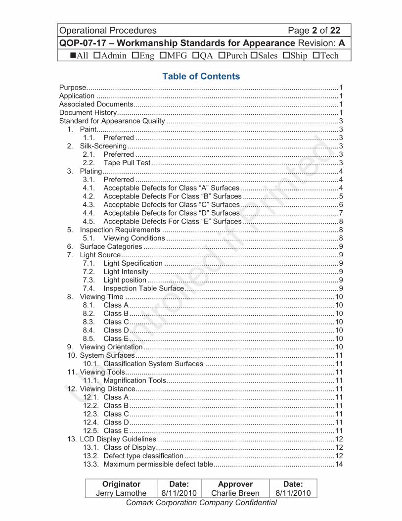
Table of Contents Purpose........................................................................................................................... 1
Application ...................................................................................................................... 1
Associated Documents.................................................................................................... 1
Document History ............................................................................................................ 1
Standard for Appearance Quality .................................................................................... 3
1. Paint...................................................................................................................... 3
1.1. Preferred ................................................................................................... 3
2. Silk-Screening ....................................................................................................... 3
2.1. Preferred ................................................................................................... 3
2.2. Tape Pull Test ........................................................................................... 3
3. Plating ................................................................................................................... 4
3.1. Preferred ................................................................................................... 4
4.1. Acceptable Defects for Class “A” Surfaces ................................................ 4
4.2. Acceptable Defects For Class “B” Surfaces ............................................... 5
4.3. Acceptable Defects for Class “C” Surfaces ................................................ 6
4.4. Acceptable Defects for Class “D” Surfaces ................................................ 7
4.5. Acceptable Defects For Class “E” Surfaces ............................................... 8
5. Inspection Requirements ...................................................................................... 8
5.1. Viewing Conditions .................................................................................... 8
6. Surface Categories ............................................................................................... 9
7. Light Source .......................................................................................................... 9
7.1. Light Specification ..................................................................................... 9
7.2. Light Intensity ............................................................................................ 9
7.3. Light position ............................................................................................. 9
7.4. Inspection Table Surface ........................................................................... 9
8. Viewing Time ...................................................................................................... 10
8.1. Class A .................................................................................................... 10
8.2. Class B .................................................................................................... 10
8.3. Class C .................................................................................................... 10
8.4. Class D .................................................................................................... 10
8.5. Class E .................................................................................................... 10
9. Viewing Orientation ............................................................................................. 10
10. System Surfaces ................................................................................................. 11
10.1. Classification System Surfaces ............................................................... 11
11. Viewing Tools ...................................................................................................... 11
11.1. Magnification Tools .................................................................................. 11
12. Viewing Distance................................................................................................. 11
12.1. Class A .................................................................................................... 11
12.2. Class B .................................................................................................... 11
12.3. Class C .................................................................................................... 11
12.4. Class D .................................................................................................... 11
12.5. Class E .................................................................................................... 11
13. LCD Display Guidelines ...................................................................................... 12
13.1. Class of Display ....................................................................................... 12
13.2. Defect type classification ......................................................................... 12
13.3. Maximum permissible defect table ........................................................... 14

Operational Procedures Page 3 of 22
QOP-07-17 – Workmanship Standards for Appearance Revision: A
nAll oAdmin oEng oMFG oQA oPurch oSales oShip oTech
Originator Jerry Lamothe
Date: 8/11/2010
Approver Charlie Breen
Date: 8/11/2010
Comark Corporation Company Confidential
13.4. Measure method/control conditions for pixel defects ............................... 14
14. LCD Window Cosmetic Specifications ................................................................ 15
14.1. Lighting environment ............................................................................... 15
14.2. Inspection Method ................................................................................... 15
14.3. Inspection Procedure ............................................................................... 15
14.4. Evaluation Method ................................................................................... 16
14.5. For Windows With Viewing Areas > 2 Square Feet. ................................ 16
14.6. For Windows With Viewing Areas < 2 Square Feet ................................. 17
15. Comark Corporation Internal Inferior Workmanship Escalation ........................... 17
15.1. If this Workmanship Standard does not identify a defect ......................... 17
15.2. Escalation Process .................................................................................. 17
16. Order of Precedence ........................................................................................... 18
17. Terms and Defect Definitions .............................................................................. 18
18. References ......................................................................................................... 22
18.1. Department of Defense ........................................................................... 22
18.2. IPC .......................................................................................................... 22
18.3. ISO13406-2 and ISO 9431-307, Class II ................................................. 22
18.4. View Thru Technologies Cosmetic Specification ..................................... 22
Standard for Appearance Quality
1. Paint
1.1. Preferred
Painted surfaces should be defect free and the texture and color should be uniform throughout the entire surface.
The finish on a continuous surface shall exhibit no gross imperfections such as gouges, large chips, runs, blisters, oil spots, flaking, or any defects that will affect the functional properties of the finish.
Paint touch-up is acceptable.
A touch-up is not acceptable if visible at the viewing distance for that class of surface.
2. Silk-Screening
2.1. Preferred
Silk-screened logos or symbols should be defect free, and should withstand cleaning with mild solvents and the tape pull test.
2.2. Tape Pull Test
The tape pull test is a non-destructive test of silk-screened parts. Use a 3M Scotch Brand #600 for all silkscreen pull tests.
This tape is common used by the industry due it is close to matching the specifications callout in ASTM D3359-76: “Measuring Adhesion by Tape Test”, 36+/- 2.5 oz/in

Operational Procedures Page 4 of 22
QOP-07-17 – Workmanship Standards for Appearance Revision: A
nAll oAdmin oEng oMFG oQA oPurch oSales oShip oTech
Originator Jerry Lamothe
Date: 8/11/2010
Approver Charlie Breen
Date: 8/11/2010
Comark Corporation Company Confidential
2.2.1. Tape pull test procedure
· Smooth tape into place by finger
· Within 90 sec +/-30 sec of applying the tape, remove by seizing the free end pulling it off rapidly back upon itself, as close to an angle of 180 degrees as possible.
· Inspect the tape and the tested area for removal of paint
3. Plating
3.1. Preferred
Visible outside surfaces should be defect free, and die and slug marks should not be visible.
The finish shall have uniform appearance;
Visual appearance will vary between different alloys and between machined, milled, cast, and grained surfaces.
Outside surface shall be free from scratches, dents, or gouges.
4. Acceptable Defects Matrix
4.1. Acceptable Defects for Class “A” Surfaces
Viewing time Viewing distance Ten (10) seconds per 200 square inches per part, Five (5) seconds per 50 square inches
for front panels 24 Inch (610 mm)
DEFECT ACCEPT REJECT
Bleed out Up to 5/16” away from seam.
Touch up allowed. Any greater than 5/16”
Blister None Any
Blush Accept per approved engineering
document.
Bubble None Any
Burns Accept per approved engineering
document.
Burrs Less than 10% of material
thickness Any greater than 10%
Cloudiness None Any
Contamination None Any
Corrosion / Rust / Oxidation None Any
Cracks None Any
Dent / Ding / Pitting None Any
Discoloration color consistency
Accept per approved engineering document for 100% uniformity of
surface. Partial discoloration
Dirt / Lint / Specks / Smudge
Less than or equal to 0.02” Any greater than 0.02”
Flash Accept per approved engineering
document.
Flow Marks None Any

Operational Procedures Page 5 of 22
QOP-07-17 – Workmanship Standards for Appearance Revision: A
nAll oAdmin oEng oMFG oQA oPurch oSales oShip oTech
Originator Jerry Lamothe
Date: 8/11/2010
Approver Charlie Breen
Date: 8/11/2010
Comark Corporation Company Confidential
DEFECT ACCEPT REJECT Fingerprints None Any
Flaking / Chipping / Peeling None Any
Metal Fuzz None Any
Paint Non-Adhesion / Non-Uniformity / Inconsistency
None Any
Paint runs None Any
Scratches / Gouges Qty. 3, less than or equal to 0.01”
x 0.03”
More than qty. 3. Any bare metal or base metal on a painted
surface
Scuff Marks Accept per approved engineering
document.
Short-Shots None Any
Sink Less than or equal to 0.003deep Any greater than 0.003”
Smearing None Any
Spot weld, Welding Lines Accept per approved engineering
document.
Texture / Gloss / Finish 100% uniformity of surface,
Accept per approved engineering document.
Partial variation
Tooling marks / Die marks / Slug mark / Punch mark /
Burnish marks
Accept per approved engineering document.
Voids Less than or equal to 0.01” Any greater than 0.01”
Water Spots None Any
4.2. Acceptable Defects For Class “B” Surfaces
Viewing time Viewing distance Seven (7) seconds per 200 square inches per
part 30 Inch (760 mm)
DEFECT ACCEPT REJECT
Bleed out Up to 3/8” away from seam.
Touch up allowed. Any greater than 3/8”
Blister None Any
Blush Accept per approved engineering
document.
Bubble None Any
Burns Accept per approved engineering document.
Burrs Less than 10% of material
thickness Any greater than 10%
Cloudiness None Any
Contamination Qty. 1, Less than or equal to
0.03” More than qty. 1 per surface or
any greater than 0.03”
Corrosion / Rust / Oxidation None Any
Cracks None Any
Dent / Ding / Pitting None Any
Discoloration color consistency Non-Uniformity
90% uniformity of surface. More than 10% surface
discoloration or consistency
Dirt / Lint / Specks / Smudge
Qty. 3, Less than or equal to 0.03”
More than qty. 3 per surface or any greater than 0.03”
Flash Less than or equal to 0.005” in
height Any greater than 0.005” in height
Flow Marks None Any
Operational Procedures Page 6 of 22
QOP-07-17 – Workmanship Standards for Appearance Revision: A
nAll oAdmin oEng oMFG oQA oPurch oSales oShip oTech
Originator Jerry Lamothe
Date: 8/11/2010
Approver Charlie Breen
Date: 8/11/2010
Comark Corporation Company Confidential
DEFECT ACCEPT REJECT Fingerprints Surface 99% fingerprint free More than 1% of the surface
Flaking / Chipping / Peeling Less than or equal to 0.03” Any bare metal greater than 0.03”
or any exposed base metal
Metal Fuzz None Any
Paint Non-Adhesion / None Any
Paint runs None Any
Scratches / Gouges Qty. 2; Less than or equal to
0.02” x 0.09”; Qty. 1; Less than or equal to 0.01” x 0.25”;
More than limit qty. per surface. Any exposed base metal on
painted surfaces
Scuff Marks Accept per approved engineering
document.
Short-Shots None Any
Sink Less than or equal to 0.005” deep Any greater than 0.005” deep
Smearing None Any
Spot weld, Welding Lines Less than or equal
to 0.005” in height or depth Any greater than 0.005” in height
or depth
Texture / Gloss / Finish Less than or equal to 0.02” x
0.25” Any greater than 0.02” x 0.25”
Tooling marks / Die marks / Slug mark / Punch mark /
Burnish marks
Accept per approved engineering document.
Voids Less than or equal to 0.03” Any greater than 0.03”
Water Spots None Any
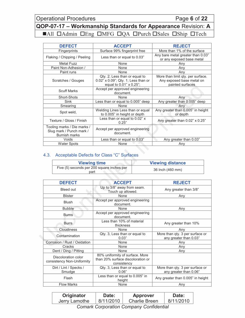
4.3. Acceptable Defects for Class “C” Surfaces
Viewing time Viewing distance Five (5) seconds per 200 square inches per
part 36 Inch (460 mm)
DEFECT ACCEPT REJECT
Bleed out Up to 3/8” away from seam.
Touch up allowed. Any greater than 3/8”
Blister None Any
Blush Accept per approved engineering
document.
Bubble None Any
Burns Accept per approved engineering
document.
Burrs Less than 10% of material
thickness Any greater than 10%
Cloudiness None Any
Contamination Qty. 3, Less than or equal to
0.03” More than qty. 3 per surface or
any greater than 0.03”
Corrosion / Rust / Oxidation None Any
Cracks None Any
Dent / Ding / Pitting None Any
Discoloration color consistency Non-Uniformity
80% uniformity of surface. More than 20% surface discoloration or
consistency
Dirt / Lint / Specks / Smudge
Qty. 3, Less than or equal to 0.06”
More than qty. 3 per surface or any greater than 0.06”
Flash Less than or equal to 0.005” in
height Any greater than 0.005” in height
Flow Marks None Any

Operational Procedures Page 7 of 22
QOP-07-17 – Workmanship Standards for Appearance Revision: A
nAll oAdmin oEng oMFG oQA oPurch oSales oShip oTech
Originator Jerry Lamothe
Date: 8/11/2010
Approver Charlie Breen
Date: 8/11/2010
Comark Corporation Company Confidential
DEFECT ACCEPT REJECT Fingerprints Surface 95% fingerprint free More than 5% of the surface
Flaking / Chipping / Peeling Less than or equal to 0.09” Any bare metal greater than0.09”
or any exposed base metal
Metal Fuzz None Any
Paint Non-Adhesion Non-Adhesion
None Any
Paint runs None Any
Scratches / Gouges
Qty. 4; Less than or equal to 0.02” x 0.25”; Qty. 1; Less than or equal to 0.01” x 0.5”; More than
limit qty. per surface.
Any exposed base metal on painted surfaces
Scuff Marks Accept per approved engineering
document.
Short-Shots None Any
Sink Qty. 1, Less than or equal to
0.015” deep Any greater than 0.015” deep
Smearing None Any
Spot weld, Welding Lines Less than or equal
to 0.005” in height or depth Any greater than 0.005” in height
or depth
Texture / Gloss / Finish Less than or equal to 0.02” x
0.09” Any greater than 0.02” x 0.09”
Tooling marks / Die marks /Slug mark / Punch mark /
Burnish marks
Accept per approved engineering document.
Voids Less than or equal to 0.03” Any greater than 0.03”
Water Spots None Any
4.4. Acceptable Defects for Class “D” Surfaces
Viewing time Viewing distance Five (3) seconds per 200 square inches per
part 36 Inch (460 mm)
DEFECT ACCEPT REJECT
Bleed out Up to 3/8” away from seam.
Touch up allowed. Any greater than 3/8”
Blister None Any
Blush Accept per approved engineering
document.
Bubble None Any
Burns Accept per approved engineering
document.
Burrs Less than 10% of material
thickness Any greater than 10%
Cloudiness None Any
Contamination Qty. 3, Less than or equal to
0.06” More than qty. 3 per surface or
any greater than 0.06”
Corrosion / Rust / Oxidation None Any
Cracks None Any
Dent / Ding / Pitting Less than or equal to 0.09” in
depth Any greater than 0.09”
Discoloration color consistency Non-Uniformity
70% uniformity of surface. More than 30% surface
discoloration or consistency
Dirt / Lint / Specks / Smudge
Qty. 5, Less than or equal to 0.09”
More than qty. 5 per surface or any greater than 0.09”

Operational Procedures Page 8 of 22
QOP-07-17 – Workmanship Standards for Appearance Revision: A
nAll oAdmin oEng oMFG oQA oPurch oSales oShip oTech
Originator Jerry Lamothe
Date: 8/11/2010
Approver Charlie Breen
Date: 8/11/2010
Comark Corporation Company Confidential
DEFECT ACCEPT REJECT
Flash Less than or equal to 0.02” in
height Any greater than 0.02” in height
Flow Marks None Any
Fingerprints Surface 90% fingerprint free More than 10% of the surface
Flaking / Chipping / Peeling Less than or equal to 0.09” Any bare metal greater than 0.09”
or any exposed base metal
Metal Fuzz None Any
Paint Non-Adhesion None Any
Paint runs Qty. 1, Less than or equal to
0.02” x 0.5” More Than qty.1 or any greater
than 0.02” x 0.5”
Scratches / Gouges Less than or equal to 0.02” x
0.25”; Qty. 3; Less than or equal to 0.01” x 0.5”;
More than limit qty. per surface. Any exposed base metal on
painted surfaces
Scuff Marks Accept per approved engineering
document.
Short-Shots None Any
Sink Qty. 1, Less than or equal to
0.03” deep Any greater than 0.03” deep
Smearing None Any
Spot weld, Welding Lines Less than or equal to 0.005” in
height or depth Any greater than 0.005” in height
or depth
Texture / Gloss / Finish Less than or equal to 0.25” x
0.25” Any greater than 0.25” x 0.25”
Tooling marks / Die marks / Slug mark / Punch mark /
Burnish marks Any
Any exposed base metal on painted surfaces
Voids Less than or equal to 0.06” Any greater than 0.06”
Water Spots None Any
4.5. Acceptable Defects For Class “E” Surfaces
Viewing time Viewing distance Unspecified Unspecified
DEFECT ACCEPT REJECT Fingerprints Surface 50% fingerprint free More than 50% of the surface
Metal Fuzz None Any
Blush Accept per approved engineering
document.
Cosmetic Flaws All kinds of touchup allowed
Any flaw that impacts the functionality of the part. Any
exposed base metal on painted surfaces. Defective corrosion
protection.
5. Inspection Requirements
5.1. Viewing Conditions
The inspector shall scan the surface in a continuous manner. All judgments shall be made from the specified lighting, viewing distance, angle and material classes as described below.
Operational Procedures Page 9 of 22
QOP-07-17 – Workmanship Standards for Appearance Revision: A
nAll oAdmin oEng oMFG oQA oPurch oSales oShip oTech
Originator Jerry Lamothe
Date: 8/11/2010
Approver Charlie Breen
Date: 8/11/2010
Comark Corporation Company Confidential
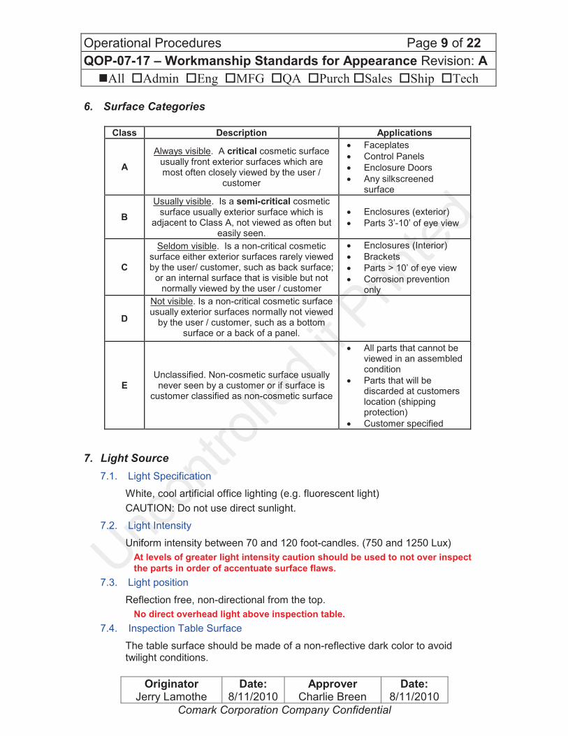
6. Surface Categories
Class Description Applications
A
Always visible. A critical cosmetic surface usually front exterior surfaces which are most often closely viewed by the user /
customer
· Faceplates
· Control Panels
· Enclosure Doors
· Any silkscreened surface
B
Usually visible. Is a semi-critical cosmetic surface usually exterior surface which is
adjacent to Class A, not viewed as often but easily seen.
· Enclosures (exterior)
· Parts 3’-10’ of eye view
C
Seldom visible. Is a non-critical cosmetic surface either exterior surfaces rarely viewed by the user/ customer, such as back surface;
or an internal surface that is visible but not normally viewed by the user / customer
· Enclosures (Interior)
· Brackets
· Parts > 10’ of eye view
· Corrosion prevention only
D
Not visible. Is a non-critical cosmetic surface usually exterior surfaces normally not viewed
by the user / customer, such as a bottom surface or a back of a panel.
E Unclassified. Non-cosmetic surface usually never seen by a customer or if surface is
customer classified as non-cosmetic surface
· All parts that cannot be viewed in an assembled condition
· Parts that will be discarded at customers location (shipping protection)
· Customer specified
7. Light Source
7.1. Light Specification
White, cool artificial office lighting (e.g. fluorescent light)
CAUTION: Do not use direct sunlight.
7.2. Light Intensity
Uniform intensity between 70 and 120 foot-candles. (750 and 1250 Lux)
At levels of greater light intensity caution should be used to not over inspect
the parts in order of accentuate surface flaws.
7.3. Light position
Reflection free, non-directional from the top.
No direct overhead light above inspection table.
7.4. Inspection Table Surface
The table surface should be made of a non-reflective dark color to avoid twilight conditions.
Operational Procedures Page 10 of 22
QOP-07-17 – Workmanship Standards for Appearance Revision: A
nAll oAdmin oEng oMFG oQA oPurch oSales oShip oTech
Originator Jerry Lamothe
Date: 8/11/2010
Approver Charlie Breen
Date: 8/11/2010
Comark Corporation Company Confidential
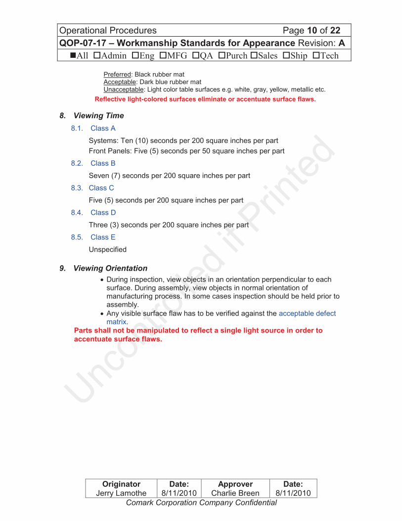
Preferred: Black rubber mat Acceptable: Dark blue rubber mat Unacceptable: Light color table surfaces e.g. white, gray, yellow, metallic etc.
Reflective light-colored surfaces eliminate or accentuate surface flaws.
8. Viewing Time
8.1. Class A
Systems: Ten (10) seconds per 200 square inches per part
Front Panels: Five (5) seconds per 50 square inches per part
8.2. Class B
Seven (7) seconds per 200 square inches per part
8.3. Class C
Five (5) seconds per 200 square inches per part
8.4. Class D
Three (3) seconds per 200 square inches per part
8.5. Class E
Unspecified
9. Viewing Orientation
· During inspection, view objects in an orientation perpendicular to each surface. During assembly, view objects in normal orientation of manufacturing process. In some cases inspection should be held prior to assembly.
· Any visible surface flaw has to be verified against the acceptable defect matrix.
Parts shall not be manipulated to reflect a single light source in order to
accentuate surface flaws.
Operational Procedures Page 11 of 22
QOP-07-17 – Workmanship Standards for Appearance Revision: A
nAll oAdmin oEng oMFG oQA oPurch oSales oShip oTech
Originator Jerry Lamothe
Date: 8/11/2010
Approver Charlie Breen
Date: 8/11/2010
Comark Corporation Company Confidential
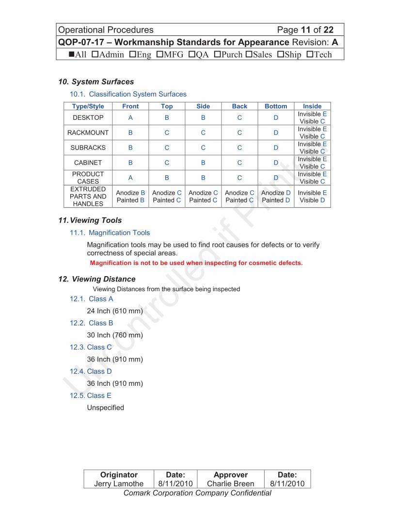
10. System Surfaces
10.1. Classification System Surfaces
Type/Style Front Top Side Back Bottom Inside
DESKTOP A B B C D Invisible E Visible C
RACKMOUNT B C C C D Invisible E Visible C
SUBRACKS B C C C D Invisible E Visible C
CABINET B C B C D Invisible E Visible C
PRODUCT CASES
A B B C D Invisible E Visible C
EXTRUDED PARTS AND HANDLES
Anodize B Painted B
Anodize C Painted C
Anodize C Painted C
Anodize C Painted C
Anodize D Painted D
Invisible E Visible D
11. Viewing Tools
11.1. Magnification Tools
Magnification tools may be used to find root causes for defects or to verify correctness of special areas.
Magnification is not to be used when inspecting for cosmetic defects.
12. Viewing Distance
Viewing Distances from the surface being inspected
12.1. Class A
24 Inch (610 mm)
12.2. Class B
30 Inch (760 mm)
12.3. Class C
36 Inch (910 mm)
12.4. Class D
36 Inch (910 mm)
12.5. Class E
Unspecified
Operational Procedures Page 12 of 22
QOP-07-17 – Workmanship Standards for Appearance Revision: A
nAll oAdmin oEng oMFG oQA oPurch oSales oShip oTech
Originator Jerry Lamothe
Date: 8/11/2010
Approver Charlie Breen
Date: 8/11/2010
Comark Corporation Company Confidential
13. LCD Display Guidelines
13.1. Class of Display
Class 0 Applied to uses like medical imaging-type products where high sensitivity and importance to minimize risk in the information perception is critical.
Class I Applied to specific video display tasks where high sensitivity and special importance to pixel faults is less risky. This is the Comark standard Class.
Class II General User display tasks like reading and process text information where reading performance is not inhibited by pixel defects.
Class III
For display tasks with less sensitivity to pixel faults like processing public information and advertisement, text book reading, or fast moving images where defective pixels do not cause discomfort to the User.
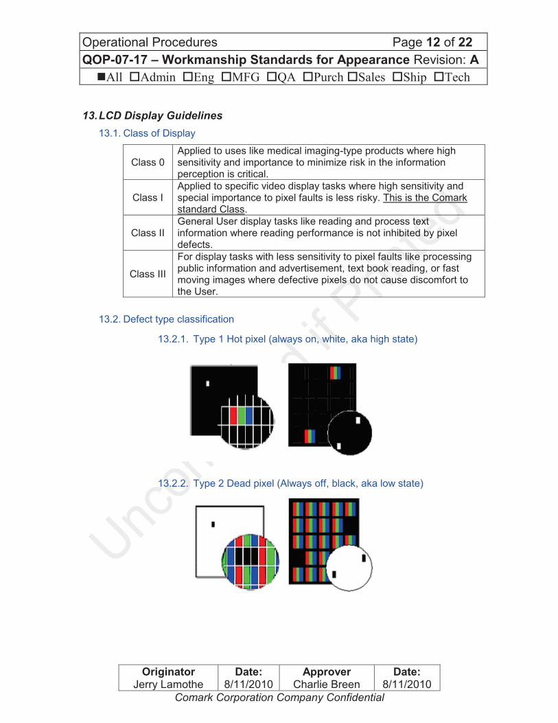
13.2. Defect type classification
13.2.1. Type 1 Hot pixel (always on, white, aka high state)
13.2.2. Type 2 Dead pixel (Always off, black, aka low state)

Operational Procedures Page 13 of 22
QOP-07-17 – Workmanship Standards for Appearance Revision: A
nAll oAdmin oEng oMFG oQA oPurch oSales oShip oTech
Originator Jerry Lamothe
Date: 8/11/2010
Approver Charlie Breen
Date: 8/11/2010
Comark Corporation Company Confidential
13.2.3. Type 3 Stuck pixel (either red, blue, or green, always on or off)
13.2.4. Type 4 Faulty clusters (5x5 pixels)
13.2.5. Other defects.
A different type of defect caused by microscopic contaminants within the manufacturing process can also be found. Contamination results in a dark "stain" covering one or several sub-pixels. They are not pixel or sub-pixel defects per say. No contamination is allowed under Comark policy.

Operational Procedures Page 14 of 22
QOP-07-17 – Workmanship Standards for Appearance Revision: A
nAll oAdmin oEng oMFG oQA oPurch oSales oShip oTech
Originator Jerry Lamothe
Date: 8/11/2010
Approver Charlie Breen
Date: 8/11/2010
Comark Corporation Company Confidential
13.3. Maximum permissible defect table
The following table defines the maximum permissible number of pixel faults for the respective resolution types validly for the pixel error Class I.
Maximum permissible number of errors for the pixel error Class I
in accordance with ISO 13406-2 and ISO 9241-307
Physical
Resolution
Number
of pixels
Type 1
Stuck High
Type 2
Stuck Low
Type 3
Stuck pixel
Cluster
fault
Type 1 &
Type 2
Cluster
fault
Type 3
XGA
1024 x 768 768,432 1 2 1 0 0
WXGA
1280 x 800 1,024,000 1 2 1 0 0
SXGA
1280 x 1024 1,310,720 2 3 2 0 0
UXGA
1600 x 1200 1,920,000 2 4 2 0 0
WUXGA
1920 x 1080 2,073,600 2 4 2 0 0
13.4. Measure method/control conditions for pixel defects
In observance of the ISO 13406-2 and ISO 9431-307 standards, the following conditions are considered:
· Final control for pixel fault done right after Burn-in, i.e. pre-heating of display.
· Ambient temperature ~ 77°
· Relative air humidity 40-70 %
· Viewing distance 24 inches.
· Ambient illumination of 300 to 500 lux
· Viewing angle of 70 to 110 degrees horizontal and 80 to 110 degrees vertical.
· Viewing duration ~30 seconds.

Operational Procedures Page 15 of 22
QOP-07-17 – Workmanship Standards for Appearance Revision: A
nAll oAdmin oEng oMFG oQA oPurch oSales oShip oTech
Originator Jerry Lamothe
Date: 8/11/2010
Approver Charlie Breen
Date: 8/11/2010
Comark Corporation Company Confidential
14. LCD Window Cosmetic Specifications
This document describes the inspection environment, procedures and acceptance
criteria for LCD windows.
14.1. Lighting environment
Two 4' GE F40-C50 fluorescent bulbs (or equivalent) shall be mounted above the inspection table and perpendicular to the inspector’s line of sight. Hanging at the rear surface of the inspection table, directly in front of the inspector, will be a black area and a white area. These are used as backgrounds during inspection. During inspections, the window may never be back-lit or edge-lit directly by the fluorescent bulbs. A light box shall be used for part of the inspection. The light box is composed of 4 F40-C50 fluorescent bulbs mounted behind a sheet of white acrylic (R&H 7447 or equivalent). Measurements are to be made with a contact reticle with 6-15X magnification (ref: Edmund Scientific 6X Pocket Comparator w/ Reticle #30-585, p/n 41-055
14.2. Inspection Method
Inspect the window through the viewing surface only. Disregard any blemishes within 0.060” of any machined edge.
14.2.1. For windows with a viewing area of < 2 ft2, the following inspections shall be conducted from a distance of 18 inches.
14.2.2. For windows with a viewing area of greater than 2 ft2, but less than 4 ft2, the following inspections shall be conducted from a distance of 48 inches.
14.2.3. For windows with a viewing area of greater than 4 ft2, the following inspections shall be conducted from a distance of 72 inches.
14.3. Inspection Procedure
Operational Procedures Page 16 of 22
QOP-07-17 – Workmanship Standards for Appearance Revision: A
nAll oAdmin oEng oMFG oQA oPurch oSales oShip oTech
Originator Jerry Lamothe
Date: 8/11/2010
Approver Charlie Breen
Date: 8/11/2010
Comark Corporation Company Confidential
14.3.1. Front Surface Inspection: Hold the window below and behind the light source and in front of the black background. Tilt the window to scan the reflection of the light bulb across the front surface. Look for defects while tilting the window.
14.3.2. Sub-Surface Inspection #1: Hold the window in the same location as in step A, but keep the window perpendicular to your line of sight. Look for defects while holding the window in that position.
14.3.3. Sub-Surface Inspection #2: Repeat step 14.3.2 in front of the white background.
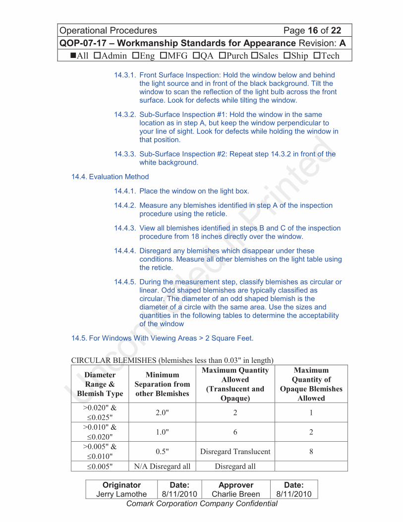
14.4. Evaluation Method
14.4.1. Place the window on the light box.
14.4.2. Measure any blemishes identified in step A of the inspection procedure using the reticle.
14.4.3. View all blemishes identified in steps B and C of the inspection procedure from 18 inches directly over the window.
14.4.4. Disregard any blemishes which disappear under these conditions. Measure all other blemishes on the light table using the reticle.
14.4.5. During the measurement step, classify blemishes as circular or linear. Odd shaped blemishes are typically classified as circular. The diameter of an odd shaped blemish is the diameter of a circle with the same area. Use the sizes and quantities in the following tables to determine the acceptability of the window
14.5. For Windows With Viewing Areas > 2 Square Feet.
CIRCULAR BLEMISHES (blemishes less than 0.03" in length)
Diameter
Range &
Blemish Type
Minimum
Separation from
other Blemishes
Maximum Quantity
Allowed
(Translucent and
Opaque)
Maximum
Quantity of
Opaque Blemishes
Allowed
>0.020" &
£0.025" 2.0" 2 1
>0.010" &
£0.020" 1.0" 6 2
>0.005" &
£0.010" 0.5" Disregard Translucent 8
£0.005" N/A Disregard all Disregard all

Operational Procedures Page 17 of 22
QOP-07-17 – Workmanship Standards for Appearance Revision: A
nAll oAdmin oEng oMFG oQA oPurch oSales oShip oTech
Originator Jerry Lamothe
Date: 8/11/2010
Approver Charlie Breen
Date: 8/11/2010
Comark Corporation Company Confidential
LINEAR BLEMISHES (blemishes greater than 0.03" in length)
Maximum Thickness Maximum Allowed
>0.002" & £0.003" 0.2" cumulative length
£0.002" Disregard All
14.6. For Windows With Viewing Areas < 2 Square Feet
CIRCULAR DEFECTS (blemishes less than 0.05" in length)
Diameter
Range &
Blemish Type
Minimum
Separation from
other Blemishes
Maximum Quantity
Allowed per Window
(Translucent and
Opaque)
Maximum
Quantity of
Opaque Blemishes
Allowed per
Window
>0.030" &
≤0.040" 4.0”
0.5 per sq ft of
viewing area
0.25 per sq ft of
viewing area
>0.020" &
≤0.030" 2.0"
1 per sq ft of viewing
area
0.5 per sq ft of
viewing area
>0.015" &
≤0.020" 0.5”
3 per sq ft of viewing
area
1 per sq ft of
viewing area
>0.010" &
≤0.015" 0.1” Disregard Translucent
5 per sq ft of
viewing area
≤0.010" N/A Disregard all Disregard all
LINEAR BLEMISHES (blemishes greater than 0.05" in length)
Maximum Thickness Maximum Allowed
>0.002" & ≤0.003" 0.2" cumulative length per square foot of
viewing area
≤0.002" Disregard All
15. Comark Corporation Internal Inferior Workmanship Escalation
15.1. If this Workmanship Standard does not identify a defect
Every team member has to question inferior workmanship ONLY when you see a defect that is not clearly identified within this workmanship standard.
15.2. Escalation Process
When questioning a system or part for inferior workmanship issues follow this escalation process:
15.2.1. Locate the suspected defect
15.2.2. Check the Workmanship Standard, and any applicable engineering specifications

Operational Procedures Page 18 of 22
QOP-07-17 – Workmanship Standards for Appearance Revision: A
nAll oAdmin oEng oMFG oQA oPurch oSales oShip oTech
Originator Jerry Lamothe
Date: 8/11/2010
Approver Charlie Breen
Date: 8/11/2010
Comark Corporation Company Confidential
15.2.3. If no specification or special instructions are applicable, contact following support team members
· QC Team member
· Responsible Engineer
· Quality Manager
15.2.4. The Support team member must evaluate and make a decision on the suspected defect.
16. Order of Precedence
In case of a conflict between this Workmanship standard, Work Instructions, engineering specification or other applicable specifications, following hierarchy will apply:
· Approved Deviation
· Engineering Specification
· Work Instruction
· Workmanship Standard
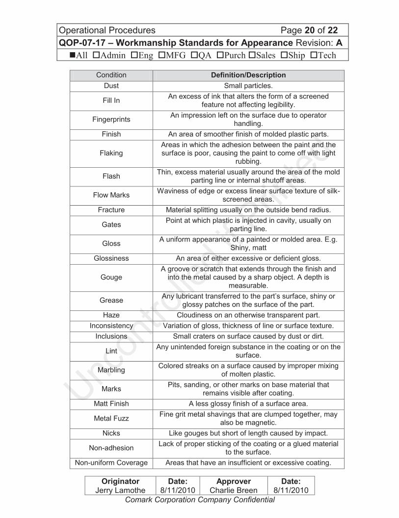
17. Terms and Defect Definitions
Condition Definition/Description
Accept per approved engineering drawing
Some cosmetic imperfections are not avoidable in certain process and design circumstances. Approved engineering documents will point this out.
Abrasion Surface imperfection that doesn’t remove or displace material appears as a scuff or changes to the surface
finish.
Bare Metal A metal surface that has an intact protective coating but
no cosmetic finish.
Base Metal A bare metal surface on which the protective coating has
been compromised.
Bleed Out A Substance that runs out of seams. Color can vary from
brown, dark brown to gray white at plating.
Bleeding Rough and not densely packed dull gray lines at plated
material.
Blister A bubbling in the surface of the finish. Non-adhesion or
lack of proper sticking of the coating to the surface caused by trapped air, gas or moisture.
Blush Discoloration or change in gloss.
Burns Brown marks or streaks on a surface of the part caused
by trapped gases burning the surface of the plastic during molding operation.
Bubble A bubbling in the surface of the finish. Non-adhesion or
lack of proper sticking of the coating to the surface caused by trapped air, gas or moisture.

Operational Procedures Page 19 of 22
QOP-07-17 – Workmanship Standards for Appearance Revision: A
nAll oAdmin oEng oMFG oQA oPurch oSales oShip oTech
Originator Jerry Lamothe
Date: 8/11/2010
Approver Charlie Breen
Date: 8/11/2010
Comark Corporation Company Confidential
Condition Definition/Description
Bump Protrusions caused by trapped air / gas or moisture
usually seen in finished parts.
Burnish Marks Marks or lines that cannot be felt usually caused by tooling dies most common on flattened cold rolled
material e.g. Steel or aluminum sheets.
Burrs
Sharp edges around part features caused by manufacturing process like punching, shearing, milling or
drilling.
Sheet metal edges that are compliant to UL 1439 can still cut through protective gloves and/or human hands.
Chipping Areas in which the adhesion between the paint and the surface is poor, causing the paint to come off with light
rubbing.
Cloudiness A haziness or lack of clarity in otherwise transparent part.
Cluster (LCD Displays) 5x5 pixels
Contamination Rough and not densely packed dull gray lines at plated
material. Colored specks of foreign material embedded in or on the surface part.
Corrosion
Areas of corrosion on any metal surfaces.
Small areas of rust are acceptable where plating is removed by a standard manufacturing or welding
process, e.g. sheared (cut) edges.
Cracking
Crackled appearance due to poor adhesion usually from surface contamination before plating. Hairline cracks of anodized material caused by bending, high temperature curing after silk screening of the aluminum or tool mark hair cracks on the opposite site of the aluminum. Some
cracks can’t be avoided. Fine damages which may extend in a pattern on or beneath the surface or through a layer
of material.
Crazing A fine mesh of minute cracks on the surface of some
plastics due mainly to the effects of UV light.
Delaminating Separation, peeling of thin layer of material
Dent A surface depression caused by an impact.
Tooling marks are not dents.
Die marks Marks made on the metal’s surface when it is formed,
usually consist of long straight lines.
Ding Roughly funnel shaped dent caused by an impact.
Dirt Any particle of foreign material.
Discoloration Any change from the original color or shade in the finish.
Distortion A deformation of a die-casted part
Operational Procedures Page 20 of 22
QOP-07-17 – Workmanship Standards for Appearance Revision: A
nAll oAdmin oEng oMFG oQA oPurch oSales oShip oTech
Originator Jerry Lamothe
Date: 8/11/2010
Approver Charlie Breen
Date: 8/11/2010
Comark Corporation Company Confidential
Condition Definition/Description
Dust Small particles.
Fill In An excess of ink that alters the form of a screened
feature not affecting legibility.
Fingerprints An impression left on the surface due to operator
handling.
Finish An area of smoother finish of molded plastic parts.
Flaking Areas in which the adhesion between the paint and the surface is poor, causing the paint to come off with light
rubbing.
Flash Thin, excess material usually around the area of the mold
parting line or internal shutoff areas.
Flow Marks Waviness of edge or excess linear surface texture of silk-
screened areas.
Fracture Material splitting usually on the outside bend radius.
Gates Point at which plastic is injected in cavity, usually on
parting line.
Gloss A uniform appearance of a painted or molded area. E.g.
Shiny, matt
Glossiness An area of either excessive or deficient gloss.
Gouge A groove or scratch that extends through the finish and
into the metal caused by a sharp object. A depth is measurable.
Grease Any lubricant transferred to the part’s surface, shiny or
glossy patches on the surface of the part.
Haze Cloudiness on an otherwise transparent part.
Inconsistency Variation of gloss, thickness of line or surface texture.
Inclusions Small craters on surface caused by dust or dirt.
Lint Any unintended foreign substance in the coating or on the
surface.
Marbling Colored streaks on a surface caused by improper mixing
of molten plastic.
Marks Pits, sanding, or other marks on base material that
remains visible after coating.
Matt Finish A less glossy finish of a surface area.
Metal Fuzz Fine grit metal shavings that are clumped together, may
also be magnetic.
Nicks Like gouges but short of length caused by impact.
Non-adhesion Lack of proper sticking of the coating or a glued material
to the surface.
Non-uniform Coverage Areas that have an insufficient or excessive coating.
Operational Procedures Page 21 of 22
QOP-07-17 – Workmanship Standards for Appearance Revision: A
nAll oAdmin oEng oMFG oQA oPurch oSales oShip oTech
Originator Jerry Lamothe
Date: 8/11/2010
Approver Charlie Breen
Date: 8/11/2010
Comark Corporation Company Confidential
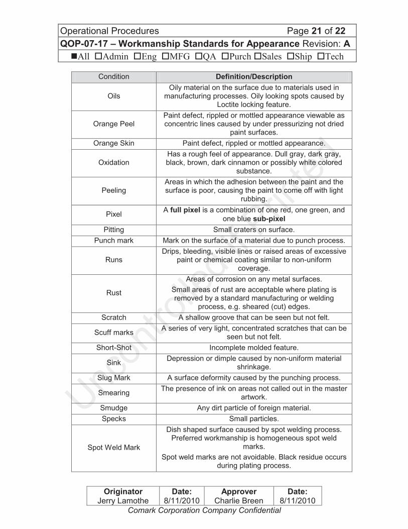
Condition Definition/Description
Oils Oily material on the surface due to materials used in
manufacturing processes. Oily looking spots caused by Loctite locking feature.
Orange Peel Paint defect, rippled or mottled appearance viewable as concentric lines caused by under pressurizing not dried
paint surfaces.
Orange Skin Paint defect, rippled or mottled appearance.
Oxidation Has a rough feel of appearance. Dull gray, dark gray, black, brown, dark cinnamon or possibly white colored
substance.
Peeling Areas in which the adhesion between the paint and the surface is poor, causing the paint to come off with light
rubbing.
Pixel A full pixel is a combination of one red, one green, and
one blue sub-pixel
Pitting Small craters on surface.
Punch mark Mark on the surface of a material due to punch process.
Runs Drips, bleeding, visible lines or raised areas of excessive
paint or chemical coating similar to non-uniform coverage.
Rust
Areas of corrosion on any metal surfaces.
Small areas of rust are acceptable where plating is removed by a standard manufacturing or welding
process, e.g. sheared (cut) edges.
Scratch A shallow groove that can be seen but not felt.
Scuff marks A series of very light, concentrated scratches that can be
seen but not felt.
Short-Shot Incomplete molded feature.
Sink Depression or dimple caused by non-uniform material
shrinkage.
Slug Mark A surface deformity caused by the punching process.
Smearing The presence of ink on areas not called out in the master
artwork.
Smudge Any dirt particle of foreign material.
Specks Small particles.
Spot Weld Mark
Dish shaped surface caused by spot welding process. Preferred workmanship is homogeneous spot weld
marks.
Spot weld marks are not avoidable. Black residue occurs during plating process.
Operational Procedures Page 22 of 22
QOP-07-17 – Workmanship Standards for Appearance Revision: A
nAll oAdmin oEng oMFG oQA oPurch oSales oShip oTech
Originator Jerry Lamothe
Date: 8/11/2010
Approver Charlie Breen
Date: 8/11/2010
Comark Corporation Company Confidential
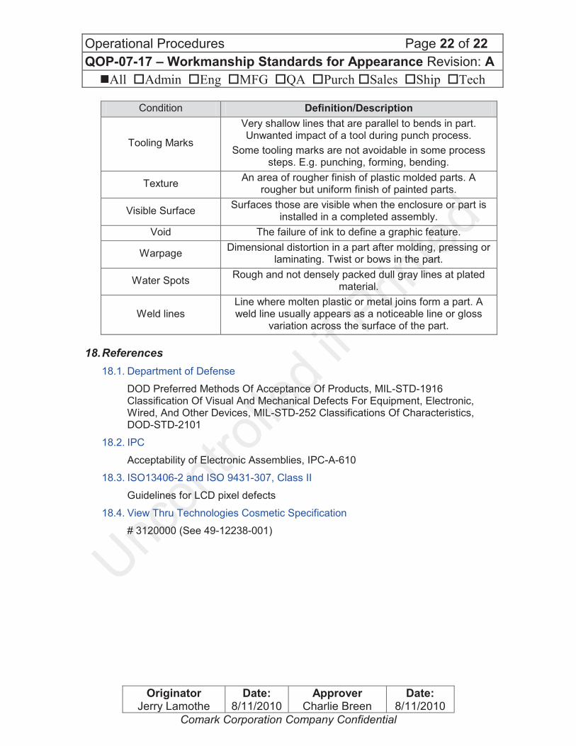
Condition Definition/Description
Tooling Marks
Very shallow lines that are parallel to bends in part. Unwanted impact of a tool during punch process.
Some tooling marks are not avoidable in some process steps. E.g. punching, forming, bending.
Texture An area of rougher finish of plastic molded parts. A
rougher but uniform finish of painted parts.
Visible Surface Surfaces those are visible when the enclosure or part is
installed in a completed assembly.
Void The failure of ink to define a graphic feature.
Warpage Dimensional distortion in a part after molding, pressing or
laminating. Twist or bows in the part.
Water Spots Rough and not densely packed dull gray lines at plated
material.
Weld lines Line where molten plastic or metal joins form a part. A weld line usually appears as a noticeable line or gloss
variation across the surface of the part.
18. References
18.1. Department of Defense
DOD Preferred Methods Of Acceptance Of Products, MIL-STD-1916 Classification Of Visual And Mechanical Defects For Equipment, Electronic, Wired, And Other Devices, MIL-STD-252 Classifications Of Characteristics, DOD-STD-2101
18.2. IPC
Acceptability of Electronic Assemblies, IPC-A-610
18.3. ISO13406-2 and ISO 9431-307, Class II
Guidelines for LCD pixel defects
18.4. View Thru Technologies Cosmetic Specification
# 3120000 (See 49-12238-001)