qucm eim valve controller - niobrara · qucm eim valve controller application manual 2 installation...
TRANSCRIPT

QUCM EIM Valve Controller Application Manual
QUCM EIM Valve ControllerInstallation and Programming Manual
This Manual describes the QUCM application for interfacing EIM Valve Actuators to a Modicon Quantum PLCsystem.
Effective: 29 May, 2005
Niobrara Research & Development CorporationP.O. Box 3418 Joplin, MO 64803 USA
Telephone: (800) 235-6723 or (417) 624-8918Facsimile: (417) 624-8920www.niobrara.com

Modicon and Quantum are trademarks of Schneider Electric.
Subject to change without notice.
© Niobrara Research & Development Corporation 2005. All Rights Reserved.
3
Contents
1 Introduction .........................................................................................................................5
2 Installation .............................................................................................................................7
QUCM Installation .........................................................................................................7Serial Connections to the QUCM-OE ............................................................................7
Port 1 to DDC2I to Valves ......................................................................................7Port 2 to DDC2I to Valves ......................................................................................7DDC2I DIP Switch Settings ....................................................................................8Valve Configuration and Wiring .............................................................................8Port 1 to the Personal Computer .............................................................................9
Loading the Applications into the QUCM .....................................................................9FWLOAD QUCM Firmware Update. ...................................................................10QLOAD Application 1 ..........................................................................................10
PLC Configuration .......................................................................................................11PLC Local Rack Setup ..........................................................................................11PLC Remote Rack Setup .......................................................................................13
3 Examples...............................................................................................................................17
Example 1 - I/O Scanner ..............................................................................................17Example 2 - Remote Rack ............................................................................................20
Figures
Figure 2-1 DDC2I to "A" port RS-485 2-wire cable .....................................................................7
Figure 2-2 DDC2I to "B" port RS-485 2-wire cable .....................................................................8
Figure 2-3 Typical E>Net Ring system setup ................................................................................8
Figure 2-4 PC Connection to QUCM-O serial port ........................................................................9
Figure 2-5 QUCM-O to RS-232 PC Port (9-pin) (MM1 Cable) ..................................................9
Figure 2-6 FWLOAD of QUCM Firmware .................................................................................10
Figure 2-7 QLOAD of Application 1 ...........................................................................................11
Figure 3-1 Example 1 with QUCM in PLC Processor Rack .......................................................17
Figure 3-2 Example 1 with QUCM in Remote Rack ...................................................................20

4
Tables
Table 2-1 DDC2I DIP Switch Settings ..........................................................................................8
Table 2-2 I/O Scanner Example ...................................................................................................13
Table 2-3 I/O Register Map ..........................................................................................................14
Table 2-4 Valve register 7 bitmap ................................................................................................15
Table 3-1 I/O Scanner Example ...................................................................................................18
Table 3-2 Possible Valve Status and PLC Values ........................................................................18
Table 3-3 Health Registers with all devices online ......................................................................19
Table 3-4 Health Registers with Cable break between slaves 13 and 14 .....................................19
Table 3-5 Example 2 I/O Register Map with all slaves online Port 1 ..........................................21

QUCM EIM Valve Controller Application Manual 1 Introduction 5
1
Introduction
The Niobrara QUCM is a TSX Quantum® compatible module that is capable of run-ning multiple applications for performing communication translations between serialprotocols. This document covers an application provides a Modbus RTU serial ringnetwork for controlling EIM valve actuators. Both serial ports of the QUCM-O areconnected to a closed ring of actuators and the QUCM can determine if the ring iscomplete and which valves are accessible from either port of the QUCM. This net-work topology allows for the breaking of the network in one location and still provid-ing control of all of the actuators.
The QUCM-O may be used in the local Quantum PLC processor rack an support up to128 actuators. The module is configured as an NOE-771-01 in the PLC and the I/OScanner table is used to define the actuators to be polled. The QUCM-O may also beused in a remote rack as an I/O module for communicating with up to 14 actuators. Inthis case the QUCM is configured by Holding registers assigned to the QUCM’s slot.
The application, "qucm_redundant_app1.qcm" is compiled and loaded into Applica-tion 1 of the QUCM-O. The application includes multiple threads for simultaneouslyservicing both serial ports.
Both serial ports of the QUCM are be used to connect to the actuator network. TheNiobrara DDC2I isolated RS-232<>RS-485 converter is recommended to connect theQUCM to the 2-wire RS-485 network. This converter provides optical isolation be-tween the Quantum PLC and the actuator network. A Niobrara MM1 cable is neededto load the application into the QUCM.


QUCM EIM Valve Controller Application Manual 2 Installation 7
2
Installation
QUCM InstallationMount the QUCM in an available slot in the register rack. Secure the screw at thebottom of the module.
Serial Connections to the QUCM-OE
Port 1 to DDC2I to Valves
The serial port of the QUCM-O must be switched to RS-232. The Niobrara cableMM0 is used to connect to the DDC2I. This cable is included with the DDC2I
Standard 2-wire twisted pair cable should be used from the Green Connector on theDDC2I to the first Valve "A" port. This cable pinout is shown in Figure 2-1.
Figure 2-1 DDC2I to "A" port RS-485 2-wire cable
Port 2 to DDC2I to Valves
The serial port of the QUCM-O must be switched to RS-232. The Niobrara cableMM0 is used to connect to the DDC2I. This cable is included with the DDC2I
Standard 2-wire twisted pair cable should be used from the Green Connector on theDDC2I to the first Valve "A" port. This cable pinout is shown in Figure 2-2.
DDC2I Green Connector A Screw
TX+ 25 (+)
TX- 24 (-)
RX+
RX-
Shield 23

8 Installation 2 QUCM EIM Valve Controller Application Manual
Figure 2-2 DDC2I to "B" port RS-485 2-wire cable
DDC2I DIP Switch Settings
The DDC2I DIP switches must be configured for 2-wire Slave with Termination butno Bias. Only switch 6 will be OFF. The valve will provide the bias for the 2-wiresegment. The settings are the same for both DDC2Is.
Table 2-1 DDC2I DIP Switch Settings
Valve Configuration and Wiring
The valves should be configured for "E>Net Ring". Refer to the appropriate EIMdocument for proper DIP switch configuration and wiring diagrams.
Figure 2-3 Typical E>Net Ring system setup
DDC2I Green Connector B Screw
TX+ 18 (+)
TX- 19 (-)
RX+
RX-
Shield 22
Switch Description Position
1 4/2 wire ON
2 4/2 wire ON
3 4/2 wire ON
4 Master/Slave ON
5 Termination ON
6 Bias OFF
MM0 Cable
140QUCMNiobrara
ActiveReadyRun
ColLnkTXERXE
12345
RN1TX1RX1
6789
10RN2TX2RX2
Fault DDC2I Valve 1A B
Valve 2A B
Valve 3A B
Valve 6B A
Valve 5B A
Valve 4B ADDC2I

QUCM EIM Valve Controller Application Manual 2 Installation 9
Port 1 to the Personal Computer
A physical connection must be made from the personal computer to the QUCM in or-der load the QUCM application program.. This link may be a serial connection from aCOM port on the personal computer to the RS-232 port on the QUCM-O. TheNiobrara MM1 cable may be used for this connection. This cable pinout is shown inFigure 2-5.
Figure 2-4 PC Connection to QUCM-O serial port
Figure 2-5 QUCM-O to RS-232 PC Port (9-pin) (MM1 Cable)
Loading the Applications into the QUCMThe QUCM-O must use the qucmtcpl.fwl firmware included in theQUCM_SETUP.EXE file. This firmware is dated 13May2005 or later.
MM1 Cable
PC
140QUCMNiobrara
ActiveReadyRun
ColLnkTXERXE
12345
RN1TX1RX1
6789
10RN2TX2RX2
Fault
RJ45 DE9S (female)
3 2
4 3
5 5
6 4
7 6
7
8

10 Installation 2 QUCM EIM Valve Controller Application Manual
FWLOAD QUCM Firmware Update.
Firmware upload is as follows:
1 Remove the module form the rack.
2 Move the RUN/LOAD switch on the back of the module to LOAD.
3 Replace the module in the rack and apply power.
4 Only the 3 light should be on. (The Link and RX E-net lights may be on if theE-net port is connected and there is traffic.)
5 Connect the PC to QUCM Port 1 with a MM1 cable.. Make sure that Port 1 is setto RS232 mode with the slide switch below the port.
6 From the Windows’ Start button select:"Start, Programs, Niobrara, QUCM, FWLOAD QUCM Firmware"
Verify that the file to load is qucmtcpl.fwl.Also verify that the proper PC serial port is selected.
7 Press the "Start Download" button. The download will only take a few minutesand it will notify the user when finished.
8 Remove the module from the rack and change the switch back to RUN.
Figure 2-6 FWLOAD of QUCM Firmware
QLOAD Application 1
1 Application 1 and 2 Switches must be in HALT.
2 Press "Start, Programs, Niobrara, QUCM, Apps, EIM, QLOAD EIM Application1"
3 Verify that the file to load is qucm_eim_app1.qcc

QUCM EIM Valve Controller Application Manual 2 Installation 11
4 Select the Modbus Serial Tab
5 Verify the proper PC’s com port is selected.
6 Verify the the baud rate is 9600, 8 bits, Even parity and ASCII is NOT checked..
7 Select the Application 1 Radio Button.
8 Press the Start Download button. QLOAD will open a progress window to showthe status of the download.
After downloading the application, move switch 1 to RUN and the RN1 should comeon. If the QUCM is to be used in the local PLC rack with the I/O Scanner setup thenmake sure that the switch 2 is set for either RUN or HALT. If the QUCM is to beused in a remote or local rack as I/O then set switch 2 to MEM PROT.
Figure 2-7 QLOAD of Application 1
PLC Configuration
PLC Local Rack Setup
The QUCM must be added in the I/O Map as an NOE-771-01. The QUCM then mayhave its Ethernet I/O Scanner configured.
Specify IP Address - Check this box.
IP Address - Set the IP Address of the QUCM.
Subnet Mask - Set the Subnet Mask of the QUCM.
Gateway - Set the default gateway for the QUCM.
Framing - Normally this would be set for ETHERNET II.

12 Installation 2 QUCM EIM Valve Controller Application Manual
Health Block - This is the starting 3x register or 1x coil of the 128 bits of statusfor QUCM port 1. Port 2’s 128 bits start immediately after Port 1.
In the example below the health block for Port 1 is in 300123-300130 andPort 2 is 300131-300138.
Diagnostic Block - This setting is ignored by the QUCM. Leave blank.
Slave IP Address - This setting is ignored by the QUCM. Leave 0.0.0.0.
Unit ID - This is the Modbus slave address of an actuator. The valid range is1-254.
The QUCM reserves the special ID=0 for serial port configuration parameters.
Health Timeout - Ignored for normal entries.
This is the baud rate for ID=0. Valid baud rates are 1200, 2400, 4800, 9600,19200, 38400. The default is 19200.
Rep Rate - Ignored in normal entries.
This is the serial port parity for ID=0. Valid settings are 0=NONE, 1=EVEN,2=ODD. The default is NONE.
Read Ref Master - This is the PLC register for the read data from the valves. Itmay be a 0x, 1x, 3x, or 4x address. The data from valve register 400007 (seeTable 2-4 for bit description) will be placed in this register while the value fromvalve register 400015 will be placed in this register plus 1.
This is the timeout value for ID=0. Enter the value in mS as a 4x register. Forexample, 400500 would provide a timeout of 500mS.
Read Ref Slave - This is the register in the valve actuator for the start of the read. This value must be 400007.
This it the retry count for ID=0. Enter the count as a 4x register. For example,40004 would provide 4 retires before the valve is marked offline.
Read Length - This is the number of words read from the valve. This valuemust be 2. The QUCM looks at the Read Ref Slave and if it is 400007 and theRead Length is 2 then the QUCM actually reads a block of registers from 7 to 15but only reports the data from 7 and 15 to the PLC.
This ignored for ID=0 but must be set to 1 for Concept.
Last Value (Input) - This can be set to zero the input if the device is offline or tohold the last data.
Ignored on ID=0.
QUCM EIM Valve Controller Application Manual 2 Installation 13
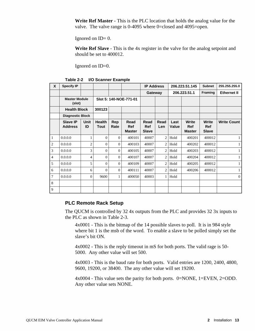
Write Ref Master - This is the PLC location that holds the analog value for thevalve. The valve range is 0-4095 where 0=closed and 4095=open.
Ignored on ID= 0.
Write Ref Slave - This is the 4x register in the valve for the analog setpoint andshould be set to 400012.
Ignored on ID=0.
Table 2-2 I/O Scanner Example
PLC Remote Rack Setup
The QUCM is controlled by 32 4x outputs from the PLC and provides 32 3x inputs tothe PLC as shown in Table 2-3.
4x0001 - This is the bitmap of the 14 possible slaves to poll. It is in 984 stylewhere bit 1 is the msb of the word. To enable a slave to be polled simply set theslave’s bit ON.
4x0002 - This is the reply timeout in mS for both ports. The valid rage is 50-5000. Any other value will set 500.
4x0003 - This is the baud rate for both ports. Valid entries are 1200, 2400, 4800,9600, 19200, or 38400. The any other value will set 19200.
4x0004 - This value sets the parity for both ports. 0=NONE, 1=EVEN, 2=ODD. Any other value sets NONE.
X Specify IP IP Address 206.223.51.145 Subnet 255.255.255.0
Gateway 206.223.51.1 Framing Ethernet II
Master Module(slot)
Slot 5: 140-NOE-771-01
Health Block 300123
Diagnostic Block
Slave IPAddress
UnitID
HealthTout
RepRate
ReadRef
Master
ReadRef
Slave
ReadLen
LastValue
WriteRef
Master
WriteRef
Slave
Write Count
1 0.0.0.0 1 0 0 400101 40007 2 Hold 400201 400012 1
2 0.0.0.0 2 0 0 400103 40007 2 Hold 400202 400012 1
3 0.0.0.0 3 0 0 400105 40007 2 Hold 400203 400012 1
4 0.0.0.0 4 0 0 400107 40007 2 Hold 400204 400012 1
5 0.0.0.0 5 0 0 400109 40007 2 Hold 400205 400012 1
6 0.0.0.0 6 0 0 400111 40007 2 Hold 400206 400012 1
7 0.0.0.0 0 9600 1 400050 40003 1 Hold 0
8
9

14 Installation 2 QUCM EIM Valve Controller Application Manual
4x0005 through 4x0018 - These are the setpoint values for the 14 possible valves. The PLC should load a value 0 to close the valve or up to 4095 to fully open thevalve.
4x0019 through 4x0032 - These are the slave addresses for the 14 possible valvesto poll. The valid range is 1-255.
Table 2-3 I/O Register Map
PLCOutput
Description PLCInput
Description
4x0001 Bitmap of slaves to poll (984 style) 1-14 3x0001 QUCM Runtime Status (normally x8000 hex)
4x0002 Reply timeout (in mS) 3x0002 QUCM Halt Register or slave being polled
4x0003 Baud Rate (1200, 2400, 4800, 9600,19200, 38400)
3x0003 Port 1 status of slaves (984 style) bits 1-14
4x0004 Parity 0=NONE, 1=EVEN, 2=ODD 3x0004 Port 2 status of slaves (984 style) bits 1-14
4x0005 Slave 1 Register 12 (0-4095) 3x0005 Slave 1 Register 400007
4x0006 Slave 2 Register 12 (0-4095) 3x0006 Slave 1 Register 400015
4x0007 Slave 3 Register 12 (0-4095) 3x0007 Slave 2 Register 400007
4x0008 Slave 4 Register 12 (0-4095) 3x0008 Slave 2 Register 400015
4x0009 Slave 5 Register 12 (0-4095) 3x0009 Slave 3 Register 400007
4x0010 Slave 6 Register 12 (0-4095) 3x0010 Slave 3 Register 400015
4x0011 Slave 7 Register 12 (0-4095) 3x0011 Slave 4 Register 400007
4x0012 Slave 8 Register 12 (0-4095) 3x0012 Slave 4 Register 400015
4x0013 Slave 9 Register 12 (0-4095) 3x0013 Slave 5 Register 400007
4x0014 Slave 10 Register 12 (0-4095) 3x0014 Slave 5 Register 400015
4x0015 Slave 11 Register 12 (0-4095) 3x0015 Slave 6 Register 400007
4x0016 Slave 12 Register 12 (0-4095) 3x0016 Slave 6 Register 400015
4x0017 Slave 13 Register 12 (0-4095) 3x0017 Slave 7 Register 400007
4x0018 Slave 14 Register 12 (0-4095) 3x0018 Slave 7 Register 400015
4x0019 Slave 1 Modbus Address (1-255) 3x0019 Slave 8 Register 400007
4x0020 Slave 2 Modbus Address (1-255) 3x0020 Slave 8 Register 400015
4x0021 Slave 3 Modbus Address (1-255) 3x0021 Slave 9 Register 400007
4x0022 Slave 4 Modbus Address (1-255) 3x0022 Slave 9 Register 400015
4x0023 Slave 5 Modbus Address (1-255) 3x0023 Slave 10 Register 400007
4x0024 Slave 6 Modbus Address (1-255) 3x0024 Slave 10 Register 400015
4x0025 Slave 7 Modbus Address (1-255) 3x0025 Slave 11 Register 400007
4x0026 Slave 8 Modbus Address (1-255) 3x0026 Slave 11 Register 400015
4x0027 Slave 9 Modbus Address (1-255) 3x0027 Slave 12 Register 400007
4x0028 Slave 10 Modbus Address (1-255) 3x0028 Slave 12 Register 400015
4x0029 Slave 11 Modbus Address (1-255) 3x0029 Slave 13 Register 400007
4x0030 Slave 12 Modbus Address (1-255) 3x0030 Slave 13 Register 400015
4x0031 Slave 13 Modbus Address (1-255) 3x0031 Slave 14 Register 400007
4x0032 Slave 14 Modbus Address (1-255) 3x0032 Slave 14 Register 400015

QUCM EIM Valve Controller Application Manual 2 Installation 15
3x0001 - This is the runtime status of the QUCM application. If the applicationis running then only bit 1 (msb) will be set. If the application halts then the rea-son for the halt will be displayed in this register. Consult the QUCM user man-ual for the meaning of the halt code.
3x0002 - This register normally shows the slave being polled and it will cyclequickly between 1 and 14. If 3x0001 shows a halt code then this register willshow the QUCM source code line number for the halt.
3x0003 - This register shows the bitmap of active devices polled by QUCM port1 in 984 style (bit 1 is msb). If Port 1 receives responses from a slave then thatslave’s bit will be ON.
3x0004 - This register shows the bitmap of active devices polled by QUCM port2 in 984 style (bit 1 is msb). Normally this register is zero because Port 1 is poll-ing all of the slaves. If Port 2 no longer sees the queries from Port 1 then it willattempt to communicate with the slaves that Port 1 can’t see. When Port 2 re-ceives replies from slaves then it will turn on the appropriate bits in 3x0004. Bycomparing 3x0003 and 3x0004 the user can see where a break in the loop occurs.
3x0005, 7, 9, 11, 13, 15, 17, 19, 23, 25, 27, 29, and 31 - These registers providethe value from the valve’s register 4x0007. This is the bitmap of Inputs 16-31 asshown in Table 2-4 (in 984 style).
3x0006, 8, 10, 12, 14, 16, 18, 20, 22, 24, 26, 28, 30, and 32 - These registers pro-vide the value from the valve’s register 4x0015. This is the analog position ofthe valve in 12-bit. 0=closed. 4095=open.
Table 2-4 Valve register 7 bitmap
Valve 4x0007 Bit Description
1 (msb) Unit alarm (all alarms OR’ed)
2 reserved for host (always 0)
3 Actuator fail alarm
4 Local ESD alarm
5 Phase monitor alarm
6 Motor overload alarm (Motor thermal)
7 Power monitor alarm
8 Valve stall alarm (valve not moving)
9 Close torque alarm (TSC)
10 Open torque alarm (TSO)
11 Selector Switch Remote/Auto
12 Selector Switch Local/Manual
13 Closing Status (valve moving close)
14 Opening Status (valve moving open)
15 Close Limit Switch (LSC)
16 (lsb) Open Limit Switch (LSO)


QUCM EIM Valve Controller Application Manual 3 Examples 17
3
Examples
Example 1 - I/O ScannerFigure 3-1 shows a QUCM in the Processor Rack slot 5 with a ring of 6 valves. Eachvalve is set for slave address 11 through 16 and is configured for 19200 baud, NONEparity.
Figure 3-1 Example 1 with QUCM in PLC Processor Rack
Table shows the I/O Scanner configuration for this system. Entries 1 through 6 arethe polls for the valves. Entry 7 sets the communication parameters for the QUCM. Table 3-2 gives some possible valve positions and the PLC register values that corre-spond to these conditions.
MM0 Cable
140QUCMNiobrara
ActiveReadyRun
ColLnkTXERXE
12345
RN1TX1RX1
6789
10RN2TX2RX2
Fault DDC2I Valve 1A B
Valve 2A B
Valve 3A B
Valve 6B A
Valve 5B A
Valve 4B ADDC2I
PLC Rack Slot 5
Slave11
Slave12
Slave13
Slave14
Slave15
Slave16

18 Examples 3 QUCM EIM Valve Controller Application Manual
Table 3-1 I/O Scanner Example
Table 3-2 Possible Valve Status and PLC Values
Table 3-3 shows the Health Status registers in the PLC when all 6 slaves are onlinewith QUCM port 1. Table 3-4 shows the Health Status when the cable between slaves13 and 14 is cut leaving slaves 11, 12, and 13 on QUCM port 1 and slaves 14, 15, and16 on QUCM Port 2.
X Specify IP IP Address 206.223.51.145 Subnet 255.255.255.0
Gateway 206.223.51.1 Framing Ethernet II
Master Module(slot)
Slot 5: 140-NOE-771-01
Health Block 300123
Diagnostic Block
Slave IPAddress
UnitID
HealthTout
RepRate
ReadRef
Master
ReadRef
Slave
ReadLen
LastValue
WriteRef
Master
WriteRef
Slave
Write Count
1 0.0.0.0 11 0 0 400101 40007 2 Hold 400201 400012 1
2 0.0.0.0 12 0 0 400103 40007 2 Hold 400202 400012 1
3 0.0.0.0 13 0 0 400105 40007 2 Hold 400203 400012 1
4 0.0.0.0 14 0 0 400107 40007 2 Hold 400204 400012 1
5 0.0.0.0 15 0 0 400109 40007 2 Hold 400205 400012 1
6 0.0.0.0 16 0 0 400111 40007 2 Hold 400206 400012 1
7 0.0.0.0 0 19200 0 400250 40003 1 Hold 0
8
9
Valve Status PLC OutputRegister (dec)
PLC InputRegister (dec)
PLC InputRegister (hex)
1 (slave 11) Closed, No alarms 400201 = 0 400101 = 2400102 = 0
400101 = 0002400102 = 0000
2 (slave 12) Open, No alarms 400202 = 4095 400103 = 1400104 = 4095
400103 = 0001400104 = 0FFF
3 (slave 13) Closing, No alarms 400203 = 0 400105 = 8400106 = 2012
400105 = 0008400106 = 0840
4 (slave 14) Opening, No alarms 400204 = 4095 400107 = 16400108 = 1021
400107 = 0010400108 = 03FD
5 (slave 15) 1/2 Opened, Noalarms
400205 = 2048 400109 = 0400110 = 2048
400109 = 0000400110 = 0800
6 (slave 16) Partially Opened,Stalled.
400206 = 4095 400111 = 33024400112 = 4000
400111 = 8100400112 = 0FA0

QUCM EIM Valve Controller Application Manual 3 Examples 19
Table 3-3 Health Registers with all devices online
Table 3-4 Health Registers with Cable break between slaves 13 and 14
PLC Register Description Value (hex) Value (bin)
300123 Port 1 - Slaves 1-16 FC00 1111 1100 0000 0000
300124 Port 1 - Slaves 17-32 0000 0000 0000 0000 0000
300125 Port 1 - Slaves 33-48 0000 0000 0000 0000 0000
300126 Port 1 - Slaves 49-64 0000 0000 0000 0000 0000
300127 Port 1 - Slaves 65-80 0000 0000 0000 0000 0000
300128 Port 1 - Slaves 81-96 0000 0000 0000 0000 0000
300129 Port 1 - Slaves 97-112 0000 0000 0000 0000 0000
300130 Port 1 - Slaves 113-128 0000 0000 0000 0000 0000
300131 Port 2 - Slaves 1-16 0000 0000 0000 0000 0000
300132 Port 2 - Slaves 17-32 0000 0000 0000 0000 0000
300133 Port 2 - Slaves 33-48 0000 0000 0000 0000 0000
300134 Port 2 - Slaves 49-64 0000 0000 0000 0000 0000
300135 Port 2 - Slaves 65-80 0000 0000 0000 0000 0000
300136 Port 2 - Slaves 81-96 0000 0000 0000 0000 0000
300137 Port 2 - Slaves 97-112 0000 0000 0000 0000 0000
300138 Port 2 - Slaves 113-128 0000 0000 0000 0000 0000
PLC Register Description Value (hex) Value (bin)
300123 Port 1 - Slaves 1-16 E000 1110 0000 0000 0000
300124 Port 1 - Slaves 17-32 0000 0000 0000 0000 0000
300125 Port 1 - Slaves 33-48 0000 0000 0000 0000 0000
300126 Port 1 - Slaves 49-64 0000 0000 0000 0000 0000
300127 Port 1 - Slaves 65-80 0000 0000 0000 0000 0000
300128 Port 1 - Slaves 81-96 0000 0000 0000 0000 0000
300129 Port 1 - Slaves 97-112 0000 0000 0000 0000 0000
300130 Port 1 - Slaves 113-128 0000 0000 0000 0000 0000
300131 Port 2 - Slaves 1-16 1C00 0001 1100 0000 0000
300132 Port 2 - Slaves 17-32 0000 0000 0000 0000 0000
300133 Port 2 - Slaves 33-48 0000 0000 0000 0000 0000
300134 Port 2 - Slaves 49-64 0000 0000 0000 0000 0000
300135 Port 2 - Slaves 65-80 0000 0000 0000 0000 0000
300136 Port 2 - Slaves 81-96 0000 0000 0000 0000 0000
300137 Port 2 - Slaves 97-112 0000 0000 0000 0000 0000
300138 Port 2 - Slaves 113-128 0000 0000 0000 0000 0000

20 Examples 3 QUCM EIM Valve Controller Application Manual
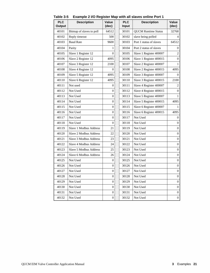
Example 2 - Remote RackFigure 3-2 shows another setup with the QUCM-O in a remote PLC rack with PLCregisters 300101-300132 and 400101-400132 assigned to it. Six valves are attachedwith Modbus Slave addresses 21 through 26 at 9600 baud, EVEN parity.
Figure 3-2 Example 1 with QUCM in Remote Rack
Table 3-5 shows the PLC register data for an online system with some valves openand closed.
MM0 Cable
140QUCMNiobrara
ActiveReadyRun
ColLnkTXERXE
12345
RN1TX1RX1
6789
10RN2TX2RX2
Fault DDC2I Valve 1A B
Valve 2A B
Valve 3A B
Valve 6B A
Valve 5B A
Valve 4B ADDC2I
Slave21
Slave22
Slave23
Slave26
Slave25
Slave24
Remote Rack 300101 - 300132 400101 - 400132
QUCM EIM Valve Controller Application Manual 3 Examples 21
Table 3-5 Example 2 I/O Register Map with all slaves online Port 1
PLCOutput
Description Value(dec)
PLCInput
Description Value(dec)
40101 Bitmap of slaves to poll 64512 30101 QUCM Runtime Status 32768
40102 Reply timeout 500 30102 slave being polled 4
40103 Baud Rate 9600 30103 Port 1 status of slaves 64512
40104 Parity 1 30104 Port 2 status of slaves 0
40105 Slave 1 Register 12 0 30105 Slave 1 Register 400007 2
40106 Slave 2 Register 12 4095 30106 Slave 1 Register 400015 0
40107 Slave 3 Register 12 2100 30107 Slave 2 Register 400007 1
40108 Slave 4 Register 12 0 30108 Slave 2 Register 400015 4095
40109 Slave 5 Register 12 4095 30109 Slave 3 Register 400007 0
40110 Slave 6 Register 12 4095 30110 Slave 3 Register 400015 2100
40111 Not used 0 30111 Slave 4 Register 400007 2
40112 Not Used 0 30112 Slave 4 Register 400015 0
40113 Not Used 0 30113 Slave 5 Register 400007 1
40114 Not Used 0 30114 Slave 5 Register 400015 4095
40115 Not Used 0 30115 Slave 6 Register 400007 1
40116 Not Used 0 30116 Slave 6 Register 400015 4095
40117 Not Used 0 30117 Not Used 0
40118 Not Used 0 30118 Not Used 0
40119 Slave 1 Modbus Address 21 30119 Not Used 0
40120 Slave 2 Modbus Address 22 30120 Not Used 0
40121 Slave 3 Modbus Address 23 30121 Not Used 0
40122 Slave 4 Modbus Address 24 30122 Not Used 0
40123 Slave 5 Modbus Address 25 30123 Not Used 0
40124 Slave 6 Modbus Address 26 30124 Not Used 0
40125 Not Used 0 30125 Not Used 0
40126 Not Used 0 30126 Not Used 0
40127 Not Used 0 30127 Not Used 0
40128 Not Used 0 30128 Not Used 0
40129 Not Used 0 30129 Not Used 0
40130 Not Used 0 30130 Not Used 0
40131 Not Used 0 30131 Not Used 0
40132 Not Used 0 30132 Not Used 0