r11881925 orano - wa
TRANSCRIPT

Q orano
Orano Federal Services LLC
2101 Hom Rapids Rd
Richland, WA 99354
Tel: +1 509 371 1893
www.orano.group
March 21 , 2018
Ms. Andrea Dorsey Subcontractor Administrator Bechtel National , Inc. 2435 Stevens Center Place Richland , WA 99354
Dear Ms. Dorsey:
Ill I llllll 111111111111111111 R11881925
BECHTEL NATIONAL, INC. CONTRACT NO. 24590-CM-HC4-HXYG-00240 IQRPE STRUCTURAL INTEGRITY ASSESSMENT REPORT FOR DFLAW EMF DEP CRITICAL PIPING ANCILLARY EQUIPMENT (IA-3021153-000)
The integrity assessment of the subject Critical Piping Ancillary Equipment has been completed per the contract requirements and is enclosed for your use. The assessment found that the design is sufficient to ensure that the Critical Piping Ancillary Equipment is adequately designed and has sufficient structural strength , compatibility with the waste(s) to be processed/ stored /treated , and corrosion protection to ensure that it will not collapse, rupture, or fail.
If you have any questions, please contact Tarlok Hundal at (509) 371-1975, or via email at [email protected].
Sincerely,
Tess Klatt Contract Administrator Orano Federal Services LLC Richland Office
Lap cc: J.S. Evans, w/Enclosure (1)
0 orano
www.orano.group
IA-3021153-000
IQRPE STRUCTURAL INTEGRITY ASSESSMENT REPORT FOR
DFLAW EMF DEP CRITICAL PIPING ANCILLARY EQUIPMENT
Please note that source, special nuclear and byproduct materials, as defined in the Atomic Energy Act of 1954 (AEA), are regulated at the U.S. Department of Energy (DOE) facilities exclusively by DOE acting pursuant to its AEA authority. DOE asserts that pursuant to the AEA, it has sole and exclusive responsibility and authority to regulate source, special nuclear, and byproduct materials at DOE-owned nuclear facilities. Information contained herein on radionuclides is provided for process description purposes only.
0 orano
www.orano.group
IA-3021153-000
IQRPE STRUCTURAL INTEGRITY ASSESSMENT REPORT FOR
DFLAW EMF DEP CRITICAL PIPING ANCILLARY EQUIPMENT
"I, Tarlok Singh Hundal, have reviewed and certified a portion of the design of a new tank system component located at the Hanford Waste Treatment Plant, owned/operated by Department of Energy, Office of River Protection , Richland , Washington . My duties were independent review of the current design for the DFLAW EMF DEP Critical Piping Ancillary Equipment, as required by the Washington Administrative Code, Dangerous Waste Regulations, Section WAC-173-303-640(3) (a) through (g) applicable components."
"I certify under penalty of law that I have personally examined and am familiar with the information submitted in this document and all attachments and that, based on my inquiry of those individuals immediately responsible for obtaining the information , I believe that the information is true, accurate, and complete. I am aware that there are significant penalties for submitting false information , including the possibility of fine and imprisonment."
The documentation reviewed indicates that the design fully satisfies the requirements of the WAC.
The attached review is seventeen (17) pages numbered one (1) through seventeen (17).

IQRPE Structural Integrity Assessment Report for DFLA W EMF DEP Critical Piping Ancillary Equipment
IA-3021153-000
~ Scope of 8 this Integrity
00 Assessment
Summary of Assessment
3/21/18
This integrity assessment addresses the critical piping ancillary equipment associated with the DFLA W Effluent Management Facility (EMF) DVP system. The critical piping ancillary equipment included pipelines, valves, and other items associated with numerous vessels, miscellaneous units or plant items, are conspicuously delineated on the P&ID drawings listed in the References section below. The critical piping ancillary equipment herein will be mainly termed as ancillary equipment, throughout the report.
For each item of "Information Assessed" (i.e. , Criteria) on the following pages, the documents listed under "Source of Information" were reviewed and found to furnish adequate design requirements and controls to ensure that the design fully satisfies the requirements of Washington Administrative Code (WAC), Chapter 173-303 WAC, Dangerous Waste Regulations, W AC-173-303-640, Tank Systems.
Note: Numerous change documents were issued against various documents listed in the "References" section and "Source of Information" column below. The change documents were reviewed and those which had any impact on the "Assessment" results were appropriately included, however, those which did not have any impact on the "Assessment" results were not included herein .
Page I of 17 Orano Federal Services LLC

IQRPE Structural Integrity Assessment Report for DFLA W EMF DEP Critical Piping Ancillary Equipment
IA-3021153-000
'',: '
' ,'
Plant Drawings:
24590-BOF-Pl-25-00001, Rev. I, Balance of Facilities LAW Effluent Process Bldg & LAW Effluent Drain Tank Bldg General Arrangement Plan at El. 0 ' - 0"; 24590-BOF-Pl-25-00002, Rev. I, Balance of Facilities LAW Effluent Process Bldg & LAW Effluent Drain Tank Bldg General Arrangement Sections A, B & C;
"' 24590-BOF-MS-V l 7T-000 12, Rev. 0, Process Flow Diagram Direct Feed Effluent Evaporator (System DEP);
~ 24590-BOF-MS-V l 7T-000 13, Rev. 0, Process Flow Diagram Direct Feed Concentrate Transfer (System DEP and DVP); CJ = 24590-BOF-M6-DEP-00002001, Rev. I, P&ID-BOF/EMF Direct Feed LAW EMF Process System Evaporator Feed Vessel t Drawings ~ DEP-VSL-00002; ~ 24590-BOF-M6-DEP-00003001, Rev. 1, P&ID-BOF/EMF Direct Feed LAW EMF Process System Evaporator Separator ~
DEP-EVAP-00001 ; 24590-BOF-M6-DEP-00003002, Rev. 1, P&ID-BOF/EMF Direct Feed LAW EMF Process System Evaporator Reboiler DEP-RBLR-00001 ; 24590-BOF-M6-DEP-00003004, Rev. 1, P&ID-BOF/EMF Direct Feed LAW EMF Process System Evaporator Condensers D EP-CON D-00001/2/3; 24590-BOF-M6-DEP-00003006, Rev. 1, P&ID-BOF/EMF Direct Feed LAW EMF Process System Reboiler Condensate DEP-VSL-00008.
3/21/18 Page 2 of 17 Orano Federal Services LLC

IQRPE Structural Integrity Assessment Report for DFLA W EMF DEP Critical Piping Ancillary Equipment
IA-3021153-000
Plant Drawings (cont' d):
24590-BOF-P3-DEP-GV00005001 , Rev. 0, Balance of Facilities Isometric (Line No. DEP-GV-00005-S l lX-1 ); 24590-BOF-P3-DEP-PW00006001 , Rev . 0, Balance of Facilities Isometric (Line No. DEP-PW-00006-S 11 X-18); 24590-BOF-P3-DEP-PW00006002, Rev . 0, Balance of Facilities Isometric (Line No. DEP-PW-00006-S 11 X-18); 24590-BOF-P3-DEP-PW000l 7001 , Rev. 0, Balance of Facilities Isometric (Line No. DEP-PW-00017-Sl 1 X-2); 24590-BOF-P3-DEP-PW000 17002, Rev. 0, Balance of Facilities Isometric (Line No. DEP-PW-00017-S 11 X-2); 24590-BOF-P3-DEP-PW000l 7003, Rev. 0, Balance of Facilities Isometric (Line No. DEP-PW-00017-S 11 X-1.5); 24590-BOF-P3-DEP-PW000 1800 I, Rev. 0, Balance of Facilities Isometric (Line No. DEP-PW-00018-S 11 X-2); 24590-BOF-P3-DEP-PW000 1900 I , Rev. 0, Balance of Facilities Isometric (Line No. DEP-PW-00019-S 11 X-2);
- 24590-BOF-P3-DEP-PW00020001 , Rev. 0, Balance of Facilities Isometric (Line No. DEP-PW-00020-S 11 X-2); "'0 24590-BOF-P3-DEP-PW00020002, Rev. 0, Balance of Facilities Isometric (Line No. DEP-PW-00020-S 11 X-4); ... = 24590-BOF-P3-DEP-PW0002 I 00 I, Rev. 0, Balance of Facilities Isometric (Line No. DEP-PW-00021-S 11 X-4); 0 CJ 24590-BOF-P3-DEP-PW0002 I 002, Rev. 0, Balance of Facilities Isometric (Line No. DEP-PW-00021-S 11 X-4); -~ Drawings 24590-BOF-P3-DEP-PW00023001 , Rev. 0, Balance of Facilities Isometric (Line No. DEP-PW-00023-S 11 X-3); ~ CJ
= 24590-BOF-P3-DEP-PW00023002, Rev. 0, Balance of Facilities Isometric (Line No. DEP-PW-00023-S 11 X-3); ~ :r. 24590-BOF-P3-DEP-PW00023003, Rev. 0, Balance of Facilities Isometric (Line No. DEP-PW-00023-S 11 X-1.5); ~
~ 24590-BOF-P3-DEP-PW0002400 I, Rev. 0, Balance of Facilities Isometric (Line No. DEP-PW-00024-S I I X-3); ~ 24590-BOF-P3-DEP-PW0002500I , Rev. 0, Balance of Facilities Isometric (Line No. DEP-PW-00025-S 11 X-4); 24590-BOF-P3-DEP-PW0003900I , Rev. 0, Balance of Facilities Isometric (Line No. DEP-PW-00039-S 11 X-2); 24590-BOF-P3-DEP-ZR0005000 I, Rev. 0, Balance of Facilities Isometric (Line No. DEP-ZR-00050-N 11 F-2); 24590-BOF-P3-DEP-ZR0005 I 00 I, Rev. 0, Balance of Facilities Isometric (Line No. DEP-ZR-00051-N 11 F-2); 24590-BOF-P3-DEP-ZS0003500 I, Rev. 0, Balance of Facilities Isometric (Line No. DEP-ZS-00035-N 11 F-16); 24590-BOF-P3-DEP-ZS00035002, Rev. 0, Balance of Facilities Isometric (Line No. DEP-ZS-00035-Nl lF-16); 24590-BOF-P3-DEP-ZS00036001 , Rev. 0, Balance of Facilities Isometric (Line No. DEP-ZS-00036-Nl IF-12); 24590-BOF-P3-DEP-ZS00054001, Rev. 0, Balance of Facilities Isometric (Line No. DEP-ZS-00054-N 11 F-12); 24590-BOF-P3-DEP-ZS000 17001 , Rev. I, Balance of Facilities Isometric (Line No. DEP-ZS-00017-S 11 C-02); 24590-BOF-P3-DEP-ZS000 17002, Rev. 0, Balance of Facilities Isometric (Line No.DEP-ZS-00017-S 11 C-02); 24590-BOF-P3-DEP-ZS000 17003, Rev. 0, Balance of Facilities Isometric (Line No. DEP-ZS-00017-S 11 C-02).
3/21/18 Page 3 of 17 Orano Federal Services LLC

IQRPE Structural Integrity Assessment Report for DFLA W EMF DEP Critical Piping Ancillary Equipment
... ,.
Plant Drawings (Cont' d)
Engineered Pipe Support Drawings: 24590-BOF-DEP-H00187, Rev. 0, Pipe Support Drawing; 24590-BOF-DEP-H00 I 88, Rev. 0, Pipe Support Drawing; 24590-BOF-DEP-H00l98, Rev. 0, Pipe Support Drawing; 24590-BOF-DEP-H00I 99, Rev. 0, Pipe Support Drawing; 24590-BOF-DEP-H0I 047, Rev. 0, Pipe Support Drawing; 24590-BOF-DEP-H0I 146, Rev. 0, Pipe Support Drawing; 24590-BOF-DEP-H0l 147, Rev. 0, Pipe Support Drawing; 24590-BOF-DEP-H0l438, Rev. 0, Pipe Support Drawing; 24590-BOF-DEP-H0J439, Rev. 0, Pipe Support Drawing; -- 24590-BOF-DEP-H01466, Rev. 0, Pipe Support Drawing; "0 ... 24590-BOF-DEP-H0l640, Rev. 0, Pipe Support Drawing; = 0 24590-BOF-DEP-H0J660, Rev. 0, Pipe Support Drawing; ~ - 24590-BOF-DEP-H0 I 661 , Rev. 0, Pipe Support Drawing; "' Drawings Q,I
~ 24590-BOF-DEP-H01682, Rev. 0, Pipe Support Drawing; = Q,I 24590-BOF-DEP-H0J686, Rev. 0, Pipe Support Drawing. I,.,
~ Q,I
~ Standard Pipe Support Drawings: 24590-WTP-PH-50-0000100 I, Rev. 4, Standard Pipe Support Details, Axial Stop-Welded (AW); 24590-WTP-PH-50-0000300 I, Rev. 4, Standard Pipe Support Details, Cantilever-Cantilever (CC); 24590-WTP-PH-50-00012001 , Rev . 7, Standard Pipe Support Details, Guide-U Bolts (GU); 24590-WTP-PH-50-00012002, Rev. 6, Standard Pipe Support Details, Guide-U Strap (GU); 24590-WTP-PH-50-00012003, Rev. 4, Standard Pipe Support Details, Guide-U Strap (GU); 24590-WTP-PH-50-0001400 I, Rev. I, Standard Pipe Support Details, Rods-Hangers (RH); 24590-WTP-PH-50-00014002, Rev. I , Standard Pipe Support Details, Rods-Hangers (RH); 24590-WTP-PH-50-00014003, Rev. I, Standard Pipe Support Details, Rods-Hangers (RH); 24590-WTP-PH-50-00016001 , Rev. 4, Standard Pipe Support Details, Shoes-Clamped (SC); 24590-WTP-PH-50-00019001, Rev. 4, Standard Pipe Support Details, Shoes-Welded (SW); 24590-WTP-PH-50-00004001, Rev. 4, Standard Pipe Support Details, Frames- L Shape (FL).
IA-3021153-000
3/21 / 18 Page 4 of 17 Orano Federal Services LLC

IQRPE Structural Integrity Assessment Report for DFLA W EMF DEP Critical Piping Ancillary Equipment
- MS Line Lists: "O ~ -= 0 24590-BOF-M6WX-DEP-00002001 , Rev. I, MS Line List for 24590-BOF-M6-DEP-0000200 I; c.i .._,
MS Line 24590-BOF-M6WX-DEP-00003001 , Rev. I, MS Line List for 24590-BOF-M6-DEP-00003001 ; ,.,, Q,j
Lists 24590-BOF-M6WX-DEP-00003002, Rev. I , MS Line List for 24590-BOF-M6-DEP-00003002; c.i = Q,j 24590-BOF-M6WX-DEP-00003003, Rev. I , MS Line List for 24590-BOF-M6-DEP-00003003; i.
~ 24590-BOF-M6WX-DEP-00003004, Rev. I , MS Line List for 24590-BOF-M6-DEP-00003004; Q,j
~ 24590-BOF-M6WX-DEP-00003006, Rev. I , MS Line List for 24590-BOF-M6-DEP-00003006.
3/21/18 Page 5 of 17
IA-3021153-000
Orano Federal Services LLC

IQRPE Structural Integrity Assessment Report for DFLA W EMF DEP Critical Piping Ancillary Equipment
.
Information Assessed Source of Information
Drawings listed above under References; Ancillary equipment
= design standards are 24590-WTP-DC-PS-01-001 , Rev. 9, Pipe Stress Design Criteria Including "Pipe Stress Criteria" and "Span Method Criteria;" ~ appropriate and "<ii
adequate for the ASME B31.3 Code, Process Piping, American Society of ~
~ equipment's intended Mechanical Engineers; use. 24590-WTP-RPT-ST-01-001 , Rev. 2, RPP-WTP Compliance
With Uniform Building Code Seismic Design Requirements.
3/21/18 Page 6 of 17
IA-3021153-000
Assessment
The Pipe Stress Design Criteria identifies ASME B3 1.3 as the design code for piping systems of the WTP. Drawings reviewed show that the EMF ancillary equipment is of commercial quality level (CM) grade and is Seismic Category SC-IV. The Pipe Stress Design Criteria and RPP-WTP Compliance documents provide detailed requirements for the SC-IV ancillary equipment design per applicable codes and standards. The codes and standards used are acceptable and adequate for the design of the ancillary equipment for their intended service.
Orano Federal Services LLC

IQRPE Structural Integrity Assessment Report for DFLA W EMF DEP Critical Piping Ancillary Equipment
.
Information Assessed Source of Information
Drawings listed above under References· ,
24590-WTP-DC-PS-01-001 , Rev. 9, Pipe Stress Design Criteria including " Pipe Stress Criteria" and "Span Method Criteria;" ASME B3 1.3 Code, Process Piping, American Society of Mechanical Engineers; 24590-WTP-3DP-G04T-00906, Rev. 10, Isometric Drawings
If the ancillary and Associated Calculations;
- equipment to be used 24590-BOF-P6C-DEP-00022, Rev. B, Richland RPP-WTP BOF "0 is not built to a ... DFLA W DEP Stress Analysis; = design standard, the 24590-BOF-P6C-DEP-00023, Rev. A, BOF DFLA W DEP 0 CJ '-' design calculations Stress Analysis; = eJl demonstrate sound 24590-BOF-P6C-DEP-00024, Rev. A, Richland RPP-WTP BOF ·;;; ~ engineering DFLA W DEP Stress Analysis; ~ principles of 24590-BOF-P6C-DEP-00025, Rev. A, Richland RPP-WTP BOF
construction. DFLA W DEP Stress Analysis; 24590-WTP-3PS-PH0I-T0002, Rev. 7, Engineering Specification for Installation of Pipe Supports; 24590-BOF-M6C-DEP-00009, Rev. B, Design Pressure and Temperature Calculations for the EMF DEP/DVP/ AFR/NLD/SHR/SNR Systems; CCN # 303955, EMF DWP Critical Isometrics and Associated Documents to Support Permit Package BOF-010.
3/21/18 Page 7 of 17
IA-3021153-000
Assessment
The EMF ancillary equipment is built to design standards established for the WTP project. The Pipe Stress Design Criteria specifies that piping is to be designed in accordance with ASME B3 1.3 Code. The Pipe Stress Design Criteria document lists criterion for critical and non-critical piping. All EMF pipelines represented by the isometrics listed in attachment to CCN # 303955, are critical. The critical piping require pipe stress analysis and pipe support calculations as stated in the Pipe Stress Design Criteria and Isometric Drawings and Associated Calculations documents. The Stress Analysis documents identify the piping material classification and their routing between various plant items in the EMF. The review of the design process and controls described in sample documents listed in the Source of Information column provide adequate assurance that DEP ancillary equipment are properly designed, installed, and verified to meet the requirements of the applicable design criteria established for the project. The review of the aforementioned documents also demonstrates that sound design engineering principles are used for the design and construction of the ancillary equipment.
Orano Federal Services LLC
IQRPE Structural Integrity Assessment Report for DFLA W EMF DEP Critical Piping Ancillary Equipment
Information Assessed Source of Information
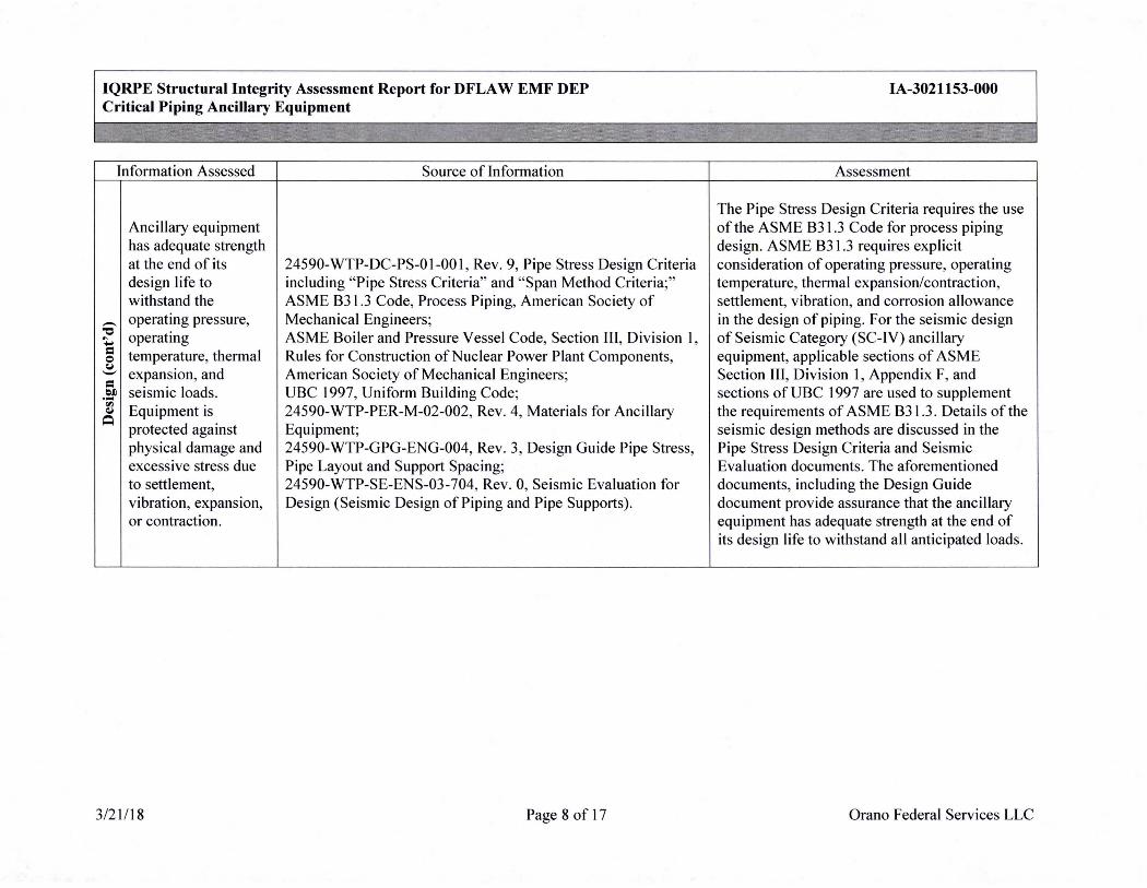
Ancillary equipment has adequate strength at the end of its 24590-WTP-DC-PS-01-001, Rev. 9, Pipe Stress Design Criteria design life to including "Pipe Stress Criteria" and "Span Method Criteria;" withstand the ASME B31.3 Code, Process Piping, American Society of
- operating pressure, Mechanical Engineers; "C operating ASME Boiler and Pressure Vessel Code, Section Ill , Division I, ~ -= temperature, thermal Rules for Construction of Nuclear Power Plant Components, Q CJ
expansion, and American Society of Mechanical Engineers; -= efl seismic loads. UBC 1997, Uniform Building Code; -~ ~ Equipment is 24590-WTP-PER-M-02-002, Rev. 4, Materials for Ancillary ~
protected against Equipment; physical damage and 24590-WTP-GPG-ENG-004, Rev. 3, Design Guide Pipe Stress, excessive stress due Pipe Layout and Support Spacing; to settlement, 24590-WTP-SE-ENS-03-704, Rev. 0, Seismic Evaluation for vibration, expansion, Design (Seismic Design of Piping and Pipe Supports). or contraction.
3/21/18 Page 8 of 17
IA-3021153-000
Assessment
The Pipe Stress Design Criteria requires the use of the ASME B3 \ .3 Code for process piping design. ASME B3 l .3 requires explicit consideration of operating pressure, operating temperature, thermal expansion/contraction, settlement, vibration, and corrosion allowance in the design of piping. For the seismic design of Seismic Category (SC-IV) ancillary equipment, applicable sections of ASME Section Ill , Division 1, Appendix F, and sections of UBC 1997 are used to supplement the requirements of ASME B3 \ .3. Details of the seismic design methods are discussed in the Pipe Stress Design Criteria and Seismic Evaluation documents. The aforementioned documents, including the Design Guide document provide assurance that the ancillary equipment has adequate strength at the end of its design life to withstand all anticipated loads.
Orano Federal Services LLC
IQRPE Structural Integrity Assessment Report for DFLA W EMF DEP Critical Piping Ancillary Equipment
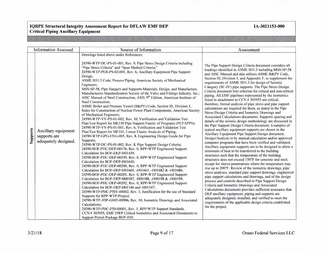
Information Assessed Source of Information Drawings listed above under References;
24590-WTP-DC-PS-01-001 , Rev. 9, Pipe Stress Design Criteria including " Pipe Stress Criteria" and "Span Method Criteria;" 24590-WTP-PER-PS-02-001 , Rev. 6, Ancillary Equipment Pipe Support Design; . . ASME 831.3 Code, Process Piping, American Society of Mechanical Engineers; . . MSS-SP-58, Pipe Hangers and Supports-Materials, Design, and Manufacture, Manufacturers Standardization Society of the Valve and Fittings Industry, Inc.; AISC Manual of Steel Construction, ASD, 9th Ed ition, American Institute of Steel Construction ; ASME Boiler and Pressure Vessel (B&PV) Code, Section III , Division I, Rules for Construction of Nuclear Power Plant Components, American Society of Mechanical Engineers; 24590-WTP-VV-PS-01-002, Rev. 10, Verification and Validation Test Plan/Test Report for ME 150 Pipe Support Family of Programs (PCFAPPS); 24590-WTP-VV-PS-01-001 , Rev. 6, Verification and Validation Test
"' Ancillary equipment Plan/Test Report for ME IO I, Linear Elast ic Analys is o_f Pipin_g; . -I. 0
supports are 24590-WTP-GPG-ENG-005, Rev. 8, Engineering Design Guide for Pipe C. C.
Supports; . . . = adequately designed. r,i 24590-WTP-DC-PS-01-002, Rev. 8, Pipe Support Design Criteria; 24590-BOF-PHC-DEP-00176, Rev. 0, RPP-WTP Engineered Support Calculation for BOF-DEP-H0 1439; 24590-BOF-PHC-DEP-00195, Rev. 0, RPP-WTP Engineered Support Calculation for BOF-DEP-H0l640; 24590-BOF-PHC-DEP-00200, Rev. 0, RPP-WTP Engineered Support Calculation for BOF-DEP-H01660, -H01661 , -H01682 &-H0l686; 24590-BOF-PHC-DEP-00201 , Rev. 0, RPP-WTP Engineered Support Calculation for BOF-DEP-H00187, -H00188, -H00198 & -H00199; 24590-BOF-PHC-DEP-00202, Rev. 0, RPP-WTP Engineered Support Calculation for BOF-DEP-H0l 146 and -H0l 147; 24590-WTP-PHC-P50T-00002, Rev. I, Justification for the use of Standard Supports for RPP-WTP-Project; . 24590-WTP-3DP-G04T-00906, Rev. 10, Isometric Drawings and Associated Calculations; 24590-WTP-PHC-PS0-0000 1, Rev. I, RPP/WTP Support Standards. CCN # 303955, EMF DWP Critical Isometrics and Associated Documents to Support Permit Package BOF-010.
3/21/18 Page 9 of 17
IA-3021153-000
Assessment
The Pipe Support Design Criteria document considers all loadings identified in ASME 831.3 including MSS-SP-58 and AISC Manual and also utili zes ASME B&PV Code, Section Ill , Division I, and Appendix F, to supplement the requirements of ASME 831 .3 for design of Seismic . Category (SC-JV) pipe supports. The Pipe Stress Desi~~ Criteria document li sts criterion for critical and non-critical piping. All EMF pipelines represented by the isometrics listed in attachment to CCN # 303955 are critical, therefore, formal analysis of pipe stress and pipe support calculations are required for them, as stated in the Pipe Stress Design Criteria and Isometric Drawings and Associated Calculations documents. Supports spacing and details of the seismic design methodology are di scussed in the Pipe Support Design Criteria document. Examples of typical ancillary equipme_nt supports are shown in the Ancillary Equipment Pipe Support Design document. Design/Analysis is by manual calculation and/or approved computer programs that have been verified and validated. Ancillary equipment supports are to be designed to allow a minimum of heat to be transferred to the building structures such that the temperature of the building structures does not exceed 150°F for concrete and steel, except for sleeve penetrations where th~ tempe~ature ~ay rise up to 200°F. Review of the isometric drawings, pipe stress analyses, standard pipe support drawings, engineered pipe support calculations and drawings, and of the ~esign process and controls described in Pipe Support Design Criteria and Isometric Drawings and Associated Calculations documents provides sufficient assurance that DEP ancillary equipment; piping and supports are adequately designed, installed, and verified to meet the requirements of the applicable design criteria established for the project.
Orano Federal Services LLC

IQRPE Structural Integrity Assessment Report for DFLA W EMF DEP Critical Piping Ancillary Equipment
Information Assessed Source of Information
"' = Drawings listed above under References· -~ The system will - ' 1:11 withstand the effects "O
= of frost heave. 24590-WTP-DC-ST-01-001 , Rev. 13, Structural Design
= 0 Criteria. ~
~4590~W:.P~DC-PS-01-001, Rev. 9, Pipe Stress Design Criteria mcludmg Pipe Stress Criteria" and "Span Method Criteria;"
"' = ASME B3 1.3 Code, Process Piping, American Society of -~ Seams and Mechanical Engineers; -(,I ~ connections are AS~E B 16.5, Piping Flanges and Flanged Fittings, American = = adequately designed. Society of Mechanical Engineers; 0 u ASM~ Boiler and _Pressure Vessel Code (B&PV), Section IX,
Welding and Brazmg Qualifications, American Society of Mechanical Engineers.
3/21/18 Page 10 of 17
IA-3021153-000
Assessment
The Structural Design Criteria requires that all outdoor equipment structural foundations shall extend into the surrounding soil below the 30" frost line to preclude frost heave. The DEP ancillary equipment system considered in this assessment are located inside the DFLA W facility rooms, at above ground floor slab elevation, as shown on the drawings therefore
' ' they are not subjected to any frost heave effects.
The Pipe Stress Design Criteria specifies the ASME B31.3 Process Piping design code for the piping systems. Welding is to be performed in accordance with the requirements of ASME B31.3 and the ASME B&PV Code, Section IX. ASME B 16.5 is specified for flange designs. These are appropriate and adequate codes and standards for design and fabrication including, connections and seams of the DEP system ancillary equipment.
Orano Federal Services LLC
IQRPE Structural Integrity Assessment Report for DFLA W EMF DEP Critical Piping Ancillary Equipment
Information Assessed Source of Information
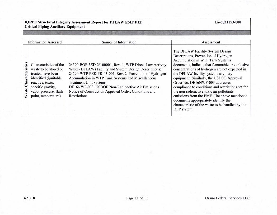
"' -~ Characteristics of the 24590-BOF-3ZD-25-0000I , Rev. I, WTP Direct Low Activity -"' waste to be stored or Waste (DFLA W) Facility and System Design Descriptions; ·c: ~ treated have been 24590-WTP-PER-PR-03-001 , Rev. 2, Prevention of Hydrogen -(J co: identified (ignitable, Accumulation in WTP Tank Systems and Miscellaneous I. co: reactive, toxic, Treatment Unit Systems; -= u specific gravity, DE 16NWP-003, US DOE Non-Radioactive Air Emissions ~ - vapor pressure, flash Notice of Construction Approval Order, Conditions and "' co:
~ point, temperature). Restrictions.
3/21/18 Page 11 of 17
IA-3021153-000
Assessment
The DFLA W Facility System Design Descriptions, Prevention of Hydrogen Accumulation in WTP Tank Systems documents, indicate that flammable or explosive concentrations of hydrogen are not expected in the DFLA W facility systems ancillary equipment. Similarly, the USDOE Approval Order No. DE I 6NWP-003 addresses compliance to conditions and restrictions set for the non-radioactive toxic air pollutants emissions from the EMF. The above mentioned documents appropriately identify the characteristic of the waste to be handled by the DEP system.
Orano Federal Services LLC
IQRPE Structural Integrity Assessment Report for DFLA W EMF DEP Critical Piping Ancillary Equipment
-
Information Assessed Source of Information
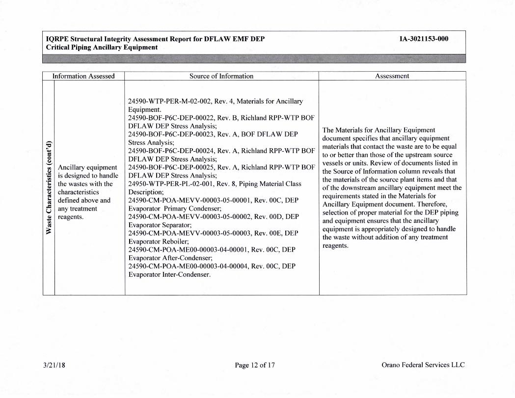
24590-WTP-PER-M-02-002, Rev. 4, Materials for Ancillary Equipment. 24590-BOF-P6C-DEP-00022, Rev. B, Richland RPP-WTP BOF DFLA W DEP Stress Analysis; 24590-BOF-P6C-DEP-00023, Rev. A, BOF DFLA W DEP - Stress Analysis; "O ... 24590-BOF-P6C-DEP-00024, Rev. A, Richland RPP-WTP BOF = Q DFLA W DEP Stress Analysis; ~
'-' Ancillary equipment ,,., 24590-BOF-P6C-DEP-00025, Rev. A, Richland RPP-WTP BOF
~ ~ is designed to handle DFLA W DEP Stress Analysis; ,,., ·t: the wastes with the 24950-WTP-PER-PL-02-00 I, Rev. 8, Piping Material Class ~ - characteristics ~ Description; cs I. defined above and 24590-CM-POA-MEVV-00003-05-00001, Rev. 00C, DEP cs -= u any treatment Evaporator Primary Condenser; ~ reagents. 24590-CM-POA-MEVV-00003-05-00002, Rev. 00D, DEP -,,., cs Evaporator Separator; ~ 24590-CM-POA-MEVV-00003-05-00003, Rev. 00E, DEP
Evaporator Reboiler; 24590-CM-POA-ME00-00003-04-00001 , Rev. 00C, DEP Evaporator After-Condenser; 24590-CM-POA-ME00-00003-04-00004, Rev. 00C, DEP Evaporator Inter-Condenser.
3/21/18 Page 12 of 17
IA-3021153-000
Assessment
The Materials for Ancillary Equipment document specifies that ancillary equipment materials that contact the waste are to be equal to or better than those of the upstream source vessels or units. Review of documents listed in the Source of Information column reveals that the materials of the source plant items and that of the downstream ancillary equipment meet the requirements stated in the Materials for Ancillary Equipment document. Therefore, selection of proper material for the DEP piping and equipment ensures that the ancillary equipment is appropriately designed to handle the waste without addition of any treatment reagents.
Orano Federal Services LLC

IQRPE Structural Integrity Assessment Report for DFLA W EMF DEP Critical Piping Ancillary Equipment
Information Assessed Source of Information
The pH range of the waste, waste temperature, and the corrosion behavior of the structural materials are adequately addressed . Anci llary equipment material and
i protective coatings ensure the ancillary :.6 equipment structure
24590-WTP-DB-ENG-01-001 , Rev. 6, Basis of Design; -.::: 24590-WTP-PER-M-02-002, Rev. 4, Materials for Ancillary ~
is adequately Q.,
= protected from the Equipment.
0 u corrosive effects of the waste stream and external environments. The protection is sufficient to ensure the equipment will not leak or fail for the design life of the system.
3/21/18 Page 13 of 17
IA-3021153-000
Assessment
The Basis of Design document identifies a service design life of 40 years for the ancillary equipment. Detailed materials selection with corrosion evaluations are conducted for each vesse l in the EMF faci lity during process design to assure a 40-year service life. The Materials for Ancillary Equipment document requires that the material selection and corrosion/erosion al lowances for ancillary equipment in contact with the waste will be equal to or better than the material and corrosion allowance of the waste source vessel. The evaluation in the Waste Characteristics section above discusses the review of the sources plant units materials and that of the downstream piping equipment with a conclusion that the EMF ancillary equipment will provide the expected design service life same as provided by the associated vessels.
Orano Federal Services LLC
IQRPE Structural Integrity Assessment Report for DFLA W EMF DEP Critical Piping Ancillary Equipment
·,
Information Assessed Source of Information
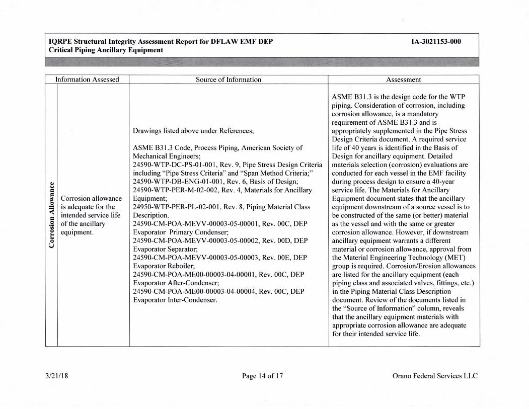
Drawings listed above under References;
ASME B31.3 Code, Process Piping, American Society of Mechanical Engineers; 24590-WTP-DC-PS-01-001, Rev. 9, Pipe Stress Design Criteria including "Pipe Stress Criteria" and "Span Method Criteria;"
~ 24590-WTP-DB-ENG-01-001 , Rev. 6, Basis of Design; C,I
24590-WTP-PER-M-02-002, Rev. 4, Materials for Ancillary = ~
~ Corrosion allowance Equipment; .£ is adequate for the 24950-WTP-PER-PL-02-00 I, Rev. 8, Piping Material Class < = intended service life Description. Q of the ancillary 24590-CM-POA-MEVV-00003-05-0000 I, Rev. 00C, DEP ·;; Q equipment. Evaporator Primary Condenser; '-'- 24590-CM-POA-M EVV-00003-05-00002, Rev. 00D, DEP Q u Evaporator Separator;
24590-CM-POA-MEVV-00003-05-00003, Rev. 00E, DEP Evaporator Reboiler; 24590-CM-POA-ME00-00003-04-0000 I, Rev. 00C, DEP Evaporator After-Condenser; 24590-CM-POA-ME00-00003-04-00004, Rev. 00C, DEP Evaporator Inter-Condenser.
3/21/18 Page 14 of 17
IA-3021153-000
Assessment
ASME B31 .3 is the design code for the WTP piping. Consideration of corrosion, including corrosion allowance, is a mandatory requirement of ASME B31.3 and is appropriately supplemented in the Pipe Stress Design Criteria document. A required service life of 40 years is identified in the Basis of Design for ancillary equipment. Detailed materials selection (corrosion) evaluations are conducted for each vessel in the EMF facility during process design to ensure a 40-year service life. The Materials for Anci llary Equipment document states that the ancillary equipment downstream of a source vessel is to be constructed of the same (or better) material as the vessel and with the same or greater corrosion allowance. However, if downstream ancillary equipment warrants a different material or corrosion allowance, approval from the Material Engineering Technology (MET) group is required. Corrosion/Erosion allowances are listed for the ancillary equipment (each piping class and associated valves, fittings, etc.) in the Piping Material Class Description document. Review of the documents listed in the "Source of Information" column, reveals that the ancillary equipment materials with appropriate corrosion allowance are adequate for their intended service life.
Orano Federal Services LLC

IQRPE Structural Integrity Assessment Report for DFLA W EMF DEP Critical Piping Ancillary Equipment
Information Assessed Source of Information
Pressure controls "' (vents and relief 0 I. valves) are - 24590-WTP-DC-PS-01-001 , Rev. 9, Pipe Stress Design Criteria = 0 adequately designed u to ensure pressure
including "Pipe Stress Criteria" and "Span Method Criteria;" ~ ASME B31.3 Code, Process Piping, American Society of I.
relief if normal = "' Mechanical Engineers. "' operating pressures in ~ I.
the vessels are ~
exceeded.
3/21/18 Page 15 of 17
IA-3021153-000
Assessment
The Pipe Stress Design Criteria document specifies ASME B3 1.3 as the design code for the WTP piping. ASME B31.3 requires provision be made to safely contain or relieve any pressure to which the piping may be subjected. ASME B31.3 piping not protected by a pressure relieving device, or that can be isolated from a pressure relieving device must be designed for at least the highest pressure that can be developed . Compliant to the above listed documents ensures that the ancillary equipment is adequately designed to sustain any above normal operating pressure in the vessels.
Orano Federal Services LLC
IQRPE Structural Integrity Assessment Report for DFLA W EMF DEP Critical Piping Ancillary Equipment
... ~ .. ~
lnformation Assessed Source of Information
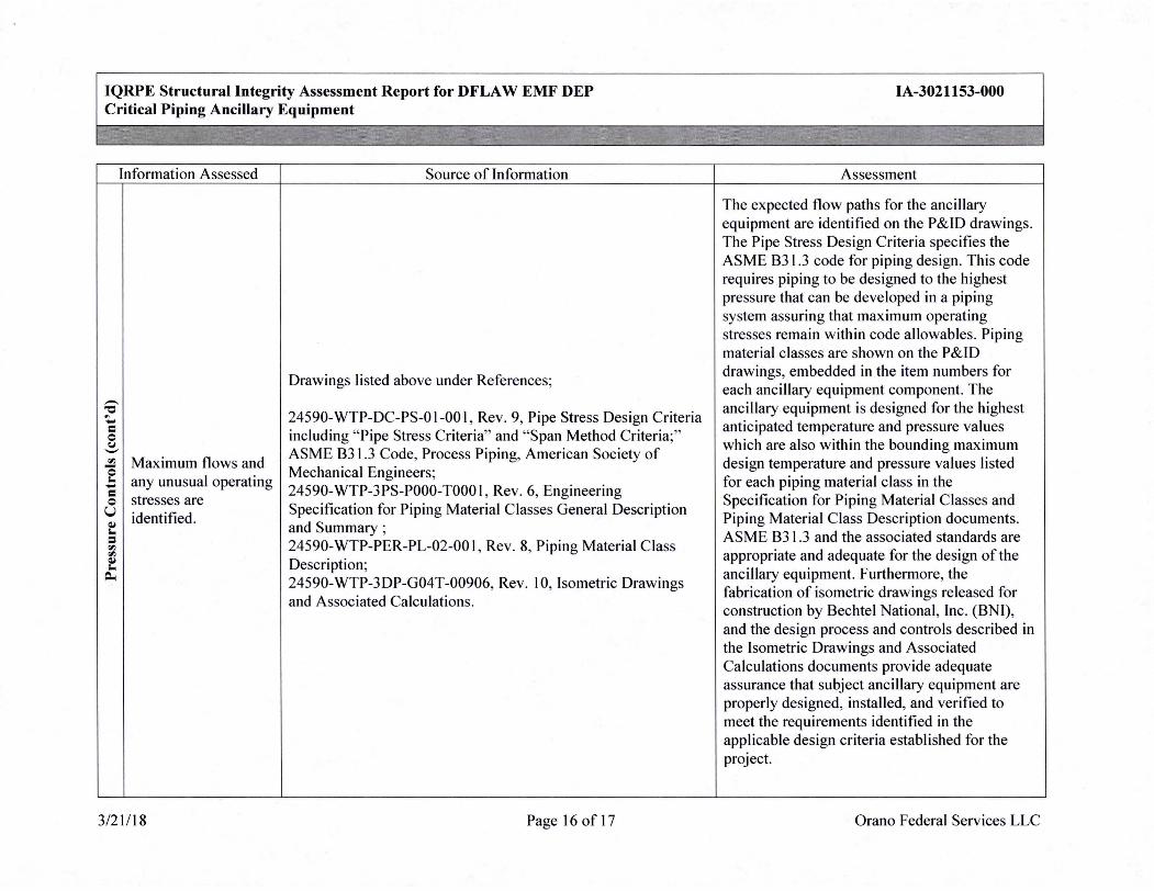
Drawings listed above under References· ' -"O
~ 24590-WTP-DC-PS-01-001 , Rev. 9, Pipe Stress Design Criteria -= 0 including "Pipe Stress Criteria" and "Span Method Criteria;" (.I - ASME 83 1.3 Code, Process Piping, American Society of "' Maximum flows and Q Mechanical Engineers; i.. any unusual operating - 24590-WTP-3PS-P000-T000I, Rev . 6, Engineering = 0 stresses are u identified.
Specification for Piping Material Classes General Description Q,I i.. and Summary ; = "' 24590-WTP-PER-PL-02-00 I, Rev. 8, Piping Material Class "' Q,I i.. Description;
Po. 24590-WTP-3DP-G04T-00906, Rev. 10, Isometric Drawings and Associated Calculations.
3/21/18 Page 16 of 17
IA-3021153-000
Assessment
The expected flow paths for the ancillary equipment are identified on the P&ID drawings. The Pipe Stress Design Criteria specifies the ASME 831.3 code for piping design . This code requires piping to be designed to the highest pressure that can be developed in a piping system assuring that maximum operating stresses remain within code allowables. Piping material classes are shown on the P&ID drawings, embedded in the item numbers for each ancillary equipment component. The ancillary equipment is designed for the highest anticipated temperature and pressure values which are also within the bounding maximum design temperature and pressure values listed for each piping material class in the Specification for Piping Material Classes and Piping Material Class Description documents. ASME 831.3 and the associated standards are appropriate and adequate for the design of the ancillary equipment. Furthermore, the fabrication of isometric drawings released for construction by Bechtel National, lnc. (BNI), and the design process and controls described in the Isometric Drawings and Associated Calculations documents provide adequate assurance that subject ancillary equipment are properly designed, installed, and verified to meet the requirements identified in the applicable design criteria established for the project.
Orano Federal Services LLC

IQRPE Structural Integrity Assessment Report for DFLA W EMF DEP Critical Piping Ancillary Equipment
Information Assessed Source of Information
Ancillary equipment Drawings listed above under References;
is designed with secondary
24590-WTP-3PS-NLLR-T0002, Rev. I, Engineering . containment that is
Specification for Furnishing, Detail!ng, Fabrication, Delivery - constructed of C and Installation of Stainless Steel Lmer Plates; Q,I
e materials compatible 24590-WTP-3PS-AFPS-T0006, Rev. 3, Engineering C
with the waste and of Specification for Field Applied Special Protective Coatings for ·; - sufficient strength to C Secondary Containment Areas; 0
prevent failure 24590-WTP-PER-CSA-02-001 , Rev. 11 , Secondary u
t (pressure gradients, Containment Design; . . . ~
waste, climatic 24590-BOF-PER-M-16-001, Rev. 0, Leak Detection Capability
"C C 0 conditions, daily
in the EMF Facility; . . (,.j Q,I operations), provided
24590-BOF-PER-M-16-002, Rev. 0, Waste Remov~I _Capability rJl with a leak-detection
for the Direct Feed LAW Effluent Management Facility (EM~); system, and designed
24590-BOF-M0C-DEP-0000 I, Rev. B, Liner Height Calculat10n to drain and remove
in the EMF. liquids.
3/21/18 Page 17 of 17
IA-3021153-000
Assessment
The EMF facility DEP system ancillary equipment considered in this assessment runs between various plant items as shown on the drawings. The secondary containment for the ancillary equipment and the associated vessels and plant items is provided by stainless steel liner plates and has numerous sumps as shown on the general arrangement drawings and in the Leak Detection Capability document. The removal of leaked waste is accomplished per the Waste Removal Capability document. The design and installation of secondary containment stainless steel liner plates and special protective coatings are accomplished per the documents listed in the Source of Information column. The secondary containment stainless steel liner plates are anchored to the concrete floor and wall structures of the EMF facility. The structural integrity assessment of the above mentioned_ concrete structures is outside the scope of this assessment; however, it is conducted in a separate document titled, " IQRPE Structural Integrity Assessment Report for LAW DFLA W EMF Secondary Containment."
Orano Federal Services LLC