radan napověda anglicky ok
TRANSCRIPT
Recent enhancements31.1.01
30.3.01
30.1.01
29.3.01
29.1.01
28.3.01
28.1.03
28.1.01
27.3.01
27.1.01
26.3.01
26.1.01
Issue 31.1.01
Area Title DetailsGeneral Windows 8 The software may now be installed on Windows 8.General File name length The names of drawings, symbols and assemblies may now
have up to 125 characters.General Material name length Material names for sheets and parts may now have up to
100 characters. This is a significant increase from theprevious limit of 20 characters.
3D ACIS upgrade The version of the Spatial ACIS component used by the3D software has been upgraded to Release 22 Service Pack2, and the Parasolid kernel has been upgraded to version24.0.133. This is necessary so that models created usingthe latest versions of various CAD packages may beimported into 3D. In particular, 3D now supports importand export of R22 SAT files, import of version 24Parasolid files, and import of R21 CATIA V5 files.
When you export a SAT file, the Options dialog nowallows the version to be specified simply as 'latest' to usethe most up to date SAT version that the softwaresupports.
3D Import files using dragand drop
3D models may now be imported using drag and drop. Theapplication must be in 3D mode or Top Level mode whenyou 'drop' the file onto it (in the case of a 3D IGES file, it
Stránka . 1 z 34Recent enhancements
4.8.2013file:///C:/Users/Dante/AppData/Local/Temp/~hhB617.htm
must be in 3D mode). The model will be imported usingthe current workspace and import settings, including the'Calculate thickness' option. If appropriate, you will beprompted to enter a default material for the model. In thecase of an Inventor model, the default material that you setwill be overridden if a material is specified in the file.
3D Radbend link The link between Radan and Radbend has been improvedto give a more integrated workflow when editing a modelwith both applications.
It is now possible to open Radbend Cad4Cam files (withthe .c4cx extension) in Radan using the Open Drawingdialog. If you do not have Radbend installed, Radbendinformation in the file will not be used, but the informationwill be preserved without change if the drawing is then re-saved as a Cad4Cam file.
Drafting Jump region to cursor The jump to cursor command now has an option in theSelection Settings area to select a region. A region may beany closed profile of lines and arcs, possibly containingother closed profiles that define holes. First indicate theanchor point, then select the region simply by clickinganywhere inside it. Smart Select will highlight the linesand arcs that will be jumped to the cursor.
This option is also available when you grab features fromthe drawing into the Part Editor.
Nesting Single part nesting The Single Part Nests and Pre-Cut Blanks dialog has beenimproved. Normally, the dialog now starts a new drawingto contain the nest, instead of modifying the currently opendrawing. It is still possible to make changes to an existingsingle-part nest using this dialog (e.g. to adjust theclearances), by using the Nest > Modify Single Part Nestmenu option to display the dialog.
The dialog now has an Overproduce option. When thisoption is turned off, the number of parts nested will notexceed the number you specify in the Batch field. If thebatch number is less than the number of parts that wouldfill up the sheet, the sheet will be only partially filled withparts.
If you are using a nest project, the Single Part Nests andPre-Cut Blanks dialog is now accessed using a button inthe Parts tab of the bottom splitter window. The part thatyou want to nest must be selected in the parts list first.Normally, the sheet sizes shown in the dialog are theremaining unused sheets in the project's sheets list,although you also have the option to choose from all yourstandard sheet sizes. When you accept a nest and close thedialog, the nest will be saved immediately in the projectnest folder.
Nesting Colour coding of partsin nest projects
If you are using a nest project, parts in nests may now bedisplayed using different fill colours. To switch this on,
Stránka . 2 z 34Recent enhancements
4.8.2013file:///C:/Users/Dante/AppData/Local/Temp/~hhB617.htm

select the View > Colour Fill > Multi-colour Parts option.By default, a different colour is used for each item in theparts list, but you may choose instead to show all parts thatshare a common property with the same colour. Forexample, you might show high-priority parts in a differentcolour from parts with normal priority. To control this, usethe Colour By option on the context menu (i.e. the rightmouse button) of the parts list in the bottom splitterwindow. The maximum number of colours available is 32:if more are needed then the same 32 are reused.
The fill colours used in the graphics are also used whenyou print the nest, and in the HTML setup sheet when youcompile blocks for the nest. If the View > Colour Fill >Multi-colour Parts option is not selected, multiple coloursare not used in the graphics or when printing, but are stillused in the HTML setup sheet.
Printing Hatching of colour-filled parts
When printing a nest, the Print dialog has an option todraw colour-filled parts with hatching instead of solidcolour, to reduce ink usage. The Setup Sheet page of theMachine Configuration Editor provides a similar optionfor the HTML setup sheet.
Tooling Multi-tools The software's support for multi-tools on punchingmachines has been improved. Formerly, the turret stationsinto which multi-tools were loaded was fixed in systemdata. The new design allows a multi-tool to be loaded intoany suitable station of the machine's turret, and you canconfigure this easily in the Tool Library Editor. Existingusers do not have to change their way of working, unlessthey want the extra flexibility, because the new design iscompatible with the old methods.
A multi-tool is modelled as a type of tool which can havesimple tools loaded into it. Like any other tool, a multi-toolhas a tool number and it appears in the list of availabletools in the Tool Library Editor. When you add or edit atool of this type, the Add Multi-tool or Edit Multi-tooldialog is shown. This dialog has a similar design to themain Tool Library Editor, allowing simple tools to beloaded into the available stations of the multi-toolassembly using drag and drop. These represent pre-loadedtools, i.e. tools which that multi-tool normally contains.
The Tool Library Editor itself shows the stations of themachine's turret. Multi-tools may be loaded into suitablestations using drag and drop. When a multi-tool is loaded,the stations and pre-loaded tools within the multi-tool canoptionally be viewed as well (they are listed on a greybackground).
Whenever the software needs to allocate tools to turretstations (e.g. when you run autotooling or enter OrderMode), it will only use a multi-tool if your Standard Tool
Stránka . 3 z 34Recent enhancements
4.8.2013file:///C:/Users/Dante/AppData/Local/Temp/~hhB617.htm
Issue 30.3.01
Loading (STL) specifies it. Unlike simple tools, multi-tools that are not in the STL will not be usedautomatically.
The Tooling tab of the Machine Configuration Editor has anumber of options for controlling the use of multi-tools.
Configuration Options added todialogs
A few configuration options which were formerly difficultto view or modify have now been made visible in dialogs.
The 'Common cutting in part order' option is in theCommon Slitting tab of the Order Preferencesdialog. For nests with common cutting, this optioncauses Order Mode to cut all the profiles of aparticular part before moving on to the next part.The 'Pens to ignore in nesting' option is in the Penstab of the Machine Configuration Editor. Whendrawing parts in the Part Editor, lines and arcs withthose pen numbers will be ignored by the closedgeometry check, the Single Part Nests and Pre-CutBlanks facility, and the Constrain feature in manualnesting. (The Multi-Part Nesting dialog has its ownindependent list of pens to ignore.)For machine tools that have a loader or unloader, theLoader/Unloader tab of the Machine ConfigurationEditor allows the type number to be changed. Themeaning of the type number depends on yourmachine tool.If your block compiler is configured to allow it, theMachine Configuration Editor will have a Compilertab with a number of advanced options for thecompiler. The details will depend on your blockcompiler.If your block compiler is configured to allow it, theMachine Configuration Editor will have a PartPicker tab with a number of advanced optionsrelating to the picker. The details will depend onyour block compiler.
COMinterface
Mac object in the API A Mac object has been added to the ApplicationProgramming Interface (API) for use by VBA macrosand .NET plug-ins. The Mac object provides a directinterface onto a large number of MAC language functionsand variables. The Mac object's method names, methodarguments and property names are exactly the same asthose used for the corresponding MAC language functionsand variables, so many of them will be familiar toexperienced macro writers.
Area Title Details3D Face selection for When transferring a part from 3D to Radbend, a face is
Stránka . 4 z 34Recent enhancements
4.8.2013file:///C:/Users/Dante/AppData/Local/Temp/~hhB617.htm
Radbend transfer now selected automatically. The user may select adifferent face if the one selected by default is not suitable(a Pick button is provided for this). The selected face isremembered so that subsequent transfers of the same partare based on the same coordinate system. This will makeparametric programming in Radbend easier.
3D SolidWorks 2012import
SolidWorks 2012 files may now be imported into 3D.
Drafting Selecting profiles indrafting
In drafting in the Part Editor and in 2D CAD, it is nowpossible to select profiles of lines and arcs for editing.Click the Profile button in the Settings area to enable this.The operations for which profiles may be selected are:delete, move, rotate, jump to cursor, grab into the PartEditor, corner repeat, mirror, pattern exchange, and editline and arc properties (for changing pen, line type, etc).
To be selected as a profile, a chain of lines and arcs withthe same pen and line type must be connected end-to-end.In 2D CAD, they must also belong to the same pattern.
Printing Printing when using awide-screen monitor
When printing a zoomed-in area of the drawing, the printis now centred on the paper. This matters when theapplication window is maximized on a wide-screenmonitor, causing the shape of the display to differsignificantly from the shape of the paper. If you want theprint to fill the paper, you may want to resize theapplication window temporarily to approximately matchthe shape of the paper.
Attributes Machine-specificattribute values
Certain drawing and part attributes which are important fortooling and Order mode now have machine-specificvalues. For these attributes, the values which are shown inthe Attributes dialog depend on which machine tool iscurrent, and a different value may be set for each machine.The numbers and names of the affected attributes are: 123Cycle time, 128 Order time, 129 Blocks time, 130 Verifytime, 131 Output time, 139 STL id, and 146 Strategy, andalso numbers 172 to 180 in the Cost Estimate group.
RadviewPlus, RadviewDNC and RadviewBatchPrint havebeen modified to take account of the machine-specificvalues of these attributes.
Tooling STL names Standard Tool Loadings (STLs), formerly identified bynumbers, may now be identified by name. In the ToolLibrary Editor, an STL name may be selected from a drop-down list, and text may be entered into the same control tocreate a new STL name. The default STL, which wasformerly numbered 0, is now named 'Default'. STL namesmay not contain spaces.
Sheet cutting Offcut tooling forpunching machines
The Sheet Scrapping and Offcuts dialog, formerlyavailable for profiling machines only, is now available forpunching machines as well, to allow offcut tooling to beadded to nests automatically. (Punch tooling may not beused for scrap cuts.) If you are using a combination
Stránka . 5 z 34Recent enhancements
4.8.2013file:///C:/Users/Dante/AppData/Local/Temp/~hhB617.htm
machine then you have a choice of whether to use profileor punch tooling for offcuts.
Nesting Single-part nesting The true-shape nester has been made better at nesting alarge quantity of a rectangular part (or approximatelyrectangular part), especially when the quantity is largeenough to completely fill the sheet with that part. In termsof the utilization achieved, the true-shape nester now out-performs the rectangular nester at this kind of nesting. TheSingle Part Nesting and Multi-Part Nesting facilities bothbenefit from this improvement.
Nesting Customized details innest project lists
It is now possible to choose which columns to display inthe Details view of each of the nest project splitterwindows, such as the nest project Parts list. The left toright ordering of the columns may also be changed. Usethe right mouse button to show the context menu of the listthat you want to customize, and select the ChooseColumns option. For the lists that show parts or drawings,columns may be turned on to show any of the part ordrawing attributes. If your system is set up to store'AdditionalInfo' with the part items in nest project files,columns may be turned on to show this information in theParts list.
Order mode Current Tool Loadinglist
The Current Tool Loading list in Order mode has beenredesigned to have a similar 'look and feel' to the Tools listin Part Editor Tooling mode. For punching andcombination machines, the list shows active stations bymeans of light bulb icons, and columns have been added toshow the tool sizes and to indicate which tools havefeatures still to cut. If stations have multiple load angles,you can choose to show each angle as a separate row orjust have one row for each station. Buttons in the splitterwindow make it easy to view the features in the nest for aselected station and angle, and to add Punch commands forjust those features.
For profiling machines, active cutting conditions areshown with light bulb icons, and columns show the cutwidth and indicate which cutting conditions have featuresstill to cut. A button in the splitter window makes it easy toview the features in the nest for a selected cuttingcondition.
In Nest Tooling mode, a tool list may be shown which issimilar to the one in Order Mode, although this only showstool usage in the nest and not tool loading information. Inall the modes, the performance of the tool list display hasbeen improved significantly.
The columns in these tool lists may be hidden orrearranged, like the columns in the nest project lists (seeabove).
Order mode Start corner forDirection command
A 'Start' keyword may now be added to the Directioncommand in Order mode. If present, the Start keyword
Stránka . 6 z 34Recent enhancements
4.8.2013file:///C:/Users/Dante/AppData/Local/Temp/~hhB617.htm
Issue 30.1.01
causes cutting to start at the first corner specified in theDirection command, instead of the corner closest to themachine head. The Cutting Direction dialog generates aDirection command with the Start keyword if you specifya particular corner to start cutting from.
Order mode Dynamic indexablemultitools
A number of internal software changes have been made toimprove its handling of dynamic indexable multitools, inOrder mode and in some postprocessors and verifiers. Forexample, auto-order is better able to rotate a multitool to asuitable angle for punching a circular hole near a clamp,without requiring a reposition.
Utility Store results of QuickEstimates
When using the Quick Estimates dialog in the Part Editor,there is now an option to store the calculated values in thepart's attributes. To set the attributes, close the dialog withthe 'Store and Close' button. The affected attributes are inthe Cost Estimate group. The attributes of the file on discare not modified until the part is saved in the normal way.
When using the Quick Estimates dialog for a nest or a nestproject, the calculated values may be stored in theattributes of the nest or nests concerned. Closing the dialogwith the 'Save and Close' button causes the attributes to besaved to the drawing files on disc.
Area Title DetailsGeneral New, Open and Save
buttonsThe New, Open and Save buttons on the Standard toolbarnow have menus, to make it easier to perform thesecommands with parts and with nest projects. For example,you can open a part while in the Nest Editor using the Newbutton's menu (which will cause an automatic switch intothe Part Editor). Simply clicking the button withoutdisplaying the menu has the same effect as in previousversions of the software.
3D Bend allowance inRadbend
RadbendCNC has been renamed Radbend in this release.
Bend allowance changes made to the model in Radbendcan now be passed back to Radan 3D, allowing moreaccurate blanks to be produced.
Drafting Repeated querying The 2D Query dialog now has a 'repeated query' button.This allows you to remain in querying mode for as long asthe button is pressed in (or until you close the Querydialog), so that you can query a series of features withouthaving to click the 'F' button for each one.
Printing Colour filling of partsand sheets
The Print dialog now has options for printing the colourfilling of sheets, parts and tooling. One benefit of this isthat it is easier to distinguish between parts and sheet holesin print-outs of nests made with remnant sheets.
Tooling List of tools in splitter In tooling mode in the Part Editor, a list of used tools is
Stránka . 7 z 34Recent enhancements
4.8.2013file:///C:/Users/Dante/AppData/Local/Temp/~hhB617.htm
window shown in a splitter window. The list of tools updatesautomatically and immediately as you make changes to thepart's tooling. Buttons in the splitter window make it easyto redraw just the features that use a selected tool, and todelete all those features from the part.
Tooling Bridge cutting For profiling machine tools, there is now a facility intooling mode for manually adding 'bridges' betweenprofiles. A bridge is formed with two linear slots. Either atag or an overlap may be created at the point where thebridge connects to the profiles.
Bridge slots can only join to profiles at mid-feature points,not at their corners. Currently, bridges can only be addedbetween profiles that have been autotooled. Bridgedprofiles must be cut using the Profile command in Ordermode; they cannot be cut using Subroutine or Copycommands.
Tooling Moving the orderdatum
The position of the order datum can now be set using theNew Sheet dialog and changed using the Sheet Propertiesdialog in the Nest Editor. The order datum may be placedat a corner or the centre of the rectangle defined by thesheet border clearances, the sheet, or the boundingrectangle of the parts. Formerly, the order datum wasalways placed at the bottom left corner of the rectangledefined by the sheet border clearances.
This facility is only available if it is allowed by your blockcompiler.
Autotooling Rules and styles forcorner and mid-linetags
For profiling machine tools, corner and mid-line taggingoptions may now be defined separately for each rule in theAutotooling Rules and Styles dialog. The main AutomaticTooling dialog has an option on its Tags page to use therule and style settings in preference to the settings shownon that page. In the Rules and Styles dialog, corner andmid-line tag styles are shown in the Styles list, and tag sizeand orientation options are available for every tag style.
When using Rules and Styles, rules may also be set up toadd a tag at the end of each profile (i.e. just before thelead-in point). An end tag defined in this way may beadded to profiles that also have corner tags or mid-linetags.
Autotooling Pens for centre-offsettooling
The Pens page of the Automatic Tooling dialog nowallows you to specify pen numbers for lines and arcs thatyou want to cut with centre-offset tooling.
Nesting Nest projects folderlocations
The New Project dialog now allows you to specify anyfolders you wish for storing the nest and remnant drawingsof a nest project. It is acceptable for nest and remnantdrawings to be saved together in the same folder, anddifferent projects may all use the same folder for theirdrawings. If you do not use remnants, the paths of theremnants folders may be left blank in this dialog.
Stránka . 8 z 34Recent enhancements
4.8.2013file:///C:/Users/Dante/AppData/Local/Temp/~hhB617.htm
Issue 29.3.01
The Nest Schedule Editor dialog has been renamed to theMulti-Part Nesting dialog, which is a more appropriatename when using the nest projects environment.
Nesting Editing properties ofseveral parts at once
When working with the parts list in the Multi-Part Nestingdialog or in a nest project, it is now possible to selectmultiple items in the list and edit their properties together.
Nesting Same-part common linecutting
When nesting parts with common line cutting, there is nowan option to restrict common cutting to be betweeninstances of the same part only. This is an alternative toallowing common cutting to occur between any two parts.When using the new option, it is also possible to define amaximum number of instances of the part in any onecommon-cut group. The nester tries to produce compactgroups of parts to maximize the amount of commoncutting in them.
Nesting Sheet priority When nesting using multiple sheet sizes, it is now possibleto specify a priority ordering for the sheets. The nester willmake nests with the sheets that have the highest priority,and it will only consider lower-priority sheets if is notpossible to make a nest with a high-priority sheet (e.g.,because no parts will fit). A priority may also be specifiedfor remnants, which applies equally to all remnant sheets.
Nesting Kits in nest projects When adding a part to a nest project, it is now possible tospecify that the part is a kit. Kits added to nest projectswill be expanded as they are added, so the parts containedin the kit will be added to the parts list instead of the kitsymbol itself.
Programoutput
Program Output dialog The Program Output window now has buttons that allowyou to view the nest drawing and the setup sheet. It alsohas a button to extract and execute the blocks file: theeffect of this may be to display the blocks in a text editoror send the blocks to the machine tool, depending on theWindows file association for blocks files on your system.
Programoutput
Colour filling in theHTML setup sheet
Images in the customizable HTML setup sheet now showcolour filling of the sheet, parts and tooling.
Area Title DetailsGeneral Technology upgrade The Microsoft compiler and other tools used for
developing the software have been upgraded to their latestversions. The software now targets version 4.0 of the .NETframework.
Several third-party components in the software have alsobeen upgraded to their latest versions, includingcomponents used for importing DWG and DXF files, andpackages used by the Radview software.
3D ACIS upgrade The version of the Spatial ACIS component used by the
Stránka . 9 z 34Recent enhancements
4.8.2013file:///C:/Users/Dante/AppData/Local/Temp/~hhB617.htm
3D software has been upgraded to Release 21 Service Pack2. This work is necessary so that models created using thelatest versions of various CAD packages may be importedinto 3D.
3D SolidWorks 2011import
SolidWorks 2011 files may now be imported into 3D.
3D Interpolated bendparameters warning
There is now an option to make the software give awarning if you attempt to unfold a model for which anybends do not have exact entries in the bend parameterstable (i.e. any bends for which interpolated values must beused). To turn this option on, set thehigh_precision_unfolding item to y in your bsys_usersystem data file.
DWG andDXF
Options in Import Partsdialog
It is now possible to change the DWG and DXF importoptions when using the Import Parts dialog to import filesinto the nest schedule. The Add button in the Import Partsdialog displays a file browser which includes the list ofconversion templates and gives access to the importoptions. The import options may also be accessed from the2D Conversion tab of the dialog. Using the 2D ImportOptions dialog, you can create or change a namedtemplate, or change your default conversion settings. Notethat all parts that are imported without a specific templatewill use the same default settings.
DWG andDXF
Filter imported data bylayer
The 2D Import Options dialog now allows you to selectparticular layers to import from a DWG or DXF file. Thelayers must be specified by name, so you will need toknow the names of the required layers in advance.
Graphics Shiny metal effect andcolour filled sheets
Colour-filled parts are now displayed with a shiny,metallic appearance in Nest mode and the Part Editor'sTooling mode. Sheets may now be displayed with a colourfill in Nest mode, optionally with a shiny appearance aswell. These graphical effects may be turned on or off usingthe Colour Fill options on the View menu.
The amount of shininess for parts and sheets and the sheetfill colour may be set in the Machine Graphics tab of theColour Preferences dialog. Appropriate defaults may beused by choosing a graphics theme in the Themes tab.
Graphics Greater choice ofcolours
All the colours defined in the Drafting Aids and MachineGraphics tabs of the Colour Preferences dialog may nowbe set to any colour you like. Formerly, they were limitedto the sixteen colours used for the pens.
Nesting Nesting discs The true shape nester has been enhanced to produce betternests of circular parts, and of parts that are approximatelycircular.
Nesting Picking clusters For machine tools that have part pickers, the true shapenester allows parts to be nested in picking clusters again.This functionality was temporarily removed from thesoftware in version 28.3.01 because of the introduction ofthe new nesting engine.
Stránka . 10 z 34Recent enhancements
4.8.2013file:///C:/Users/Dante/AppData/Local/Temp/~hhB617.htm
Nesting Remnant utilizationpremium
When using remnant sheet drawings in automatic nesting,you may define a 'premium' to add to the utilization of allnests made with remnants. This makes the nester use aremnant in preference to a stock sheet, if doing so does nothave a large cost in material utilization. This functionalitywas temporarily removed from the software in version28.3.01 because of the introduction of the new nestingengine.
Nesting Exclude selected partsand sheets from nesting
When using Nest Projects, it is now possible to excludeselected parts and sheets from automatic nesting. Thisfeature may be useful if you want to run the automaticnester a number of times with different combinations ofparts and sheets, or if you use a mixture of manual andautomatic nesting and you want to nest certain partsmanually.
To exclude a part or sheet from automatic nesting, selectthe item (or items) in the part or sheet list of the NestProject interface, and then use the Exclude From Nesteroption in the context menu (the 'right mouse' menu). Reddiamond icons indicate which list items are excluded.
Nesting Releasing remnants tothe Remnants to Usefolder
Some new facilities are available in the Nest Projectsinterface, particularly for managing remnants.
All the remnants in the Remnants Made list maynow be copied to the Remnants to Use folder simplyby clicking a 'Release' button on the Remnants Madetab. A confirmation notice is shown, because youwould normally only do this when you finishworking on a particular project. Remnants that havebeen released in this way are indicated in theRemnants to Use list with a 'copy' icon.Remnants may now be deleted from the Remnants toUse list by using an option in the context menu.There is now a Refresh option on the File > Projectmenu which reloads all the Nest Project lists. This isuseful if another user has changed the contents ofthe Remnants to Use folder.When you define the Remnants to Use folder in theProject Properties dialog, it may now be selectedfrom a list of recently used folders.When you define the project location folder in theNew Project dialog, it may now be selected from alist of recently used folders.
Nesting Counting parts in multi-part symbols
A multi-part symbol (also known as a rigid kit) is a symbolthat contains a number of other part symbols in a particularnested arrangement. When using Nest Projects, thequantities shown in the parts list may now be counted forthe parts contained in multi-part symbols, instead ofcounting the multi-part symbols themselves. To do this,add the contained parts to the parts list, but do not add themulti-part symbols themselves to the parts list. (If you adda multi-part symbol to the parts list, it will be counted
Stránka . 11 z 34Recent enhancements
4.8.2013file:///C:/Users/Dante/AppData/Local/Temp/~hhB617.htm
Issue 29.1.01
instead of the parts it contains.)
To be used in this way, multi-part symbols would normallybe nested manually or by using the Single Part Nestingdialog. The automatic nester will not nest them if they arenot in the parts list.
Unloading Overriding themaximum stack height
When unloading, you are now given the option ofoverriding the maximum stack height if you are starting anew bin. This allows you to make more than one stack, soyou can unload more parts than would be allowed in asingle stack.
Area Title Details3D Names of imported
partsWhen importing parts into 3D, the default names of theparts are now obtained from the imported data wherepossible, instead of using the names 'Part1', 'Part2', etc.
DWG andDXF
Importing directly tothe nest schedule
A new dialog is available for importing multiple 2D DWGand DXF files and adding them to the nest schedule asparts. The dialog allows you to specify where theconverted part files should be saved, to define the materialproperties and quantities of the parts, and to add themdirectly to the current nest schedule. The utility is availablefrom the Parts to Nest page of the Nest Schedule Editorand from the Parts area of the Nest Projects interface.
Tooling Angle of selected tool When selecting a tool from the Select Tool dialog forsingle hits, linear step & repeats or arc step & repeats, ifthe tool is selected from the Standard Tool Loading list inthe dialog, the load angle is now used to set the angle ofthe tool.
Tooling Tool Library Editordialog
When opening the Tool Library Editor or the Select Tooldialog, whether or not the Standard Tool Loading list isdisplayed is remembered from the last time the dialog wasused.
Tooling Selection of tools toedit
If you are using a machine tool for which the AdvancedTooling Options dialog is available when editing tooling,the edits may now be applied to several tooling features atonce by using window selection options in the Settingsarea of the GUI in the usual way. Formerly only onetooling feature at a time could be edited when using thisdialog.
Nesting Multi-threaded nestingcode
The true shape nesting software is now fully multi-threaded. This means that on a computer with a modern,multi-core processor, the nester uses all the availableprocessing power when it is searching for the bestarrangement of parts on the sheet.
Multi-threading is not used by rectangular nesting, orwhen the 'Check tools' option is turned on.
Stránka . 12 z 34Recent enhancements
4.8.2013file:///C:/Users/Dante/AppData/Local/Temp/~hhB617.htm
Issue 28.3.01
Nesting Program reduction The program reduction facility is now available for thenew true shape nester. This gives the option of reducingthe number of nest drawings created in a nesting run, byincreasing the number of duplicate sheets of each nest.
Nesting Nest projects warningicon
When using the Nest Projects interface, if a part in theparts list has a problem with its geometry that may preventthe part from being nested, a warning icon is nowdisplayed in the list.
Nesting PDF nest projectreports
When using the Nest Projects interface, there is now afacility for creating 'nest project reports' in PDF format. Itis accessed from a button in the Nests area of the interface.The reports are generated using customizable templatefiles in XSL format. Several such template files areprovided for producing various different reports on thematerials, parts and nests used and created in nest projects.
Order mode Reclamp devices onmetal
If reclamp devices are placed on loose areas of metal (thathave been cut free from the sheet), a warning is now given.
If Automatic Order causes a reposition, it will, if possible,find a position for the reclamp devices that avoids looseareas of metal.
Utility Cost estimate utility A utility has been added for calculating a cost estimate fora part, a nest, or for a set of nests in a nest project. TheQuick Estimates utility is accessed from the Utilitiesmenu.
When used in the Part Editor, the Quick Estimates utilitycalculates a cost estimate for the current part, and in NestModify mode it calculates an estimate for the current nest.If the Nest Projects interface is in use, the cost estimate iscalculated for all the nests in the open project. Theestimate is calculated from a number of cost elementsincluding the material cost, labour cost and the cost ofrunning the machine tool. Defaults for each machine maybe set up using the Machine Configuration Editor.
Plug-ins Plug-ins in .NETlanguages
Plug-ins may now be written in any of the .NETprogramming languages, such as C# or VB.NET. Plug-insmay still be written in VBA.
Installation Moving data to a newserver
When doing a first-time installation of the software on aserver computer, the data location that you specify maynow be an existing data folder that has been copied fromanother server. This allows simpler migration of data to anew server computer.
Area Title DetailsGeneral Windows 7 installation The software may now be installed on Windows 7.3D Inventor 2011 3D now supports import of Inventor 2011 files. DTM Link
Stránka . 13 z 34Recent enhancements
4.8.2013file:///C:/Users/Dante/AppData/Local/Temp/~hhB617.htm
also supports Inventor 2011.DTM Link Solid Edge
manufacturingproperties
When using the DTM Link with Solid Edge, it is notpossible to extract the manufacturing properties for parts.However, you can cause a part's thickness to be calculatedautomatically by turning on 'Calculate thickness' in Importfile mode in 3D (because this checkbox sets a system dataoption which the DTM Link takes account of).
DWG andDXF
Symbol geometryattributes
The 'thumbnail' macro now has an option to update thegeometry attributes (such as the area and perimeterattributes) of Radan symbol files. This is particularlyuseful for symbol files that have been batch convertedfrom other file formats using command-line utilities suchas dxf2radan.exe. (If the files are converted to symbolsusing the Drawing Import Wizard, the geometry attributesare set automatically.)
Drafting Parallel feature previewvisibility
The preview shown when using the parallel featurecommand may optionally be turned off. The option is inthe Styles page of the Drafting Preferences dialog.
Printing Dimension visibility When printing a nest or a part, dimensions are printed onlyif they are visible on screen when the print is made. Forexample, if the print is made while in Tooling mode,dimensions are not printed.
Nesting New true shape nester The software for automatically nesting parts using theirtrue shapes has been replaced in this release. The oldnesting software had some fundamental limitations thatwere difficult to overcome. In 2009, the decision wasmade to develop a completely new true shape nestingengine that would produce better nests, perform morequickly, and provide a better foundation for futuredevelopments in this important area of the product.
To clarify, the true shape nester runs when you:
click 'Run Nester' in the Nest Schedule Editor (ifyou are licensed for true shape nesting and 'Trueshape' is turned on);click the button to run the nester in the Nest Projectsinterface (if you are licensed for true shape nestingand 'True shape' is turned on in the Nest ScheduleEditor);use the 'window nesting' facility in the manualnesting interface (if you are licensed for true shapenesting);use the Single Part Nests and Pre-Cut Blanks dialog(if 'True shape' is turned on).
Like the old true shape nester, the new nester tries outmany different ways of arranging parts on a sheet,searching for the arrangement that gives the best materialutilization. (You can control the time it spends searching,except in Single Part nesting.) On average, the new nesteris several times quicker than the old one, so it's able to try
Stránka . 14 z 34Recent enhancements
4.8.2013file:///C:/Users/Dante/AppData/Local/Temp/~hhB617.htm
out many more arrangements in a given time period.Typically, each 'try' takes less than one second even if theparts are quite complex and are allowed to rotate freely.Furthermore, the new code is multithreaded, which meansthat performance is even better if your computer has morethan one processor core.
More important than raw speed is the quality of the neststhat are produced. The new nester improves on the old oneby using a greater variety of methods for arranging partson the sheet. This results in improved material utilization,on average, whether you are nesting many copies of asingle part shape or many differently shaped parts.
The user interface for nesting remains largely unchanged.However, some new options have been added to the NestSchedule Editor, and these are described below.
Nesting Current limitations ofthe true shape nester
Development of the nesting software is on-going and theversion in this release has a few limitations compared withthe old nester. The limitations are:
Program reduction is not currently supported withtrue shape nesting. (It can be used with rectangularnesting.)Picking clusters are not currently supported.When using remnant sheet drawings, it is notpossible to specify a 'remnant utilization premium'.The 'minimum and maximum stack height forrouting machines' system data (m139, m140) is notcurrently supported.Although the true shape nester is reasonably good atnesting rectangular parts, it does not currently usespecialized methods for rectangles, so it might notnest that kind of part as well as the rectangularnester.
The rectangular nester is used when 'True shape' is turnedoff. It is ideal for nesting rectangular parts. The rectangularnesting software has not been replaced, and it produces thesame kinds of nests as it did before.
Nesting Mirrored parts The new true shape nester allows parts to be mirrored.That is, the nester may place parts 'face up' or 'face down'on the sheet in its attempt to pack the parts as closetogether as it can, to get the best utilization. Of course, youmay choose to disallow this if you want one side of thepart to have a particular surface finish. To allow a part tobe mirrored, select Mirror in the Add Part to Scheduledialog.
If the shape of a part is approximately symmetrical (that is,similar to its mirror image), the nester detects thesymmetry automatically and does not waste time trying tonest the part in its mirrored form.
Stránka . 15 z 34Recent enhancements
4.8.2013file:///C:/Users/Dante/AppData/Local/Temp/~hhB617.htm
Nesting Choice of sheet edgefor placing parts
If there are too few parts to fill a sheet completely, thenester packs the parts against one edge of the sheet inorder to maximize the area of unused metal that may becut off and reused. The Nesting Options page of the NestSchedule Editor now allows you to choose which edge ofthe sheet the parts are placed against. For true shapenesting, the 'primary placement' option may be left, right,up or down, allowing you to select any of the four edges ofthe sheet. For rectangular nesting, only the left and rightedges may be chosen.
The 'secondary placement' option controls which corner ofthe sheet is used if there are too few parts even to fill upone edge. For example, if the primary placement is 'left'and the secondary placement is 'up' then parts will benested preferentially in the upper left corner of the sheet.
Nesting Nesting interfaceimprovements
Several improvements have been made to the NestSchedule Editor dialog and the Nest Projects interface:
Summary information for the parts list is shown inthe Nest Schedule Editor and the Nest Projectsinterface, and also in the Select Part from NestSchedule dialog in manual nesting. The summarystates the number of parts list items, the totalquantity required, and the total extra quantityallowed.Options to nest in apertures (that is, to nest smallparts in the holes in large parts) and to check toolingwhile nesting (for punching machines) are now inthe Nesting Options page. Formerly, these optionscould only be changed by editing system data.When using multiple sheet sizes, it is now possibleto add custom sheet sizes (sizes that are not in yourStandard Sheets file) to the list. Custom sheet sizesare clearly distinguished from standard sizes, both inthe Nest Schedule Editor and in the Sheets list in theNest Projects interface.The list of sheet sizes in the Nest Schedule Editormay be sorted by clicking on the column headers.If the 'Show previews and errors' option is turnedoff, errors that occur during a nesting run (such asautotooling problems) are logged in the results filebut not displayed in notice boxes, and the nestercontinues running if it can. This may be useful ifyou want to leave the nester running unattended.Some kinds of error that can only occur at thebeginning of a run are always reported in noticeboxes.More information is given in the nest results file andits format has been improved.
Nesting Strategies for multiplesheets
When using multiple sheet sizes with the nester, it is nowpossible to use the default strategy (if defined) of eachkind of sheet in the list instead of having to use the same
Stránka . 16 z 34Recent enhancements
4.8.2013file:///C:/Users/Dante/AppData/Local/Temp/~hhB617.htm

Issue 28.1.03
strategy for every sheet.Nesting Nests grouped by
materialWhen making a series of nests with different sheetmaterials, if material matching is turned on, all the nestsfor a given material and thickness are now groupedtogether in the series. For example, all the nests using1mm steel sheets will occur together, instead of beingintermixed with nests that use other materials.
Nesting Nesting on sheets thathave holes
The new true shape nester allows user-defined sheets tohave holes. (A user-defined sheet is a drawing with thesheet shape drawn in the '/layout/sheet' pattern.) A closedloop of lines and arcs that is inside the outer loop will beinterpreted by the true shape nester as a hole, or as a regionof 'bad material', and it will not nest any parts there.
Nesting Rectangular nesting andremnants
Like the true shape nester, the rectangular nester can nownest on remnant sheets and save remnant sheet drawings.To use a remnant sheet with the rectangular nester, theremnant sheet must be a rectangle.
Manualnesting
Window nesting withcommon line cutting
In manual nesting, the window nesting facilities now allowcommon line cutting if you are using a profiling machine.When window nesting a single part, the common cuttinggap is used between the added parts if the 'Common cut'checkbox is ticked in the Mode area. When windownesting multiple parts, the common cutting gap is usedbetween the added parts if their common cutting attributesare set to 'yes'.
Programoutput
Customizable HTMLsetup sheet options
System data options have been implemented to give morecontrol over what is shown in the customizable HTMLsetup sheet, as follows:
whether annotation is included in the picture of thenest (u106-5);whether tooling is included in pictures of the nestand parts (u106-6);whether part label numbers are included in picturesof parts (u106-7);whether tools are displayed at their loaded angle orat the default angle (u106-8).
The customizable HTML setup sheet now lists all toolsloaded in a job, not just the tools that are actually used.
Radview Upgrade Apache andPerl
Software packages used in the Radview products havebeen upgraded to Apache 2.2.14 and Perl 5.10.1.
Licensing Licence expiry warning The number of days remaining before your licence expiresis now shown in the splash screen on start-up, and also inthe About window on the Help menu.
Area Title Details3D SolidWorks 2010 Radan 3D now supports import of SolidWorks 2010 files.
Stránka . 17 z 34Recent enhancements
4.8.2013file:///C:/Users/Dante/AppData/Local/Temp/~hhB617.htm
Issue 28.1.01
DTM also supports SolidWorks 2010.DWG andDXF
AutoCAD 2010 files Reading DWG and DXF files in the AutoCAD 2010format is now supported.
Area Title Details3D Upgrade ACIS and
other third partycomponents
The ACIS modeller has been upgraded to R19 SP3. TheD-Cubed HLM has been upgraded to V40. The Parasolidkernel has been upgraded to 20.0.118. The Solid Edge PartReader has been upgraded to 100.0.0.133. The Pro/E,Parasolid and CATIA V5 translators have been upgradedto the latest versions available.
3D now supports the following file imports: SAT versions18 and 19, Pro/E Wildfire 4, Parasolid V20, CATIA V5R19, and Solid Edge V100.
3D Printing from 3D It is now possible to print from 3D.3D Common file browser
for 3D export3D export now uses a standard file open dialog.
3D Persistence of 3Dmaterial propertiesacross sessions
The material properties used for a new 3D part are nowinitialized from those used in the previous session of theapplication.
3D Conic countersunk formfeatures inRadbendCNC
Conic countersunk form features are transferred toRadbendCNC more accurately.
DWG andDXF
Control characters andspecial characters
DWG and DXF file import has been improved to supportnon-ASCII characters and Unicode characters specified inthe \U+xxxx format. Such characters are imported in aTrueType font which is configurable in system data. The !," and ^ characters are now imported correctly, and the %%u code for underlining text is supported.
Tolerances in dimension text are imported correctlyprovided the dimensions are realised, not converted toRadan dimensions.
DWG andDXF
DXF encodings DXF files containing non-ASCII characters in thefollowing encodings can be imported: Central Europe,Cyrillic, EUC, Greek, JIS-7, JIS-8, Korean, Kuten, Latin I,Shift-JIS, Simplified Chinese GBK, Traditional ChineseBig5, and Turkish. The encoding may be specified in theconversion options. If the encoding is specified in the DXFfile itself then that encoding is used by default.
Text, pattern names and symbol names containing non-ASCII characters may be exported to DXF using any ofthe above encodings.
DWG andDXF
Regions Regions in DWG and DXF files are now imported. Theyare exploded into lines and arcs.
Drafting Preview lines When drawing lines, there is now a preview of the lines
Stránka . 18 z 34Recent enhancements
4.8.2013file:///C:/Users/Dante/AppData/Local/Temp/~hhB617.htm
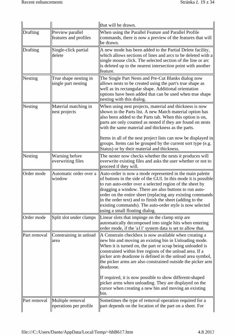
that will be drawn.Drafting Preview parallel
features and profilesWhen using the Parallel Feature and Parallel Profilecommands, there is now a preview of the features that willbe drawn.
Drafting Single-click partialdelete
A new mode has been added to the Partial Delete facility,which allows sections of lines and arcs to be deleted with asingle mouse click. The selected section of the line or arcis deleted up to the nearest intersection point with anotherfeature.
Nesting True shape nesting insingle part nesting
The Single Part Nests and Pre-Cut Blanks dialog nowallows nests to be created using the part's true shape aswell as its rectangular shape. Additional orientationoptions have been added that can be used when true shapenesting with this dialog.
Nesting Material matching innest projects
When using nest projects, material and thickness is nowshown in the Parts list. A new Match material option hasalso been added to the Parts tab. When this option is on,parts are only counted as nested if they are found on nestswith the same material and thickness as the parts.
Items in all of the nest project lists can now be displayed ingroups. Items can be grouped by the current sort type (e.g.Status) or by their material and thickness.
Nesting Warning beforeoverwriting files
The nester now checks whether the nests it produces willoverwrite existing files and asks the user whether or not toproceed if they will.
Order mode Automatic order over awindow
Auto-order is now a mode represented in the main paletteof buttons in the side of the GUI. In this mode it is possibleto run auto-order over a selected region of the sheet bydragging a window. There are also buttons to run auto-order on the entire sheet (replacing any existing commandsin the order text) and to finish the sheet (adding to theexisting commands). The auto-order style is now selectedusing a small floating dialog.
Order mode Split slot under clamps Linear slots that impinge on the clamp strip areautomatically decomposed into single hits when enteringorder mode, if the 'a11' system data is set to allow that.
Part removal Constraining in unloadarea
A Constrain checkbox is now available when creating anew bin and moving an existing bin in Unloading mode.When it is turned on, the part or scrap being unloaded isconstrained within free regions of the unload area. If apicker arm deadzone is defined in the unload area symbol,the picker arms are also constrained outside the picker armdeadzone.
If required, it is now possible to show different-shapedpicker arms when unloading. They are displayed on thecursor when creating a new bin and moving an existingbin.
Part removal Multiple removaloperations per profile
Sometimes the type of removal operation required for apart depends on the location of the part on a sheet. For
Stránka . 19 z 34Recent enhancements
4.8.2013file:///C:/Users/Dante/AppData/Local/Temp/~hhB617.htm

Issue 27.3.01
example, a part picker may not be able to remove parts tooclose to the clamps. It is now possible to allow for suchsituations by specifying several removal operations foreach profile, with a prioritized order.
Verifier Indexable multi-toolsupport
Verifiers now correctly handle dynamic indexable multi-tools, and show the same best-case / worst-case variationsof the working range and clamp deadzones as are shown inorder mode for such tools.
Licensing Configuration dialogfor network licensing
The CLS icon in the Windows taskbar now has an optionto show a dialog for selecting the licence server. Thedialog allows the user to search for a network licenceserver and connect to it. The dialog will then show thelicences that are available from the server.
Area Title Details3D 3D design defaults and
material aliasesDefaults for the bend radius, bend relief, hem radius andclearance can now be specified in the bend parameter file(bend_param.xml). The default properties for a new partare now obtained from the bend parameter file, ifavailable. These include the bend allowance.
The bend allowance overrides in the Bend Options andHem Options dialogs are now initialised from the bendparameter file, if available.
The bend parameter file has also been enhanced to allowfor material name aliasing. This allows different materialnames to share the same settings.
3D Transfer forms toRadbendCNC
A new version of the SMX file format has beenintroduced. SMX version 2.01 supports form features.
Form features may now be transferred from Radan 3D toRadbendCNC.
3D Associate bends withsheets in SMX import
In a model imported from SMX, the bends are nowassociated with the sheets. This means that a bend radiusmay be edited without leaving gaps between the bend andits adjoining sheets.
3D Geometry Utilitiesdialog in 3D ProfileEditing
The Geometry Utilities dialog can now be invoked fromthe Check View dialog in 3D Profile Editing. This allowsgeometry healing to be performed on profiles.
3D Importing Inventor2010 models
Radan 3D now supports import of Inventor 2010 files,provided you have the full Inventor 2010 product installed,or have downloaded and installed the Inventor View 2010product.
3D Importing SolidWorks2009 models
Radan 3D now supports import of SolidWorks 2009 files.
3D Optional thickness When importing models into 3D, the calculation of the
Stránka . 20 z 34Recent enhancements
4.8.2013file:///C:/Users/Dante/AppData/Local/Temp/~hhB617.htm
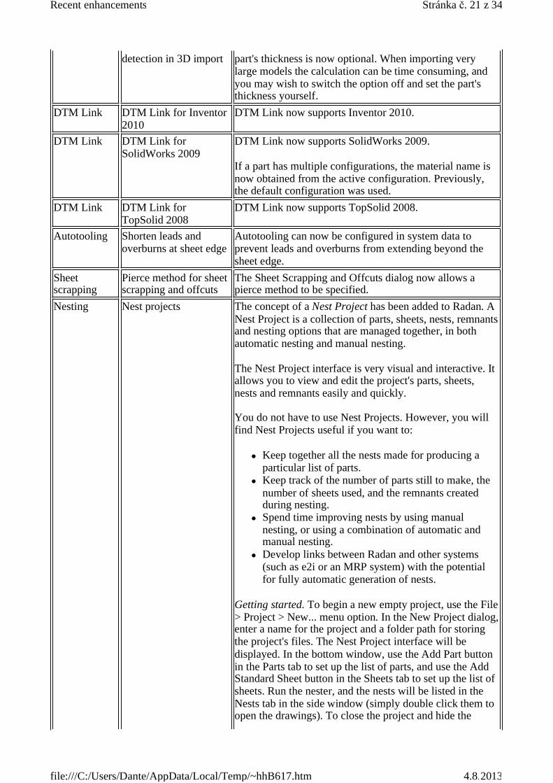
detection in 3D import part's thickness is now optional. When importing verylarge models the calculation can be time consuming, andyou may wish to switch the option off and set the part'sthickness yourself.
DTM Link DTM Link for Inventor2010
DTM Link now supports Inventor 2010.
DTM Link DTM Link forSolidWorks 2009
DTM Link now supports SolidWorks 2009.
If a part has multiple configurations, the material name isnow obtained from the active configuration. Previously,the default configuration was used.
DTM Link DTM Link forTopSolid 2008
DTM Link now supports TopSolid 2008.
Autotooling Shorten leads andoverburns at sheet edge
Autotooling can now be configured in system data toprevent leads and overburns from extending beyond thesheet edge.
Sheetscrapping
Pierce method for sheetscrapping and offcuts
The Sheet Scrapping and Offcuts dialog now allows apierce method to be specified.
Nesting Nest projects The concept of a Nest Project has been added to Radan. ANest Project is a collection of parts, sheets, nests, remnantsand nesting options that are managed together, in bothautomatic nesting and manual nesting.
The Nest Project interface is very visual and interactive. Itallows you to view and edit the project's parts, sheets,nests and remnants easily and quickly.
You do not have to use Nest Projects. However, you willfind Nest Projects useful if you want to:
Keep together all the nests made for producing aparticular list of parts.Keep track of the number of parts still to make, thenumber of sheets used, and the remnants createdduring nesting.Spend time improving nests by using manualnesting, or using a combination of automatic andmanual nesting.Develop links between Radan and other systems(such as e2i or an MRP system) with the potentialfor fully automatic generation of nests.
Getting started. To begin a new empty project, use the File> Project > New... menu option. In the New Project dialog,enter a name for the project and a folder path for storingthe project's files. The Nest Project interface will bedisplayed. In the bottom window, use the Add Part buttonin the Parts tab to set up the list of parts, and use the AddStandard Sheet button in the Sheets tab to set up the list ofsheets. Run the nester, and the nests will be listed in theNests tab in the side window (simply double click them toopen the drawings). To close the project and hide the
Stránka . 21 z 34Recent enhancements
4.8.2013file:///C:/Users/Dante/AppData/Local/Temp/~hhB617.htm

interface, use the File > Project > Close menu option. Youwill be prompted to save any changes you have made tothe project.
If you do not have a Nest Project open, the nestinginterface is the same as in previous versions.
Nesting Allow more than 100sheet sizes
When nesting with multiple sheet sizes, an unlimitednumber of different sheet sizes may be used.
Manualnesting
Easier control overautomation options inFinish Nesting
The Finalise Nest tab of the Finish Manual Nesting dialognow has a checkbox to control whether the various optionsin the Automation tab are applied.
Order mode Order mode assist areas The concept of assist areas has been introduced in Ordermode. The outlines of the areas are drawn in the Ordermode graphics to assist with the ordering process.
For example, on a combination machine, it may be usefulto visualise the punching area when a laser tool is active(and vice versa). An Order mode assist area is suitable forthis purpose.
An Order mode assist area may also be useful forvisualisation of areas to avoid.
The assist areas must be configured in system data.Order mode Indexable multi-tools Support for indexable multi-tools has been improved.
Order mode now shows the areas that may or may not bereachable depending on whether the active tool can berotated appropriately. It also calculates whether featuresare actually reachable by some possible rotation of thetool.
Configuration Standard Sheet Editor Standard sheets information is now stored in a singlestandard sheets file which is common to all machine tools.The file may contain machine-specific information, forexample if certain materials or sheet sizes can be used by aparticular machine. This replaces the former system ofhaving separate standard sheets files for differentmachines.
The new standard sheets file allows a manufacturingdatabase (MDB) folder name to be specified for eachmaterial. This is a machine-specific setting. It allows thesame material name to be used with different machinetools, even if the machines use different folders in theMDB (i.e., if their autotooling or block compiler settingsare different).
The Standard Sheet Editor dialog has been enhanced forediting the new standard sheets file. The information isdisplayed as a tree view. Items in the tree view that are inuse by the current machine tool are displayed in bold type.
Radview Upgrade Apache andPerl
Updated the versions of various software packages used inthe Radview products, notably to Apache 2.2.10 and Perl
Stránka . 22 z 34Recent enhancements
4.8.2013file:///C:/Users/Dante/AppData/Local/Temp/~hhB617.htm
Issue 27.1.01
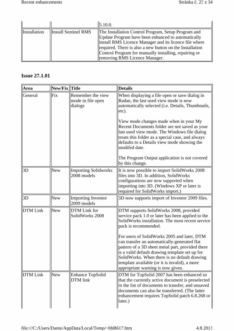
5.10.0.Installation Install Sentinel RMS The Installation Control Program, Setup Program and
Update Program have been enhanced to automaticallyinstall RMS Licence Manager and its licence file whererequired. There is also a new button on the InstallationControl Program for manually installing, repairing orremoving RMS Licence Manager.
Area New/Fix Title DetailsGeneral Fix Remember the view
mode in file opendialogs
When displaying a file open or save dialog inRadan, the last used view mode is nowautomatically selected (i.e. Details, Thumbnails,etc).
View mode changes made when in your MyRecent Documents folder are not saved as yourlast used view mode. The Windows file dialogtreats this folder as a special case, and alwaysdefaults to a Details view mode showing themodifed date.
The Program Output application is not coveredby this change.
3D New Importing Solidworks2008 models
It is now possible to import SolidWorks 2008files into 3D. In addition, SolidWorksconfigurations are now supported whenimporting into 3D. (Windows XP or later isrequired for SolidWorks import.)
3D New Importing Inventor2009 models
3D now supports import of Inventor 2009 files.
DTM Link New DTM Link forSolidWorks 2008
DTM supports SolidWorks 2008, providedservice pack 1.0 or later has been applied to theSolidWorks installation. The most recent servicepack is recommended.
For users of SolidWorks 2005 and later, DTMcan transfer an automatically-generated flatpattern of a 3D sheet metal part, provided thereis a valid default drawing template set up forSolidWorks. When there is no default drawingtemplate available (or it is invalid), a moreappropriate warning is now given.
DTM Link New Enhance TopSolidDTM link
DTM for TopSolid 2007 has been enhanced sothat the currently active document is preselectedin the list of documents to transfer, and unsaveddocuments can also be transferred. (The latterenhancement requires TopSolid patch 6.8.268 orlater.)
Stránka . 23 z 34Recent enhancements
4.8.2013file:///C:/Users/Dante/AppData/Local/Temp/~hhB617.htm
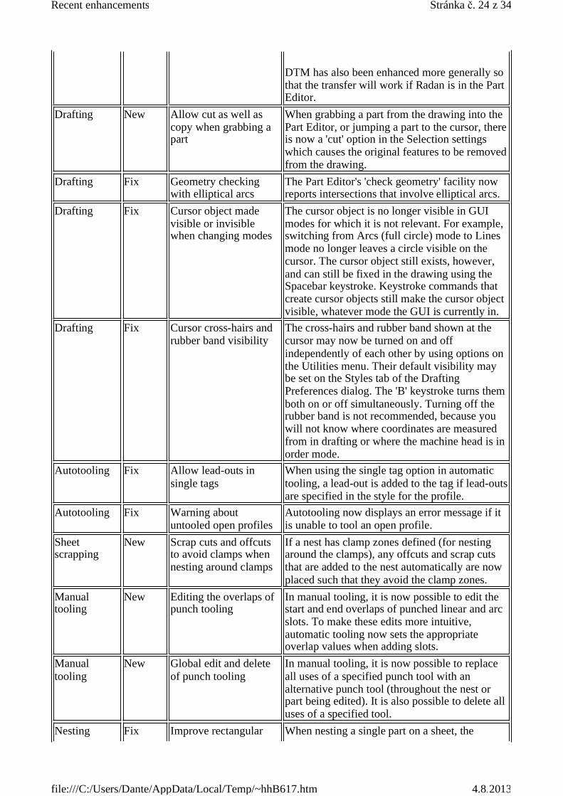
DTM has also been enhanced more generally sothat the transfer will work if Radan is in the PartEditor.
Drafting New Allow cut as well ascopy when grabbing apart
When grabbing a part from the drawing into thePart Editor, or jumping a part to the cursor, thereis now a 'cut' option in the Selection settingswhich causes the original features to be removedfrom the drawing.
Drafting Fix Geometry checkingwith elliptical arcs
The Part Editor's 'check geometry' facility nowreports intersections that involve elliptical arcs.
Drafting Fix Cursor object madevisible or invisiblewhen changing modes
The cursor object is no longer visible in GUImodes for which it is not relevant. For example,switching from Arcs (full circle) mode to Linesmode no longer leaves a circle visible on thecursor. The cursor object still exists, however,and can still be fixed in the drawing using theSpacebar keystroke. Keystroke commands thatcreate cursor objects still make the cursor objectvisible, whatever mode the GUI is currently in.
Drafting Fix Cursor cross-hairs andrubber band visibility
The cross-hairs and rubber band shown at thecursor may now be turned on and offindependently of each other by using options onthe Utilities menu. Their default visibility maybe set on the Styles tab of the DraftingPreferences dialog. The 'B' keystroke turns themboth on or off simultaneously. Turning off therubber band is not recommended, because youwill not know where coordinates are measuredfrom in drafting or where the machine head is inorder mode.
Autotooling Fix Allow lead-outs insingle tags
When using the single tag option in automatictooling, a lead-out is added to the tag if lead-outsare specified in the style for the profile.
Autotooling Fix Warning aboutuntooled open profiles
Autotooling now displays an error message if itis unable to tool an open profile.
Sheetscrapping
New Scrap cuts and offcutsto avoid clamps whennesting around clamps
If a nest has clamp zones defined (for nestingaround the clamps), any offcuts and scrap cutsthat are added to the nest automatically are nowplaced such that they avoid the clamp zones.
Manualtooling
New Editing the overlaps ofpunch tooling
In manual tooling, it is now possible to edit thestart and end overlaps of punched linear and arcslots. To make these edits more intuitive,automatic tooling now sets the appropriateoverlap values when adding slots.
Manualtooling
New Global edit and deleteof punch tooling
In manual tooling, it is now possible to replaceall uses of a specified punch tool with analternative punch tool (throughout the nest orpart being edited). It is also possible to delete alluses of a specified tool.
Nesting Fix Improve rectangular When nesting a single part on a sheet, the
Stránka . 24 z 34Recent enhancements
4.8.2013file:///C:/Users/Dante/AppData/Local/Temp/~hhB617.htm
nesting rectangular nester sometimes only nested thepart at 0 or 90 degrees when it could have nestedthe part at both 0 and 90 degrees to fit moreparts on the sheet. Also, Single Part Nestingcould sometimes fit more parts on a sheet thanthe rectangular nester, even when the rectangularnester nested the part at both 0 and 90 degrees.
These problems have now been fixed. Therectangular nester should now be able to nest atleast as many parts on a sheet as Single PartNesting, and sometimes more. Also, as a resultof this fix, the utilisation of rectangular nestscontaining a number of different parts willsometimes be improved.
The rectangular nester has also been enhancedso that it now tries to maximise the usefulleftover sheet area as well as the number of partson the sheet.
Nesting Fix More robust handlingof geometry
Some of the basic geometry code in the Radansoftware has been made more robust. Thisaddresses a number of different problems,including (1) failure of cursor constraint inmanual nesting, particularly when tooling isincluded in the shapes of the parts, (2) failure touse certain parts in automatic nesting whenincluding tooling in the parts' shapes, (3) failureto calculate remnants correctly in automaticnesting, and (4) the whole sheet being shown onthe cursor when using the unloading facility.
Nesting New Add run time andremnant details to nestannotation
Annotation added to nest drawings now includesthe run time, the source sheet drawing and thenumber of remnants generated as appropriate.The run time will be added by the automaticnester if the auto-compile option is turned on. Ifthe block compiler or verifier is run after thenester, the run time will be added if you updatethe annotation using the Finish Manual Nestingdialog.
Nesting Fix Single Part Nestingprompts before deletingdrawing
The Single Part Nests and Pre-Cut Blanks dialognow has Cancel and OK buttons. Cancel restoresthe nest that was on the screen before the dialogwas opened.
Nesting New More control over nestdrawing names
The interpretation of the Nest name field in theNest Schedule Editor dialog has been enhancedto allow users to specify their own namingconventions for nest drawings, notably to allowthe 'job name' to be followed by the nest numberso that all the nests for a given job are listedtogether in Windows Explorer. The nest numbermay also be padded with leading zeros so that 10doesn't get listed between 1 and 2.
Stránka . 25 z 34Recent enhancements
4.8.2013file:///C:/Users/Dante/AppData/Local/Temp/~hhB617.htm
This is achieved by allowing a string of ?characters in the Nest name. If such a string ispresent then the nest name is made by simplyreplacing the string of ?s with the nest number,padded with the required number of leadingzeros. If there are no ? characters present thenthe old naming convention is still used.
Order mode New Part-by-part ordering ofcommon-cut parts inwindow Profilecommand
The window Profile command has beenenhanced to allow a part-by-part cutting order ofparts that have common-line cutting betweenthem. Normally, all internal profiles in a groupof common-cut parts are ordered before any ofthe common-cut external profiles, to ensure thatan external profile of a part is never cut beforean internal profile. When part-by-part ordering isused, however, all the profiles of a part arecompleted before moving on to the next part.This implies that some parts will have somesections of their external profiles cut before theirinternal profiles, as a side-effect of cuttingneighbouring parts. Part-by-part ordering mayimprove the quality of the parts produced byreducing the effect of heat expansion across thesheet. The option is controlled by ao4-b in themachine system data.
Order mode New Control ordering ofscrap cuts and offcutsin window Profilecommand
For profiling machines, it is now possible to cutparts, offcuts and scrap cuts separately in ordermode, even when they all use the same cuttingcondition, by using separate window Profilecommands in the order text. The window Profilecommand may optionally be followed by thefollowing keywords:
'Offcuts' means do the offcut tooling features,'Scrap-cuts' means do the scrap cut toolingfeatures,'Offcuts Scrap-cuts' means do the offcut andscrap cut tooling features together,'No-offcuts' means do all tooling features exceptthe offcuts,'No-scrap-cuts' means do all tooling featuresexcept the scrap cuts,'No-offcuts No-scrap-cuts' means do all toolingfeatures that are neither offcuts nor scrap cuts.
For example, 'Profile [-42.8 1026.7 1642.5 -39.3] Scrap-cuts'.
For auto-order, the same keywords may be usedin Profile commands in the auto-order text.
Order mode Fix Unloading with morethan 20 groups
The unload facility now allows up to 40 groupsin the order text to contain Pick commands.
Stránka . 26 z 34Recent enhancements
4.8.2013file:///C:/Users/Dante/AppData/Local/Temp/~hhB617.htm
Issue 26.3.01
containing PicksDNC Fix Program Output
window resizableThe Program Output window may be resized.
Configuration New Redesigned MachineConfiguration Editordialog
The Machine Configuration Editor dialog is nowbased on a tree view instead of tabbed pages.Controls have been added for more system dataitems than before, such as defining times usedby the Verifier. A default tool may now bespecified for single and step-and-repeat punchblows.
Configuration Fix Changing theconfiguration datafolder under WindowsVista
The Configuration Folder option on the File |Administrative Tools menu now allows the pathof the configuration data folder to be changedunder Windows Vista. The dialog has also beenenhanced to allow certain other folder paths tobe changed.
COMInterface
New Add COM methods fornew/open/save/closedrawings and symbols
Methods and properties have been added to theApplication object in the Radan COM API forstarting a new drawing or symbol and foropening and saving drawings and symbols.
COMInterface
New Add COM methods foraccessing system data
Methods and properties have been added to theApplication object in the Radan COM API foraccessing system data files.
Area New/Fix Title DetailsGeneral New GUI style
modernisationThe appearance of the GUI has been modernisedby the introduction of a graduated colourbackground for toolbars and palettes, a flat lookfor buttons, and a more up to date style fordropdown lists, checkboxes, and so on.
The Windows colour scheme (which you can setusing Display Properties in Control Panel) istaken into account. In Windows XP, theavailable colours are blue (the default), olivegreen and silver.
General New Change the cursor andthe default colours
By default, the cursor crosshairs are now turnedoff. The rubber band remains visible as a dottedline.
The default background colour of the graphicsarea has been changed from black to white in 2Dand from black to blue in 3D. The defaultcolours of several of the drawing pens have alsobeen changed, as have the default colours ofdrafting aids (such as Smart Select highlighting)and of graphics that appear in Order Mode andthe Verifier. The new colours are designed for
Stránka . 27 z 34Recent enhancements
4.8.2013file:///C:/Users/Dante/AppData/Local/Temp/~hhB617.htm
use with the white background.
These changes have been made to make Radanmore consistent with other graphics applicationsand to improve the clarity and usability of thegraphics.
The default pen for colour filled parts (pen 10) isnow light grey (instead of dark red). If you wantto use a different pen, you may do so in the Tooland Pen Preferences tab of the MachineConfiguration Editor.
The concept of a 'graphics theme' has beenintroduced to make it easy to switch to astandard set of colours. This is controlled from aThemes tab in the Colour Preferences dialog (onthe Edit menu in 2D). The main graphics themesare the Standard theme (the new default colours)and the Classic theme (the old default colours).If you customised some of your colours beforeyou upgraded to this issue, you will also have aPreserved theme available which will restoreyour old colours. This allows you to try out theStandard theme colours, safe in the knowledgethat you can get your old colours back again ifyou prefer them.
Colours used for geometry checking in the PartEditor and several colours used in Order Modeand the Verifier may now be chosen in theColour Preferences dialog.
DXF andDWG
New Improve colour to penconversion
In the Colour Mapping tab of the 2D ImportOptions dialog, the default mapping from DXFcolours to pens has been changed. Instead ofsimply mapping each DXF colour number to thesame pen number, the default mapping nowpreserves the colours of the original drawing asmuch as possible. For example, DXF colour 1(which is red) is converted to pen 2 by default. Itis still possible to set up your own customisedmapping from DXF colours to pens.
DTM Link New Enhance Inventor DTMLink
The DTM Link now supports Inventor 2009.
Sheetscrapping
Fix Avoid piercing nearparts
Sheet scrapping cuts that are placed between twoparts are now always cut from the centreregardless of the 'cut from centre' setting in thedialog. The 'cut from centre' setting now onlyaffects cuts that are between a part and the edgeof the sheet.
Manualnesting
New Save remnants from theFinish Manual Nestingdialog
The Finish Manual Nesting dialog may now beused to save remnant drawings for the currentnest. The options available for saving remnants
Stránka . 28 z 34Recent enhancements
4.8.2013file:///C:/Users/Dante/AppData/Local/Temp/~hhB617.htm
Issue 26.1.01
in manual nesting are the same as those in theparts nester. Any existing remnant drawings forthe nest are replaced when new ones are saved(provided the name of the nest drawing has notbeen changed).
A 'Remnants saved' drawing attribute is nowdefined for nest drawings, the value of which isthe number of remnant drawings saved for thenest.
The 'Used remnant' attribute has been renamedthe 'Remnant source' attribute. In a remnantdrawing, it is set to the name of the nest fromwhich the remnant was produced. In a nestdrawing based on a remnant, it is set to the nameof the remnant that was used.
The Finish Manual Nesting dialog now updatesleftover space information in the nest drawing (ifthe 'minimum area worth saving in add-nesting'system data is non-zero). This allows theautomatic nester to add more parts to a nest thathas been edited manually.
Order mode Fix Improve hazardavoidance for machineswith offset tools
Hazard avoidance has been improved when it isused for machines with offset tools. Whencalculating what avoidance moves are necessarybetween two positions (e.g. punch blows), ifthere is a tool change between the two positions,calculate the entire route based on the currenttool (at the start of the move), and where thecurrent tool will be when the new tool is at thedesired position. This will result in somechanges to the avoidance route, but the newroute will reflect the correct moves for themachine.
Area New/Fix Title DetailsGeneral New Windows Vista support The Radan software is now compatible with the
Windows Vista operating system.
All Radan programs are classified as StandardUser Applications with respect to the UserAccount Control regime on Windows Vista(except for the installer which is anAdministrator Application). As a consequence ofthis, the Change Configuration Folder menuitem is disabled under Windows Vista. Aseparate program for performing that and otheradministrative tasks will be introduced in a
Stránka . 29 z 34Recent enhancements
4.8.2013file:///C:/Users/Dante/AppData/Local/Temp/~hhB617.htm
future issue.General New Technology upgrade The Radan software is now developed using an
improved C++ compiler. This has severalbenefits, of which the most noticeable for endusers is a general improvement in the speed atwhich the Radan software runs.
The Radan software has also been changed totake advantage of upgraded versions of severalthird-party software components:- Rainbow dongle driver- Apache web server (in Radview)- libpng and zlib- Cadology DToolsX- Parasolid Kernel (from version 17 to version19)- Solid Edge Part Reader (from 18 to 20)- Dimensional Constraint Manager (DCM) fromD-Cubed (to v49.0)- Hidden Line Manager (HLM) from D-Cubed(to v37)- Spatial ACIS modeller (to 17)
3D New ACIS 17 upgrade The version of the Spatial ACIS modeller usedby Radan 3D has been upgraded to R17 SP2.The Pro/E, Parasolid, CATIA V4, CATIA V5and SolidWorks translators have been upgradedto the latest versions available.
The following file import enhancements havebeen made:- Support for SAT versions 16 and 17- Support for Pro/E Wildfire 3- Support for Parasolid V18 and V19- Support for Inventor 2008- Support for CATIA V5 R17- Support for SolidWorks 2007- Support for Solid Edge V20- Support for Unigraphics NX5
3D New Standard Open Filebrowser for 3D import
3D imports now share a common Open Filebrowser, showing the available formats in theFile Type dropdown list.
3D New Joggle bends and hemsin SMX output
SMX export will now support models thatcontain two connected bends (also known as ajoggle or S-bend), or a free bend (a bend that hasnothing attached on one side of it). This allowstransfer of such models into RadbendCNC.
3D New Support import ofUnigraphics part files
It is now possible to import Unigraphics partfiles into 3D. This is a licensed option.
3D New Automatic thicknessdetection for 3D fileimport
When importing a sheet metal model into 3D,the sheet thickness is calculated automaticallyand set in the part properties.
DTM Link New Enhance Inventor DTM The DTM Link now extracts document revision
Stránka . 30 z 34Recent enhancements
4.8.2013file:///C:/Users/Dante/AppData/Local/Temp/~hhB617.htm
Link information from Inventor. On direct transfer orfile recall, this information is stored in attribute114 (Revision number). Note that attribute 114is switched off by default, so you will need toswitch it on for drawings and symbols in orderto use this feature.
DTM Link New Enhance TopSolidDTM Link
The DTM Link now supports TopSolid v6.8.The DTM link for TopSolid now allows thetransfer of material, density and (for sheet metalparts only) thickness for 3D data.
Attributes New Attributes for thegeometric properties ofparts
A weight attribute and a set of geometryproperty attributes have been introduced forparts.
Drafting New Improvements to theCurved Rectangles andObrounds dialog
The functionality offered by the CurvedRectangles and Obrounds dialog has beenextended.
Drafting New Draw a trapeziumwithout using angle ofinclination
The user can now draw a trapezium byspecifying the top length instead of the angle ofinclination of the sides.
Drafting New Drawing normal linesto lines and arcs
The fixed length normal command in 2Ddrafting has been enhanced to allow the normalto be drawn from a selected latch point on theselected line or arc. Formerly, the normal wassimply drawn from the point on the selected lineor arc that was closest to the cursor.
Drafting New Construct shapes as truecursor objects
In the circle, ellipse, rectangle and other shapeconstruction modes that only require you toselect the shape's position, the preview shown onthe cursor is now a true cursor object. Thisallows you to put shapes down as step andrepeats by switching into cursor objects mode.
You can also rotate shapes on the cursor (as wellas general window-jumped geometry) by usingthe Page Up, Page Down, Left Arrow and RightArrow keys, and move the anchor point usingthe Tab and Shift+Tab keys. Formerly this wasonly possible with symbols.
DXF andDWG
New Support AutoCADversion 2007/2008DXF and DWG files
As well as allowing import of these formats, thesoftware now attempts recovery of corruptedfiles.
DXF andDWG
New More DXF importoptions
A 'Convert lines and arcs only' checkbox hasbeen added to the Conversion tab of the 2DImport Options dialog for DXF and DWG files.When switched on, only lines and arcs areimported.
A new 'Colour mapping' tab has been added tothe same dialog to allow DXF colours to bemapped into Radan pens by a user-definedmapping. Also, you can specify that only entities
Stránka . 31 z 34Recent enhancements
4.8.2013file:///C:/Users/Dante/AppData/Local/Temp/~hhB617.htm

in given colours will be imported.eQuote New Enhance eQuote to use
e2iIf you use eQuote in Radan for a given part, andyou use e2i, the 'Symbol Path' field in the e2iPart window will be populated automatically
Autotooling New Add 'pierce methods' toautotooling and supportadditional pierce typesdefined by the blockcompiler
Autotooling has been enhanced to support anynumber of pierce types defined by a blockcompiler. A new collection of settings known asa pierce method has been introduced. It containsa setting for pierce type, pierce diameter, andpre-pierce cutting condition, if pre-piercing issupported by your machine tool. A differentpierce method can then be assigned to each lead-in style, introducing more flexibility into theway parts are cut.
Sheetscrapping
New Enhance the SheetCutting dialog and addsimilar controls to theNest Schedule Editor
The Sheet Cutting dialog has been renamed theSheet Scrapping and Offcuts dialog and has beenredesigned. There are now more controlsavailable over scrap cuts, similar to thoseintroduced in Radan 07 for offcuts. The dialogalso has controls showing the material propertiesof a nest: in conjunction with the Settings menuthis makes it easy to configure and save settingsin the manufacturing database.
The Automation tab of the Nest Schedule Editornow has a 'Sheet scrapping and offcuts'checkbox. When this is turned on, scrap cuts oroffcuts (or both) will be added automatically toeach nest that the nester creates.
Manualtooling
New Allow number off andpitch to be specifiedsimultaneously forlinear and arc step andrepeats of punch blows
The 'Linear Step and Repeats' and 'Arc Step andRepeats' options in manual tooling mode nowallow both a number off and incrementaldistance to be specified at the same time.
Nesting New Remnant attribute setduring nesting
When a nest is created on a remnant, the nameof the remnant file that was used is nowrecorded in a drawing attribute (number 161), inthe nest results file, and in the HTML setupsheet.
Nesting New X axis multi-nozzlenesting
The nester now supports nesting for multi-nozzlemachines along the X axis (horizontal) directionas well as the Y axis (vertical) direction.
Nesting andautotooling
New Picking clusters innesting and autotooling
For machines with part pickers, the nester hasbeen enhanced to nest selected parts in 'pickingclusters'. For parts that are too small for thepicker's suckers to attach to, the parts can betagged into clusters in the nest so that eachcluster can be removed from the sheet as agroup.
A new tagging option has been added toautotooling so that, when tooling a nest, tags are
Stránka . 32 z 34Recent enhancements
4.8.2013file:///C:/Users/Dante/AppData/Local/Temp/~hhB617.htm
applied only for parts that are in picking clusters.Manualnesting
New Automation options inthe Finish ManualNesting dialog
Automation options are now available in theFinish Manual Nesting dialog, like those on theAutomation tab of the Nest Schedule Editor.This makes it easier than before to runautotooling, auto-order and the block compilerafter making manual edits to a nest, and aftercreating a nest using the single part nestingfacility.
Manualnesting
New Manipulate cursorobjects usingkeystrokes
In manual nesting, when you have a window-jumped group of parts on the cursor, the PageUp, Page Down, Left Arrow and Right Arrowkeys can now be used to rotate the group, andthe Tab and Shift+Tab keys can be used to movethe anchor point around the group. Formerly thiswas only possible with a single part on thecursor.
Manualnesting
New Don't display symboldimensions in NestModify mode
Dimensions in part symbols are no longer shownwhen manual nesting.
Order mode New Speed up windowProfile and Subroutinecommands for jobs withmany profiles
Speed improvements have been made to Ordermode for certain profile jobs. In particular,
1. The window Profile command has been madequicker for:
a. Jobs that have many profiles that do not havelead-ins (e.g. etched profiles)b. Jobs that have many profiles on machines thatcan pre-pierce (i.e. m181 set to 'y')c. Jobs that have many profiles on machines thatrequire pre-punching (i.e. ao2 set to 'y')d. Jobs that have many profiles in general
2. The window Subroutine command has beenmade quicker for:
a. Jobs cut using subroutines that have manyparts and many features in the whole jobb. Jobs cut using subroutines that have few parts,each with many features
As a consequence of some of these changes,block compiling will also be quicker for jobsthat contain many profiles on machines that usepre-piercing or pre-punching. Compiling forsome machines may also be quicker for jobs thatuse subroutines.
Order mode New When the compiler runsauto-order keep theresulting order text
If you run the block compiler when there are nocutting commands in the order text, auto-order isrun automatically. The lines added to the ordertext in these circumstances now remain after you
Stránka . 33 z 34Recent enhancements
4.8.2013file:///C:/Users/Dante/AppData/Local/Temp/~hhB617.htm
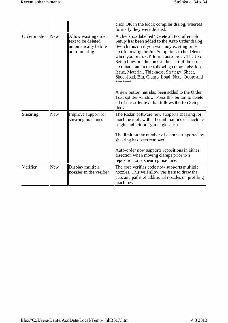
click OK in the block compiler dialog, whereasformerly they were deleted.
Order mode New Allow existing ordertext to be deletedautomatically beforeauto-ordering
A checkbox labelled 'Delete all text after JobSetup' has been added to the Auto Order dialog.Switch this on if you want any existing ordertext following the Job Setup lines to be deletedwhen you press OK to run auto-order. The JobSetup lines are the lines at the start of the ordertext that contain the following commands: Job,Issue, Material, Thickness, Strategy, Sheet,Sheet-load, Bin, Clamp, Load, Note, Quote and*******.
A new button has also been added to the OrderText splitter window. Press this button to deleteall of the order text that follows the Job Setuplines.
Shearing New Improve support forshearing machines
The Radan software now supports shearing formachine tools with all combinations of machineorigin and left or right angle shear.
The limit on the number of clamps supported byshearing has been removed.
Auto-order now supports repositions in eitherdirection when moving clamps prior to areposition on a shearing machine.
Verifier New Display multiplenozzles in the verifier
The core verifier code now supports multiplenozzles. This will allow verifiers to draw thecuts and paths of additional nozzles on profilingmachines.
Stránka . 34 z 34Recent enhancements
4.8.2013file:///C:/Users/Dante/AppData/Local/Temp/~hhB617.htm