radio receiving sets an/arn-123(v)1 (nsn 5826-01-016...
TRANSCRIPT

TM 11-5826-258-24
TECHNICAL MANUAL
ORGANIZATIONAL DIRECT SUPPORT, ANDGENERAL SUPPORT MAINTENANCE MANUAL
RADIO RECEIVING SETSAN/ARN-123(V)1
(NSN 5826-01-016-2762)AN/ARN-123(V)2
(NSN 5826-01-016-2761)
This copy IS a reprint which includes currentpages from Changes 1.
H E A D Q U A R T E R S , D E P A R T M E N T O F T H E A R M Y

TM 11-5826-258-24
TECHNICAL MANUAL HEADQUARTERSDEPARTMENT OF THE ARMY
No. 11-5826-258-24 WASHINGTON, DC, 12 August 1977
ORGANIZATIONAL, DIRECT SUPPORT, ANDGENERAL SUPPORT MAINTENANCE MANUAL
RADIO RECEIVING SETSAN/ARN-123(V)1 (NSN 5826-01-016-2762)AN/ARN-123(V)2 (NSN 5826-01-016-2761)AN/ARN-123(V)3 (NSN 5826-01-058-6800)
ANDAN/ARN-123(V)4 (NSN 5826-01-070-4067)
Current as of 24 August 1979
REPORTING ERRORS AND RECOMMENDING IMPROVEMENTSYou can help improve this manual. If you find any mistakes or if you know of a way to improve the
procedures, please let us know.Mail your letter, DA Form 2028 (Recommended Changes to Publications and Blank Forms), or DA Form
2028-2 located in back of this manual direct to: Commander, US Army Communications and ElectronicsMateriel Readiness Command, ATTN: DRSEL-ME-MQ, Fort Monmouth, NJ 07703.
In either case, a reply will be furnished direct to you.
ParagraphCHAPTER 1. INTRODUCTION
Section I. GeneralScope . . . . . . . . . . . . . . . . . . . . . . . . . . . . . . . . . . . . . . . . . . . . . . . . . . . . . . . . . . . . . . . . . . . . . . . . . . . . . . . . . . . .Indexes of publications. . . . . . . . . . . . . . . . . . . . . . . . . . . . . . . . . . . . . . . . . . . . . . . . . . . . . . . . . . . . . . . . . . .Forms and records. . . . . . . . . . . . . . . . . . . . . . . . . . . . . . . . . . . . . . . . . . . . . . . . . . . . . . . . . . . . . . . . . . . . . . Warranty . . . . . . . . . . . . . . . . . . . . . . . . . . . . . . . . . . . . . . . . . . . . . . . . . . . . . . . . . . . . . . . . . . . . . . . . . . . . . . . . . .Reporting equipment improvement recommendations (EIR) . . . . . . . . . . . . . . . . . . . . . . . . . . . . . . .Administrative storage . . . . . . . . . . . . . . . . . . . . . . . . . . . . . . . . . . . . . . . . . . . . . . . . . . . . . . . . . . . . . . . . . . .Destruction of Army electronics materiel . . . . . . . . . . . . . . . . . . . . . . . . . . . . . . . . . . . . . . . . . . . . . . . . .
II. Description and dataDescription of receiving set. . . . . . . . . . . . . . . . . . . . . . . . . . . . . . . . . . . . . . . . . . . . . . . . . . . . . . . . . . . . . . .Description of receiver . . . . . . . . . . . . . . . . . . . . . . . . . . . . . . . . . . . . . . . . . . . . . . . . . . . . . . . . . . . . . . . . . . . Description of receiver control . . . . . . . . . . . . . . . . . . . . . . . . . . . . . . . . . . . . . . . . . . . . . . . . . . . . . . . . . . . . Description of receiver mount . . . . . . . . . . . . . . . . . . . . . . . . . . . . . . . . . . . . . . . . . . . . . . . . . . . . . . . . . . . . System application. . . . . . . . . . . . . . . . . . . . . . . . . . . . . . . . . . . . . . . . . . . . . . . . . . . . . . . . . . . . . . . . . . . . . . . Tabulated data . . . . . . . . . . . . . . . . . . . . . . . . . . . . . . . . . . . . . . . . . . . . . . . . . . . . . . . . . . . . . . . . . . . . . . . . . .Items comprising an operable equipment . . . . . . . . . . . . . . . . . . . . . . . . . . . . . . . . . . . . . . . . . . . . . . . . . Additional equipment required . . . . . . . . . . . . . . . . . . . . . . . . . . . . . . . . . . . . . . . . . . . . . . . . . . . . . . . . . . .
III. Service upon receiptPackaging data . . . . . . . . . . . . . . . . . . . . . . . . . . . . . . . . . . . . . . . . . . . . . . . . . . . . . . . . . . . . . . . . . . . . . . . . . . Unpacking instructions . . . . . . . . . . . . . . . . . . . . . . . . . . . . . . . . . . . . . . . . . . . . . . . . . . . . . . . . . . . . . . . . . .Checking unpacked equipment . . . . . . . . . . . . . . . . . . . . . . . . . . . . . . . . . . . . . . . . . . . . . . . . . . . . . . . . . . . Repacking . . . . . . . . . . . . . . . . . . . . . . . . . . . . . . . . . . . . . . . . . . . . . . . . . . . . . . . . . . . . . . . . . . . . . . . . . . . . . . . Shipment marking . . . . . . . . . . . . . . . . . . . . . . . . . . . . . . . . . . . . . . . . . . . . . . . . . . . . . . . . . . . . . . . . . . . . . . .
CHAPTER 2. OPERATING INSTRUCTIONSSection I. Controls and instruments
Damage from improper settings. . . . . . . . . . . . . . . . . . . . . . . . . . . . . . . . . . . . . . . . . . . . . . . . . . . . . . . . . .Operator/crew controls . . . . . . . . . . . . . . . . . . . . . . . . . . . . . . . . . . . . . . . . . . . . . . . . . . . . . . . . . . . . . . . . . . .
II. Operation under usual conditionsTypes of operation . . . . . . . . . . . . . . . . . . . . . . . . . . . . . . . . . . . . . . . . . . . . . . . . . . . . . . . . . . . . . . . . . . . . . .Starting procedure . . . . . . . . . . . . . . . . . . . . . . . . . . . . . . . . . . . . . . . . . . . . . . . . . . . . . . . . . . . . . . . . . . . . . . .VOR operation . . . . . . . . . . . . . . . . . . . . . . . . . . . . . . . . . . . . . . . . . . . . . . . . . . . . . . . . . . . . . . . . . . . . . . . . . . .ILS operation . . . . . . . . . . . . . . . . . . . . . . . . . . . . . . . . . . . . . . . . . . . . . . . . . . . . . . . . . . . . . . . . . . . . . . . . . . .Stopping procedure . . . . . . . . . . . . . . . . . . . . . . . . . . . . . . . . . . . . . . . . . . . . . . . . . . . . . . . . . . . . . . . . . . . . . .
1-11-21-31-41-51-61-7
1-81-91-101-111-121-131-141-15
Page
1-11-11-11-11-11-31-3
1-31-31-41-41-41-41-71-8
1-81-91-91-91-9
2-12-1
2-12-12-12-42-5
1-161-171-181-191-20
2-12-2
2-32-42-52-62-7
Change 1 i

TM 11-5826-258-24Paragraph
III. Operation under unusual conditionsWarning flags . . . . . . . . . . . . . . . . . . . . . . . . . . . . . . . . . . . . . . . . . . . . . . . . . . . . . . . . . . . . . . . . . . . . . . . . . . . 2 - 8Extreme temperatures . . . . . . . . . . . . . . . . . . . . . . . . . . . . . . . . . . . . . . . . . . . . . . . . . . . . . . . . . . . . . . . . . . . . 2-9
IV. Preflight (daily) operational checkGeneral . . . . . . . . . . . . . . . . . . . . . . . . . . . . . . . . . . . . . . . . . . . . . . . . . . . . . . . . . . . . . . . . . . . . . . . . . . . . . . . . . 2-10Operational check/self-test . . . . . . . . . . . . . . . . . . . . . . . . . . . . . . . . . . . . . . . . . . . . . . . . . . . . . . . . . . . . . . .
CHAPTER 3. MAINTENANCE INSTRUCTIONSSection I. Repainting and refinishing
Original protective finish . . . . . . . . . . . . . . . . . . . . . . . . . . . . . . . . . . . . . . . . . . . . . . . . . . . . . . . . . . . . . . . . . 3-1Retouching/repainting . . . . . . . . . . . . . . . . . . . . . . . . . . . . . . . . . . . . . . . . . . . . . . . . . . . . . . . . . . . . . . . . . . .
II. Preventive maintenance checks and servicesGeneral . . . . . . . . . . . . . . . . . . . . . . . . . . . . . . . . . . . . . . . . . . . . . . . . . . . . . . . . . . . . . . . . . . . . . . . . . . . . . . . . . 3-3Flight line preventive maintenance . . . . . . . . . . . . . . . . . . . . . . . . . . . . . . . . . . . . . . . . . . . . . . . . . . . . . . . 3-4Bench test preventive maintenance . . . . . . . . . . . . . . . . . . . . . . . . . . . . . . . . . . . . . . . . . . . . . . . . . . . . . . . 3-5
III. TroubleshootingGeneral . . . . . . . . . . . . . . . . . . . . . . . . . . . . . . . . . . . . . . . . . . . . . . . . . . . . . . . . . . . . . . . . . . . . . . . . . . . . . . . . . 3-6Corrective action . . . . . . . . . . . . . . . . . . . . . . . . . . . . . . . . . . . . . . . . . . . . . . . . . . . . . . . . . . . . . . . . . . . . . . . .3 - 7
IV. MaintenanceGeneral . . . . . . . . . . . . . . . . . . . . . . . . . . . . . . . . . . . . . . . . . . . . . . . . . . . . . . . . . . . . . . . . . . . . . . . . . . . . . . . . . . 3-8Cleaning . . . . . . . . . . . . . . . . . . . . . . . . . . . . . . . . . . . . . . . . . . . . . . . . . . . . . . . . . . . . . . . . . . . . . . . . . . . . . . . . 3-9Removal and replacement of receiver . . . . . . . . . . . . . . . . . . . . . . . . . . . . . . . . . . . . . . . . . . . . . . . . . . . . . . . 3-10Removal and replacement of mount . . . . . . . . . . . . . . . . . . . . . . . . . . . . . . . . . . . . . . . . . . . . . . . . . . . . . . . 3-11Removal and replacement of Control C-1004/ARN-123(V) or C10049/ARN-123(v) . . . . . . . . . . . 3-12Control parts replacement . . . . . . . . . . . . . . . . . . . . . . . . . . . . . . . . . . . . . . . . . . . . . . . . . . . . . . . . . . . . . . 3-l3
V. Flight line testsGeneral . . . . . . . . . . . . . . . . . . . . . . . . . . . . . . . . . . . . . . . . . . . . . . . . . . . . . . . . . . . . . . . . . . . . . . . . . . . . . . . . . . . . . . . . 3-l4Flight line operational tests . . . . . . . . . . . . . . . . . . . . . . . . . . . . . . . . . . . . . . . . . . . . . . . . . . . . . . . . . . . . . .3-15
VI. Direct and general support bench testsGeneral . . . . . . . . . . . . . . . . . . . . . . . . . . . . . . . . . . . . . . . . . . . . . . . . . . . . . . . . . . . . . . . . . . . . . . . . . . . . . . . . .3 - 1 6Test equipment calibration . . . . . . . . . . . . . . . . . . . . . . . . . . . . . . . . . . . . . . . . . . . . . . . . . . . . . . . . . . . . . . ..... 3-l7Receiver control tests . . . . . . . . . . . . . . . . . . . . . . . . . . . . . . . . . . . . . . . . . . . . . . . . . . . . . . . . . . . . . . . . . . . . 3-l8VOR bench tests . . . . . . . . . . . . . . . . . . . . . . . . . . . . . . . . . . . . . . . . . . . . . . . . . . . . . . . . . . . . . . . . . . . . . . . . 3-19LOC bench tests . . . . . . . . . . . . . . . . . . . . . . . . . . . . . . . . . . . . . . . . . . . . . . . . . . . . . . . . . . . . . . . . . . . . . . . . . . . 3-20Glideslope bench tests . . . . . . . . . . . . . . . . . . . . . . . . . . . . . . . . . . . . . . . . . . . . . . . . . . . . . . . . . . . . . . . . . . . . . 3-2lMarker beacon bench tests . . . . . . . . . . . . . . . . . . . . . . . . . . . . . . . . . . . . . . . . . . . . . . . . . . . . . . . . . . 3-22
VII. Alternate VOR/LOC bench testsGeneral . . . . . . . . . . . . . . . . . . . . . . . . . . . . . . . . . . . . . . . . . . . . . . . . . . . . . . . . . . . . . . . . . . . . . . . . . . . . . . . . . 3-23VOR bench tests . . . . . . . . . . . . . . . . . . . . . . . . . . . . . . . . . . . . . . . . . . . . . . . . . . . . . . . . . . . . . . . . . . . . . . . . .. . 3-24LOC bench tests . . . . . . . . . . . . . . . . . . . . . . . . . . . . . . . . . . . . . . . . . . . . . . . . . . . . . . . . . . . . . . . . . . . . . . . . . . . . 3-25VOR/LOC receiver sensitivity test . . . . . . . . . . . . . . . . . . . . . . . . . . . . . . . . . . . . . . . . . . . . . . . . . . . . . . . . . . 3-26
APPENDIX A. REFERENCES . . . . . . . . . . . . . . . . . . . . . . . . . . . . . . . . . . . . . . . . . . . . . . . . . . . . . . . . . . . . . . . . . . . . . . . . . . . .B. MAINTENANCE ALLOCATION
2-11
3-2
Page
2-52-5
2-52-5
3-13-1
3-13-13-2
3-33-3
3-33-33-33-43-43-4
3-43-4
3-53-63-63-83-113-123-14
3-163-183-193-19
A-1
Section I. Introduction . . . . . . . . . . . . . . . . . . . . . . . . . . . . . . . . . . . . . . . . . . . . . . . . . . . . . . . . . . . . . . . . . . . . . . . . . . . . . . . . . . . . . .B-1II. Maintenance allocation chart . . . . . . . . . . . . . . . . . . . . . . . . . . . . . . . . . . . . . . . . . . . . . . . . . . . . . . . . . . . . . . . . . . . . . .B-3
III. Tool and test equipment requirements . . . . . . . . . . . . . . . . . . . . . . . . . . . . . . . . . . . . . . . . . . . . . . . . . . . . . . . . . . . . .. . . B-4IV. Remarks . . . . . . . . . . . . . . . . . . . . . . . . . . . . . . . . . . . . . . . . . . . . . . . . . . . . . . . . . . . . . . . . . . . . . . . . . . . . . . . . . . . . . . . . . . . . B-5
LIST OF ILLUSTRATIONSFigure Title Page1-1 Radio Receiving Set AN/ARN-123(V)(*) . . . . . . . . . . . . . . . . . . . . . . . . . . . . . .. . . . . . . . . . . . . . . . . . . . . . . . . . . . . . . . . . . . . . l-21-2 Typical Warranty Notice . . . . . . . . . . . . . . . . . . . . . . . . . . . . . . . . . . . . . . . . . . . . . . . . . . . . . . . . . . . . . . . . . . . . . . . . . . . . . . . . . . 1-31-3 System Application . . . . . . . . . . . . . . . . . . . . . . . . . . . . . . . . . . . . . . . . . . . . . . . . . . . . . . . . . . . . . . . . . . . . . . . . . . . . . . . . . . . . . . l-51-4 Packaging Diagram . . . . . . . . . . . . . . . . . . . . . . . . . . . . . . . . . . . . . . . . . . . . . . . . . . . . . . . . . . . . . . . . . . . . . . . . . . . . . . . . . . . . . . ..1-82-1 Flying From VOR Station . . . . . . . . . . . . . . . . . . . . . . . . . . . . . . . . . . . . . . . . . . . . . . . . . . . . . . . . . . . . . . . . . . . . . . . . . . . . . . . . . 2-22-2 Position Finding With VOR . . . . . . . . . . . . . . . . . . . . . . . . . . . . . . . . . . . . . . . . . . . . . . . . . . . . . . . . . . . . . . . . . . . . . . . . . . . . . . .2-22-3 VOR Approach . . . . . . . . . . . . . . . . . . . . . . . . . . . . . . . . . . . . . . . . . . . . . . . . . . . . . . . . . . . . . . . . . . . . . . . . . . . . . . . . . . . . . . . . . . . .2-32-4 ILS Approach . . . . . . . . . . . . . . . . . . . . . . . . . . . . . . . . . . . . . . . . . . . . . . . . . . . . . . . . . . . . . . . . . . . . . . . . . . . . . . . . . . . . . . . . . . . . .2-43-1 Bench Test Setup, VOR/LOC . . . . . . . . . . . . . . . . . . . . . . . . . . . . . . . . . . . . . . . . . . . . . . . . . . . . . . . . . . . . . . . . . . . . . . . . . . .3-93-2 Bench Test Setup, Glideslope . . . . . . . . . . . . . . . . . . . . . . . . . . . . . . . . . . . . . . . . . . . . . . . . . . . . . . . . . . . . . . . . . . . . . . . . . . . . . . .3-l33-3 Bench Test Setup, Marker . . . . . . . . . . . . . . . . . . . . . . . . . . . . . . . . . . . . . . . . . . . . . . . . . . . . . . . . . . . . . . . . . . . . . . . . . . . . . . . . .3-153-4 Bench Test Setup, VOR/LOC Tests Using AN/ARM-5A . . . . . . . . . . . . . . . . . . . . . . . . . . . . . . . . . . . . . . . . . .. . . . . . . . . . . 3-l73-5 Bench Test Setup, Alternate VOR Receiver Sensitivity Test . . . . . . . . . . . . . . . . . . . . . . . . . . . . . . . . . . . . . . . . . . . . . . . . . 3-2l
ii Change 1

Number1-11-21-32-13-13-23-33-43-5
TM 11-5826-258-24
LIST OF TABLESTitle
Tabulated Data. . . . . . . . . . . . . . . . . . . . . . . . . . . . . . . . . . . . . . . . . . . . . . . . . . . .. . . . . . .. . . . . . . ..Page1-4
Components Included in Radio Receiving Set AN/ARN-l23(V)(*). . . . . . . . . . . . . . . . . . . . . . . . . . . . . . . . . . . 1-7Packaging Data. . . . . . . . . . . . . . . . . . . . . . . . . . . . . . . . . . . . . . . . . . . . . . . . . . . . . . . . . . . . . . . . . . . . . . . . . . . . . . . 1-9Operator Controls. . . . . . . . . . . . . . . . . . . . . . . . . . . . . . . . . . . . . . . . . . . . . . . . . . . . . . . . . . . . . . . . 2-1Flight Line Preventive Maintenance Checks and Services. . . . . . . . . . . . . . . . . . . . . . . . . . . . . . . . . . . . . . . . . . . . . . . 3-1Bench Test Preventive Maintenance. . . . . . . . . . . . . . . . . . . . . . . . . . . . . . . . . . . . . . . . . . . . . . . . . . . . . . . . . . . . . . . 3-2Troubleshooting . . . . . . . . . . . . . . . . . . . . . . . . . . . . . . . . . . . . . . . . . . . . . . . . . . . . . . . . . . . . . . . . . . . . . . . . . . . . . . 3-3Frequency Switching Pin Conditions . . . . . . . . . . . . . . . . . . . . . . . . . . . . . . . . . . . . . . . . . . . . . . . . . . . . . . . . . . . . . . . . 3-7Frequency Pairs for Glideslope Sensitivity Teat. . . . . . . . . . . . . . . . . . . . . . . . . . . . . . . . . . . . . . . . . . . . . . . . . . . . . . . . . 3-14
Change 1 iii


TM 11-5828-258-24CHAPTER 1
INTRODUCTION
Section I. GENERAL
1-1. Scopea. This manual describes Radio Receiving Sets
AN/ARN-123(V)1, AN/ARN-123(V)2, AN/ARN-123(V)3, and AN/ARN-123(V)4 (fig. 1-1) and coversoperation, preflight check, organizational, directand general support procedures. It includesoperating instructions, cleaning and inspection ofequipment, replacement of components availableto organizational maintenance, and direct supportand general support bench tests.
b. Through this manual Radio Receiving SetAN/ARN-123(V)(*) indicates Radio Receiving SetAN/ARN-123(V)1, AN/ARN-123(V)2, AN/ARN-123(V)3 or AN/ARN-123(V)4.
c. The maintenance allocation chart (app B) iscurrent as of 1 August 1978.
1-2.
NOTEThis set must not be repaired by mainte-nance personnel under terms of thewarranty. This manual contains instruc-tions to be followed when the set fails.NEVER break or tamper with the war-ranty seal.
Indexes of Publicationsa. DA Pam 310-4. Refer to the latest issue of DA
Pam 310-4 to determine whether there are neweditions, changes or additional publications per-taining to the equipment.
b. DA Pam 310-7. Refer to DA Pam 310-7 todetermine whether there are modification workorders (MWO’s) pertaining to the equipment.
1-3. Maintenance Forms, Records and Re-ports
a. Reports of Maintenance and UnsatisfactoryEquipment. Department of the Army forms andprocedures used for equipment maintenance willbe those described by TM 38-750, The ArmyMaintenance Management System.
b. Report of Packaging and Handling Defiencien-cies. Fill out and forward DD Form 6 (PackagingImprovement Report) as prescribed in AR 700-58/NAVSUPINST 4030.29/AFR 71-13/MCOP4030.29A, and DLAR 4145.8.
c. Discrepancy Shipment Report (DISREP)(SF 361). Fill out and forward Discrepancy inShipment Report (DISREP) (SF 361) as prescribedin AR 55-38/NAVSUPINST 4610.33B/AFR 75-18/MCO P4610.19C and DLAR 4500.15.
1-4. Warrantya. This equipment is under a Reliability Im-
provement Warranty. To ensure validation of thewarranty, the following steps must be taken whenreturning discrepant equipment.
(1) DA Form 2407 is to accompany theequipment to the contractor’s facility.
(2) Fill in the required information on theWARRANTY NOTICE attached to the equipment.
b. Failure to provide the information required bythese documents may invalidate the warranty.
c. Opening of the unit or destruction of thetamperproof seal shall be cause to invalidate thewarranty on this equipment.
d. Return the equipment as expeditiously aspossible to the contractor at the address shown onthe WARRANTY NOTICE (fig. 1-2).
E L 0 0 N 0 0 2
Figure 1-2. Typical Warranty Notice.
1-5. Reporting Equipment ImprovementRecommendations (EIR)
If your equipment needs improvement, let usknow. Send us an EIR. You, the user, are the onlyone who can tell us what you don’t like about yourequipment. Let us know why you don’t like thedesign. Tell us why a procedure is hard to perform.Put it on an SF 368 (Quality Deficiency Report).Mail it to Commander, US Army Communicationsand Electronics Materiel Readiness Command,ATTN: DRSEL-ME-MQ, Fort Monmouth, NJ07703. We’ll send you a reply.
Change 1 1-1

TM 11-5826-258-24
Figure 1-1. Radio Receiving Set AN/ARN-123(V)(*).
1-2 Change 1

TM 11-5826-258-24
1-6. Administrative Storage 1-7. Destruction of Army ElectronicsAdministrative storage of equipment issued to and Materielused by Army activities shall be in accordance with Destruction of Army electronics materiel to pre-TM 740-90-1. vent enemy use shall be in accordance with TM
750-244-2.
Section Il. DESCRIPTION AND DATA
1-8. Description of Receiving Seta. Radio Receiving Set AN/ARN-123(V)(*) (fig. 1-1)is an integrated navigation package consisting of
(1) Radio Receiver R-2023/ARN-123(V) or R-2139/ARN-123(V).
(2) Receiver Control C-10048/ARN-123(V) orC-10049/ARN-123( V).
(3) Mounting Ease, Electrical EquipmentMT-4834/ARN-123(V) or MT 4980/ARN-123(V).
b. The differences between the four sets are asfollows:
(1) The AN/ARN-123(V)1 has red panel light-ing in Receiver Control C-10048/ARN-123(V) andincludes Receiver, Radio R-2023/ARN-123(V) andMounting Base, Electrical Equipment MT-4834/ARN-123(V).
(2) The AN/ARN-123(V)2 has white panellighting in Receiver Control C-10049/ARN-123(V)and includes Receiver, Radio R-2023/ARN-123(V)and Mounting Base, Electrical Equipment MT-4834/ARN-123(V).
(3) The AN/ARN-123(V)3 has red panel light-ing in Receiver Control C-10048/ARN-123(V) andincludes Receiver, Radio R-2023/ARN-123(V) andMounting Base, Electrical Equipment MT-4980/ARN-123(V).
(4) The AN/ARN-123(V)4 has red panel light-ing in Receiver Control C-1004/ARN-123(V) andincludes Receiver, Radio R-2139/ARN-123(V) andMounting Base, Electrical Equipment MT-4834/ARN-123(V).
1-9. Description of Receivera. General. Radio Receivers R-2023/ARN-123(V)
and R-2139/ARN-123(V) are remote-located, inte-grated navigation packages which contain a200-channel VOR/LOC receiver, a 40-channel glide-slope receiver and a marker beacon receiver. Thethree receivers perform the intended mission ofthe unit independently of each other. Performancedegradation within any of the major sections willnot affect the performance of the others.
(1) The set provides the following capabilities.(a) Manual VOR indications.(b) ILS localizer indications.(c) ILS glideslope indications.(d) Marker beacon capability.(e) Automatic VOR bearing indication.
(2) A navigation composite signal is availableat the set connector for such possible application asdriving an RNAV (area navigation) computer.
b. VHF Omnirange (VOR)/Localizer (LOC) Re-ceiver Section. The VOR/LOC receiver sectionreceives and processes VOR and localizer signalsover the frequency range 108.00 to 117.95 MHz, 200channels (160 VOR channels and 40 localizerchannels), with a channel spacing of 50 kHz. TheVOR/LOC receiver section provides the outputs forthe operation of
(1) Four VOR/localizer deviation needles,three VOR/localizer warning loads and two TO/FROM loads, such as those contained in CourseDeviation Indicator ID-1347C/ARN or equivalent.
Change 1 1-3

TM 11-2826-228-24
NOTEWhen used as part of the AN/ARN-123 Sys-tem, the ZERO SWITCH on the rear of theID-1347C/ARN-82 must be set to theR-1388A/ARN-82 position. If the switchcover reads R-1388.ARN-82, the cover mustbe removed, the switch underneath must berepositioned, and the cover must be rein-stalled in the reversed position. so that theR-1388A/ARN-82 label is facing outward.(2) Three RMI pointers of three Azimuth Indica-
tors ID-250/ARN, ID-998/ASN or equivalent.(3) 400 Hz output to an omnibearing selector
(OBS).(4) Voice and identification signals to aircraft
headphone/speaker system.c. Glideslope (GS) Receiver Section. The GS receiver
section receives and processes glideslope signals overthe frequency range of 329.15 to 335.00 MHz; 40channels, with a channel spacing of 150 kHz. Theglideslope receiver section provides the outputs for theoperation of ID-1347C/RN or equivalent.
d. Marker Beacon (MB) Receiver Section. The MBreceiver section receives and processes 75 MHz markerbeacon signals and converts them into an output thatdrives a single marker beacon lamp system (or optionalthree-lamp system).
1-10. Description of Receiver ControlReceiver Control C-10048/ARN-123(V) or C-10049/ARN-123(V) is installed in the aircraft con-sole or cockpit panel. The unit is used primarily to con-trol Radio Receiver R-2023/ARN-123(V) orR-2139/ARN-123(V) and provides the followingfunctions:
a. Power ON/OFF control.b. VOR/LOC audio volume control.c. Marker beacon audio volume control (controlled
independently from the VOR/LOC audio volume con-trol).
d. Marker beacon HI/LO sensitivity control.e. GS/LOC energize function (ground) on ILS chan-
nels.f. VOR/LOC/GS frequency selection (2-out-of-5).
The glideslope and localizer frequencies are auto-matically paired. Display of selected frequency in read-out window from 108.00 through 117.95 MHz in 50kHz steps.
g. Self-test control that energizes the self-teatcircuitry of the VOR and marker beacon receivers.
h. Automatic frequency selection of a 200-channeldistance measuring equipment receiver. The DME fre-quencies are paired with the 200 VOR/LOC channels.
i. Control panel lighting, 28 vdc red (or white)color. The lighting system allows control of the inten-sity of the panel lighting from the aircraft master dim-mer control.
1-11. Description of Receiver MountMounting Base, Electrical Equipment MT-4834/ARN-123(V) and MT4980/ARN-l23(V) are light-weight mounting frames which provide vibrationisolation to the receiver through the use of fourvibration isolators. The mounts are designed forremote-located mounting and contain a holddownclamp to secure the receiver into place in the mount.Flexible metal ground straps across each of theresilient absorbers provide electrical ground to theairframe.
1-12. System Application(fig 1-3)
a. The airborne receiver basically consists of severaloperational sections. The glideslope receiver sectionprovides the up/down deviation and flag alarm infor-mation to drive the glideslope loads of the VOR/ILSindicator (CDI) and the flight guidance systems. AVOR/LOC receiver section provides the left/rightdeviation, flag alarm and to/from information to drivethe VOR/LOC loads of the VOR/ILS indicator (CDI)and the flight guidance systems.
b. Automatic conversion of the VOR bearing pro-vides relative bearing for driving the pointer of a radiomagnetic indicator (RMI). An audio output is also pro-vided for voice and identification purposes. Finally,the marker receiver section provides a marker beaconoutput capable of driving a standard one-lamp systemor, optionally, a three-lamp system. An audio output isprovided for identification purposes. Three separateantenna jacks (glideslope, VOR/LOC (NR), and mark-er) are provided to accept the rf inputs for each of thecorresponding receivers.
1-13. Tabulated DataTechnical characteristics of the receiver set are listedin table 1-1.
Table 1-1. Tabulated DataVOR/LOC Receiver Section:Frequency range 108.00 MHz through 117.95 MHzNumber of channels VOR: 160 channels
LOC: 40 channelsChannel spacing 50 kHzAntenna impedance 52 ohmsVoltage to standing wave ratio (VSWR) 6:1 maximum
1 - 4 Change 1

TM 11-5826-258-24
E L 0 0 N 0 0 1
Figure 1-3. System Application.
Table 1-1. Tabulated Data-ContinuedAccuracy
Manual VOR
Automatic VORLocalizer
Deflection sensitivity:VORLocalizer
Audio output power
Audio frequency responseHarmonic distortionManual gain controlsensitivity:
Audio (VOR and localizer)
RF, VOR
RF, localizer
VOR adjacent channel
Time response
Damping characteristics:VOR
Bearing error leas than ±0.75° under the conditions of paragraph 2.1.1 ofDO- 153 using a precision tracking selector.
Bearing error leas than ±2.0° under the conditions of paragraph 2.4 of DO- 153.Centering error lees than 6.3 millivolt-s (Class D) under the conditions of para-
graph 2.1 of RTCA Document DO-131.
150 ± 10 millivolts for 10° course offset.90 millivolts for a 0.093 DDM with a deflection linearity of 90 ± 9 millivolts at
0.093 DDM.Adjustable balanced output which provides 50 milliwatts into 150-ohm external
load.Audio output will not vary more than 6 db from 350 Hz to 2500 Hz.Less than 25% with a 50 to 20,000 µv standard audio test signalMore than 50 db.
Does not require more than 3.0 microvolt rf input signal modulated 30% by 1000Hz for a 6-db signal-plus-noise-to-noise ratio.
Does not require more than 3.0 microvolt standard VOR teat signal for fully con-cealed VOR flag and satisfactory navigation performance.
Does not require more than 3.0 microvolt standard localizer test signal for fullyconcealed localizer flag and satisfactory navigation performance.
Bearing information will not change more than 10 because of adjacent channelsignals.
Automatic indication will be within 3° of new bearing, within 15 seconds after anoffset course of 180° is abruptly applied.
When the difference in phase between the two components of an on course stand-ard VOR teat signal of 1000 microvolt is abruptly changed, the pointer of aCDI ID-1347 C/ARN equivalent will reach 70% of its ultimate position within3.5 seconds for the R-2023/ARN-123(V) or 5.7 seconds for the R-2139/ARN-123(V) and the pointer overshoot will not exceed 20%.
Change 1 1-5

TM 11-5826-258-24
Table 1-1. Tabulated Data-Continued
Localizer
Operating temperatureStorage TemperatureWarmup time:
Standard temperature conditionsExtreme temperature conditions
Power input:Performance
Power source transientsFrequency controlspurious rejectionStandard outputs
Ambiguity sensitivityGS receiver section
Frequency rangeNumber of channelsChannel spacingAntenna impedanceVSWRAccuracy
Deflection sensitivity
Rf sensitivity
Damping characteristics
Operating temperatureStorage temperatureswarmup time:
Standard temperature conditionsExtreme temperature conditions
Power input:Performance
Power source transientsFrequency controlSpurious rejectionStandard outputs
MB receiver section:Operating frequencyAntenna impedanceVSWRSelectivity
Receiver threshold adjustment rangeHigh sensitivity mode activated by providing a
ground to receiver
When the DDM of a standard localizer signal is abruptly changed, the pointer of aCDI ID-1347C/ARN or equivalent shall reach 67% of its ultimate deflectionwithin 2 seconds and pointer overshoot shall not exceed 5%.
-46° C to +55° C.-54° C to +71° C.
Less than 90 secondsLess than 3 minutes.
Meets specified performance when operated from a dc primary source withcharacteristics and limits as defined in MIL-STD-704 dated 6 October 1959,Category B.
Meets transient conditions as specified in MIL-STD-704 dated 6 October 1959.Mark 11 Standard Frequency Control System (2-out-of-5).Better than 60 db.VOR and localizerLeft-right deviation output capable of driving four 1000-ohm 150-0-150 micro-
ampere meter movements.Warning signal output capable of driving three 1000-ohm 250 microampere meter
movements.VOR only.Ambiguity output capable of driving two 500-ohm, 200 microampere meter move-
ments.Ambiguity indication will be clearly TO and FROM over the rf signal input range
of 10 to 20,000 microvolt and at all bearings up to ± 60° from the selectedradial.
100 millivolts minimum
329.15 MHz through 335.00 MHz40150 kHz52 ohms6:1 maximumCentering error less than 10 millivolts (Class D) under the conditions of paragraph
2.1 of RTCA Document DO-132.78 millivolts for .091 DDM with a deflection linearity of 78 ± 7.8 millivolts at
0.091 DDM.Does not require more than 20 microvolt Standard GS Test Signal for fully con-
cealed GS flag and satisfactory navigation performance.When the DDM of a Standard Glide Slope Test Signal is abruptly changed from
zero to any value less than 0.175 DDM, the winter of a CDI ID- 1347C/ARN orequivalent will reach 67% of its ultimate deflection within 2 seconds andpointer overshoot will not exceed 5%.
-46° C to + 55° C.-54° C to + 71° C.
Less than 90 secondsLess than 3 minutes
Meets specified performance when operated from a dc primary source with char-acteristics and limits as defined in MIL-STD-704 dated 6 October 1959, Cate-gory B.
Meets transient conditions as specified in MIL-STD-704 dated 6 October 1959.Mark II Standard Frequency Control System, (2-out-of-5).Better than 60 db.Updown deviation output capable of driving three 1000-Ohm 150-0-150 micro-
ampere meter movements.
75 MHz.52 ohms.2:1 maximumMore than 55 db attenuation at all frequencies outside the range of 74.8 MHz to
75.2 MHz.
Adjustable from 200 to 1000 microvolt.Adjusted to 500 microvolt.
1-6

TM 11-5826-258-24
Table 1-1. Tabulated Data–Continued
Low sensitivityAudio output poweroperating temperatureStorage temperatureWarmup time:
Standard temperature conditionsExtreme temperature conditions
Power input:Performance
Power source transientsLamp drive
Control:Storage temperatureFrequency selectionFrequency range selection
Whole MHz control (left knob)
Fractional MHz control (right knob)
LOC/GS frequency pairingNAV-VOL-OFF control
MB VOL-OFF
VOR/MB-TESTMB SENS (HI/LO)
DME channeling
Lighting:Power requirementsColor
GS/LOC energize function
Adjustable from 1000 to 3000 microvolt. Adjusted to 1500 microvolt.Balanced output which provides 50 milliwatt-s into a 150-ohm external load-46° C to +55° C.-54° C to +71° C.
Less than 90 seconds.Less than 3 minutes.
Meets specified performance when operated from a dc primary source withcharacteristics and limits as defined in MIL-STD-704 based 6 October 1959,Category B.
Meets transient conditions as specified in MIL-STD -704 dated 6 October 1959.Lamp drive capable of operating single marker beacon light system with total
lamp load range of from 40 to 200 milliamperes at 28 vdc.
-54° C to +71° C.ARINC Mark 11 (2-out-of-5) per ARINC Characteristic 410.108.00 through 117,95 MHz in 50 kHz steps.Mechanically positions whole MHz wafer switches and units/tenths MHz fre-
quency drums simultaneously.Mechanically positions fractional MHz wafer switches and tenths/hundredths
drums simultaneously.In accordance with FAA Advisory Circular 170-12.Provides power on/off control for VOR/LOC/GS/MB receivers and VOR/LOC
audio output level control.Provides an independent MB audio output level control. Provides on/off control
for optional switching of lamp common wire.Activates VOR and MB lamp self-test circuits, (Requires external signal),Provides means of controlling MB sensitivity (a ground is provided in HI switch
position).Separate set of ARINC 2-out-of-5 wires ARINC Mark ii per ARINC Characteristic
410 to control 200 channel DME receiver.
27.5 vdc, 80 milliamperes.Red (or white, refer to paragraph 1 -8) in accordance with MIL-P- 7778.Provides a ground to energize GS/LOC receiver on ILS frequencies
Mounting Base, Electrical Equipment MT-4834/ARN-123(V): Weight 2.0 lb max.Dimensions See table 1-2.Storage temperature -54°C to +71° C.
Mounting Base, Electrical Equipment MT-4980/ARN-123(V):Weight 1.05 lb max.Dimensions See table 1-2.Storage Instructions -54° C to +71° C.
1-14. I tems Comprising an Operable AN/ARN-123(V)(*). Additional items required to com-Equipment plete the system are listed in paragraph 1-15.
The items in table 1-2 make up Radio Receiving Set
Table 1-2. Components Included in Radio Receiving Set AN/ARN-123(V)(*)
Change 1 1-7

TM 11-5826-258-24
1-15. Additional Equipment Required
The following chart lists additional equipment re-quired:
Section III. SERVICE UPON RECEIPT
1-16. Packaging Data tic bag and cushioned within the carton with pre-
The radio receiver, receiver control, and receiver formed plastic molding material. A typical packaging
mount are individually packaged in separate weather- configuration with contents is shown in figure 1-4.
resistant corrugated fiberboard cartons with all seams The approximate exterior dimensions of the equip-
and joints sealed with water-resistant, pressure-sen- ment and boxes are provided in table 1-3.
sitive tape. Each item is enclosed within a sealed plas-
Figure 1-4. Interface conversion group packaging diagram,for receiving set, radio AN/ARN-123(V).
Figure 1-4. Packaging Diagram.
1-8 Change 1

TM 11-5826-258-24
Table 1-3. Packaging Data
Volume WeightComponent Item net dim (in.) Carton size (in.) (id) (cu ft) (lb)
Control, Receiver C-10048/ARN-l23(V)1 5.13 x 5.75 x 2.625 9.75 x 6.62 x 12.25 0.46
Receiver, Radio R-2023/ARN-123(V) or R-2139/ARN-123 (V) 11.93 x 4.12 x 7.18 11.25 x 8.12 x 17
4.00
0.89 12.00
Mounting Base, Electrical Equipment MT-1834/ARN-123(V) 13.62 X 4.38 X 2.25 17-1/8 x 9-3/4 x 4-1/8 0.40 2.00
Mounting Base, Electrical Equipment MT-4980/ARN-l23(V) 13.62 x 7.12 x 1.17 14-1/4 x 9-1/4 x 3-114 0.25 2.00
Consolidation box 17-3/4 x 11-5/8 x 18-1/2 2.20 19.00
1-17. Unpacking InstructionsTo unpack the equipment, open the carton, andremove the technical manual. Remove each indi-vidual box from the consolidation container. Openthe component boxes, exercising care when remov-ing the items to prevent damage to the componentsor destruction of the cartons, plastic bag, or theinternal dunnage. Do not dispose of the packagingmaterials.
NOTEThe reusable containers shalll be retainedfor use in repackaging and shipping betweenthe Government and contractor’s overhaulfacility.
1-18. Checking Unpacked Equipment
a. Inspect the equipment for damage that may haveoccurred during shipment. If the equipment has beendamaged, or packaging deficiencies are discovered, fillout and forward DD Form 6 (AR 700-58).
b. Check to see that the equipment is complete aslisted on the packaging slip. If the packing slip is notavailable, check the equipment against the items listedin table 1-3.
1-19. Repacking
Repackage the equipment using reverse procedure inparagraph 1-17 and figure 1-4. If the original packag-ing materials are not available for use, package theequipment as follows:
a. Place each item within a plastic bag fabricated ofmaterial conforming to L-P-378. Wrap the item incellilosic cushioning material conforming toPPP-B-843, type II, a minimum of 6 inches on all sur-faces and secure the wrap with tape conforming toPPP-T-45. Place the cushioned item within a close-fit-ting fiberboard box conforming to PPP-B-636, W5cand seal all seams and joints with tape conforming toPPP-T-76.
b. When individual components are being shipped,the packaged item shall be overpacked within a close-fitting box.
c. When more than one item is being shipped, aquantity of the packaged items shall be overpackedwithin a close-fitting box.
d. Substitute packaging materials may be selectedfrom those items listed in SB 38-100.
1-20. Shipment MarkingThe packed radio sets or individual items with appro-priate copy of DA Form 2407 shall be addressed to thecontractor marked as follows:
Bendix CorporationAvionics Division2100 N.W. 62nd StreetFt. Lauderdale, Florida 33310ATTN: CONUS Repair Service Administrator
Reliability Improvement WarrantyM/F: Contract DAAB07-75-C-0853
For Repair and Direct Return
Change 1 1-9


TM 11-5826-258-24
CHAPTER 2OPERATING INSTRUCTIONS
Section 1. CONTROLS AND INSTRUMENTS
2-1. Damage from Improper Settings 2-2. Operator/Crew Controls
Controls and indicators are illustrated in figure 1-1No damage results from improper settings. and identified in table 2-1.
Table 2-1. Operator ControlsNOTE
This table covers only items used by the operator. Itemsused by higher category maintenance personnel are covered in instructions for the appropriate maintenance category
Control , indicator
or connector
NAV VOL-OFF control
MB VOL-OFF control
Frequency range selectionWhole MHz control (left knob)
Fractional MHz control (right knob)
VOR/MB TEST controlMB SENS HI-LO control
Section II.
2-3. Types of Operation
F u n c t i o n
Provides power on/off control for VOR/LOC/GS/MB receiver sections.Provides VOR/LOC audio output level control.Provides independent MB audio output level control.Provides on/off control for optional switching of lamp common wire.108.00 through 117.95 MHz in 50 kHZ steps.Mechanically positions whole MHz wafer switches and units/tenths MHz frequency drums
simultaneously.Mechanically positions fractional MHz wafer switches and tenths/hundredths drums
simultaneously.Activates VOR and MB lamp self-test circuits.Provides means of controlling MB sensitivity. (A ground is provided when switch is in HI
position.)
OPERATION UNDER USUAL CONDITIONS
The receiving set may be used as a VOR receiver or anILS receiver. The desired type of operation is selectedby tuning the receiving set to the frequency corre-sponding to that operation: ILS operation is selectedby tuning to the odd tenth-MHz frequencies between108.00 and 112.00 MHz. VOR operation is selected bytuning to the frequencies between 108.0 and 117.95MHz, except the odd tenth-MHz between 108.00 and112.0 MHz which are reserved for ILS operation.
2-4. Starting Procedurea. Turn on the aircraft radio equipment primary
power.b. Turn the NAV VOL-OFF control past the OFF
detent to the desired audio volume.c. Set the control unit to the desired frequency.
2-5. VOR Operationa. Flying From VOR Station. If the direction to a
certain position (fig. 2-1) is known with respect to aVOR station, that position can be reached as folows:
(1) Tune the receiving set to the VOR station fre-quency.
(2) Set the course card (in the illustrated example205° radial) so that the desired direction of travelaway from the VOR station is beneath the course in-dex.
(3) Fly generally toward the destination. Whenthe to/from indicator indicates FR, fly in the directionwhich centers the VOR/localizer needle.
(4) When the VOR/localizer needle is centered, theaircraft is on the line from the station to the destina-tion. By flying in the direction originally determinedand. keeping the VOR/localizer needle centered, thedestination will be reached.
b. Direct Flight to VOR Station.(1) To fly directly to a VOR station, tune to the
VOR station and rotate the course card until theto/from indicator indicates TO and the VOR/localizerneedle is centered.
(2) Fly in the direction read beneath the courseindex while keeping the VOR/localizer needle cen-tered.
c. Flying Selected Inbound Radial.(1) Tune to the station and rotate the course card
so that the desired course of approach is beneath thecourse index. A TO indication should appear on the
2-1

TM 11-5826-258-24
Figure 2-1. Flying From VOR Station.
to/from indicator (select the inbound radial, not theoutbound).
(2) Fly in the general direction toward theselected radial; then turn in the direction in which theVOR/localizer needle deviates. As the needle centers,turn to the heading of the selected inbound radial andkeep the needle centered.
d. Position Finding With VOR. When two VOR sta-tions can be received, the VOR system provides amethod of position finding (fig. 2-2). This method isaccurate when the two stations are at least 30° apart(with respect to the aircraft) and not more than 150°apart (with respect to the aircraft). At angles less than30° and more than 150°, the accuracy degrades until
finally it is impossible to use this method when the sta-tions are 0° or 180° apart (are in line with the air-craft). The aircraft position is determined as follows:
(1) Tune the navigation receiver to one of the sta-tions.
(2) Rotate the course card until the VOR/localizerneedle is centered and the to/from indicator FR. Readthe bearing beneath the course index, which in the fig-ure 2-2 example is 88 0. This is the bearing from thestation to the aircraft.
(3) Locate the station on a map and draw a linefrom the station in the direction determined in (2)above,
(4) Repeat the procedures given in (l), (2), and (3)above on a second VOR station (preferably one whichis separated approximately 90° from the first station).The bearing for the second VOR station read under thecourse index is 32°
(5) The intersection of the two lines is the aircraftposition.
e. VOR Approach. The VOR approach is executedwhen the desired landing runway does not have ILS fa-cilities but the VOR station is in line with the desiredrunway (fig. 2-3). Proceed as follows
(1) As the aircraft comes within range of the VORstation, set the course card to the specified radial or aconvenient inbound radial (80° radial shown) and tunethe navigation receiver to the VOR station.
(2) Fly toward the desired radial to center theVOR/localizer needle.
(3) When the VOR station is reached, set thecourse card to the reciprocal (0° radial) of the final ap-preach course. Fly toward the reciprocal of the finalapproach course to center the VOR/localizer needle.
Figure 2-2. Position Finding With VOR.
2 -2

TM 11-5826-258-24
Figure 2-3. VOR Apprcach.
The to/from indicator should indicate FR. turn by compass.(4) After proper elapsed time, make a 45° left (5) Before the procedure turn is completed, set the
turn by compass. After 45 seconds, make a 180° right course card (180° radial) to the final approach course.
2-2

TM 11-5826-258-24
Continue to fly on the procedure turn until the finalapproach line is intercepted and the VOR/localizerneedle centers. When the VOR/localizer needle cen-ters, turn to the final approach course. If the needledeviates from the center, fly toward the needle to keepthe aircraft on course and center the needle.
(6) After the runway comes into view, make a fi-nal approach and landing,
2-6. ILS Operationa. ILS Approach. The ILS approach is executed
when the desired landing runway has ILS facilities andthe VOR station is not in line with the desired runway(fig. 2-4). Proceed as follows:
FLY TO CENTER VOR/LOCALIZER ANDGLIDE SLOPE NEEDLES COURSECARD POSITION HAS NO EFFECT ANDTO/FROM INDICATOR IS BLANKEDON LOCALIZER FREQUENCY.
(3) When the VOR station is reached, set thecourse card to the published vor-to-outer marker ra-dial. Fly past the VOR station and become establishedon the vor-to-outer marker radial. The to/from in-dicator should indicate FR.
(4) Before the outer marker is reached, switch thereceiving set to the localizer frequency. The to/from in-dicator is blanked and the course card has no effect onlocalizer.
(5) As the outer marker is reached, the final ap-proach course LO the runway is intercepted and theVOR/localizer needle will be centered.
(6) Turn to the reciprocal of the final approachand keep the VOR/localizer needle centered. The
Figure 2-4. ILS Approach.
(1) As the aircraft comes within range of the VORstation, set the course card to the specified radial(240° radial) or a convenient inbound radial and tunethe receiving set to the VOR station.
(2) Fly toward the desired radial to center theVOR/localizer needle.
VOR/localizer needle normally deviates toward theproper path. but when outbound on the localizer frontcourse (or inbound on the localizer back course), the de-viation is reversed or away from the proper path.Therefore, fly away from the needle to center the nee-dle when outbound.
2 - 4

(7) After proper elapsed time, fly a 45° left turnby the compass. After 45 seconds, make a 180° rightturn by compass.
(8) Fly to complete the procedure until the finalapproach course is intercepted and the VOR/localizerneedle is centered. The needle deviates in the directionof the proper path when inbound.
(9) Fly in the direction which the VOR/localizerand glideslope needles deviate. When both needles arecentered, the aircraft is on the correct glidepath andlocalizer path.
b. Marker Beacon Operation.(1) For a ground facility to supply the pilot with
distance data relative to the beginning of the runway,three marker beacon transmitters are generally pro-vided along the approach path to the runway.
(2) The outer marker beacon transmitter is usual-ly located from 4 to 7 miles from the runway. Passageof the aircraft over the outer marker is aurally iden-tified by a series of keyed dashes and visually by a bluemarker lamp in the cockpit (or single lamp as appli-cable).
(3) The middle marker beacon transmitter is lo-
TM 11-5826-258-24
cated about 1 mile from the edge of the runway. Pass-age of the aircraft over the middle marker is identifiedaurally by alternate dots and dashes and visually bythe amber marker lamp in the cockpit (or single lampas applicable).
(4) The inner marker beacon transmitter is gen-erally located at the edge of the runway. Passage overthe inner marker is identified aurally by a series ofdots and visually by the white marker lamp in thecockpit (or single lamp as applicable).
(5) Marker beacon receiver sensitivity is con-trolled in the aircraft by the receiver control panel MBSENS HI-LO control. High sensitivity operation is usu-ally used when making an approach to the outer mark-er beacon or while enroute. Low sensitivity operationmay be employed for positive identification of markerbeacon passage.
(6) The volume of the marker beacon audio signalsis controlled by the receiver control MB VOL knob.
2-7. Stopping Procedure
Stop the receiving set by turning the NAV VOL con-trol to OFF.
Section III. OPERATION UNDER UNUSUAL CONDITIONS
2-8. Warning Flags section of the receiver.a. VOR/LOC Warning Flag. A red LOC flag appears c. Receiver Section Malfunction. The three receiver
on the course indicator whenever the selected VOR or sections (VOR/LOC-GS-MB) perform independently of
localizer signal is unreliably weak or a malfunction oc- each other. Performance degradation within any one
curs in the VOR/LOC section of the receiver. (The of the major sections will not affect the performance
course indicator is not part of Radio Receiving Set of the others,AN/ARN-123.)
b. GS Warning Flag. A red GS flag appears on the 2-9. Extreme Temperatures
course indicator whenever the glideslope signal is un- The receiving set may take a little longer to warm upreliably weak or a malfunction occurs in the glideslope (up to 3 minutes) under conditions of extreme cold.
Section IV. PREFLIGHT (DAILY) OPERATIONAL CHECK
2-10. General generated by a ground station, or ramp test
The operational check given in paragraph 2-11 supple- Set.
ments the inspection procedures in the aircraft opera- a. Set the course indicator OBS control for a 315°
tor’s condensed checklist. The operational check indication under the course index.
should be performed just before flight. The pilot or co- b. Move the control unit VOR/MB switch to the
pilot should report any malfunction or failure noted in TEST position (down).
flight. c. The CDI deviation needle should indicate center± 2 dots.
2-11. Operational Check/Self-Test d. The VOR/LOC flag should be buried,
NOTE e. The RMI should point to the 315° radial (±5°).
This test requires an external VOR rf signal f. The marker beacon lamp(s) should illuminate.
2-5


TM 11-5826-258-24
CHAPTER 3MAINTENANCE INSTRUCTIONS
NOTETools and equipment required for maintenance of the AN/ARM-123(V)(*) are specified in ap-pendix B.
Section I. REPAINTING AND REFINISHING
3-1. Original Protective Finish 3-2. Retouching/RepaintingThe outside surfaces of the receiver and control (with After cleaning (para 3-8), remove corrosion fromthe exception of the light panel) are treated in ac- metal surfaces by lightly sanding them with fine sand-cordance with MIL-F-14072A and a final film of paper. Brush two thin coats of paint on the bare metalblack lusterless enamel No. 37038. Unpainted internal to protect it from further corrosion. Refer to TBsurfaces and functional parts are chemically 43-0118, Field Instructions for Painting and Pre-passivated. serving Electronics Command Equipment Including
Camouflage Pattern Painting of Electrical EquipmentShelters,
Section II. PREVENTIVE MAINTENANCE CHECKS AND SERVICES
3-3. General izational electronic equipment repair technician or
The preventive maintenance checks and services are crew chief, higher category of maintenance is
defined herein for specific intervals. These checks andrequired. Records and reports of these checks and serv-
services will maintain Army electronic equipment inices must be made in accordance with the require-
Serviceable condition; that is, in good general (phys-ments set forth in TM 38-750.
ical) condition and in good operating condition. To as- 3-4. Flight Line Preventive Maintenancesist the organizational electronic equipment repairtechnician or crew chief in maintaining combat
Perform the preventive maintenance functions un-
serviceability, the table indicates what to check and dicated in table 3-1 every 25 hours of flying time (con-
the normal conditions. The references list the para- currently with the aircraft intermediate maintenance
graphs or manuals that contain supplementary infor- checks and services).
mation. If the defect cannot be remedied by the organ-Table 3-1. Flight Line Preventive Maintenance Checks and Services
Total taskhours required: 1.24
Sequence ITEM TO BE INSPECTED Work
No.Time
PROCEDURE (T/H)
SECTION I – POWER OFFTaskhours required
1 EXTERIOR SURFACES .08Clean the receiver and control unit front panel in accordance with paragraph 3-8.Check for broken glass on the control unit. Refer to higher category maintenance for repair.Check all exposed metal surfaces for rust and corrosion. Retouch in accordance with paragraph 3-2.
2 EXTERIOR ITEMS .08Check safety wiring on the mount fasteners. REFER to TM 55-1500-323-25.Check the action of all mechanical knobs and switch to verify smooth and free operationTighten any loose mounting screws
SECTION II -- POWER ONTaskhours required:
3 PANEL LAMPS .08
Check to see that control unit panel lamps illuminate when the aircraft dimmer control is rotated.
3-1

TM 11-5826-258-24
Table 3-1. Flight Line Preventive Maintenance Checks and Services-Continued
Total taskhours required: 1.24
Sequence ITEM TO BE INSPECTEDWork
No. PROCEDURETime(T/H)
4 GLIDESLOPE OPERATIONAL CHECK .25Check the receiver glideslope function for proper operation in accordance with paragraphs 3-14 and 3-15.
5 MARKER BEACON OPERATIONAL CHECK .25Check the receiver marker beacon function for proper operation in accordance with paragraphs 3-14 end
3-15,6 VOR OPERATIONAL CHECK .25
Check the receiver VOR function for proper operation in accordance with paragraphs 3-14 and 3-15.7 LOC OPERATIONAL CHECK .25
Check the receiver localizer function for proper operation in accordance with paragraph 3-14 and 3-15.
3-5. Bench Test Preventive Maintenance installed from float stock. These tests and inspections
a. During the aircraft periodic preventive main- are performed by director general support personnel.
tenance checks and services (every 300 flying hours), b. The flight line maintenance checks indicated in
the electronic equipment will be removed from the air- table 3-1 are performed ‘on the float stock being in-
craft for bench tests and inspections given in table stalled in the aircraft.
3-2. Replacement electronic equipments will be re-Table 3-2. Bench Test Preventive Maintenance
Total taskhours required: 3.74
Sequence ITEM TO BE INSPECTEDWork
No. PROCEDURETime(T/H)
SECTION I – GENERALTaskhours required:
1 PUBLICATIONS .08Check to see that all pertinent publication are available. This manual must be complete and in usable con-
dition, without missing pages. All changes pertinent to this publication must be on hand. Refer to DAPam 310-4.
2 MODIFICATION WORK ORDERS .08Check to see that all URGENT MWO’s have been applied to the equipment and that all NORMAL MWO’s
have been schedule. Refer to DA Pam 310-7.SECTION II - RECEIVING SET
Taskhours required:3 RECEIVING SET .08
Check to see that receiving set is complete. Refer to paragraph 1-14.4 RECEIVER CONTROL .5
Perform the following tests in accordance with paragraph 3-17 and 3-18.a. Switching tests.b. Audio volume adjustment tests.c. Panel lighting test.
5 VOR RECEIVER SECTION 1.0Perform the following tests in accordance with paragraph 3-19 or paragraph 3-24.
a. RT sensitivity test.b. Audio output test.c. Agc flatness test.d. VOR course width test.e. VOR to/from ambiguity teat.f. VOR alarm flag teat.g. VOR runout error test.h. VOR self-test.
LOC RECEIVER SECTIONPerform the following tests in accordance with paragraph 3-20 or paragraph 3-25.
a. LOC centering tact.b. LOC sensitivity teat.c. LOC alarm flag teat.
GLIDESLOPE RECEIVER SECTIONPerform the following tests in accordance with paragraph 3-21.
6
7
.5
1.0
3-2

TM 11-5826-258-24
Table 3-2. Bench Test Preventive Maintenance-ContinuedTotal taskhours required: 3.74
Sequence ITEM TO BE INSPECTEDWork
No.Time
PROCEDURE (T/H)
8
a. Rf sensitivity test.b. Course centering test.c. Deflection sensitivity test.d. Age response test.e. Warning signal teat.
MARKER BEACON RECEIVER SECTIONPerform the following tests in accordance with paragraph 3-22.
a. Audio output power teat.b. Lamp actuation teat.c. Threshold sensitivity test.
Section III. TROUBLESHOOTING3-6. General 3-7. Corrective ActionTroubleshooting the receiver and receiver control is Corrective action is limited to removal and replace-limited to functional checkout on the flight line, com- ment of the components described in section IV.ponent substitution indicated in table 3-3, and veri- Troubleshooting or repair beyond that described infication by bench testing. this manual is not authorized. If the receiver or control
fails any one of the bench tests, all testing will stopand the unit must be returned to the manufacturer.
Table 3-3. Troubleshooting
Malfunction Probable cause Corrective action
Panel lamp(a) do not light Faulty bulb(s) Replace faulty bulb(s) (para 3- 13)System does not function as specified in Faulty receiver, control, or other units not Check by substitution (para 3-10 and
the flight line tests (ch 3, sec V) part of this receiving set 3-12). Refer to the appropriate manualsfor substitution of interfacing equipmentnot part of this receiving set.
Refer defective receiver or control unit tohigher category of maintenance forbench test (ch 3, sec VI)
System does not function as specified in Faulty receiver and/or control unit. Return to manufacturer for repair underthe bench tests (ch 3, sec VI) warranty.
Section IV. MAINTENANCE
3-8. GeneralMaintenance of the radio receiver set is limited to theprocedures in this section and the following sections inthis chapter. Personnel are cautioned that the manu-facturer’s warranty is voided if the receiver is openedby military personnel or if repair beyond that coveredin this manual is attempted. Components found de-fective in the bench tests in section VI or section VIIare to be returned to the manufacturer.
3-9. CleaningInspect the exteriors of the control unit, receiver, andmounting. The exterior surfaces and vibration iso-lators on the mounting should be free of dust, dirt,grease, and fungus,
a. Remove dust and loose dirt with a clean, softcloth.
WARNINGThe fumes of trichloroethane are toxic. Pro-
tide thorough ventilation whenever used. DONOT USE NEAR AN OPEN FLAME. Tri-chloroethane is not flammable, but exposureof the fumes to an open flame or hot metalsurface forms highly toxic phosgene gas.
b. Remove grease, fungus, and ground-in dirt fromthe equipment cases and mounting, Use a clothdampened (not wet) with trichloroethane.
c. Remove dust or dirt from cable and equipmentconnectors with a soft brush. Remove grease or grimewith a lint-free cloth moistened with trichloroethane.Dry with compressed air.
d. Clean the control unit front panel and the controlknobs with a soft clean lint-free cloth. If dirt is hard toremove, dampen cloth with water or for more effectivecleaning, use a mild soap.
3-10. Removal and Replacement of Re-ceiver
a. Removal.
3-3

TM 11-5826-258-24
(1) Disconnect the cables from the front of there-ceiver.
(2) Loosen the two thumbscrews on the front ofthe mounting tray enough so that the lip on the bot-tom of the receiver will clear the clamp.
(3) Lift the front end of the receiver slightly andslide it off the mounting tray.
b. Replacement. (1) Slide the receiver into the mounting tray. Be
sure the lip on the rear of the receiver fits snuglyunder the lip on the back of the mounting tray.
(2) Place the clamp over the lip on the front of thereceiver and tighten the two thumbscrews.
(3) Connect the cables to the front of the receiver.
3-11. Removal and Replacement o fMount
a. Removal.(1) Remove the receiver as described in paragraph
3-10a. (2) Remove the screws that attach each of the
vibration isolators and the ground straps to the air-frame and remove the mount.
b. Replacement.(1) The receiver mount is installed in the reverse
order of removal.(2) Tighten the mounting screws.
3-12 . Removal and Replacement of Re-ceiver Control C-10048/ARN-123(V)or C-10049/ARN-123(V)
a. Removal.(1) Loosen the
3-14. General
four captive turnlock fasteners
that secure the control unit. to the aircraft mountingpanel.
(2) Pull the control unit out of the aircraft mount-ing panel and disconnect the cable from the rear of thecontrol unit.
b. Replacement.(1) Connect the control unit cable to the rear of
the unit.(2) Insert the control unit into the aircraft mount-
ing panel and fasten the four turnlock fasteners se-curely.
3-13. Control Parts Replacementa. Knobs.
(1) Remove the knobs by loosening the knob set-screws and sliding the knobs off the stems.
(2) Apply Loctite, grade HV, to the setscrewswhen reinstalling or replacing the knobs.
b. Front Panel.(1) Remove the control knobs as instructed in a
above. Remove the felt washers.(2) Remove the two screws that attach the front
panel and remove the panel.c. Lamps and Lamp Filters.
(1) Remove the front panel as instructed in babove.
(2) Using tweezers or needle-nosed pliers, thelamp filters and lamps can be pulled straight outthrough the front panel.
NOTEReplace the lamp filters whenever the lampsare replaced.
Section V. FLIGHT LINE TESTS
a. The operational checks given in paragraph 3-15are performed on the flight line with the equipmentinstalled in the aircraft. These checks should be per-formed before removal and replacement of compo-nents as the result of inflight problems or malfunc-tions observed during operational checks (para 2-11)and should be performed as part of the aircraft inter-mediate preventive maintenance checks and services.Malfunctioning components should be removed forbench testing in accordance with section VI or sectionVII. The glideslope, VOR, and localizer tests are madeusing Signal Generator SG- 13/ARN. The marker bea-con tests use Test Oscillator BC- 376. The aircraft andreceiver power must be on.
NOTEIf the aircraft engines are operated duringthe following tests, the pilot or an authorizedcrewmember will start and operate the en-gines. If the aircraft engines are not oper-ated, use an auxiliary power source to pre-
3-4 Change 1
vent excessive drain on the aircraft battery.Refer to the aircraft manuals for connectionand power requirements, and for setting ofcommunication power controls.
b. The tests should be conducted at a location whichis free of electromagnetic energy reflecting surfacessuch as buildings, other aircraft, etc.
3-15. Flight Line Operational Testsa. Test Setup.
(1) With the SET LINE TO 21V control OFF, con-nect the SG-13/ARN to a 21- to 29-volt dc portablepower source.
(2) Set METER switch to LINE.(3) Rotate SET LINE TO 21V control for 21 ±0.5
volts indication on meter.(4) Set the MEGACYCLES control to 109.30
(332.00 MHz), and set receiver frequency (in aircraft)to 109.30, or any frequency with a reported dis-crepancy.
(5) Set AUDIO SELECTOR switch to GLIDESLOPE.

(6) Set NAV GS switch to GS.(7) Set MICROVOLTS control to lK microvolt.(8) Set METER switch to CAR.(9) Adjust CARRIER SET control for redline in-
dication on meter.(10) Set LOC-GS switch to DOWN.(11) Position the SG-13/ARN 50 feet directly in
front of the aircraft center and move towards the air-craft until the glideslope warning flag is driven out ofview.
b. Glideslope Test Procedure.(1) Set MICROVOLTS control to 10K microvolt.(2) Set LOC-GS control to center (white line).(3) The glidescope deviation indicator in the air-
craft shall be within the center donut.(4) Set LOC-GS control to UP.(5) The glidescope deviation indicator in the air-
craft shall deflect full scale upward.(6) Set LOC-GS control to DOWN.(7) The glideslope deviation indicator in the air-
craft shall deflect full scale downward.c. VOR Test Procedure.
(1) Perform the test setup procedures given inparagraph 3-14a.
(2) Set MEGACYCLES control to 114.90 MHz.(3) Allow at least 15 minutes warmup. With
METER switch in CAR position, adjust CARRIER SETcontrol for redline indication on meter.
(4) Set AUDIO SELECTOR switch to VOR.(5) Set MICROVOLTS control to 10K microvolts.(6) Set NAV GS switch to NAV.(7) Set receiver frequency (in aircraft) to 114.90
MHz.(8) Set VOR control to 0°,(9) Adjust the aircraft OBS control for zero devia-
tion. The OBS dial shall indicate 0° ±5.0°.(10) Set VOR control to each of its other positions
and adjust the OBS control for zero at each position.The OBS dial shall indicate the same reading as theVOR control for each position (±5.0°).
d. Localizer Test Procedure.(1) Perform the test setup procedures.
TM 11-5826-258-24
(2) Set MEGACYCLES control to 110.10 MHz.(3) Allow at least 15 minutes warmup, then adjust
CARRIER SET control for redline indication on meter.(4) Set AUDIO SELECTOR switch to TONE LOC.(5) Set MICROVOLTS control to 10K microvolt.(6) Set receiver frequency (in aircraft) to 110.10
MHz.(7) Set LOC-GS control to center (white line).(8) The LOC deviation indicator in the aircraft
shall be within the center donut.(9) Set LOC-GS control to LEFT.(10) The LOC deviation indicator in the aircraft
shall deflect to the left,(11) Set LOC-GS control to RIGHT.(12) The LOC deviation indicator in the aircraft
shall deflect to the right,e. Marker Beacon Test Procedure. Flight line tests
of the marker beacon receiver are performed usingTest Oscillator BC-376. The BC-376, with its antennafully extended, must be placed 10 to 20 feet from themarker beacon receiver antenna. A headset can beused to monitor the marker beacon audio output.
(1) Turn the BC-376 on and move it toward thereceiver antenna until a strong signal is heard in theheadset,
(2) Set the BC-376 MODULATION switch to 400.The OUTER marker lamp on the aircraft instrumentpanel must light, and the MIDDLE and AIRWAYlamps must not light.
(3) Set the BC-376 MODULATION switch to1300. The MIDDLE marker lamp on the aircraft in-strument panel must light, and the OUTER and AIR-WAY lamps must not light.
(4) Set the BC-376 MODULATION switch to3000. The AIRWAY marker lamp on the aircraft in-strument panel must light, and the MIDDLE andOUTER lamps must not light.
NOTETest must be performed with aircraft awayfrom electromagnetic energy and reflectingsurfaces such as buildings or other aircraft.
Section VI. DIRECT AND GENERAL SUPPORT BENCH TESTS
3-16. General ment may be considered suitable for installation in anaircraft.
a. This section contains direct and general support c. If either the receiver or the control fails to meetbench testing procedures for the receiver and the con- any requirement of the tests, no further testing is re-trol. The test procedures specify the minimum per- quired. The equipment is returned to the manufac-formance limits within which the equipment may op- turer for disposition under the terms of the equipmentcrate and still be suitable for installation in an air- Warranty.craft. As such the tests may be used to check equipment removed from an aircraft or units removed from NOTEstorage. Personnel must be aware that any attempts
b. If the units test within the acceptable limits at maintenance beyond the testing specifiedgiven, no further testing is required and the equip herein will void the manufacturer’s warranty
3-5
TM 11-5826-258-24
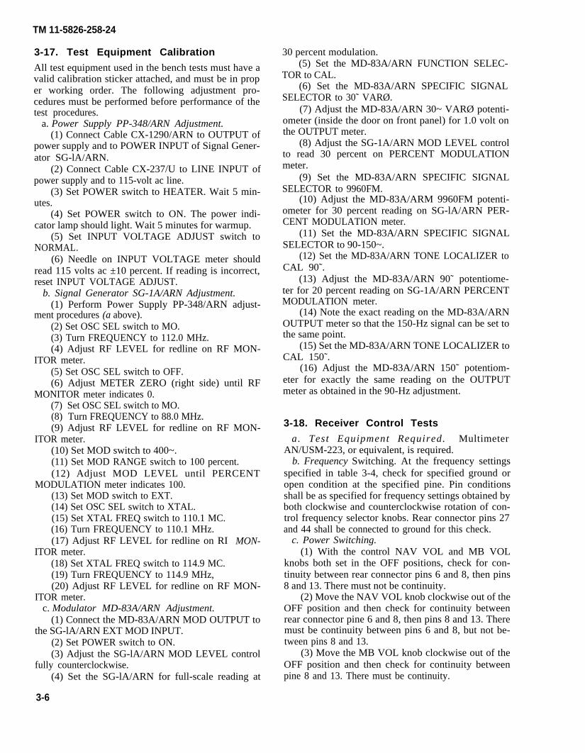
3-17. Test Equipment Calibration
All test equipment used in the bench tests must have avalid calibration sticker attached, and must be in proper working order. The following adjustment pro-cedures must be performed before performance of thetest procedures.
a. Power Supply PP-348/ARN Adjustment.(1) Connect Cable CX-1290/ARN to OUTPUT of
power supply and to POWER INPUT of Signal Gener-ator SG-lA/ARN.
(2) Connect Cable CX-237/U to LINE INPUT ofpower supply and to 115-volt ac line.
(3) Set POWER switch to HEATER. Wait 5 min-utes.
(4) Set POWER switch to ON. The power indi-cator lamp should light. Wait 5 minutes for warmup.
(5) Set INPUT VOLTAGE ADJUST switch toNORMAL.
(6) Needle on INPUT VOLTAGE meter shouldread 115 volts ac ±10 percent. If reading is incorrect,reset INPUT VOLTAGE ADJUST.
b. Signal Generator SG-1A/ARN Adjustment.(1) Perform Power Supply PP-348/ARN adjust-
ment procedures (a above).(2) Set OSC SEL switch to MO.(3) Turn FREQUENCY to 112.0 MHz.(4) Adjust RF LEVEL for redline on RF MON-
ITOR meter.(5) Set OSC SEL switch to OFF.(6) Adjust METER ZERO (right side) until RF
MONITOR meter indicates 0.(7) Set OSC SEL switch to MO.(8) Turn FREQUENCY to 88.0 MHz.(9) Adjust RF LEVEL for redline on RF MON-
ITOR meter.(10) Set MOD switch to 400~.(11) Set MOD RANGE switch to 100 percent.(12) Adjust MOD LEVEL until PERCENT
MODULATION meter indicates 100.(13) Set MOD switch to EXT.(14) Set OSC SEL switch to XTAL.(15) Set XTAL FREQ switch to 110.1 MC.(16) Turn FREQUENCY to 110.1 MHz.(17) Adjust RF LEVEL for redline on RI
ITOR meter.(18) Set XTAL FREQ switch to 114.9 MC.(19) Turn FREQUENCY to 114.9 MHz,
MON-
(20) Adjust RF LEVEL for redline on RF MON-ITOR meter.
c. Modulator MD-83A/ARN Adjustment.(1) Connect the MD-83A/ARN MOD OUTPUT to
the SG-lA/ARN EXT MOD INPUT.(2) Set POWER switch to ON.(3) Adjust the SG-lA/ARN MOD LEVEL control
fully counterclockwise.(4) Set the SG-lA/ARN for full-scale reading at
3-6
30 percent modulation.(5) Set the MD-83A/ARN FUNCTION SELEC-
TOR to CAL.(6) Set the MD-83A/ARN SPECIFIC SIGNAL
SELECTOR to 30˜ VARØ.(7) Adjust the MD-83A/ARN 30~ VARØ potenti-
ometer (inside the door on front panel) for 1.0 volt onthe OUTPUT meter.
(8) Adjust the SG-1A/ARN MOD LEVEL controlto read 30 percent on PERCENT MODULATIONmeter.
(9) Set the MD-83A/ARN SPECIFIC SIGNALSELECTOR to 9960FM.
(10) Adjust the MD-83A/ARM 9960FM potenti-ometer for 30 percent reading on SG-lA/ARN PER-CENT MODULATION meter.
(11) Set the MD-83A/ARN SPECIFIC SIGNALSELECTOR to 90-150~.
(12) Set the MD-83A/ARN TONE LOCALIZER toCAL 90˜.
(13) Adjust the MD-83A/ARN 90˜ potentiome-ter for 20 percent reading on SG-1A/ARN PERCENTMODULATION meter.
(14) Note the exact reading on the MD-83A/ARNOUTPUT meter so that the 150-Hz signal can be set tothe same point.
(15) Set the MD-83A/ARN TONE LOCALIZER toCAL 150˜.
(16) Adjust the MD-83A/ARN 150˜ potentiom-eter for exactly the same reading on the OUTPUTmeter as obtained in the 90-Hz adjustment.
3-18. Receiver Control Tests
a. Test Equipment Required. MultimeterAN/USM-223, or equivalent, is required.
b. Frequency Switching. At the frequency settingsspecified in table 3-4, check for specified ground oropen condition at the specified pine. Pin conditionsshall be as specified for frequency settings obtained byboth clockwise and counterclockwise rotation of con-trol frequency selector knobs. Rear connector pins 27and 44 shall be connected to ground for this check.
c. Power Switching.(1) With the control NAV VOL and MB VOL
knobs both set in the OFF positions, check for con-tinuity between rear connector pins 6 and 8, then pins8 and 13. There must not be continuity.
(2) Move the NAV VOL knob clockwise out of theOFF position and then check for continuity betweenrear connector pine 6 and 8, then pins 8 and 13. Theremust be continuity between pins 6 and 8, but not be-tween pins 8 and 13.
(3) Move the MB VOL knob clockwise out of theOFF position and then check for continuity betweenpine 8 and 13. There must be continuity.

Table 3-4.
TM 11-5826-258-24
3-7

TM 11-5826-258-24
d. Marker Beacon Sensitivity Switching.(1) Place the MB SENS switch in the LO position
and then check for continuity between rear connectorpins 12 and 14. There must not be continuity.
(2) Place the MBS SENS switch in the HI positionand then check for continuity between rear connectorpins 12 and 14. There must be continuity.
e. VOR/Marker Beacon Test Switching.(1) Place the VOR/MB TEST switch in the test
(down) position and then check for continuity betweenrear connector pins 10 and 16. There must be continu-ity.
(2) With the VOR/MB TEST switch not in the testposition (up), check for continuity between rear con-nector pins 10 and 16. There must not be continuity.
f. VOR/LOC Audio Volume Adjustment.(1) Measure the resistance between rear connector
pins 1 and 3. The resistance must be 750 to 1250ohms.
(2) Measure the resistance between rear connectorpins 1 and 2 while rotating the NAV VOL knob fromthe OFF position to its fully clockwise position. The re-sistance must increase smoothly from 0 ohm to be-tween 900 and 1100 ohms with no intermittency.
g. Marker Beacon Audio Volume Adjustment.(1) Measure the resistance between rear connector
pins 17 and 19. The resistance must be 110 to 190ohms.
(2) Measure the resistance between rear connectorpins 17 and 18 while rotating the MB VOL knob fromthe OFF position to its fully clockwise position. The re-sistance must increase smoothly from 0 ohms to be-tween 135 and 165 ohms with no intermittency.
h. Panel Lighting Test.(1) Test equipment required. Hewlett-Packard
Model 6266B Power Supply, or equivalent, is required.(2) General test conditions. The receiver control
chassis shall be grounded.(3) Test. Apply 27.5 vdc power to the receiver
control rear connector (+ at pin 21, - at pin 10). Bothpanel lamps must be fully illuminated.
3-19. VOR Bench Tests
a. Test Setup. All VOR and LOC bench tests are per-formed with the test setup shown in figure 3-1. CO-axial cables with 52 ohms characteristic impedance areused for all rf and modulation interfaces. Test set cableplugs P2, P3, and P7 mate with jacks J2, J3, and J7 onReceiver Adapter Cable CX-13034/AR. Plugs P11001and P12002 on the receiver adapter cable connect toJ11001 and J12002 on the receiver panel.
b. Initial Switch Settings. Before performing theVOR/LOC receiver section bench test procedures, setthe controls of all items of test equipment as follows:Radio Test Set AN/ARM-92B:
OFF/PWR/TEST PWRMODE 400 Hz
3-8
BEARINGCompass headingFLAG LOADSENSIND TESTDEVIATIONAUDIOOBSCONTROL frequency
Audio Output Meter TS-585/U:IMPEDANCEMULTIPLY BY
Modulator MD-83A/ARN:POWERTONE LOCALIZERPHASE ANGLE SELECTORFUNCTION SELECTORSPECIFIC SIGNAL SELECTORMASTER ATTENUATOR1000˜
Power Supply PP-348/ARN:POWERINPUT VOLTAGE ADJUST
Signal Generator SG-1A/ARN:FREQUENCYOUTPUT LEVELMOD RANGEMODXTAL FREQOSC SEL
BRG04LOV/L RCVR0V/LN(0°)114.90 MHz
X1, 15010
ONOFF0°CAL30~VAR ØCounterclockwiseOFF
ONNORMAL
114.901K100%EXT114.9 MCXTAL
c.
NOTEThe FREQUENCY dial must be adjusted forpeak on RF MONITOR meter, and the RFLEVEL control must be set for a redline indi-cation on RF MONITOR meter.VOR Test Signal. The VOR test signal is an rf car-
rier, amplitude modulated simultaneously 30 percentby a 9960 Hz subcarrier which is in turn frequencymodulated at a deviation ratio of 16 by a 30-Hz ref-erence phase signal, and 30 percent by a 30-Hz vari-able phase signal which can be varied in phase withrespect to the 30 Hz reference phase signal. When thetest procedure calls for a VOR test signal, proceed asfollows:
(1) Set Power Supply PP-348/ARN POWERswitch to ON.
(2) Set Signal Generator SG-1A/ARN controls asfollows:
(a) FREQUENCY to 114.90.(b) OUTPUT LEVEL to 1K (1000 microvolts).(c) MOD RANGE to 30%.(d) MOD to EXT.(e) EXTAL FREQ to 114.9 MC.
(3) Set Modulator MD-83A/ARN controls asfollows:
(a) POWER to ON.(b) TONE LOCALIZER to 0.(c) 1000~ to OFF.(d) FUNCTION SELECTOR to CAL(e) SPECIFIC SIGNAL SELECTOR to 30~VAR
Ø

TM 11-5826-258-24
Figure 3-1. Bench Test Setup, VOR/LOC.
3-9

TM 11-2826-258-24
(f) PHASE ANGLE SELECTOR to 0.(4) Set Radio Test Set AN/ARM-92B controls as
follows:(a) OFF/PWR/TEST to PWR.(b) Frequency dial to 114.90 MHz.(c) IND TEST to V/L RCVR.(d) BEARING (switch) to BRG.(e) BEARING (control) to 0.
(5) Set Audio Output Meter TS-585/UIMPEDANCE to Xl, 150 and MULTIPLY by 1.0.
(6) Adjust SG-lA/ARM FREQUENCY dial forpeak on RF MONITOR meter.
(7) Adjust SG-lA/ARN RF LEVEL control forredline indication on RF MONITOR meter,
(8) Adjust SG-lA/ARN MOD LEVEL control forfull scale (30 percent) indication on PERCENTMODULATION meter.
(9) Set MD-83A/ARN SPECIFIC SIGNALSELECTOR to 9960FM. The SG-1A/ARN PERCENTMODULATION meter should indicate 30 percent.
NOTEIf a 30-percent indication is not obtained inthe preceding step, open the potentiometerdoor on the MD-83A/ARN front panel andadjust the 9960 FM potentiometer for a 30-percent indication on the SG-lA/ARN PER-CENT MODULATION meter.(10) Set SG-lA/ARN MOD RANGE switch to
100%.(11) Set MD-83A/ARN FUNCTION SELECTOR
to ODR.d. RF Sensitivity Test.
(1) Set rf signal generator for a 5-microvolt outputsignal at 114.90 MHz modulated 30 percent by 1000Hz as follows:
(a) Rf signal generator MOD switch to 1000~.(b) Rf signal generator MOD RANGE switch to
30%.(c) Adjust rf signal generator MOD LEVEL
control for 30 percent indication on PERCENTMODULATION meter.
(2) Set radio test frequency to 114,90 MHz.(3) Note audio output meter reading in decibels.(4) Turn rf signal generator MOD switch to EXT.
Audio output meter shall read at least 6 db lower thannoted reading.
(5) Repeat steps (1) thru (4) with Radio Test Set,and rf Signal Generator set to thequencies:
106.00 111.30 114.60109.10 112.40 115.70110.20 113,50 116.80
NOTE
following fre-
117.90117.95
If unusual or defective receiver performancehas been noted on a specific channel frequen-cy, perform the rf sensitivity test on that fre-quency. Use Electronic Counter, Digital
3-10
e.
Readout AN/USM-207, or equivalent, tomonitor the test frequency output of SignalGenerator SG-1A/ARN.Audio Output Test.
(1) Set rf signal generator for a 1000-microvoltoutput signal at 114.90 MHz modulated 10 percent by1000 Hz.
(2) The audio output meter shall read at least 50milliwatts.
f. Agc Flatness Test.(1) Set rf signal generator for a 1000-microvolt
output signal at 114.90 MHz modulated 30 percent by1000 Hz.
(2) Note audio output meter reading in db.(3) Slowly vary the output the rf signal generator
between 10 microvolt and 10,000 (10K) microvolt.The audio output meter shall not vary more than k 10db from noted reading.
g. VOR Course Width Test.(1) Set up a standard VOR test signal.(2) Set the radio test set BEARING switch to
OBS.(3) Set the radio test set OBS control to N (north).
NOTEThe OBS indicator on the radio test set mustbe an ID-1347C/ARN.(4) Set the modulator PHASE ANGLE
SELECTOR for O on radio test set DEVIATION meter,Note the PHASE ANGLE SELECTOR setting.
(5) Adjust the modulator PHASE ANGLESELECTOR for 150 microampere (positive) deflectionon radio test set DEVIATION meter. Note the PHASEANGLE SELECTOR setting.
(6) Adjust the modulator PHASE ANGLE SE-LECTOR for 150 microampere (negative) deflectionon radio test set DEVIATION meter, Note the PHASEANGLE SELECTOR setting.
(7) Compare the three PHASE ANGLE SELEC-TOR readings. The second and third readings must be10° ±2° from the first reading.
h. VOR to/From Ambiguity Test.(1) Set up a standard VOR test signal.(2) Set the PHASE ANGLE SELECTOR on the
modulator to 0.(3) Set the OBS control on the radio test set to N.(4) The TO-FROM meter on the radio test set
must indicate between 500 and 1200 microampere tothe left of zero.
(5) Reduce the output level from the rf signal gen-erator to 5 microvolt.
(6) The TO-FROM meter on the radio test setmust indicate between 500 and 1200 microamperes tothe left of zero.
(7) Reset the output level of the rf signal genera-tor to 1000 microvolt.
(8) Set the PHASE ANGLE SELECTOR on the

TM 11-5826-258-24
modulator to 180°.(9) The TO-FROM meter on the radio test set
must indicate between 500 and 1200 microampere tothe right to zero.
i. VOR Alarm Flag Test.(1) Set up a standard VOR test signal.(2) Set the PHASE ANGLE SELECTOR on the
modulator to 0.(3) Set the BEARING selector on the radio test set
to 0°.(4) The FLAG meter on the radio teat set must in-
dicate 220 microampere minimum.(5) Set the FUNCTION SELECTOR switch on the
modulator to CAL.(6) Set the SPECIFIC SIGNAL SELECTOR
switch on the modulator to 30~VAR Ø.(7) The FLAG meter on the radio teat set must in-
dicate 180 microampere or less.(8) Set the SPECIFIC SIGNAL SELECTOR
switch on the modulator to 9960FM.(9) The FLAG meter on the radio teat set must in-
dicate 180 microampere or less.j. VOR Runout Error Test.
(1) Set up a standard VOR test signal.(2) Set the BEARING switch on the radio test set
to BRG.(3) Set the FUNCTION SELECTOR switch on the
modulator to ODR.(4) Set the BEARING selector on the radio test set
to 0O.(5) Set the PHASE ANGLE SELECTOR on the
modulator for 0 on the radio test set DEVIATIONmeter.
(6) The position of the PHASE ANGLE SELEC-TOR on the modulator must be within * 3° of theBEARING control setting.
(7) The RMI pointer on the radio test set must in-dicate within ±5° of the BEARING control setting.
(8) Repeat (4) through (7) above substituting thefollowing angles in (4): 30°, 60°, 90°, 120°, 150°,180°, 210°, 240°, 270°, 300°, 330°.
(9) Set the PHASE ANGLE SELECTOR on theMD-83A to 300.
(10) Set the COMPASS SIMULATOR on theAN/ARM-92B to the following headings 0°, 60°,90°, 150°, 180°, 210°, 270°, and 330°.The RMI pointer on the AN/ARM-92B must indicate30° ±5° for all the above headings.
k. VOR Self-Test.(1) Set up a standard VOR test signal.(2) Set the PHASE ANGLE SELECTOR on the
modulator to 0.(3) Set the BEARING switch on the radio test set
to OBS.(4) Set the OBS control on the radio test set to
315°.
(5) Actuate the TEST switch on the radio test setCONTROL.
(6) The DEVIATION meter on the radio test setmust indicate 0 ± 40 microampere. (Allow time forthe meter to settle.)
(7) The TO-FROM meter on the radio test setmust indicate at least 500 microampere to the left ofzero.
(8) The FLAG meter on the radio test set must in-dicate 220 microampere minimum.
(9) The RMI pointer on the radio test set mustpoint between 310 and 320 degrees.
(10) Release the TEST switch.
3-20. LOC Bench Tests
a. Test Setup. The LOC bench tests are performedwith the same test setup as used for VOR bench tests(fig. 4-l).
b. Initial Switch Settings. The initial switch set-tings for the localizer bench tests are the same as forthe VOR bench tests except that the radio teat setCONTROL frequency must be set to 110.10 MHz.
c. Standurd LOC Test Signal. The standard LOCtest signal is an rf carrier amplitude modulated simul-taneously with 90 ± 0.27 Hz and 150 ± 0.45 Hz so thatthe sum of the two modulation percentages equals 40± 2 per cent. When the test procedure calls for a stand-ard LOC teat signal, proceed as follows:
(1) Set Power Supply PP-348/ARN POWERswitch to ON.
(2) Set Signal Generator SG-lA/ARN controls asfollows
(a) FREQUENCY to 110.10.(b) OUTPUT LEVEL to lK (1000 microvolts).(c) MOD RANGE to 30%.(d) MOD to EXT.(e) XTAL FREQ to 110.0 MC.
(3) Set Modulator MD-83A/ARN controls as fol-lows:
(a) POWER to ON.(b) TONE LOCALIZER to CAL 90~.(c) 1000˜ to OFF.(d) FUNCTION SELECTOR to TONE LOC.
(4) Set Radio Test Set AN/ARM-92B controls asfollows:
(a) OFF/PWR/TEST to PWR.(b) Frequency dial to 110.10.(c) IND TEST to V/L RCVR.
(5) Set Audio Output Meter TS-585/U IMPED-ANCE to X1, 150 and MULTIPLY by 10.
(6) Adjust SG-lA/ARN FREQUENCY dial forpeak on RF MONITOR meter.
(7) Adjust SG-1A/ARN RF LEVEL control forredline indication on RF MONITOR meter.
(8) Adjust SG-lA/ARN MOD LEVEL control for20 percent indication on PERCENT MODULATION
3-11

TM 11-5826-258-24
meter.(9) Set MD-83A/ARN TONE LOCALIZER switch
to CAL 150˜. The SG-lA/ARN PERCENT MODULA-TION meter should indicate 20%.
NOTEIf a 20 percent indication is not obtained inthe preceding step, open the potentiometerdoor on the MD-83A/ARN front panel andadjust the 150˜ potentiometer for a 20% in-dication on the SG-lA/ARN PERCENTMODULATION meter.(10) Set SG-lA/ARN MOD RANGE switch to
100%.(11) Set MD-83A/ARN TONE LOCALIZER to 0.
d. LOC Centering Test.(1) Set up a standard LOC test signal (para 3-20a,
b, and c).(2) The AN/ARM-92B DEVIATION meter shall
indicate 0 ± 10 microamperes.e. LOC Sensitivity Test.
(1) Set up a standard LOC teat signal.(2) Set the MD-83A/ARN TONE LOCALIZER to
4DB (right side) for 90 Hz predomination.(3) The AN/ARM-92B DEVIATION meter shall
indicate between 70 and 110 microampere right ofzero.
(4) Set the MD-83A/ARN TONE LOCALIZER to4 DB (left side) for 150 Hz predomination.
(5) The AN/ARM-92B DEVIATION meter shallindicate between 70 and 110 microampere left ofzero.
f. LOC Alarm Flag Test.(1) Set up a standard LOC test signal (para 3-20a,
b, and c).(2) The AN/ARM-92B FLAG meter shall indicate
220 microamperes minimum.(3) Set the MD-83A/ARN TONE LOCALIZER
switch to CAL 150~.(4) The AN/ARM-92B FLAG meter shall indicate
180 microampere or less.(5) Set the MD-83A/ARN TONE LOCALIZER
switch to CAL 90~.(6) The AN/ARM-92B FLAG meter shall indicate
180 microampere or less.
3-21. Glideslope Bench Tests
a. Test Setup. The glideslope bench tests are per-formed with the test setup shown in figure 3-2. Stand-ard 52-ohm coaxial cables with mating connectors areused for all rf and modulation interfaces. AdapterCable CX-13034/AR connects the receiver to RadioTest Set AWARM-92B.
b. Initial Switch Settings. Before performing theglideslope section bench test procedures, the controlsof all items of test equipment should be set as follows:Radio Test Set AN/ARM-92B
OFF/PWR/TEST OFFMODE 400 HZBEARING control 0BEARING switch BRGFLAG LOAD 4SENS LOIND TEST GS RCVRDEVIATION 0CONTROL frequency 109.30
Radio Test Set AN/ARM-5POWER STAND BYOMNI TRACK 0MODULATION AMP LOC IDENTIFIER OFFATTENUATOR 0M C B
Frequency Converter AN/ARM-69POWER OFFFREQ MC 332.0
c. Glideslope Test Signal. The glideslope teat signalis an rf carrier amplitude-modulated 22.5 percent by a90-Hz signal and 22.5 percent by a 150-Hz signal. Therf carrier supplied by Radio Teat Set AN/ARM-5 isconverted in frequency by Frequency ConverterAN/ARM-69. The two modulation signals can bevaried in relative amplitude by the MODULATIONand ATTENUATOR controls on the AN/ARM-5. Theglideslope test signal is set upon the bench test equip-ment as follows:
(1) Set the AN/ARM-69 power switch to ON. Thepower lamp shall light.
(2) Set the AN/ARN-5 controls as follows(a) POWER – STANDBY switch to POWER.(b) MC switch to B.(c) MODULATION switch to 90~.(d) Adjust 90˜ MOD for 22.5 on %M meter.(e) MODULATION switch to 150~.(f) Adjust 150˜ MOD for 22.5 on %M meter.(g) MODULATION switch to AMP LOC
The %M meter should read approximately 40.(3) Set the AN/ARM-69 FREQ MC switch to
332.0.(4) Adjust RF LEVEL SET until LEVEL SET
meter pointer is centered.(5) Remove Cable CG-409/U (without attenuator)
from the AN/ARM-5 RF OUTPUT 1 VOLT jack andconnect to the RF OUTPUT ATTEN jack.
(6) Set AN/ARM-92B OFF/PWR/TEST switch toPWR.
d. Rf Sensitivity Test,(1) Adjust the AN/ARM-5 ATTENUATOR to 50
microvolt.(2) Set MODULATION switch to AMP LOC (3) The AN/ARM-92B DEVIATION meter must
indicator 90 ± 30 microamperes right of zero.
3-12

TM 11-5826-258-24
Figure 3-2. Bench Test Setup, Glideslope.
3-13

TM 11-5826-258-24
(4) Se t AN/ARM-69 FREQ MC andAN/ARM-92B CONTROL frequency to each glide-slope channel in table 3-5 and verify theAN/ARM-92B DEVIATION meter reads 90 ± 30 mi-croampere right of zero at each setting.
(5) Repeat the teat on all frequencies with theAN/ARM-5 MODULATION switch set to AMP The AN/ARM-92B DEVIATION meter mustindicate 90 ± 30 microampere left of zero at each set-ting. Return the controls to 332.0 and 109.30.
e. Course Centering Test.(1) Adjust the AN/ARM-5 ATTENUATOR to 700
microvolts.(2) Set the AN/ARM-5 MODULATION switch to
AMP LO C (3) The AN/ARM-92B DEVIATION meter must
indicate 0 ± 30 microampere.Table 3-5. Frequency Pairs for Glideslope Sensitivity Test
AN/ARM-92BFreq. sel.
(MHz)
108.10108.30108.50108.70108.90109.10109.30109.50109.70109.90
Sig. gen.freq. (mhz)
334.70334.10329.90330.50329.30331.40332.00332.60333.20333.80
AN/ARM-92Bfreq. sel. Sig. gen.
(mhz) freq. (mhz)
110.10 334.40110.30 335.00110.50 329.60110.70 330.20110.90 330.80111.10 331.70111.30 332.30111.50 332.90111.70 333.50111.90 331.10
f. Deflection Sensitivity Test.(1) Adjust the AN/ARM-5 ATTENUATOR to 700
microvolts.(2) Set the AN/ARM-5 MODULATION switch to
AMP LOC (3) The AN/ARM-92B DEVIATION meter must
indicate 90 ± 30 microampere right of zero.(4) Set the AN/ARM-5 MODULATION switch to
AMP LOC (5) The AN/ARM-92B DEVIATION meter must
indicate 90 ± 30 microampere left of zero.g. Agc Response Test.
(1) Adjust the AN/ARM-5 ATTENUATOR to 700microvolt.
(2) Set the AN/ARM-5 MODULATION switch toAMP LOC
(3) Note the reading on the AN/ARM-92BDEVIATION meter. The indication must be 90 ± 30microamperes right of zero.
(4) Adjust the AN/ARM-5 ATTENUATOR slowlybe tween 100 and 10 ,000 mic rovo l t . TheAN/ARM-92B DEVIATION meter must indicatewithin 30 microampere of the previously noted read-ding throughout the entire output level range.
h. Warning Signal Test.
(1) Adjust the AN/ARM-5 ATTENUATOR to 700microvolt.
CAUTIONDisconnect Cables CG-409/U and CG-483/Ufrom the AN/ARM-69 DEMOND and MODjacks except while performing the warningsignal teat. Maintain approximately 22.5percent modulation (each tone) on theAN/ARM-5.(2) Set the AN/ARM-5 MODULATION switch to
90˜ .(3) Adjust the AN/ARM-5 90˜ MOD control for
22.5 on %M meter. The AN/ARM-92B FLAG metermust indicate leas than 180 microampere.
(5) Adjust the AN/ARM-5 150˜ MOD control for22.5 on %M meter. The AN/ARM-92B FLAG metermust indicate less than 180 microampere.
(6) Connec t Cab le CG-409/U be tweenAN/ARM-5 DEMOD jack and AN/ARM-69 DEMONDjack.
(7) Connect Cable CG-433/U be tweenAN/ARM-5 EXT MOD terminals and AN/ARM-69MOD jack.
(8) Set the AN/ARM-5 MODULATION switch toAMP LOC
(9) Set the AN/ARM-5 DEMOD adjust (screw-driver adjustment) for 80 on %M meter. TheAN/ARM-92B FLAG meter must indicate 220 micro-ampere minimum.
3-22. Marker Beacon Bench Testsa. Test Setup. The marker beacon bench tests are
performed with test setup shown in figure 3-3.b. Initial Switch Settings. Before performing the
marker beacon bench test procedures, set the controlsof all items of teat equipment as followsRadio Test Set AN/ARM-92B
0FF/PWR/TEST PWRMODE 400 HZBEARING control 0BEARING switch BRGFLAG LOADSENS LOIND TEST GS RCVRDEVIATION 0CONTROL frequency 109.30AUDIO MB
Audio Oscillator AN/URM-127ATTENUATOR X1OUTPUT CONTROL MidrangeFREQ. RANGE MULTIPLIER X10Frequency control dial 40FREQ. METER switch ONPOWER switch ON
RF Signal Generator AN/USM-44Power switch ONATTEN. 5 mv. (-33 dBm)MOD SELECTOR EXT MODFREQUENCY RANGE C (42-90 MHz)FREQUENCY Adjust to 75 MHz (using
3-14

TM 11-5826-258-24
Figure 3-3. Bench Test Setup, Marker.
3-15

TM 11-5826-258-24
Electronic CounterAN/USM-207 DigitalReadout)
AMP. TRIMMER Peak on meterOUTPUT LEVEL SET LEVEL (red arrow)MOD LEVEL 80%
Audio Output Meter TS-585/UIMPEDANCE X1, 150MULTIPLY BY 10
c. Marker Test Signal. The marker test signal is a75-MHz rf carrier amplitude-modulated 80 percent bya single tone of 400 Hz, 1300 Hz, or 3000 Hz.
d. Audio Output Power Test.(1) Adjust the AN/USM-44 FREQUENCY control
for a peak reading on Audio Output Meter TS-585/U.(2) Adjust the AN/USM-44 ATTEN. dial until the
blue lamp (outer) on the AN/ARM-92B glows dimly.(3) Note the reading in millivolts on the
AN/USM-44 ATTEN, dial; then adjust the ATTEN.dial to 10 times the noted reading.
(4) The TS-585/U must indicate at least 40milliwatts.
e. Lamp Actuation Test.(1) Adjust the AN/URM-127 frequency control to
40 (400 Hz).(2) Adjust the AN/USM-44 ATTEN. dial to 50
millivolts(3) The blue OUTER marker lamp on the
AN/ARM-92B must light. The amber and white lampsmust not light.
(4) Adjust the AN/URM-127 frequency control to130 (1300 Hz).
(5) The amber MIDDLE marker lamp on theAN/ARM-92B must light. The blue and white lampsmust not light.
(6) Set the AN/ARM-127 FREQ. RANGEMULTIPLIER to X100.
(7) Adjust the AN/URM-127 frequency control to30 (3000 Hz).
(8) The white AIRWAY marker lamp on theAN/ARM-92B must light. The blue and amber lampsmust not light.
f. Threshold Sensitivity Test.(1) Set the AN/ARM-92B SENS switch to HI.(2) Set the AN/URM-127 FREQ. RANGE
MULTIPLIER to X10.(3) Set the AN/URM-127 frequency control to
130 (1300HZ).(4) Adjust the AN/USM-44 ATTEN. dial until
amber lamp (middle) on AN/ARM-92B glows dimly.(5) The rf output level indicated on the
AN/USM-44 ATTEN. dial must be between 250 and1000 microvolts.
(6) Set the AN/ARM-92B SENS switch to LO.(7) Adjust the AN/USM-44 ATTEN. dial until
amber lamp on AN/ARM-92B glows dimly.(8) The rf output level indicated on the
AN/USM-44 ATTEN. dial must be between 1.0 and3.0 millivolts.
Section VII. ALTERNATE VOR/LOC BENCH TEST
3-23. General
This section presents an alternate VOL/LOC benchteat procedure using Radio Test Set AN/ARM-5A.
a. Test Setup. All VOR and LOC bench teats are per-formed according to the test setup in figure 3-4. Coax-ial cables with 52-ohm characteristic impedance areused for all rf and modulation interfaces. Test set cableplugs P2, P3, and P7 mate with jacks J2, J3, and J7 onReceiver Adapter Cable CX-13034/AR. Plugs P11001and P12002 on the receiver adapter cable connect toJ11001 and J12002 on the receiver panel.
b. Initial Switch Settings. Before performing theVOL/LOC receiver section bench test procedures, setthe controls of all items of test equipment as follows:Radio Test Set AN/ARM-92B:
Control SettingOFF/PWR/TEST PWRMODE 400HzBEARING switch BRGBEARING control 0COMPASS SIMULATOR N(0 degrees)FLAG LOAD 4SENS LOIND TEST V/L RCVRDEVIATION 0
3-14
Control Setting
AUDIO V/LOBS COURSE CARD N(0°)CONTROL frequency 114.90
Audio Output Meter TS-585/U:Control Setting
IMPEDANCE X1, 150MULTIPLY BY 100
Radio Test Set AN/ARM-5A:Control Setting
POWER ONOMNI TRACK 0MODULATION OMNIIDENTIFIER OFFMC B(114.90)ATTENUATOR µV lK30˜ MOD Full ccw9960˜ MOD Full ccw90˜ MOD Full ccw150˜ MOD Full ccwRF meter Adjust ZERO SET for 0.%M (MODULATION) meter Adjust ZERO SET for 0.RF LEVEL SET Adjust for red level set lineMODULATION Set to 1000˜.1000˜ MOD Adjust for 30% (0-100 scale)
on %M meter.
c. Test Procedure. After the test equipment has

TM 11-5826-258-24
Figure 3-4. Bench Test Setup for VOR/LOC Tests usingAN/ARM-5A.
3-17

TM 11-5826-258-24
been setup and the controls set as in b above, make thefollowing control settings on the AN/ARM-5A:
Control SettingMODULATION Set to 9960˜.9960˜ MOD Adjust for 30% (green
arrow) on %M meter.MODULATION Set to 30˜.30˜ MOD Adjust for 30% (green
arrow) on %M meter.
MODULATION Set to 90˜.90˜ MOD Adjust for 20% (red dot) on
%M meter.
MODULATION set for 150˜.150˜ MOD Adjust for 20% (red dot) on
%M meter.
NOTERepeat adjustment of 90˜ MOD and 150˜MOD until the same reading is obtained.
3-24 VOR Bench Tests
a. Rf Sensitivity Test.(1) Set the AN/ARM-5A for a 5-microvolt output
signal at 114.90 MHz modulated 30% by 1000 Hz asfollows:
(a) Set ATTENUATOR µv control to 5.(b) Set MODULATION control to 1000~.
(2) Note the TS-585/U meter reading in decibels,(3) Turn the AN/ARM-5A MODULATION switch
to EXT. The TS-585/U shall indicate at least 6 dblower than the noted reading.
NOTEIf unusual or defective receiver performancehas been noted on a specific channel frequen-cy, perform the rf sensitivity test on that fre-quency. Use the alternate rf sensitivity testgiven in paragraph 3-26.
b. Audio Output Test.(1) Set the AN/ARM-5A for a lK µV output sig-
nal at 114.90 MHz modulated 10 percent by 1000 Hz.(2) Set MODULATION control to 1000˜.(3) Adjust 1000˜ MOD control for 10 percent
modulation (0-100 scale).(4) Set ATTENUATOR ˜V to 1k.(5) The TS-585/U shall indicate at least 50 milli-
wa t t .c. Agc Flatness Test.
(1) Set AN/ARM-5A for a 1K-microvolt outputsignal at 114.90 Mz modulated 30 percent MHz by1000 Hz.
(2) Set the AN/ARM-5A 1000˜ MOD control for30 percent (0-100 scale).
(3) Note TS-585/U meter indication in db.(4) Slowly vary the output of the AN/ARM-5A
ATTENUATOR µV between 10 microvolt and 10Kmicrovolt. The TS-585/U shall not vary more than±10 db from the noted indication.
d. VOR Course Width Test.(1) Set the MODULATION control on the
AN/ARM-5A to OMNI.(2) Set the AN/ARM-92B BEARING switch to
OBS.(3) Set the AN/ARM-92B OBS course card to N
(North).(4) Set the OMNI TRACK control on the
AN/ARM-5A to 0.(5) Set ATTENUATOR µV to 1K.(6) Adjust the OBS knob on the AN/ARM-92B to
zero (µa) indication on the DEVIATION meter.(7) Note the OBS course card reading.(8) Adjust the OBS knob on the AN/ARM-92B for
a 150 (µa) right indication on the DEVIATION meter.The OBS course card reading must be -10° ± 3° fromthe reading in (7) above.
(9) Repeat (7) above for 150 (µa) left indication.The OBS course card shall be +10° ±3° from thereading (7) above.
e. VOR TO/FROM Ambiguity Test.(1) Set the OBS control on the AN/ARM-92B to
N.(2) The TO-FROM meter on the AN/ARM-92B
must indicate greater than 500 microampere to theleft of zero.
(3) Set the AN/ARM-5A ATTENUATOR µv to 5.(4) The TO-FROM meter on the AN/ARM-92B
must indicate greater than 500 microamperes to theleft of zero.
(5) REset the ATTENUATOR µv of theAN/ARM-5A to 1K.
(6) Set the OMNI TRACK switch on theAN/ARM-5A to 180°.
(7) The TO-FROM meter on the AN/ARM-92Bmust indicate greater than 500 microampere to theright of zero.
f. VOR Alarm Flag Test.(1) Set the OMNI TRACK switch on the
AN/ARM-5A to 0.(2) Set the BEARING se lec tor on the
AN/ARM-92B to 0.( 3 ) S e t t h e B E A R I N G s w i t c h o n t h e
AN/ARM-92B to BRG.(4) The FLAG meter on the AN/ARM-92B must
indicate 220 microampere minimum.(5) Set the MODULATION switch on the
AN/ARM-5A to 30˜.(6) The FLAG meter on the AN/ARM-92B must
indicate 180 microampere or leas.(7) Set the MODULATION switch on the
AN/ARM-5A to 9960˜.(8) The FLAG meter on the AN/ARM-92B must
indicate 180 microampere or less.g. VOR Runout Error Test.
(1) Set the MODULATION switch on the
3-18

AN/ARM-5A to OMNI.(2) Set the BEARING selector
AN/ARM-92B to 0.(3) Set the OMNI TRACK switch
AN/ARM-5A to 0.
on the
on the
(4) The DEVIATION meter on the AN/ARM-92Bshall indicate zero ± 120 microampere (equivalent to±5°).
(5) The RMI pointer on the AN/ARM-92B mustindicate within 70 of the BEARING selector setting.
(6) Repeat (2) through (5) above substituting thefollowing angles in (2) and (3) above:30°, 60°, 90°, 120°, 150°, 180°, 210°, 240°, 270°300°, and 330°
(7) Set the OMNI TRACK switch on theAN/ARM-5A to 30°.
(8) Set the COMPASS SIMULATOR on theAN/ARM-92B to the following settings0°, 60°, 90°, 150°, 180°, 210°, 270°, and 330°.
(9) The RMI pointer on the AN/ARM-92B mustindicate 30° ± 7° for all the above settings.
h. VOR Self-Test.(1) Set the OMNI TRACK switch of the
AN/ARM-5A to 0.( 2 ) S e t t h e B E A R I N G s w i t c h o n t h e
AN/ARM-92B to OBS.(3) Set the OBS control on the AN/ARM-92B to
315°.(4) Actuate the TEST switch on the
AN/ARM-92B CONTROL panel.(5) The DEVIATION meter on the AN/ARM-92B
must indicate zero ±120 microampere. (Allow timefor the meter to settle.)
(6) The TO-FROM meter on the AN/ARM-92Bmust indicate greater than 500 microampere to theleft of zero.
(7) The FLAG meter on the AN/ARM-92B mustindicate 220 microampere minimum.
(8) The RMI pointer on the AN/ARM-92B mustpoint between 308 and 322 degrees.
(9) Release the TEST switch.
3-25. LOC Bench Tests
a. Test Setup. The LOC bench test are performedwith the same test setup as used for VOR bench tests(fig. 3-4).
b. Initial Switch Settings. The initial switch set-tings for the localizer bench tests are the same as forthe VOR bench tests except that the AN/ARM-92BCONTROL FREQUENCY must be set to 110.90 MHz.
c. The AN/ARM-5A is setup as described in para-graph 3-23b and c.
NOTEBefore performing the LOC bench tests, besure the 90˜ and 150˜ modulation percent-ages are set to exactly 20 percent each. Set
TM 11-5826-258-24
the AN/ARM-5A MC switch to A (110.9)MHz).
d. LOC Centering Test.(1 ) Se t the Modula t ion swi t ch on the
AN/ARM-5A to AMP LOC (2) Set the ATTENUATOR µv control to 1K.(3) The AN/ARM-92B DEVIATION meter shall
indicate 0 ± 10 microampere.e. LOC Deflection Sensitivity Test.
(1) Set the MODULATION switch on theAN/ARM-5A to AMP LOC
(2) The AN/ARM-92B DEVIATION meter shallindicate between 60 and 120 microampere left tozero.
(3) Set the MODULATION switch on theAN/ARM-5A to AMP LOC
(4) The AN/ARM-92B DEVIATION meter shallindicate between 60 and 120 microampere right tozero.
f. LOC Alarm Flag Test.(1) Set the MODULATION switch on the
AN/ARM-5A to AMP LOC(2) The AN/ARM-92B FLAG meter shall indicate
220 microampere minimum.(3) Set the MODULATION switch on the
AN/ARM-5A to 150˜.(4) The AN/ARM-92B FLAG meter shall indicate
180 microamperes or less.(5) Set the MODULATION switch on the
AN/ARM-5A to 90˜.(6) The AN/ARM-92B FLAG meter shall indicate
180 microampere or leas.
3-26. VOR/LOC Receiver Sensitivity Test
This procedure provides an alternate test of theVOR/LOC receiver sensitivity for frequencies otherthan 114,90 MHz. The teat is performed with the testsetup in figure 3-5,
a. Initial Switch Settings.Radio Test Set AN/ARM-92B:
Control SettingOFF/PWR/TESTMODEBEARING switchBEARING controlCOMPASS SIMULATORFLAG LOADSENSIND TESTDEVIATIONAUDIOOBS
Audio Output Meter TS-585/U:Control
IMPEDANCEMULTIPLY BY
Signal Generator AN/USM-44:Control
Power SwitchOutput Attenuator (control)
PWR400 HzBRG0N (0 degrees)4L0V/L RCVR0V/LN (0°)
SettingXl, 150100
SettingON1.0 millivolt (-47 dBm)
3-19

TM 11-5826-258-24
Control
MOD. SELECTOR 1000FREQUENCY RANGE (selector) DFREQUENCY Desired frequency. Use
AN/USM-207 to set fre-quency within 1 Khz.
AMP. TRIMMER Peak on meterOUTPUT LEVEL SET LEVEL (red arrow)MOD LEVEL
b. Procedure. In the following procedure 108.00megahertz is used as an example of a selected fre-quency; therefore, set the CONTROL frequency on theAN/ARM-92B to 108.00 Hz. Set the FREQUENCYcontrol to 108.00 megaHertz using the AN/USM-207to set within 1 KHz. Use this procedure to check
VOR/LOC receiver sensitivity at following fre-quencies:
108.00 111.30 114.60 117.90109.10 112.40 115.70 117.95110.20 113.50 116.80
(1) Check to see that there is audio output presenton the TS-585/U.
(2) Set the Output Attenuator control on theAN/USM-44 for an indication of 5 microvolt on theOUTPUT VOLTS-DBM indicator.
(3) Note the indication on the TS-585/U meter.(4) Turn the MOD. SELECTOR on the
AN/USM-44 to CW.(5) The indication on the TS-585/U meter shall be
at least 6 db less than the indication in (3) above.
3-20

TM 11-5826-258-24
Figure 3-5. Bench Test Set, Alternate VOR/LOC Receiver Setsitivity Test.
3-21


TM 11-5026-258-24
APPENDIX AREFERENCES
DA Pam 310-4
DA Pam 310-7SB 11-641
SB38-100
TB 43-0118
TM 11-5017TM 11-5556TM 11-6625-508-10TM 11-6625-522-14-2
TM 1l-6625-588-15
TM 1l-6625-636-12
TM 1l-6625-654-14
TM 11-6625-700-10TM 1l-6625-2709-12TM 38-750TM 55-1500-323-25
TM 740-90-1
Index of Technical Manuals, Technical Bulletins, Supply Manuals (Types 7, 8,and 9),Supply Bulletins, and Lubrication Orders
US Army Equipment Index of Modification Work Orders.Repair and Return Procedures under Reliability Improvement Warranty (RIW) for
AN/ARN-123(V)1, Receiving Set, Radio and the R-1963/ARN, Receiver, Radio.Preservation, Packaging, Packing and Marking Materials, Supplies, and Equipment
Used by the Army.Field Instructions for Painting and Preserving Electronics Command Equipment In-
cluding Camouflage Pattern Painting of Electrical Equipment Shelters.Output Meters TS-585A/U, TS-585B/U, TS-585C/U, and TS-585D/U.Signal Generator SG-13/ARN.Operator’s Manual: Signal Generators AN/USM-44 and AN/USM-44A.Operator’s, Organizational, and General Support Maintenance Manual: Test Oscilla-
tor BC-376P (FSN 6625-098-3668).Organizational, Direct Support, General Support, and Depot Maintenance Manual
Including Repair Parts and Special Tool Lists: Modulator MD-83/ARN.Operator and Organizational Maintenance Manual: Converter, Frequency, Electronic
AN/ARM-69,Operator’s, Organizational, Direct Support, and General Support Maintenance Re-
pair Parts and Special Tools Lists (Including Depot Maintenance Repair Parts andSpecial Tools Lists) for Multimeter AN/USM-223.
Operator’s Manual: Digital Readout, Electronic Counter AN/USM-207.Operator’s and Organizational Manual: Test Set, Radio AN/ARM-92B.The Army Maintenance Management System (TAMMS).Organizational, DS, GS, and Depot Maintenance Manual: Installation Practices for
Aircraft Electric and Electronic Wiring.Administrative Storage of Equipment.
A-1


TM 11-5826-258-24
APPENDIX BMAINTENANCE ALLOCATION
Section I. INTRODUCTION
B-1. General
This appendix provides a summary of the maintenanceoperations for AN/ARN-123(V). It authorizes cate-gories of maintenance for specific maintenance func-tions on repairable items and components and thetools and equipment required to perform each func-tion. This appendix may be used as an aid in planningmaintenance operations.
B-2. Maintenance Function
Maintenance functions will be limited to and definedas follows:
a. Inspect. To determine the serviceability of anitem by comparing its physical, mechanical, and/orelectrical characteristics with established standardsthrough examination.
b. Test. To verify serviceability and to detect in-cipient failure by measuring the mechanical or electri-cal characteristics of an item and comparing thosecharacteristics with prescribed standards.
c. Service. Operations required periodically to keepan item in proper operating condition, i.e., to clean (de-contaminate), to preserve, to drain, to paint, or to re-plenish fuel, lubricant, hydraulic fluids, or com-pressed air supplies.
d. Adjust. To maintain, within prescribed limits, bybringing into proper or exact position, or by settingthe operating characteristics to the specified parame-ters.
e. Align. To adjust specified variable elements of anitem to bring about optimum or desired performance.
f. Calibrate. To determine and cause corrections tobe made or to be adjusted on instruments or teat meas-uring and diagnostic equipments used in precisionmeasurement. Consists of comparisons of two instru-ments, one of which is a certified standard of knownaccuracy, to detect and adjust any discrepancy in theaccuracy of the instrument being compared.
g. Install. The act of emplacing, seating, or fixinginto position an item, part, module (component or as-sembly) in a manner to allow the proper functioning ofthe equipment or system.
h. Replace. The act of substituting a serviceable liketype part, subassembly, or module (component or as-sembly) for an unserviceable counterpart.
i. Repair. The application of maintenance services
(inspect, test, service, adjust, align, calibrate, replace)or other maintenance actions (welding, grinding, rivet-ing, straightening, facing, remachining, or resurfac-ing) to restore serviceability to an item by correctingspecific damage, fault, malfunction, or failure in apart, subassembly, module (component or assembly),end item, or system. This function does not include thetrial and error replacement of running spare typeitems such as fuses, lamps, or electron tubes,
j. Overhaul. That maintenance effort (service/ac-tion) necessary to restore an item to a completely serv-iceable/operational condition as prescribed by mainte-nance standards (i.e., DMWR) in appropriate technicalpublications. Overhaul is normally the highest degreeof maintenance performed by the Army. Overhauldoes not normally return an item to like new condi-tion.
k. Rebuild. Consists of those services/actions neces-sary for the restoration of unserviceable equipment toa like new condition in accordance with original manu-facturing standards. Rebuild is the highest degree ofmateriel maintenance applied to Army equipment.The rebuild operation includes the act of returning tozero those age measurements (hours, miles, etc.) con-sidered in classifying Army equipment/components.
B-3. Column Entries
a. Column 1, Group Number. Column 1 lists groupnumbers, the purpose of which is to identify compo-nents, assemblies, subassemblies, and modules withthe next higher assembly.
b. Column 2, Component/Assembly. Column 2 con-tains the noun names of components, assemblies, subassemblies, and modules for which maintenance is au-thorized.
c. Column 3, Maintenance Functions. Column 3 liststhe functions to be performed on the item listed in col-umn 2. When items are listed without maintenancefunctions, it is solely for purpose of having the groupnumbers in the MAC and RPSTL coincide.
d. Column 4, Maintenance Category. Column 4specifies, by the listing of a “work time” figure in theappropriate subcolumn(s), the lowest level of mainte-nance authorized to perform the function listed in col-umn 3. This figure represents the active time requiredto perform that maintenance function at the indicated
B-1

TM 11-5826-258-24
category of maintenance. If the number or complexityof the tasks within the listed maintenance functionvary at different maintenance categories, appropriate“work timen figures will be shown for each category.The number of task-hours specified by the “work time"figure represents the average time required to restorean item (assembly, subassembly, component, module,end item or system) to a serviceable condition undertypical field operating conditions. This time includespreparation time, troubleshooting time, and qualityassurance/quality control time in addition to the timerequired to perform the specific tasks identified forthe maintenance functions authorized in the mainte-nance allocation chart. Subcolumns of column 4 are asfollows:
C-Operator/CrewO-OrganizationalF-Direct SupportH-General SupportD-Depot
e. Column 5, Tools and Equipment. Column 5 speci-fies by code, those common tool sets (not individualtools) and special tools, teat, and support equipmentrequired to perform the designated function.
f. Column 6, Remarks. Column 6 contains an alpha-betic code which leads to the remark in section IV, Re-marks, which is pertinent to the item opposite the par-ticular code.
B-4. Tool and Test Equipment Require-ments (Sect. III)
a. Tool or Test Equipment Reference Code. Thenumbers in this column coincide with the numbersused in the tools and equipment column of the MAC.The numbers indicate the applicable tool or test equip-ment for the maintenance functions.
b. Maintenance Category. The codes in this columnindicate the maintenance category allocated the tool ortest equipment.
c. Nomenclature. This column lists the noun nameand nomenclature of the tools and test equipment re-quired to perform the maintenance functions.
d. National/NATO Stock Number. This column liststhe National/NATO stock number of the specific toolor test equipment.
e. Tool Number. This column lists the manufactur-er’s part number of the tool followed by the FederalSupply Code for manufacturers (5-digit) in paranthe-ses.
B-5. Remarks (Sect. IV)a. Reference Code. This code refers to the appropri-
ate item in section II, column 6.b. Remarks. This column provides the required ex-
planatory information necessary to clarify items ap-pearing in section II.
(Next printed page is B-3)
B-2

TM 11-5826-258-24
SECTION II MAINTENANCE ALLOCATION CHARTFOR
AN/ARN-123(V)
(1) (2) (3)(4)
(5) (6)GROUP COMPONENT ASSEMBLY
MAINTENANCE CATEGORYMAINTENANCE TOOLS REMARKS
NUMBER FUNCTION C O F H DAND
EQPT.
00 RADIO RECEIVING SET AN/ARN-123(V)1 Test 0.2 2.3 ARepair 0.2 1Inspect 0.1
0 1 RADIO RECEIVER R-2023/ARN-123(V) lnspect 0.1Test 0.2 4 thru 14Replace 0.2 1 BRepair
02 RECEIVER CONTROL C-10048/ARN-123(V) Inspect 0.1Test 0.2 4 thru 14Replace 0.2 1Repair 0.2 C
03 MOUNTING BASE. ELECTRICAL EQUIPMENT Inspect 0.1MT-4834/ARN-123(V) Replace 0.1 1
Repair B
00 RADIO RECEIVING SET AN/ARN-123(V)3 Test 0.2 2. 3 ARepair 0.2 1Inspect 0.1
01 RADIO RECEIVER R-2023/ARN-123(V) Inspect 0.1Test 0.2 4 thru 14Replace 0.2 1 BRepair
02 RECEIVER CONTROL C-10048/ARN-123(V) Inspect 0.1Test 0.2 4 thru 14Replace 0.2 1Repair 0.2 C
03 MOUNTING BASE, ELECTRICAL EQUIPMENT lnspect 0.1MT-4980/ARN-123(V) Replace 0.1 1
Repair B
00 RADIO RECEIVING SET AN/ARN-123(V)4 Test 0.2 2.3 ARepair 0.2 1lnspect 0.1
01 RADIO RECEIVER R-2139/ARN-123(V) lnspect 0.1Test 0.2 4 thru 14Replace 0.2 1 BRepair
02 RECEIVER CONTROL C-10048/ARN-123(V) Inspect 0.1Test 0.2 4 thru 14Replace 0.2 1Repair 0.2 C
03 MOUNTING BASE ELECTRICAL EQUIPMENT Inspect 0.1MT-4834/ARN-123(V) Replace 0.1 1
Repair B
Change 1 B-3
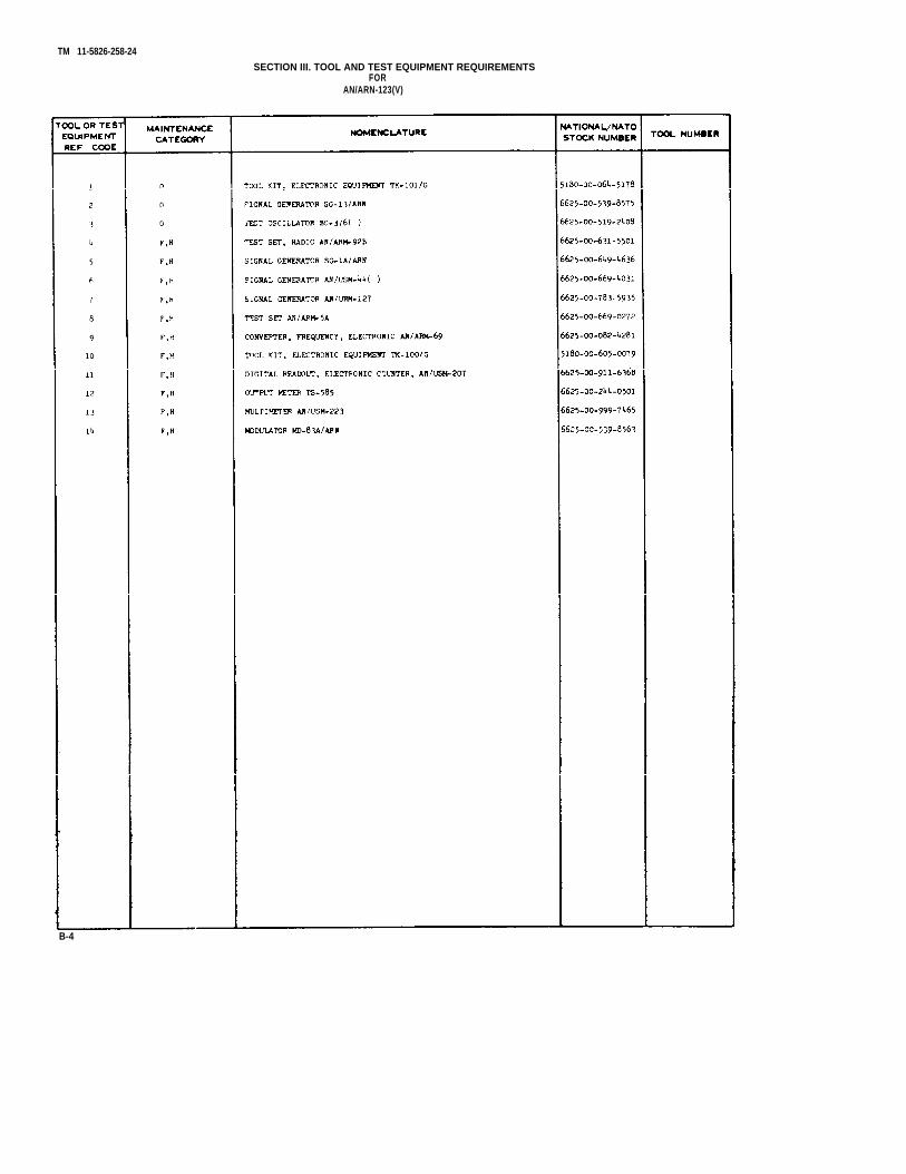
TM 11-5826-258-24
SECTION III. TOOL AND TEST EQUIPMENT REQUIREMENTSFOR
AN/ARN-123(V)
B-4

SECTION IV. REMARKSAN/ARN-123(V)
TM 11-5826-258-24
B-5
U.S. GOVERNMENT PRINTING OFFICE : 1990 - 261-872 (20659)


PIN : 032801-000

This fine document...
Was brought to you by me:
Liberated Manuals -- free army and government manuals
Why do I do it? I am tired of sleazy CD-ROM sellers, who take publicly available information, slap “watermarks” and other junk on it, and sell it. Those masters of search engine manipulation make sure that their sites that sell free information, come up first in search engines. They did not create it... They did not even scan it... Why should they get your money? Why are not letting you give those free manuals to your friends?
I am setting this document FREE. This document was made by the US Government and is NOT protected by Copyright. Feel free to share, republish, sell and so on.
I am not asking you for donations, fees or handouts. If you can, please provide a link to liberatedmanuals.com, so that free manuals come up first in search engines:
<A HREF=http://www.liberatedmanuals.com/>Free Military and Government Manuals</A>
– SincerelyIgor Chudovhttp://igor.chudov.com/