rajasthan rajya vidyut prasaran nigam limited office … · galvanizing and inspection...
TRANSCRIPT
RAJASTHAN RAJYA VIDYUT PRASARAN NIGAM LIMITEDOFFICE OF THE SUPTDG. ENGINEER (Contracts-I)
Corporate Identity Number(CIN): U 40109RJ2000SGC016485Regd.Office: MM Building of RVPN, Old Power House Premises (Back Side),NearRam Mandir, Bani Park,Jaipur-302006
NO. RVPN / SE (Contracts-I) / XEN-l (C)/ ICB-9 / D. ~ ~ 4 Dated
M/S .
Sub: Construction of 400 KV D/C Quad Moose Transmission line from KornaJaisalmer-II against bid Enquiry No. RVPN/ADB/Tranch-2/ICB-9
Dear Sir(s),
The following amendment is hereby made in the bidding document upto the extentindicated hereunder:
1. The design of towers and foundations is included in the scope of thecontractor. As such clause No. 1.1.2 (ii) and (v) of Sub-Section -1 i.e.Technical Specifications of Vol-II of the bidding Document are modified asunder.
(ii) Design, Proto Type Testing, Fabrication, proto inspection, galvanizing andinspection & testing, supply of 400 kV double circuit transmission linetowers and their required body extensions as per CBIP- 3223 (2014 withlatest amendment) and IS-802 (2015 with latest amendment), includingbolts, nuts and washers, anti-theft type bolts & nuts, hangers, D-shackles,U-Bolts, bird guards and all types of tower accessories like phase plates,number plates, danger plates, circuit plates, anti-climbing devices for alltypes of towers & their body extensions, design & supply of extensionsand special tower.
(v) Design of foundations for different types of towers and, casting offoundation for tower footings as per approved design, including specialtowers for different type of soil condition,
2. Chapter 2 "Tower and Accessories" (Vol-II) of the bidding document isreplaced as enclosed herewith.
3. In BOQ 1 to BOQ 4, the items appearing at No. 1.00 (Tower) and 1.20(Supply of bolts and nuts for tower and stubs including step bolts and
nuts & antitheft bolts & nuts) are hereby deleted. The BOQ for theseitems is modified as per Annexure - I to III.
The bidder is required to quote the price of item No. 1.00 toitem No. 1.20 in enclosed BOQ at Annexure I to III, in PDF Formatand upload the same with the Latter of Price Bid. The contract Pricefor the remaining items from 2.00 onwords shall be quoted in therespective BOQs only. For arriving at the total contract price, theprices quoted in Annexure I to III shall be added with the prices quotedin respective BOQ Schedule.
4. Similarly in BOQ 5, the items appearing at No. 3.00, 5.00, 6.00, 7.00,8.00, 9.00 and 10.00 are hereby deleted. The BOQ for these items ismodified as per Annexure IV.
The bidder is required to quote the price of these items in BOQenclosed at Annexure IV, in PDF Format and upload the same withthe Latter of Price Bid. The unit Price for the remaining items shallbe quoted in the respective BOQ 5 only. For arriving at the totalcontract price, the prices quoted in Annexure IV shall be added withthe prices quoted in BOQ 5 Schedule.
5. Annexure B1 to B3 of Excel Sheets are hereby deleted from thebidding document.
6. The relevant part of clause no. 2.4.2 (b) "Experience in Key Activities"of Section 3 "Evaluation and Qualification Criteria" is modified asunder:
Bidder shall have executed Turnkeycontracts involving design (tower &foundation),tower foundation,erection and stringing and shallhave executed, minimum 2 Nos. of . t t : t t l t.. . . mus mee :mus mee notransmission lines of 400 kV voltage all all a licableclass each of route length not less pprequirement requirementthan 60 kms with or without supplyof conductor, within last five yearsprior to 7 days from the original bidsubmission dead line.
not 'Formapplicable EXP- 2(b
The remaining text of the bidding document shall remain unchanged.Enclosed:
1. Chapter 2 "Tower and Accessories"2. Annexure-I to IV
(R. N. Panwar)Superintending Engineer (Contracts-1)
RVPN, Jaipur~

Name of Work: Construction of 400 KV DIC Quad Moose Transmission line fromKorna-Jaisalmer-II
Annexure-I
Schedule BOQ1- Plant & Equipment (including Mandatory Spare Parts Supply from AbroadS. Item Description Quantity Units Quoted Unit Price Country of Total Price inNo. Currency CIP Origin Foreign
in INRI CurrencyOtherCurrency
Tower1.00 Fabrication,
galvanizing andsupply of varioustypes of towers(including specialtowers), & itsbody I leg (equal& unequal)extensions(complete)includinghangers, D-shackles, BirdGuard, U-Bolt,Packwasher etc.
1.01 DA+OM 200 Sets1.02 DA+3M 35 Sets1.03 DA+6M 25 Sets1.04 DA+9M 15 Sets1.05 DB+OM 30 Sets1.06 DB+3M 7 Sets1.07 DB+6M 5 Sets1.08 DB+9M 3 Sets1.09 DC+OM 20 Sets1.10 DC+3M 5 Sets1.11 DC+6M 3 Sets1.12 DC+9M 2 Sets1.13 DD+OM 18 Sets1.14 DD+3M 4 Sets1.15 DD+6M 3 Sets1.16 DD+9M 3 Sets1.17 DD+18M 1 Sets1.18 DD+25M 1 Sets1.19 Special Tower 2 Sets
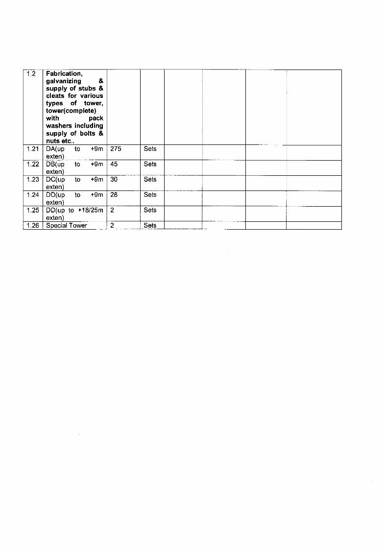
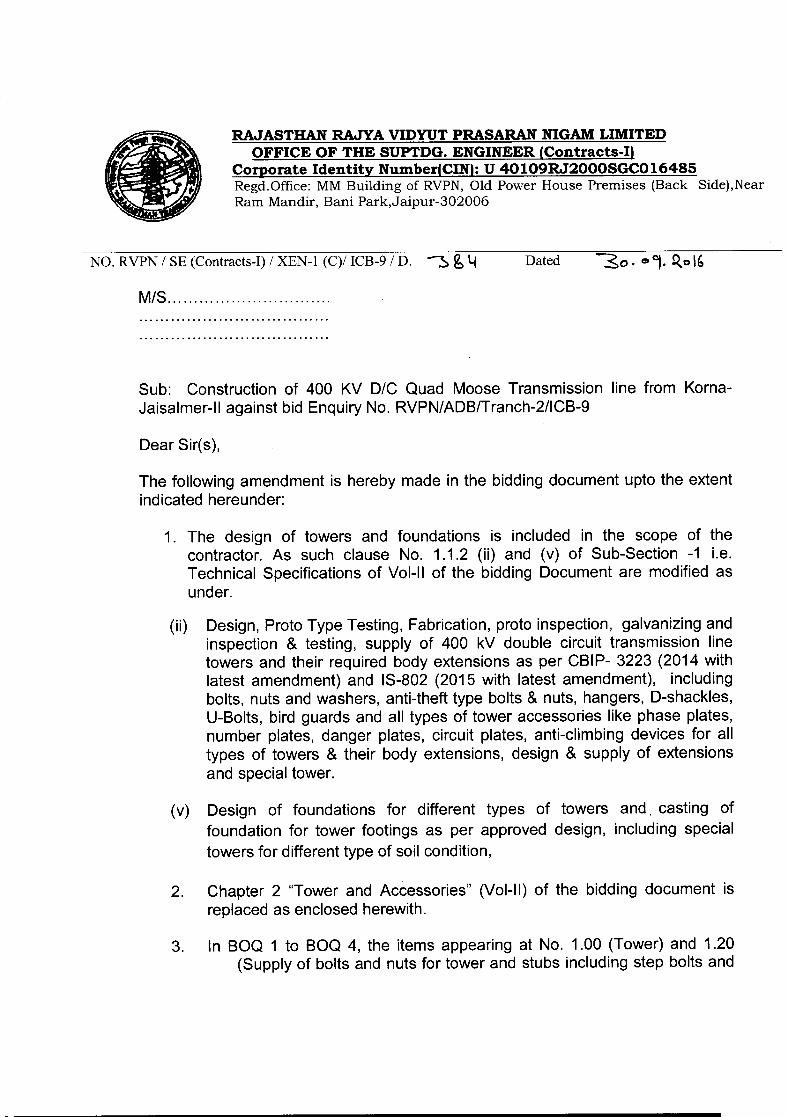
1.2 Fabrication,galvanizing &supply of stubs &cleats for varioustypes of tower,tower(complete)with packwashers includingsupply of bolts &nuts etc ..
1.21 DA(up to +9m 275 Setsexten)
1.22 DB(up to +9m 45 Setsextent
1.23 DC(up to +9m 30 Setsexten)
1.24 DD(up to +9m 28 Setsexten)
1.25 DD(up to +18/25m 2 Setsexten)
1.26 Special Tower 2 Sets

Annexure-II
Schedule BOQ 2- Supply- Plant & Equipment (including mandatory Spare Parts) Supplied from within,the Employer s countryS. Item Description Quantity Units Quoted EXW Taxes & Total Ex Total PriceNo. Currency unit Duties works
in INRI Price PriceOtherCurrency
Tower1.00 Fabrication,
galvanising andsupply of varioustypes of towers
(includingspecial towers),& its body 1 leg
(equal & unequal)extensions(complete)including
hangers, D-shackles, BirdGuard, U-Bolt,
Pack washer etc.
1.01 DA+OM 200 Sets1.02 DA+3M 35 Sets1.03 DA+6M 25 Sets1.04 DA+9M 15 Sets1.05 DB+OM 30 Sets1.06 DB+3M 7 Sets1.07 DB+6M 5 Sets1.08 DB+9M 3 Sets1.09 DC+OM 20 Sets1.10 DC+3M 5 Sets1.11 DC+6M 3 Sets1.12 DC+9M 2 Sets1.13 DD+OM 18 Sets1.14 DD+3M 4 Sets1.15 DD+6M 3 Sets1.16 DD+9M 3 Sets1.17 DD+18M 1 Sets1.18 DD+25M 1 Sets1.19 Special Tower 2 Sets
------------------------------------------------------------------------------------------------ -- ---- - - .
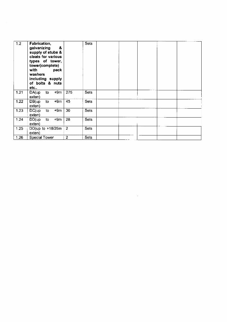
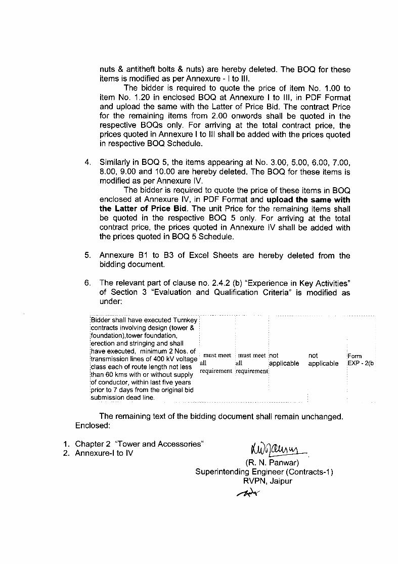
1.2 Fabrication, Setsgalvanizing &supply of stubs &cleats for varioustypes of tower,tower(complete)with packwashersincluding supplyof bolts & nutsetc ..
1.21 DA(up to +9m 275 Setsexten)
1.22 DB(up to +9m 45 Setsexten)
1.23 DC(up to +9m 30 Setsexten)
1.24 DD(up to +9m 28 Setsexten)
1.25 DD(up to +18/25m 2 Setsexten)
1.26 Special Tower 2 Sets
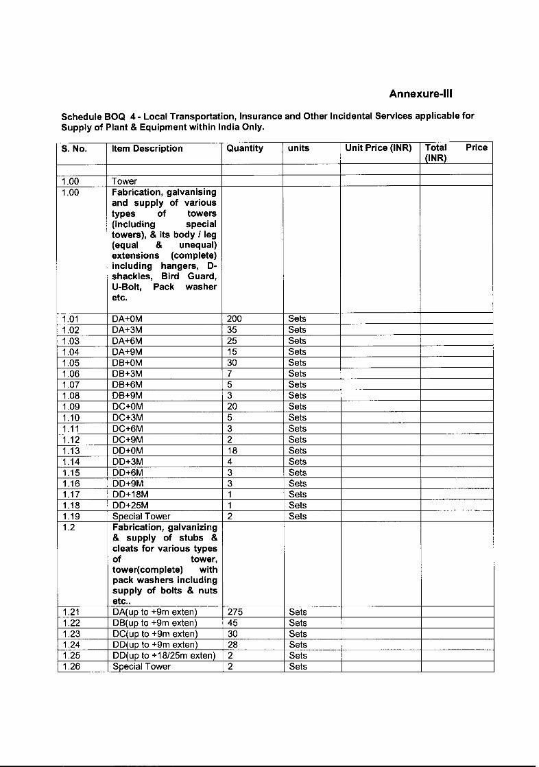
Annexure-III
Schedule BOQ 4 - Local Transportation, Insurance and Other Incidental Services applicable forSupply of Plant & Equipment within India Only.
S. No. Item Description Quantity units Unit Price (INR) Total Price(lNR)
1.00 Tower1.00 Fabrication, galvanising
and supply of varioustypes of towers(including specialtowers), & its body I leg(equal & unequal)extensions (complete)including hangers, D-shackles, Bird Guard,U-Bolt, Pack washeretc.
1.01 DA+OM 200 Sets1.02 DA+3M 35 Sets1.03 DA+6M 25 Sets1.04 DA+9M 15 Sets1.05 DB+OM 30 Sets1.06 DB+3M 7 Sets1.07 DB+6M 5 Sets1.08 DB+9M 3 Sets1.09 DC+OM 20 Sets1.10 DC+3M 5 Sets1.11 DC+6M 3 Sets1.12 DC+9M 2 Sets1.13 DD+OM 18 Sets1.14 DD+3M 4 Sets1.15 DD+6M 3 Sets1.16 DD+9M 3 Sets1.17 DD+18M 1 Sets1.18 DD+25M 1 Sets1.19 Special Tower 2 Sets1.2 Fabrication, galvanizing
& supply of stubs &cleats for various typesof tower,tower( com plete) withpack washers includingsupply of bolts & nutsetc ..
1.21 DA(up to +9m exten) 275 Sets1.22 DB(up to +9m exten) 45 Sets1.23 DC(up to +9m exten) 30 Sets1.24 DD(up to +9m exten) 28 Sets1.25 DD(up to +18/25m exten) 2 Sets1.26 Special Tower 2 Sets
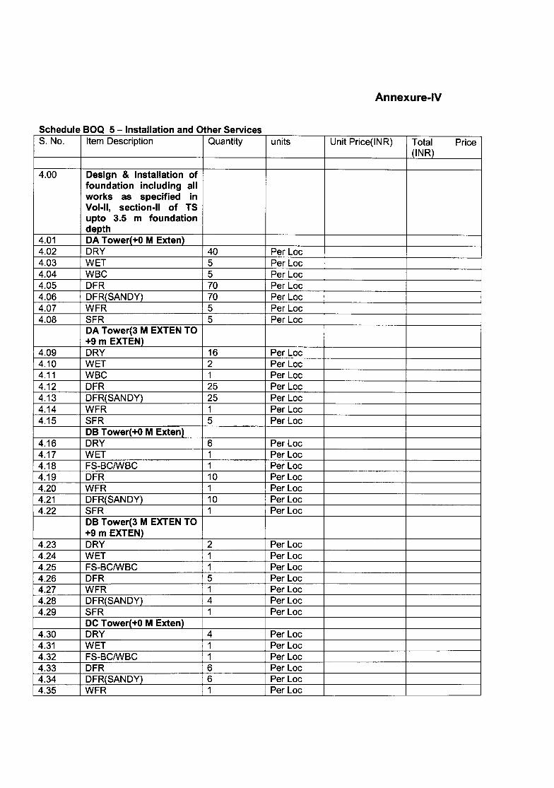
Annexure-IV
Schedule BOQ 5 -Installation and Other ServicesS. No. Item Description Quantity units Unit Price(INR) Total Price
(lNR)
4.00 Design & Installation offoundation including allworks as specified inVol-II. section-II of TSupto 3.5 m foundationdepth
4.01 DA Tower(+O M Exten)4.02 DRY 40 Per Loc4.03 WET 5 Per Loc4.04 WBC 5 PerLoc4.05 DFR 70 PerLoc4.06 DFR(SANDY) 70 Per Loc4.07 WFR 5 PerLoc4.08 SFR 5 Per Loc
DA Tower(3 M EXTEN TO+9 m EXTEN)
4.09 DRY 16 Per Loc4.10 WET 2 Per Loc4.11 WBC 1 Per Loc4.12 DFR 25 Per Loc4.13 DFR(SANDY) 25 Per Loc4.14 WFR 1 Per Loc4.15 SFR 5 PerLoc
DB Tower(+O M Exten)4.16 DRY 6 Per Loc4.17 WET 1 Per Loc4.18 FS-BCIWBC 1 Per Loc4.19 DFR 10 Per Loc4.20 WFR 1 Per Loc4.21 DFR(SANDY) 10 Per Loc4.22 SFR 1 Per Loc
DB Tower(3 M EXTEN TO+9 m EXTEN)
4.23 DRY 2 PerLoc4.24 WET 1 PerLoc4.25 FS-BCIWBC 1 PerLoc4.26 DFR 5 PerLoc4.27 WFR 1 PerLoc4.28 DFR(SANDY) 4 PerLoc4.29 SFR 1 PerLoc
DC Tower(+O M Exten)4.30 DRY 4 PerLoc4.31 WET 1 Per Loc4.32 FS-BCIWBC 1 PerLoc4.33 DFR 6 Per Loc4.34 DFR(SANDY) 6 Per Loc4.35 WFR 1 PerLoc
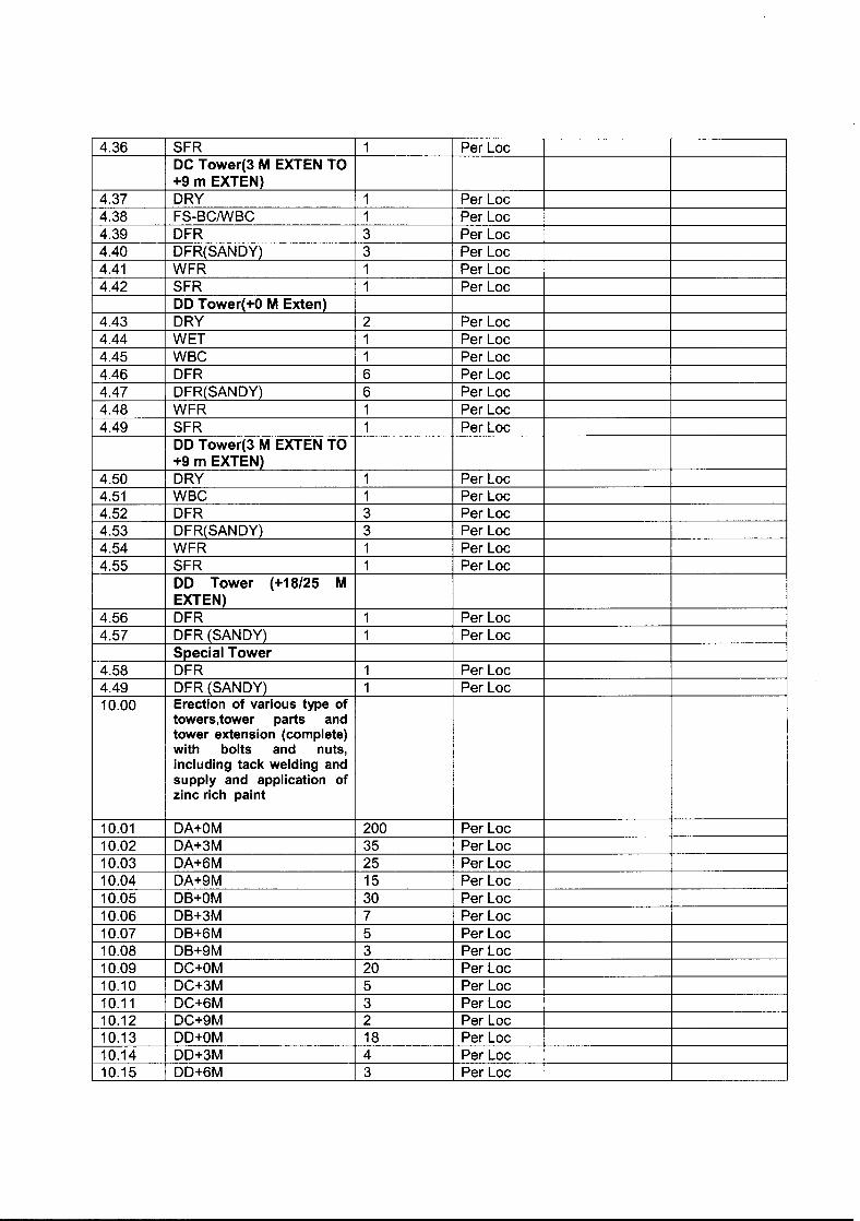
4.36 SFR 1 Per lacDC Tower(3 M EXTEN TO+9 m EXTEN)
4.37 DRY 1 Per lac4.38 FS-BCIWBC 1 Per lac4.39 DFR 3 Per lac4.40 DFR(SANDY) 3 Per lac4.41 WFR 1 Per lac4.42 SFR 1 Per lac
DD Tower(+O M Exten)4.43 DRY 2 Per lac4.44 WET 1 Per lac4.45 WBC 1 Per lac4.46 DFR 6 Per lac4.47 DFR(SANDY) 6 Per lac4.48 WFR 1 Per lac4.49 SFR 1 Per lac
DD Tower(3 M EXTEN TO+9 m EXTEN)
4.50 DRY 1 Per lac4.51 WBC 1 Per lac4.52 DFR 3 Per lac4.53 DFR(SANDY) 3 Per lac4.54 WFR 1 Per lac4.55 SFR 1 Per lac
DD Tower (+18/25 MEXTEN)
4.56 DFR 1 Per lac4.57 DFR (SANDY) 1 Per lac
Special Tower4.58 DFR 1 Per lac4.49 DFR (SANDY) 1 Per lac10.00 Erection of various type of
towers,tower parts andtower extension (complete)with bolts and nuts,including tack welding andsupply and application ofzinc rich paint
10.01 DA+OM 200 Per lac10.02 DA+3M 35 Per lac10.03 DA+6M 25 Per lac10.04 DA+9M 15 Per lac10.05 DB+OM 30 Per lac10.06 DB+3M 7 Per lac10.07 DB+6M 5 Per lac10.08 DB+9M 3 Per lac10.09 DC+OM 20 Per lac10.10 DC+3M 5 Per lac10.11 DC+6M 3 Per lac10.12 DC+9M 2 Per loc10.13 DD+OM 18 Per lac10.14 DD+3M 4 Per lac10.15 DD+6M 3 Per lac
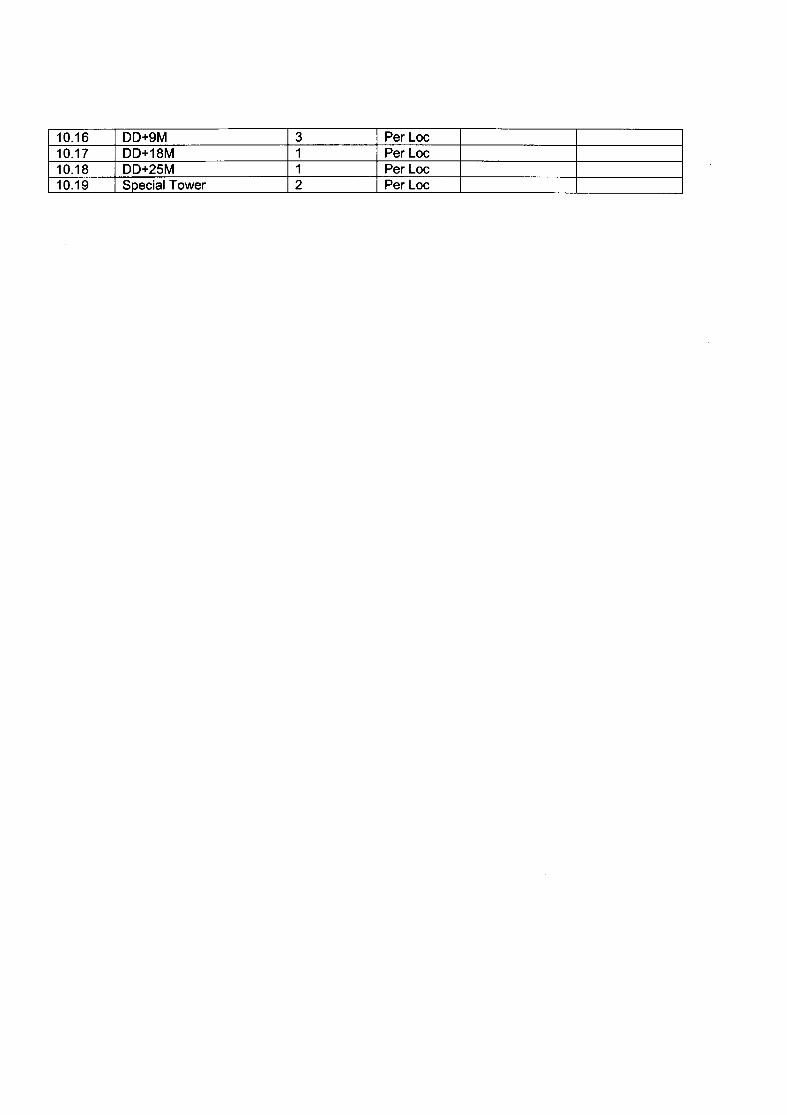
10.16 DD+9M 3 Per Lac10.17 DD+18M 1 Per Lac10.18 DD+2SM 1 Per Lac10.19 Special Tower 2 Per Lac
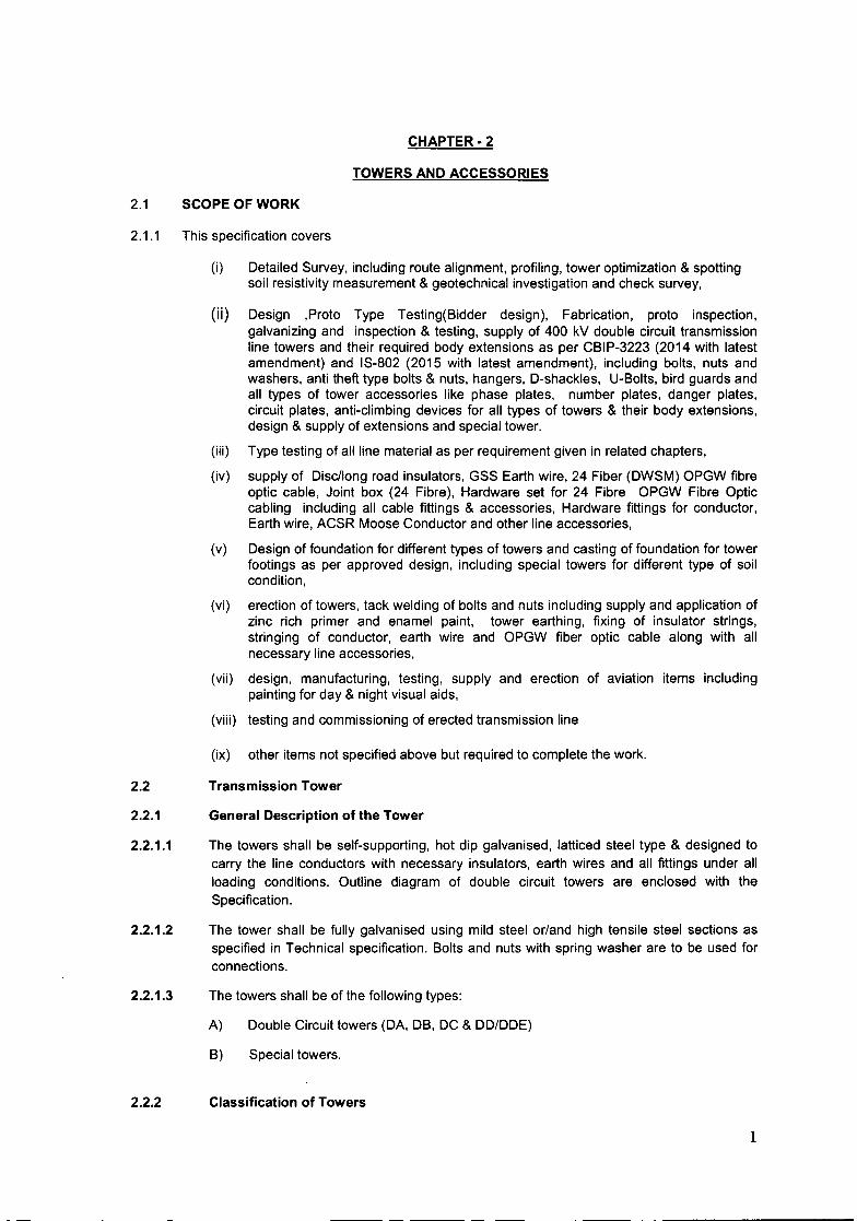
CHAPTER· 2
2.1 SCOPE OF WORK
TOWERS AND ACCESSORIES
2.1.1 This specification covers
2.2
2.2.1
2.2.1.1
2.2.1.2
2.2.1.3
(I) Detailed Survey, including route alignment, profiling, tower optimization & spottingsoil resistivity measurement & geotechnical investigation and check survey,
(ii) Design ,Proto Type Testing(Bidder design), Fabrication, proto inspection,galvanizing and inspection & testing, supply of 400 kV double circuit transmissionline towers and their required body extensions as per CBIP-3223 (2014 with latestamendment) and IS-802 (2015 with latest amendment), including bolts, nuts andwashers, anti theft type bolts & nuts, hangers, D-shackles, U-Bolts, bird guards andall types of tower accessories like phase plates, number plates, danger plates,circuit plates, anti-climbing devices for all types of towers & their body extensions,design & supply of extensions and special tower.
(iii) Type testing of all line material as per requirement given in related chapters,
(iv) supply of Disc/long road insulators, GSS Earth wire, 24 Fiber (DWSM) OPGW fibreoptic cable, Joint box (24 Fibre), Hardware set for 24 Fibre OPGW Fibre Opticcabling including all cable fittings & accessories, Hardware fittings for conductor,Earth wire, ACSR Moose Conductor and other line accessories,
(v) Design of foundation for different types of towers and casting of foundation for towerfootings as per approved design, including special towers for different type of soilcondition,
(vi) erection of towers, tack welding of bolts and nuts including supply and application ofzinc rich primer and enamel paint, tower earthing, fixing of insulator strings,stringing of conductor, earth wire and OPGW fiber optic cable along with allnecessary line accessories,
(vii) design, manufacturing, testing, supply and erection of aviation items includingpainting for day & night visual aids,
(viii) testing and commissioning of erected transmission line
(ix) other items not specified above but required to complete the work.
Transmission Tower
General Description of the Tower
The towers shall be self-supporting, hot dip galvanised, latticed steel type & designed tocarry the line conductors with necessary insulators, earth wires and all fittings under allloading conditions. Outline diagram of double circuit towers are enclosed with theSpecification.
The tower shall be fully galvanised using mild steel or/and high tensile steel sections asspecified in Technical specification. Bolts and nuts with spring washer are to be used forconnections.
The towers shall be of the following types:
A) Double Circuit towers (DA, DB, DC & DD/DDE)
B) Special towers.
2.2.2 Classification of Towers
1
---- --
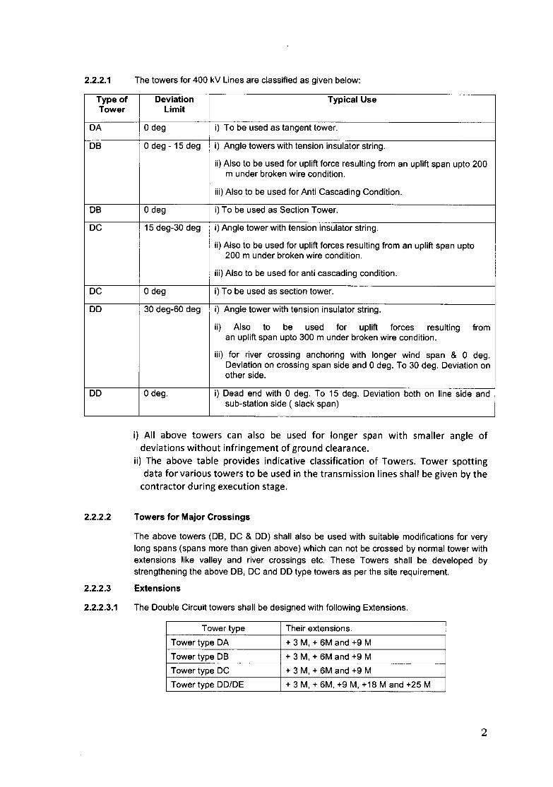
2.2.2.1 The towers for 400 kV Lines are classified as given below:
Type of Deviation Typical UseTower Limit
DA o deg i) To be used as tangent tower.
DB o deg - 15 deg i) Angle towers with tension insulator string.
ii) Also to be used for uplift force resulting from an uplift span upto 200m under broken wire condition.
iii) Also to be used for Anti Cascading Condition.
DB o deg i) To be used as Section Tower.
DC 15 deg-30 deg i) Angle tower with tension insulator string.
ii) Also to be used for uplift forces resulting from an uplift span upto200 m under broken wire condition.
iii) Also to be used for anti cascading condition.
DC o deg i) To be used as section tower.
DD 30 deg-60 deg i) Angle tower with tension insulator string.
ii) Also to be used for uplift forces resulting froman uplift span upto 300 m under broken wire condition.
iii) for river crossing anchoring with longer wind span & 0 deg.Deviation on crossing span side and 0 deg. To 30 deg. Deviation onother side.
DD o deg. i) Dead end with 0 deg. To 15 deg. Deviation both on line side andsub-station side ( slack span)
i) All above towers can also be used for longer span with smaller angle ofdeviations without infringement of ground clearance.
ii) The above table provides indicative classification of Towers. Tower spottingdata for various towers to be used in the transmission lines shall be given by thecontractor during execution stage.
2.2.2.2 Towers for Major Crossings
2.2.2.3
The above towers (DB, DC & DD) shall also be used with suitable modifications for verylong spans (spans more than given above) which can not be crossed by normal tower withextensions like valley and river crossings etc. These Towers shall be developed bystrengthening the above DB, DC and DD type towers as per the site requirement.
Extensions
2.2.2.3.1 The Double Circuit towers shall be designed with following Extensions.
Tower type Their extensions.Tower type DA + 3 M, + 6M and +9 MTower type DB + 3 M, + 6M and +9 MTower type DC + 3 M, + 6M and +9 MTower type DD/DE + 3 M, + 6M, +9 M, +18 M and +25 M
2
2.2.2.3.2 The provision for addition of +18/+25M body extension to tower types DA and DD is also tobe kept. For Power Line Crossing or any other obstacle, tower types DA and DD can beused with 18/25 M extensions depending, upon the merit of the prevailing site condition.The maximum reduced spans for DA, DB, DC and DD type towers shall be mentioned inthe tower spotting data prepared by contractor based on design. However this shall, in nocase be less than 250 meters.
2.2.2.3.3 The towers shall be designed for providing unequal leg extensions with maximumdifference between the shortest and the longest leg of 3M for DB, DC, and DD towers.These unequal leg extensions to be provided in the design shall be used during towerspotting / execution stage to optimize the benching / revetment requirement.
2.2.2.3.4 In situations where difference in leg differential does not suit the standard unequal legextension provisions on the towers mentioned above, suitable chimney extensions shall beprovided to reduce benching/revetment requirement.
2.2.2.3.5 The leg extensions, unequal leg extensions, chimney extensions and / or a combination ofthese suitable for a tower location shall be selected on the basis of techno-economicsevaluation.
2.2.2.3.6 All above body / leg extension provisions to towers shall be treated as part of normal toweronly.
2.2.2.3.7 The payment for leg extensions and any additional structure shall be paid on pro rata basisderived from the quoted price and final approved weight of DA+OMTower.
2.2.3 Spans
2.2.3.1 Design Span or Normal Span
The Design Span or Normal Ruling Span of the line is 400m for 400 KV transmission line.
2.2.3.2 Wind Span
The wind span is the sum of the two half spans adjacent to the tower under consideration.For normal horizontal spans this equals to normal ruling span.
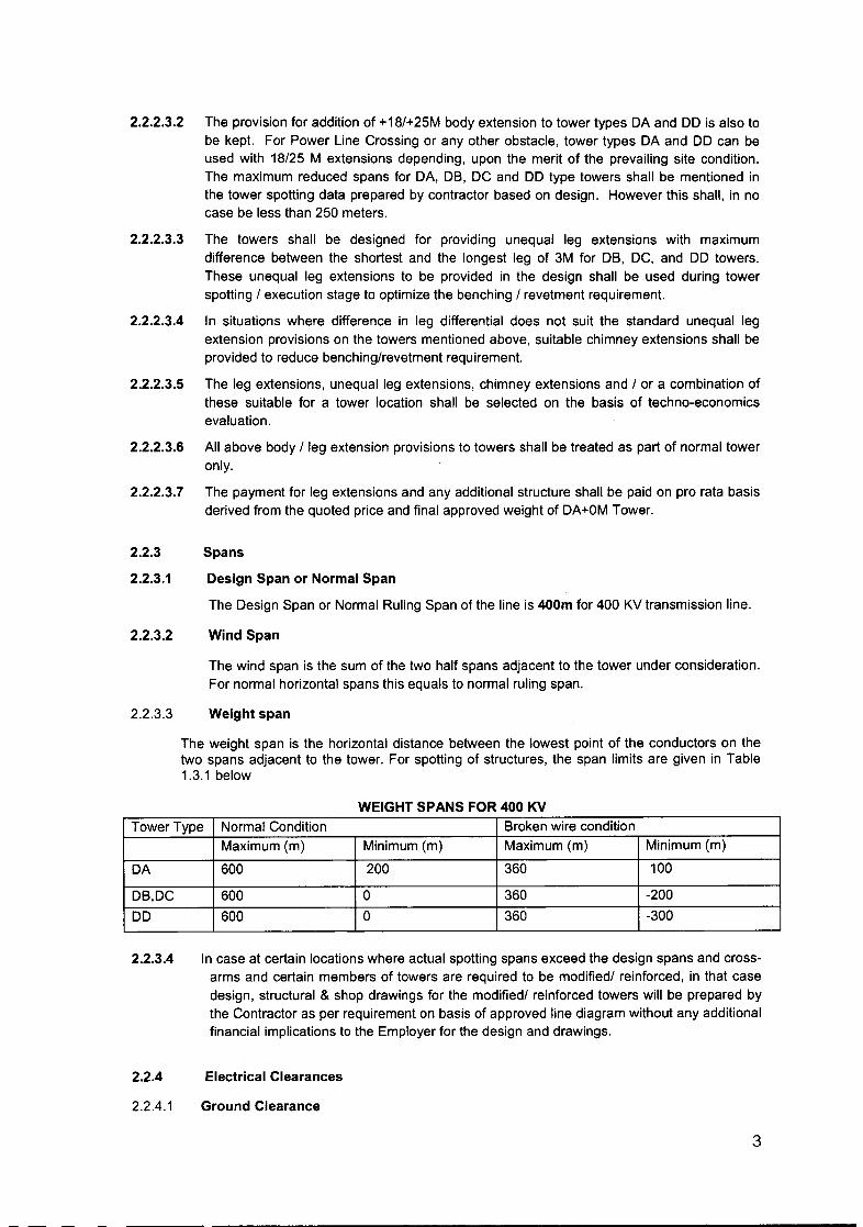
2.2.3.3 Weight span
The weight span is the horizontal distance between the lowest point of the conductors on thetwo spans adjacent to the tower. For spotting of structures, the span limits are given in Table1.3.1 below
WEIGHT SPANS FOR 400 KVTower Type Normal Condition Broken wire condition
Maximum (rn) Minimum (rn) Maximum (m) Minimum (rn)
DA 600 200 360 100
DB,DC 600 0 360 -200DD 600 0 360 -300
2.2.3.4 In case at certain locations where actual spotting spans exceed the design spans and crossarms and certain members of towers are required to be modified/ reinforced, in that casedesign, structural & shop drawings for the modified/ reinforced towers will be prepared bythe Contractor as per requirement on basis of approved line diagram without any additionalfinancial implications to the Employer for the design and drawings.
2.2.4
2.2.4.1
Electrical Clearances
Ground Clearance
3

2.2.4.2
2.2.4.3
2.2.4.4
2.2.4.5
2.2.4.6
The minimum ground clearance from the bottom conductor shall not be less than 8840 mmfor 400 kV at the maximum sag conditions i.e at 85°C and still air.
a) An allowance of 150mm shall be provided to account for errors in stringing.
b) Conductor creep shall be compensated by over tensioning the conductor at atemperature of 26°C, lower than the stringing temperature for ACSR "MOOSE" for400 kV transmission lines.
Power Line Crossing
Minimum clearance between power lines to power line crossing in metres should be asfollows
51. No. Nominal System Voltage 110-132KV 220KV 400KV 765KV1. 110-132KV 3.05
4.58
5.49
4.58 5.49
5.49
5.49
7.94
2. 220KV
400KV
765KV
4.58
5.49
7.94
3. 7.94
7.944. 7.94 7.94 7.94
Live Metal Clearance
The minimum live metal clearance to be provided between the live parts and steel work ofsuperstructure shall be as given in Table 1.2.
TABLE-1.2400 KV
For Single Suspension Insulator Strings1. 0°-22° Swing 3050 mm2. 22°-44° Swing 1860 mmFor Jumpers in tension insulator strings
1. 0°-20° Swing 3050 mm
The pilot insulator strings are to be used for DO/DE towers only.
The bidder is permitted to adopt separate cross arm for 'DO' type towers under dead endconditions provided adequate live metal clearance is available with at least 15° angle onboth line side and slack span side, and also provided that all the specified conditions ofthe specifications are fulfilled.
Bidder shall adopt same cross arm design where jumper is projecting outside of cross-armfor DO type tower, used as dead end and angle tower.
For computing the live metal clearances the dimensions of, Double Suspension, SingleSuspension Pilot, Single Tension and Quad tension, strings shall be taken as given inenclosed drawings. The design of the tower shall be such that it should satisfy all theabove conditions when clearances are measured from any live point of the strings.
Cross arm projections for Dead end towers shall be fixed in such a way that it canaccommodate a condition of 15 degree deviation of conductors towards tower at both Leftand Right side cross arms on slack span side and 0-15 degrees deviation on line side.
4
2.2.4.7 Angle of Shielding
The angle of shielding is defined as the angle formed by the line joining the centre lines ofthe earthwire/OPGW and outer power conductor in still air at tower supports, to the verticalline through the centre line of the earthwire. Bidders shall design the tower in such a waythat the angle of shielding does not exceed 20° for 400 KV. The drop of the earthwireclamp equal to 150 mm should be considered while calculating the minimum angle ofprotection.
2.2.4.8 Mid Span Clearance
The minimum vertical mid span clearance between the earthwire and the nearest powerconductor shall not be less than 9000 mm for 400 KV, which shall mean the verticalclearance between earthwire and the nearest conductor under all temperatures and still aircondition in the normal ruling span. Further, the tensions of the eathwire/ OPGW andpower conductor, shall be so co-ordinated that the sag of earthwire shall be at least 10%less than that of power conductors under all temperature loading conditions.
2.2.5 Tower Loading Conditions:
The design of towers shall be carried out by the Contractor as per IS 802 (Part 1/section-1) 2015 considering wind zone 4.
b) Terrain category shall be considered as 2c) Reliability level shall be considered as 1 for 400 kV lines.
2.2.5.1 Design Temperatures
The following temperature range for the conductors and ground wires shall be adopted forline design:
i) Minimum Temperature o deg.C
32 deg.Cii) Every day temperature of conductor
iii) Max. temperature of
a) Conductor
b) Earthwire exposed to sun
85 deg.C
53 deg.C
2.2.5.2 Phase Configuration
For double circuit towers the three phases shall be in vertical formation. The phase tophase spacing for conductors shall be not less than 8000 mm for 400 kV vertically.
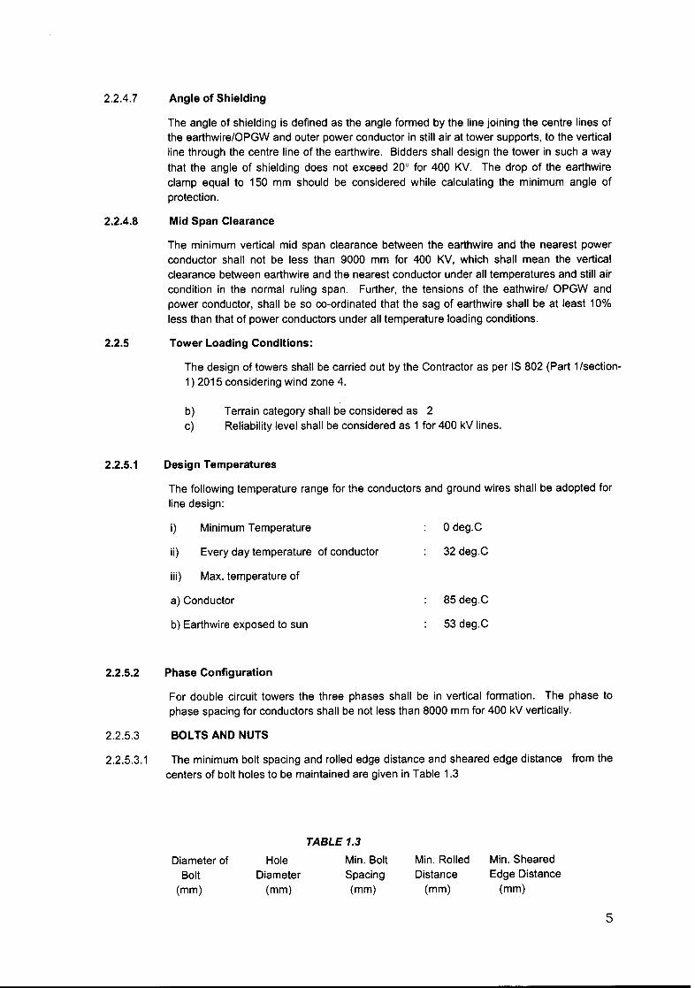
2.2.5.3 BOLTS AND NUTS
2.2.5.3.1 The minimum bolt spacing and rolled edge distance and sheared edge distance from thecenters of bolt holes to be maintained are given in Table 1.3
Diameter ofBolt
(mm)
HoleDiameter(mm)
TABLE 1.3
Min. BoltSpacing(mm)
Min. RolledDistance(mm)
Min. ShearedEdge Distance(mm)
5
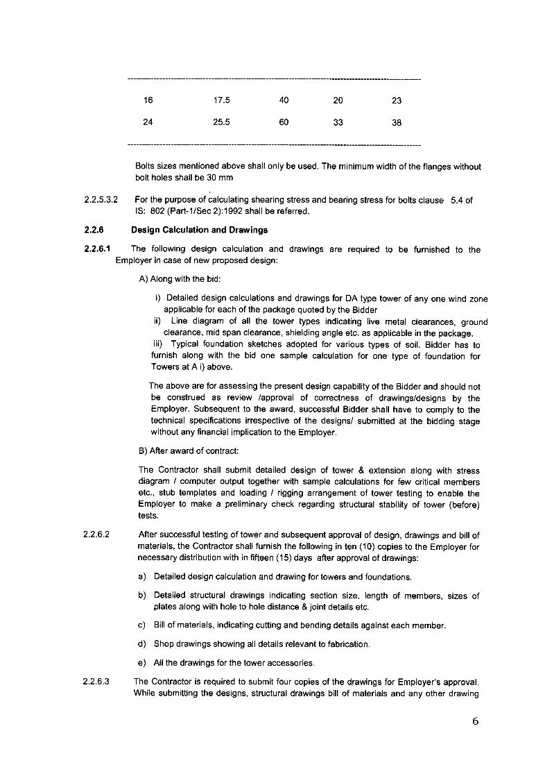
16 17.5 40 20 23
24 25.5 60 33 38
Bolts sizes mentioned above shall only be used. The minimum width of the flanges withoutbolt holes shall be 30 mm
2.2.5.3.2 For the purpose of calculating shearing stress and bearing stress for bolts clause 5.4 ofIS: 802 (Part-1/Sec 2):1992 shall be referred.
2.2.6 Design Calculation and Drawings
2.2.6.1 The following design calculation and drawings are required to be furnished to theEmployer in case of new proposed design:
A) Along with the bid:
i) Detailed design calculations and drawings for DA type tower of anyone wind zoneapplicable for each of the package quoted by the Bidder
ii) Line diagram of all the tower types indicating live metal clearances, groundclearance, mid span clearance, shielding angle etc. as applicable in the package.
iii) Typical foundation sketches adopted for various types of soil. Bidder has tofurnish along with the bid one sample calculation for one type of foundation forTowers at A i) above.
The above are for assessing the present design capability of the Bidder and should notbe construed as review /approval of correctness of drawings/designs by theEmployer. Subsequent to the award, successful Bidder shall have to comply to thetechnical specifications irrespective of the designs/ submitted at the bidding stagewithout any financial implication to the Employer.
B) After award of contract:
The Contractor shall submit detailed design of tower & extension along with stressdiagram / computer output together with sample calculations for few critical membersetc., stub templates and loading / rigging arrangement of tower testing to enable theEmployer to make a preliminary check regarding structural stability of tower (before)tests.
2.2.6.2 After successful testing of tower and subsequent approval of design, drawings and bill ofmaterials, the Contractor shall furnish the following in ten (10) copies to the Employer fornecessary distribution with in fifteen (15) days after approval of drawings:
a) Detailed design calculation and drawing for towers and foundations.
b) Detailed structural drawings indicating section size, length of members, sizes ofplates along with hole to hole distance & joint details etc.
2.2.6.3
c) Bill of materials, indicating cutting and bending details against each member.
d) Shop drawings showing all details relevant to fabrication.
e) All the drawings for the tower accessories.
The Contractor is required to submit four copies of the drawings for Employer's approval.While submitting the designs, structural drawings bill of materials and any other drawing
6
2.2.6.4
2.2.6.5
2.2.6.6
2.2.6.7
pertaining to the subject transmission line, the Contractor shall clearly indicate on eachdrawing Specification No., Name of the transmission line and project, letter reference No.and date on which the submission are made. The same practice is also to be followedwhile submitting distribution copies.
The design and drawings as covered in clause above shall be approved / commented bythe Employer as the case may be within twenty eight (28) days of receipt of design /drawings in Employer office. If the design / drawings are commented by the Employer, theContractor shall submit revised designs / drawings with in fifteen (15) days of date of issueof comments.
The Contractor is required to furnish the progress of submissions and approvals of designsand drawings on twenty fifth day of every month till the completion of all the designactivities ..
The details shall include description of design / drawing, schedule date of submission,actual date of submission schedule date of approval ,actual date of approval, scheduledate of submission of distribution copies, actual date of submission of distribution copies,schedule date of tower test, actual date of tower test and 'Remarks' column. Provision ofsix additional columns shall also be made in the above progress report to indicate date ofcomments issued by the Employer and details of submission of revised designs /drawings.
The tower accessories drawings like name plate, danger plate, phase plate, circuit plate,anticlimbing device, step bolt, D-shackle etc. shall also be prepared by the Contractor andshall be submitted to the Employer, in three copies, along with one reproducible, forrecord. These drawings shall be prepared in A4 size only.
All the drawings shall have a proper name plate clearly displaying the name of Employer onright hand bottom corner. The approval for exact format of the nameplate shall be obtainedby the successful bidder from the Employer for adopting the same on all the drawings. Alsoall the drawings shall carry the following statement and shall be displayed conspicuously onthe drawing:
WARNING: THIS IS PROPRIETORY ITEM AND DESIGN RIGHT IS STRICTLY RESERVED WITHEMPLOYER. UNDER NO CIRCUMSTANCES THIS DRAWING SHALL BE USED BY ANYBODYWITHOUT PRIOR PERMISSION FROM NEA IN WRITING.
2.2.7. Joints shall be so designed so as to avoid eccentricity. The use of gusset plates for jointingtower member shall be avoided as far as possible. However, where connections are suchthat the elimination of the gusset plates would result in eccentric joints then gussets platesand spacer plates may be used in conformity with modern practices. The thickness of thegusset plate, required to transmit stress, shall not be less than that of the thinnest ofconnected member but not less than 5 mm in any case.
2.2.8 TOWER STEEL SECTIONS
2.2.8.1 Steel Sections for towers to be used in towers, extensions, special towers, stubs and stubsetting templates shall be of tested quality conforming to IS-2062: 2006 of grade E 250 & yieldstrength 2550 kg/cm2 for mild steel and IS-2062: 2006 of grade E 350/BSEN 10025 grade 355JR & yield strength 3565 kg/cm2 for high tensile steel.
2.2.8.3 THICKNESS OF MEMBERS
7
The minimum thickness of angle sections used in the design of towers shall not be less thanthe following values:
(a) Leg members and all members of cross- arm. - 5 mm(b) For all other members. - 4 mm
2.2.8.4 PERMISSIBLE STRESSES
2.2.8.5 AXIAL STRESS IN TENSION
The estimated tensile stresses on the net effective sectional area in various membersmultiplied by appropriate factor of safety shall not exceed minimum guaranteed yield stress ofthe material.
2.2.8.6 AXIAL STRESS IN COMPRESSION
Axial stresses in compression in various members shall be computed in accordance withClause NO.9.2of IS 802 (Part-I) .
2.2.8.7 STRESS IN BOLTS
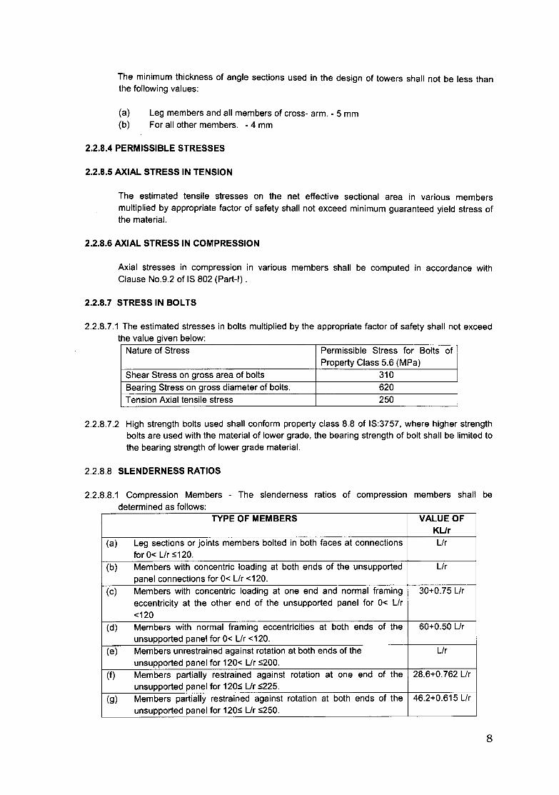
2.2.8.7.1 The estimated stresses in bolts multiplied by the appropriate factor of safety shall not exceedthe value given below:Nature of Stress Permissible Stress for Bolts of
Property Class 5.6 (MPa)Shear Stress on gross area of bolts 310Bearing Stress on gross diameter of bolts. 620Tension Axial tensile stress 250
2.2.8.7.2 High strength bolts used shall conform property class 8.8 of IS:3757, where higher strengthbolts are used with the material of lower grade, the bearing strength of bolt shall be limited tothe bearing strength of lower grade material.
2.2.8.8 SLENDERNESS RATIOS
2.2.8.8.1 Compression Members - The slenderness ratios of compression members shall bedetermined as follows:
TYPE OF MEMBERS VALUE OFKLlr
(a) Leg sections or joints members bolted in both faces at connections Llrfor 0< Llr S120.
(b) Members with concentric loading at both ends of the unsupported Llrpanel connections for 0< Llr <120.
(c) Members with concentric loading at one end and normal framing 30+0.75 Llreccentricity at the other end of the unsupported panel for 0< Llr<120
(d) Members with normal framing eccentricities at both ends of the 60+0.50 Llrunsupported panel for 0< Llr <120.
(e) Members unrestrained against rotation at both ends of the Llrunsupported panel for 120< Llr S200.
(f) Members partially restrained against rotation at one end of the 28.6+0.762 Llrunsupported panel for 120S Ur S225.
(g) Members partially restrained against rotation at both ends of the 46.2+0.615 Llrunsupported panel for 120S Ur S250.
8
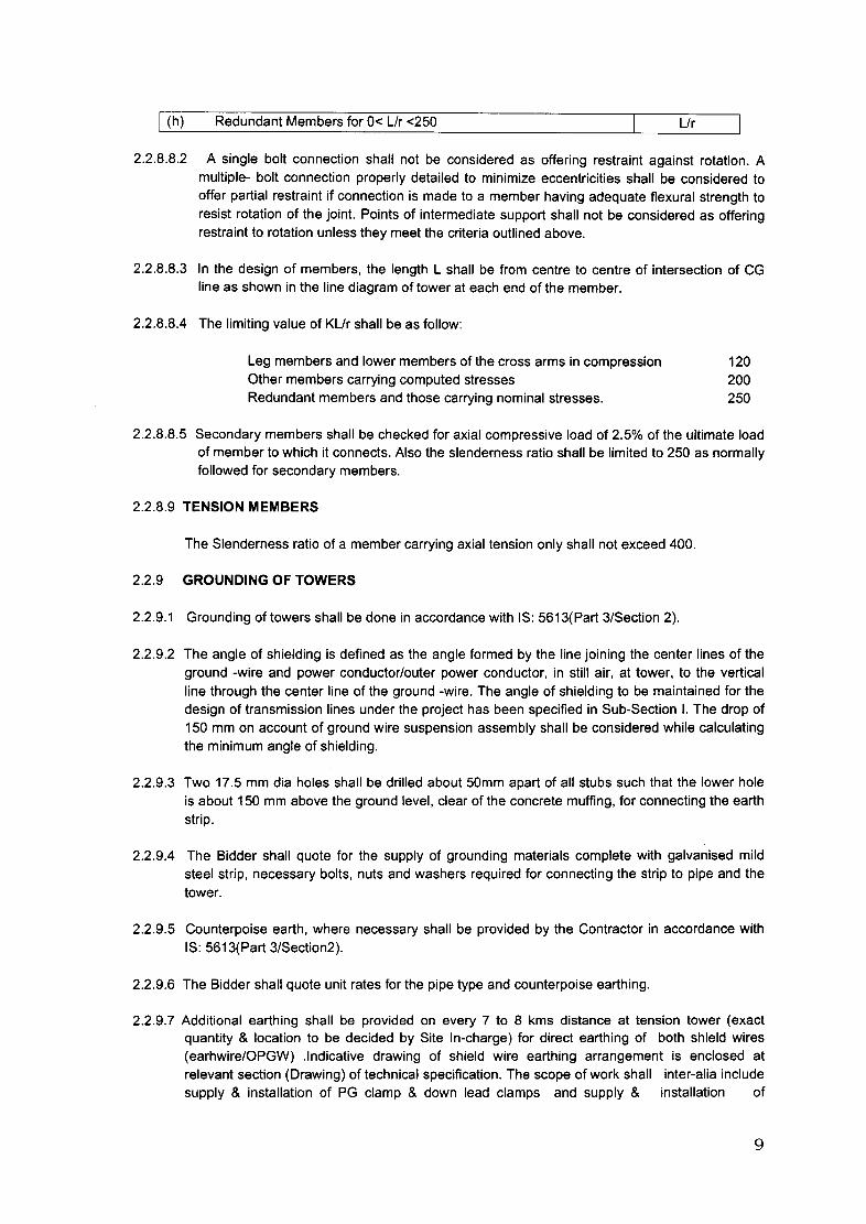
I (h) Redundant Members for 0< Llr <250 Lir
2.2.8.8.2 A single bolt connection shall not be considered as offering restraint against rotation. Amultiple- bolt connection properly detailed to minimize eccentricities shall be considered tooffer partial restraint if connection is made to a member having adequate flexural strength toresist rotation of the joint. Points of intermediate support shall not be considered as offeringrestraint to rotation unless they meet the criteria outlined above.
2.2.8.8.3 In the design of members, the length L shall be from centre to centre of intersection of CGline as shown in the line diagram of tower at each end of the member.
2.2.8.8.4 The limiting value of KLlr shall be as follow:
Leg members and lower members of the cross arms in compressionOther members carrying computed stressesRedundant members and those carrying nominal stresses.
120200250
2.2.8.8.5 Secondary members shall be checked for axial compressive load of 2.5% of the ultimate loadof member to which it connects. Also the slenderness ratio shall be limited to 250 as normallyfollowed for secondary members.
2.2.8.9 TENSION MEMBERS
The Slenderness ratio of a member carrying axial tension only shall not exceed 400.
2.2.9 GROUNDING OF TOWERS
2.2.9.1 Grounding of towers shall be done in accordance with IS: 5613(Part 3/Section 2).
2.2.9.2 The angle of shielding is defined as the angle formed by the line joining the center lines of theground -wire and power conductor/outer power conductor, in still air, at tower, to the verticalline through the center line of the ground -wire. The angle of shielding to be maintained for thedesign of transmission lines under the project has been specified in Sub-Section I. The drop of150 mm on account of ground wire suspension assembly shall be considered while calculatingthe minimum angle of shielding.
2.2.9.3 Two 17.5 mm dia holes shall be drilled about 50mm apart of all stubs such that the lower holeis about 150 mm above the ground level, clear of the concrete muffing, for connecting the earthstrip.
2.2.9.4 The Bidder shall quote for the supply of grounding materials complete with galvanised mildsteel strip, necessary bolts, nuts and washers required for connecting the strip to pipe and thetower.
2.2.9.5 Counterpoise earth, where necessary shall be provided by the Contractor in accordance withIS: 5613(Part 3/Section2).
2.2.9.6 The Bidder shall quote unit rates for the pipe type and counterpoise earthing.
2.2.9.7 Additional earthing shall be provided on every 7 to 8 kms distance at tension tower (exactquantity & location to be decided by Site In-charge) for direct earthing of both shield wires(earhwire/OPGW) .Indicative drawing of shield wire earthing arrangement is enclosed atrelevant section (Drawing) of technical specification. The scope of work shall inter-alia includesupply & installation of PG clamp & down lead clamps and supply & installation of
9
additional earthing (pipe type or counter poise type) depending upon soil resistivity. Additionalearthwire bits required for down leads connecting shield wires with the earthing shall be eithersupplied by Owner separetly (as Owner supplied material) or shall be supplied by contractor(payable as per unit rate of GS Earthwire under the contract),as may be decided by Site Incharge
2.2.10 STEP BOLTS AND LADDERS
Two of the diagonally opposite legs shall be provided with step-bolts which shall conform to theprovisions of IS: 5613 (Part 3/Section 2). Each step bolt shall be provided with two nuts on oneend and a button head at the other to prevent slipping of feet. The step-bolts shall be capableof withstanding a vertical load of not less than 150 kg. assumed as a distributed load actingover 175 mm length of the bolt from the button head end. Each tower shall be provided withstep bolts conforming to 15:10238 of not less than 16 mm dia., 50 mm head and 175 mm long,spaced about 3.0 mtr. above the ground level to the top of the tower.
2.2.10.2 In the case of special structures, if the height of superstructure exceeds 60 metres,ladder alongwith protection rings of approved design shall be provided in continuation of thestep-bolts on the longitudinal face of the tower. from 60 metres above ground level to the topof the special structure. Suitable platforms using flats and chequered plates not less than 6mmthick alongwith suitable railing for access from step-bolts to the ladder and from the ladder toeach cross-arm and the ground wire support shall also be provided.
2.2.11 NUMBER PLATES, DANGER PLATES, CIRCUIT PLATES & PHASE PLATES AND BIRDGUARD
a) Each tower shall be fitted with a number plate, phase plate, circuit plates & danger plate.All towers should have the provision of fixing these accessories on the transverse face.The arrangement for fixing these accessories shall not be more than 4.5 m above theground level.
b) The letters, figures and the conventional skull and bones of danger plates shall conformto IS: 2551 and shall be in a signal red on the front of the plate.
c) The corners of the number and danger plate shall be rounded off to remove sharpedges.
d) The letters of number and circuit plates shall be red enameled with white enameledbackground.
f) Six Nos. Saw tooth type bird guards should be provided for each tower type DA,conforming to IS: 5613 (part-2, Sec-1).
2.2.12 ANTI·CLlMBING DEVICE
2.2.12.1 Towers shall be fitted with anti-climbing devices of spike type and conform to IS: 5613 (Part3/Section 1). The height of the anti-climbing device shall be provided approximately 2.5 to 3.5meter above ground level.
2.2.12.2 Necessary holes shall be provided on the tower members for installation of the anti-climbingdevice.
2.2.12.3 The Bidder shall quote unit rate for anti- climbing device inclusive of structure and bolts andnuts.
10
2.2.13 Quantities and weights
2.2.13.1 The provisional quantity of towers & extensions are mentioned in the respective Schedule ofPrices. Final quantities shall be determined after completion and approval of the tower spotting& check survey. The final quantities of tower shall be confirmed by the Employer based on therequired quantities of various towers & extensions furnished by the Contractor after completionof final tower spotting & check survey. Hence, it will be responsibility of the Contractor tointimate the exact requirements of all towers and various line materials required for lineimmediately after the tower spotting & check survey.
2.2.13.2 The Employer reserves the right to order the final quantities including reasonable quantities ofspares for which the rates quoted in the Bid shall be valid. Regarding quantity variation, theprovisions of relevant clauses of SCC shall apply.
2.2.13.3 The weight of tower shall mean the weight of tower calculated by using the black sectional (i.e.un galvanized) weight of steel members of the size indicated in the approved fabricationdrawings and bill of materials, without taking into consideration the reduction in weights due toholes, notches and bevel cuts etc. but taking into consideration the weight of the anticlimbingdevices, 0 shackles, hangers, strain plates, pack plates, gusset plates and pack washers etc.The weight of gusset plates shall mean the weight of its circumscribing rectangle, withouttaking into consideration the reduction in weights due to holes, notches etc.. For bolts andnuts along with spring washers and step bolts, the weight per tower shall be calculated fromthe bolt schedule applicable to each type of towers, stubs and leg extensions as approved bythe Employer. The rate quoted by the bidder for supply of tower / tower parts is deemed to beinclusive of galvanizing charges including the cost of zinc.
2.2.13.4 The weights of double circuit towers and their extensions (to be provided by bidder) are to begiven in Schedules and the same shall be treated as ceiling weights for payment purposes.However, the weight of each type of tower extensions (to be designed by the bidder) shall alsobe given by the bidder, if required in the Schedules of Prices and the same shall be treated asthe ceiling weight for payment purposes.
2.2.14 Galvanizing
2.2.14.1 Fabricated Tower Parts & Stubs
The tower parts, stubs and pack washers shall be hot dip galvanized .The galvanization shallbe done as per requirements of IS: 4759 after all fabrication work is completed. Thecontractor shall also take guidelines from the recommended practices for hot dip galvanizinglaid down in IS 2629 while deciding and implementing galvanizing procedure. The mandatoryrequirements however, are specified herein.
Unless otherwise specified the fabricated tower parts and stubs shall have a minimum overallZinc coating of 610 gms per sq. m of surface except for plates below 5mm which shall haveZinc coating of 460 gms per sq. m of surface. The average zinc coating for sections 5mm &above shall be maintained as 87 microns and that for sections below 5mm shall bemaintained as 65 microns.
The zinc coating shall be adherent, reasonably uniform, smooth, continuous and free fromimperfections such as black bare spots, ash rust stains, bulky white deposits / wet storagestains and blisters.
The surface preparation for fabricated tower parts and stubs for hot dip galvanizing shall becarried out as indicated herein below:
11
(i) Degreasing & Cleaning of Surface: Degreasing and cleaning of surface, whereverrequired, shall be carried out in accordance with clause 4.1 of IS 2629-1985. Afterdegreasing the article shall be thoroughly rinsed. However, if acidic degreasers are usedrinsing is not required.
(ii) Pickling: Pickling shall be done using either hydrochloric or sulfuric acid asrecommended at clause 4.3 of IS 2629 -1985. The actual concentration of the acids andthe time duration of immersion shall be determined by the Contractor depending on thenature of material to be pickled. Suitable inhibitors also shall be used with the acids toavoid over pickling. The acid concentration, inhibitors used, and maximum allowable ironcontent shall form part of plant standard to be formulated and submitted to Purchaseralong with Quality Assurance Program.
(iii) Rinsing: After pickling, the material shall be rinsed, preferably in running water to removeacid traces, iron particles or any other impurities from the surface. Two rinse tanks arepreferable, with water cascading from the second tank to the first to ensure thoroughcleaning. Wherever single tank is employed, the water shall be periodically changed toavoid acid contamination, and removal of other residue from the tank.
(iv) Fluxing: The rinsed article shall be dipped in a solution of Zinc ammonium chloride. Theconcentration and temperature of the flux solution shall be standardized by the contractordepending on the article to be galvanized and individual circumstances. These shall formpart of plant standard to be formulated and submitted to Purchaser along with QualityAssurance Program. The specific gravity of the flux solution shall be periodicallymonitored and controlled by adding required quantity of flux crystals to compensate fordrag-out losses. Free acid content of the flux solution also shall be periodically checkedand when it is more than two (2) grams of free acid per litre of the solution, it shall beneutralized. Alternatively, Ph value should be monitored periodically and maintainedbetween 5 to 5.5
(v) Drying: When dry galvanizing is adopted the article shall be thoroughly dried after fluxing.For the purpose of drying, the contractor may use hot plate, air oven or any other provenmethod ensuring complete drying of the article after fluxing and prior to dipping in themolten zinc bath. The drying process shall be such that the article shall not attain atemperature at which the flux shall get decomposed. The article thus dried shall begalvanized before the flux coating picks up moisture from the atmosphere or the fluxlayer gets damaged or removed from the surface. The drying procedure, time duration,temperature limits, time lag between fluxing, drying, galvanizing etc shall form part ofplant standard to be formulated and submitted to Purchaser along with Quality AssuranceProgram.
(vi) Quality of Zinc: Anyone or combination of the grades of zinc specified in IS 209 or IS13229 or other comparable international standard shall be used for galvanizing. Thecontractor shall declare the grade(s) of zinc proposed to be used by them for galvanizing.The molten metal in the zinc bath shall contain minimum 98.5 % zinc by mass. It shall beperiodically measured and recorded. Zinc aluminum alloy shall be added as per IS 2629.
(vii) Dipping Process: The temperature of the galvanizing bath shall be continuouslymonitored and controlled. The working temperature of the galvanizing bath shall bemaintained at 450+/ - 10 degree C .The article should be immersed in the bath as rapidlyas possible without compromising on safety aspects. The galvanizing bath temperature,immersion angle & time, time duration of immersion, rate of withdrawal etc shall bemonitored and controlled depending upon the size , shape, thickness and chemicalcomposition of the article such that the mass of zinc coating and its uniformity meets the
12
specified requirements and the galvanized surface is free from imperfections andgalvanizing defects.
(viii) Post Treatment: The article shall be quenched in water. The quench water is to bechanged / drained periodically to prevent corrosive salts from accumulating in it. If waterquenching is not done then necessary cooling arrangements should be made. Thegalvanized articles shall be dipped in chromating solution containing sodium dichromateand sulfuric acid or chromic acid base additive at a predetermined concentration and keptat room temperature to retard white rust attack. The temperature of the chromate solutionshall not exceed 65 degree C. The articles shall not be stacked immediately afterquenching and dichromating. It shall be ensured that the articles are dry before anyfurther handling operation.
(ix) Storing, Packing and Handling: In order to prevent white rust formation sufficient careshould be exercised while storing handling and transporting galvanized products. Thearticles shall be stored in an adequately ventilated area. The articles shall be stored withspacers in between them and kept at an inclination to facilitate easy drainage of anywater collected on the articles. Similar care is to be taken while transporting and storingthe articles at site.
The Contractor shall prepare a detailed galvanizing procedure including Flow Chart withcontrol parameters and all plant standards as required above and submit to Employer forapproval as part of Quality Assurance Plan.
2.3 Tower Load Tests (As applicable)
2.3.1 Testing of Tower
A Galvanized tower of each type complete with 9 M extension for 400 KV shall besubjected to design and destruction tests by first applying test loads applied in a mannerapproved by the Employer. The tower shall withstand these tests without showing anysign of failure or permanent distortion in any part. Thereafter the tower shall besubjected to destruction by increasing the loads further in an approved manner till it fails.The tower shall be tested for all the conditions considered for the design of tower. TheContractor shall submit to the Employer, for approval, the detailed programme andproposal for testing the towers showing the methods of carrying out the tests andmanner of applying the loads. After the Employer has approved the test procedures andprogrammes the Contractors will intimate the Employer about carrying out the tests atleast 30 days in advance of the scheduled date of tests during which the Employer willarrange to depute his representative to be present at the time of carrying out the tests.Six copies of the test reports shall be submitted. The Contractor shall submit one set ofshop drawings alongwith the bill of materials at the time of prototype tower testing forchecking the tower material. Further at the time of submitting test report, the contractorhas to submit the final drawings of shop drawings and Bill of materials for Employer'sreference and record. The type testing charges shall be released only after approval oftest report, structural drawings, bill of material and shop drawings of tower.
2.3.2 In case of premature failure the tower shall be retested and steel already used in theearlier test shall not be used again. However, in case of minor failures, the contractorcan replace the members with higher section and carry out the testing. The Contractorshall provide facilities to the Employer or their representatives for inspection of materialsduring manufacturing stage and also during testing of the same.
2.3.3 In case of any premature failure even during waiting period, the tower is to be retestedwith rectified members. However, if the failures are major in nature and considerable
13
2.3.4
2.3.5
2.3.6
2.3.7
2.3.8
2.3.9
2.3.10
2.3.11
2.3.2
2.3.2.1
2.3.2.1.1
2.3.2.1.2
2.3.3.1.3
2.3.3.2
portion of tower is to be re-erected, in such cases all the tests which has been carried outearlier are required to be re-conducted again in compliance with Specification.
No part of any tower subject to test shall be allowed to be used on the line. The price forthe tower tests will be quoted after allowing rebate for the scrap value of the towermaterial which will be retained by the Contractor.
The Contractor shall ensure that the specification of materials and workmanship of alltowers actually supplied conform strictly to the towers which have successfully undergone the tests. In case any deviation is detected, the Contractor shall replace suchdefective towers free of cost to the Employer. All expenditure incurred in erection, to andfro transportation and any other expenditure or losses incurred by Employer on thisaccount shall be full born by the Contractor. No extension in delivery time shall beallowed on this account.
Each type of tower to be tested shall be a full scale prototype galvanized tower and shallbe erected vertically on rigid foundation of the stub protruding above ground level asprovided in the design/drawing between ground level and concrete level. This portion ofthe stub shall be kept un-braced while testing. The tower erected on test bed shall not beout of plumb by more than 1 in 360.
All the measuring instruments shall be calibrated in systematic / approved manner withthe help of standard weight / device. Calibration shall be done before commencing thetest of each tower up to the maximum anticipated loads to be applied during testing.
The suspension tower is to be tested with an arrangement similar to 'I' string. Thetension tower is to be tested with strain plate as per approved design / drawings.
The sequence of testing shall be decided by the Employer at the time of approving therigging chart / test data sheet.
The Employer may decide to carry out the tensile test, bend test etc. as per the relevantIS on few members of the test tower after completion of the test or in case of anypremature failure. The Contractor shall make suitable arrangement for the same withoutany extra cost to the Employer.
Prefix 'T' shall be marked on all members of test tower in addition to the Mark No.already provided.
Tower TestingThe Bidder shall submit the documentary evidence of carrying out Tower testing for 400 kVor above duly approved by the client.
Method of Load Application
Loads shall be applied according to the approved rigging arrangement through normalwire attachments angles on bent plates.
The various types of loads, transverse, vertical and longitudinal shall be applied in such away that there is no impact loading on the tower due to jerks from the winches.
All the loads shall be measured through a suitable arrangement of strain devices or byusing weights. Positioning of the strain devices shall be such that the effect of pulleyfriction is eliminated. In case the pulley friction cannot be avoided, the same will bemeasured by means of standards weights and accounted for in the test loads.
Tower Testing Procedure
14

2.3.3.2.1
2.3.3.2.2
2.3.3.2.3
2.3.3.2.4
2.3.3.2.5
The procedure for conducting the tower test shall be as follows:
Bolt Slip Test
In a bolt slip test the test loads shall be gradually applied up to the 50% of design loadsunder normal condition, kept constant for two (2) minutes at that loads and then releasedgradually.
For measurement of deflection the initial and final readings on the scales(in transverse &longitudinal directions) before application and after the release of Loads respectivelyshall be taken with the help of theodolite. The difference between readings gives thevalues of the bolt slip.
Normal Broken Wire Load Tests
All the loads, for a particular load-combination test, shall be applied gradually upto the fulldesign loads in the following steps and shall also be released in the similar manner:
25 percent,
50 percent,
75 per cent,
90 percent,
95 percent and
100 percent
Observation Periods
Under normal and broken wire load tests, the tower shall be kept under observation forsign of any failure for two minutes (excluding the time of adjustment of loads) for allintermediate steps of loading up to and including 95 percent of full design loads.
For normal, as well as broken wire tests, the tower shall be kept under observation forfive (5) minutes (excluding the time for adjustment of loads) after it is loaded up to 100percent of full design loads.
While the loading operations are in progress, the tower shall be constantly watched, andif it shows any tendency of failure anywhere, the loading shall be immediately stopped,released and then entire tower shall be inspected. The reloading shall be started onlyafter the corrective measures are taken.
The structure shall be considered to be satisfactory, if it is able to support the specifiedfull design loads for five (5) minutes, with no visible local deformation after unloading(such as bowing, buckling etc.) and no breakage of elements or constitute parts.
Ovalization of holes and permanent deformation of bolts shall not be considered asfailure.
Recording
The deflections of the tower in transverse and longitudinal directions shall be recorded ateach intermediate and final stage of normal load and broken wire load tests by means ofa theodolite and graduated scale. The scale shall be of about one meter long withmarking up to 5 mm accuracy.
Destruction Test
15
2.3.3.2.6
The destruction test shall be carried out under normal condition or broken wire condition.Under which load condition the destruction test is to be carried out shall be intimated tothe contractor at the time of approving rigging chart / test data sheet.
The procedure for application of load for normal/broken wire test shall also be applicablefor destruction test. However, the load shall be increased in steps of five (5) per centafter the full design loads have been reached.
Type tests specified above shall not be required to be carried out if a valid test certificateis available for a similar design meeting all technical specification requirements. The testscertificate shall be considered valid if
2.3.3.2.7
Tests certificate issued thereof by the Test Agency to the contractor approved by therepresentative(s) of any utility.
In the event of any discrepancy in the test report (Le., any test not applicable due to anydesign/manufacturing change including substitution of components or due to noncompliance with the requirement stipulated in the Technical Specifications), the testsshall be conducted by the contractor at no extra cost to the Employer.
Type test charges for type test indicated above are deemed to be included in fabricationcharges quoted by bidder.
Packing2.4
Angle section shall be wire bundled.
Cleat angles, gusset plates, brackets, fillet plate, hanger and similar loose pieces shall betied and bolted together in multiples or securely wired through holes.
Bolts, nuts washers and other attachments shall be packed in double gunny bagsaccurately tagged in accordance with the contents.
2.4.4 The packing shall be properly done to avoid losses & damages during transit. Eachbundle or package shall be appropriately marked.
2.4.1
2.4.2
2.4.3
2.5 Standards
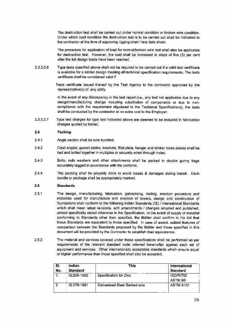
2.5.1 The design, manufacturing, fabrication, galvaniSing, testing, erection procedure andmaterials used for manufacture and erection of towers, design and construction offoundations shall conform to the following Indian Standards (IS) /International Standardswhich shall mean latest revisions, with amendments / changes adopted and published,unless specifically stated otherwise in the Specification. In the event of supply of materialconforming to Standards other than specified, the Bidder shall confirm in his bid thatthese Standards are equivalent to those specified. In case of award, salient features ofcomparison between the Standards proposed by the Bidder and those specified in thisdocument will be provided by the Contractor to establish their equivalence.
2.5.2 The material and services covered under these specifications shall be performed as perrequirements of the relevant standard code referred hereinafter against each set ofequipment and services. Other internationally acceptable standards which ensure equalor higher performance than those specified shall also be accepted.
SI. Indian Title InternationalNo. Standard Standard1. IS:209-1992 Specification for Zinc ISO/Rl752
ASTM B62. IS 278-1991 Galvanised Steel Barbed wire ASTM A131
16
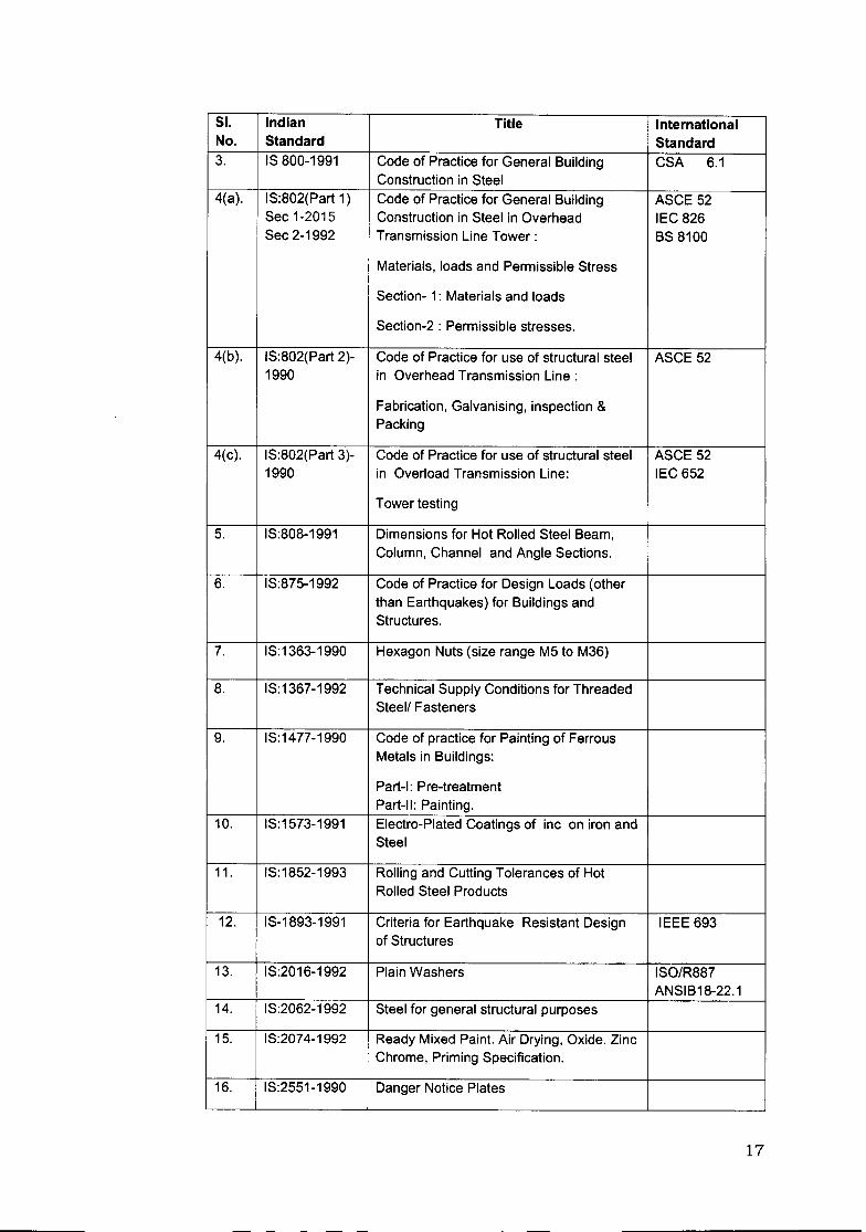
51. Indian Title InternationalNo. Standard Standard3. IS 800-1991 Code of Practice for General Building CSA 6.1
Construction in Steel4(a). IS:802(Part 1) Code of Practice for General Building ASCE 52
Sec 1-2015 Construction in Steel in Overhead IEC 826Sec 2-1992 Transmission Line Tower: BS 8100
Materials, loads and Permissible Stress
Section- 1: Materials and loads
Section-2 : Permissible stresses.
4(b). IS:802(Part 2)- Code of Practice for use of structural steel ASCE 521990 in Overhead Transmission Line:
Fabrication, Galvanising, inspection &Packing
4(c). IS:802(Part 3)- Code of Practice for use of structural steel ASCE 521990 in Overload Transmission Line: IEC 652
Tower testing
5. IS:808-1991 Dimensions for Hot Rolled Steel Beam,Column, Channel and Angle Sections.
6. IS:875-1992 Code of Practice for Design Loads (otherthan Earthquakes) for Buildings andStructures.
7. IS:1363-1990 Hexagon Nuts (size range M5 to M36)
8. IS:1367-1992 Technical Supply Conditions for ThreadedSteell Fasteners
9. IS:1477-1990 Code of practice for Painting of FerrousMetals in Buildings:
Part-I: Pre-treatmentPart-II: Painting.
10. IS:1573-1991 Electro-Plated Coatings of inc on iron andSteel
11. IS:1852-1993 Rolling and Cutting Tolerances of HotRolled Steel Products
12. IS-1893-1991 Criteria for Earthquake Resistant Design IEEE 693of Structures
13. IS:2016-1992 Plain Washers ISO/R887ANSIB18-22.1
14. IS:2062-1992 Steel for general structural purposes
15. IS:2074-1992 Ready Mixed Paint. Air Drying, Oxide. ZincChrome, Priming Specification.
16. IS:2551-1990 Danger Notice Plates
17
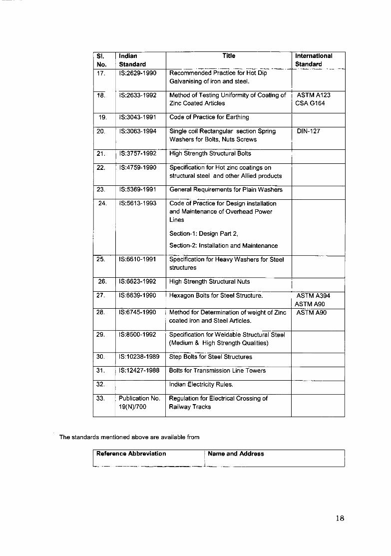
SI. Indian Title InternationalNo. Standard Standard17. IS:2629-1990 Recommended Practice for Hot Dip
Galvanising of iron and steel.
18. IS:2633-1992 Method of Testing Uniformity of Coating of ASTM A123Zinc Coated Articles CSA G164
19. IS:3043-1991 Code of Practice for Earthing
20. IS:3063-1994 Single coil Rectangular section Spring DIN-127Washers for Bolts, Nuts Screws
21. IS:3757-1992 High Strength Structural Bolts
22. IS:4759-1990 Specification for Hot zinc coatings onstructural steel and other Allied products
23. IS:5369-1991 General Requirements for Plain Washers
24. IS:5613-1993 Code of Practice for Design installationand Maintenance of Overhead PowerLines
Section-1: Design Part 2,
Section-2: Installation and Maintenance
25. IS:6610-1991 Specification for Heavy Washers for Steelstructures
26. IS:6623-1992 High Strength Structural Nuts
27. IS:6639-1990 Hexagon Bolts for Steel Structure. ASTM A394ASTMA90
28. IS:6745-1990 Method for Determination of weight of Zinc ASTM A90coated iron and Steel Articles.
29. IS:8500-1992 Specification for Weldable Structural Steel(Medium & High Strength Qualities)
30. IS:10238-1989 Step Bolts for Steel Structures
31. IS:12427-1988 Bolts for Transmission Line Towers
32. Indian Electricity Rules.
33. Publication No. Regulation for Electrical Crossing of19(N)/700 Railway Tracks
The standards mentioned above are available from
Reference Abbreviation Name and Address
18

BIS/IS Beureau Of Indian Standards.Manak Bhavan,9, Bahadur Shah Zafar Marg,New Delhi - 110001.INDIA
ISO International Organisation for Standardization.Danish Board of StandardizationDanish Standardizing Sraat,Aurehoegvej-12DK-2900, Heeleprup,DENMARK.
CSA Canadian Standard Association178, Rexadale Boulevard,Rexdale (Ontario)Canada, M9W 1R3
DIN Deutsches Institute fiir Normung,Burggrafenstrassee 4-10Post Farh 1107D-1000, Berlin 30GERMANY
ASTM American Society for testing and Material1916 Race StreetPhiladelphia. PA1903-1187USA
Indian electricity Rules Kitab MahalRegulation for electricity crossing of Baba Kharak singh Margrailway Tracks New Delhi-110001
INDIAASTM American Society of civil Engineers
345 East 4ih StreetNew York, NY10017-2398USA
IEEE Institute of Electrical and Electronics Engineers445 Hoes LanePiscataway, NJ
0085-1331, USAIEC International Electro technical Commission,
Bureau Central de la Commission,electro Technique international,1 Rue de verembe,GenevaSWITZERLAND
19
2.6 DESIGN OF FOUNDATION
2.6.1 SCOPE
2.6.1.1 This section covers the design requirements of reinforced cement concrete foundations of selfsupporting galvanised lattice towers for 400 kV D/C Transmission line in respect of towers,special towers & body extensions of all types of towers which may be required as per necessityof the site.
2.6.1.2 The payment for different items of foundations shall be restricted to guaranteed volumesquoted in the schedules or actual whichever is less, as per unit rates.
2.6.2 CLASSIFICATION OF SOILS
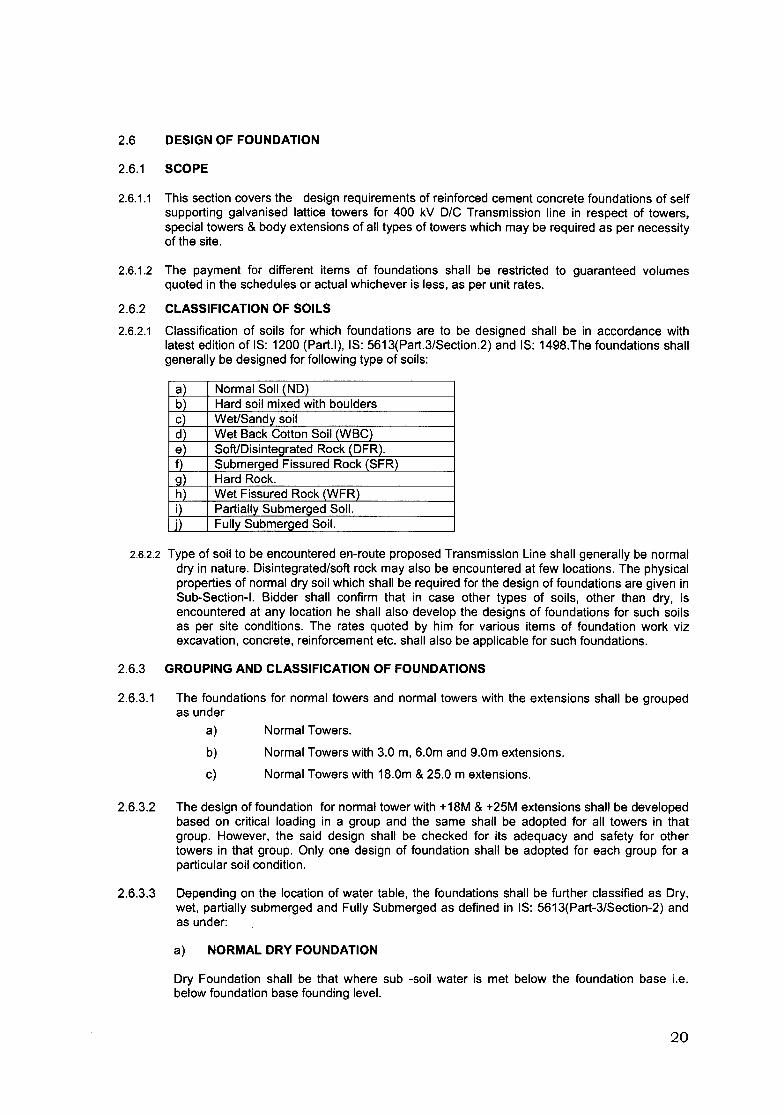
2.6.2.1 Classification of soils for which foundations are to be designed shall be in accordance withlatest edition of IS: 1200 (Part.I), IS: 5613(Part.3/Section.2) and IS: 1498.The foundations shallgenerally be designed for following type of soils:
a) Normal Soil (ND)b) Hard soil mixed with bouldersc) Wet/Sandy soild) Wet Back Cotton Soil_{WBCje) Soft/Disintegrated Rock (DFR).f) Submerged Fissured Rock (SFR)g) Hard Rock.h) Wet Fissured Rock (WFR)i) Partially Submerged Soil.j) Fully Submerged Soil.
2.6.2.2 Type of soil to be encountered en-route proposed Transmission Line shall generally be normaldry in nature. Disintegrated/soft rock may also be encountered at few locations. The physicalproperties of normal dry soil which shall be required for the design of foundations are given inSub-Section-1. Bidder shall confirm that in case other types of soils, other than dry, isencountered at any location he shall also develop the designs of foundations for such soilsas per site conditions. The rates quoted by him for various items of foundation work vizexcavation, concrete, reinforcement etc. shall also be applicable for such foundations.
2.6.3 GROUPING AND CLASSIFICATION OF FOUNDATIONS
2.6.3.1 The foundations for normal towers and normal towers with the extensions shall be groupedas under
a) Normal Towers.
b) Normal Towers with 3.0 m, 6.0m and 9.0m extensions.
c) Normal Towers with 18.0m & 25.0 m extensions.
2.6.3.2 The design of foundation for normal tower with +18M & +25M extensions shall be developedbased on critical loading in a group and the same shall be adopted for all towers in thatgroup. However, the said design shall be checked for its adequacy and safety for othertowers in that group. Only one design of foundation shall be adopted for each group for aparticular soil condition.
2.6.3.3 Depending on the location of water table, the foundations shall be further classified as Dry,wet, partially submerged and Fully Submerged as defined in IS: 5613(Part-3/Section-2) andas under:
a) NORMAL DRY FOUNDATION
Dry Foundation shall be that where sub -soil water is met below the foundation base i.e.below foundation base founding level.
20
b) WET FOUNDATION
Wet Foundation shall be that where sub-soil water rises in the foundation pit upto 1.5 mbelow ground level: or where there is water over the ground for long periods but does notpenetrate beyond 1.0 m below ground at such paddy fields.
c) PARTIALLY SUBMERGED FOUNDATION
Partially submerged Foundation shall be that where sub-soil water rises in thefoundation pit upto 0.75 m to 1.5 m below ground level.
d) FULLY SUBMERGED FOUNDATION
Fully submerged Foundation shall be that where sub- soil water rises in the foundationpit within 0.75 m below ground level.
e) BLACK COTTON SOIL
To be used at locations where soil is clay type, not necessarily black in colour, whichshrinks when dry and swells when wet, resulting in differential movement. For designingfoundations, for such locations, the soil is to be considered submerged in nature.
f) SOFT DISINTEGRATED ROCK
To be used at locations where decomposed or fissured rock gravel, kankar, limestone,laterite or any other soil of similar nature is met. Under cut type foundation is to be used forfissured rock locations. In case of fissured rock locations, where water table is met at 1.5metre or more below ground level wet fissured rock foundations shall be adopted. If after soilinvestigation, water level is encountered at less than 1.5 metre below ground level, aseparate foundation design shall be developed.
g) HARD ROCK
The locations where chiseling, drilling and blasting is required for excavation hard rocktype foundations are to be used. For these locations rock anchoring is to be provided to resistuplift forces. For quoting prices of hard rock foundations rock level shall be assumed at 1.5metres below the ground level due to change in rock level, no extra payment shall be payableon account of increase in concrete volume, excavation volume and weight of reinforcement,also no recovery shall be made, if the actual volume of concrete, excavations and weight ofreinforcement are less than that quoted in Schedule of Prices. However, for design purpose,rock level shall be considered at ground level and no over burden soil weight shall beconsidered for resisting the uplift.
h) SANDY SOIL
Soil with negligible cohesion because of it's low clay content (0-10%).
In addition to the above, depending on the site conditions other types of foundation shall alsobe provided by the contractor suitable for:
a) Intermediate conditions under the above classifications to effect economy: orb) For locations where special foundations (Well type or piles) are necessitated.
The proposal for these types of foundations shall be submitted by the contractor based on thedetailed soil investigation and approval for the same shall be obtained from the Owner.
Note: In all the cases,thewater level shall bemeasuredwith respectto the towercentre line.2.6.3.4 The relevant characteristics of the various types of soils are given in sub section.-I of this
specification .It shall be the responsibility of the Contractor to draw the attention and obtainapproval of the Owner for the departures necessitated in these design data, should he find itnecessary based on his inspection of the site conditions, results of trial pits etc.
2.6.4 FORCES FOR DESIGN OF FOUNDATIONS
21
------_._-
2.6.4.1 The following forces/loads transmitted to foundation by superstructure due to the action of wind,conductor tension, temperature, earthquake etc. acting thereon shall be considered in thedesign of foundation:
a) Maximum Tension/Uplift Forceb) Maximum Compression Force/Down Thrust.c) Maximum horizontal shears/side thrusts in longitudinal and transverse directions.d) Additional forces due to eccentricities in the foundation system(if any)
2.6.5 FACTOR OF SAFETY
2.6.5.1 For structural design of various component of foundation, load factors shall be considered asper IS: 456
2.6.6 STABILITY OF FOUNDATION
2.6.6.1 The foundation shall be designed to withstand the most critical combinations of forces specifiedin Clause 2.6.4.1 multiplied by relevant factors of safety. The stability of foundation, in general,shall be checked for the following aspects.
(a) Stability Against Uplift(b) Stability Against Bearing Pressure of Soil(c) Stability Against Side Thrust(d) Stability Against Overturning(e) Stability Against Sliding
2.6.6.2 The types of soil resistance to be considered for balancing the various imposed forces by thesuperstructure on the foundation shall be considered as under:
(a) RESISTANCE AGAINST UPLIFT FORCES
The uplift force shall be assumed to be resisted by the weight of earth in an inverted frustum ofa conical pyramid of earth on the foundation pad with the sides of the pyramidal cone of earthat an angle equal to the angle of internal friction of the soil with vertical. The weight of concreteincluding reinforcement shall also be considered for resistinq the uplift. In case the frustum ofearth pyramid of two legs superimposes each other, the earth frustum shall be assumedtruncated by a vertical plane passing through the centre line of the tower base. The angle ofinternal friction and density of various types of soils and properties of concrete are given insub- section I of the Specification.
(b) RESISTANCE AGAINST COMPRESSION FORCE/DOWN THRUST
The total compression force/down thrust load including additional effective weight ofconcrete/R.C.C. and weight of embedded steel part shall be resisted by bearing pressure ofthe soil assumed to be acting on the total contact soil area under the footing. The ultimatebearing pressure for various types of soils enroute the 400 kV line is given in sub- section-I.
(c) RESISTANCE AGAINST THE SIDE THRUST
The horizontal shears/side thrusts shall be assumed to be resisted by the passive pressure ofsoil around the footing. The passive resistance of the soil shall be calculated as per Rankine'sformula. In case, complete side thrust is not balanced by available passive resistance of soil,unbalanced part of the side thrusts shall be balanced by bearing pressure of soil under thefooting.
2.6.7 STRUCTURAL DESIGN OF SPECIAL TOWER FOUNDATION
2.6.7.1 Isolated identical footings shall be provided for each leg of the tower.
2.6.7.2 Depending on soil conditions and loading, the foundation of tower shall be one of the followingtypes:
22
(a) SLAB TYPE R.C.C. ISOLATED FOOTING(b) UNDER CUT TYPE ISOLATED R.C.C. FOOTING (For soft rock)
2.6.7.3 SEISMIC FORCES
Design of foundations for towers against seismic forces shall conform to IS: 1893 (Part-I)2002 (latest edition). The basic seismic co-efficient are given in Sub-section I. The importantfactor to be considered in the calculation of seismic forces shall be 1.5 and other factors shallbe as per above code. In the event of award of contract, detailed supporting designcalculations regarding adequacy and safety of foundations against seismic forces shall befurnished by the contractor.
2.6.7.4 All foundations shall be designed so as to satisfy and meet the following requirements:-
(a) The chimney of the foundation shall at least be 300 mm square providing a minimumclear concrete cover of not less than 100 mm over any part of the stub angle in case ofdry foundations and at least 450 mm square with minimum clear concrete cover of notless than 150 mm over any part of the stub angle in case of wet, partially submerged andfully submerged foundations.
(b) The chimney top shall extend 275 mm (minimum) above ground level and coping shallbe upto 75 mm below the joint between the bottom bracing and the leg members.
(c) In all foundations, a lean concrete sub-base having a thickness of 75 mm and of sizeequal to 75 mm more than the R.C.C. footing on all sides shall be provided understructural concrete. The lean concrete shall be of grade M-10 (1:3:6) conforming to IS:456. The lean concrete sub-base provided under the footing shall not be considered inthe structural calculations.
(d) The embedded end of the stub angle shall have a 100 mm thick clear concrete coverupto the top of the lean concrete sub-base in the case of dry foundations and a 150 mmthick clear concrete cover in the case of wet, partially submerged and fully submergedfoundations.
(e) The stub shall extend upto the bottom of foundation having a clear concrete cover asspecified in para(d) above.
(f) The depth of foundation below ground level shall not be less than 3.0 m. However theminimum depth may increase in case of special towers as per design.
(g) The joints between the tower stubs and the superstructure bracing members shall be300 mm above ground level.
(h) The chimney shall be designed for combined action of axial force and net bendingmoment. The maximum compression/tension alongwith both the horizontal shears shallbe considered in the design of chimney. The adequacy of chimney section shall bechecked as per above and necessary reinforcement in chimney section shall be checkedas per above and necessary reinforcement in chimney shall be provided as per designrequirements (the stub shall not be considered as reinforcement). The design shall becarried out in accordance with IS:456. Wherever reinforcement is provided infoundations, the clear concrete cover to reinforcement shall not be less than 50 mm.
U) The centroidal axis of the stub shall coincide with the axis of the chimney and passthrough the centre of the footing base. The design of the foundation shall take intoaccount the additional forces resulting from eccentricity introduced due to noncompliance of above requirements.
2.6.7.5 The slab type isolated R.C.C. foundations for other than normal towers (to be furnished by thecontractor) shall also satisfy and meet the following requirements:
(a) The structural design of foundations shall be strictly in accordance with IS: 456 andother relevant I.S. Codes.
23
(b) The design of R.C.C. foundations shall be carried out by limit state method inaccordance with IS: 456 using load factors as given in the above code.
(c) The minimum thickness of footing slab for foundations shall not be less than 250 mm incase of dry locations and 300 mm in case of wet locations.
(d) The minimum thickness of footing slab at the edges shall not be less than 150 mm asspecified in IS: 456.
(e) In case of stepped foundations, the reinforcement at top face of each step shall beseparately provided. The reinforcement from one step to another step at top face of thefootings shall not be permitted.
2.6.7.6 In the case of rock foundations, the holes in the rock shall be made in an approved manner soas to eliminate the possibility of cracking of rock. The concrete block shall be secured in therock with the help of adequate number of anchor bolts of appropriate diameter grouted with acement mortar containing suitable non-shrinkage admixture.
2.6.7.7 Measurement, Unit Rates and Payment for Foundation
2.6.7.7.1 The indicative shape of foundations is enclosed in this Specification. The bidder is requiredto quote the unit rates for different foundation types for a particular tower in the relevantPrice Schedule.
Normal Foundations - The rate of foundation per tower shall include transportation ofconstruction materials to the Site, excavation, concreting, reinforcement, shoring,shuttering, dewatering, stock piling, dressing, curing, backfilling the foundation afterconcreting with excavated / borrowed earth (irrespective of leads), consolidation of earthand carriage of surplus earth to the suitable point of disposal as required by the Employeror any other activities related to completion of foundation works.
Special Foundations· Any such foundations required during execution of the project andauthorised by the Employer, shall have to be carried out by the Contractor without anyfinancial implication to the Employer. The price of the same shall be deemed to beincluded in the Contract Price.
2.7 FABRICATION
2.7.1 The fabrication of towers shall be in accordance with the provisions made in the followingsub-clauses:
2.7.1.1 Except where hereinafter modified, details of fabrication shall conform to the relevantclause of IS: 802 (Part II)
2.7.1.2 All parts of the towers shall be cut to correct lengths and fabricated in accordance with theshop drawings. Welding of two or more pieces to obtain the length of member specified willnot be allowed. Members shall be straight to the permissible tolerances or better whenrequired to ensure proper fit before being laid off or worked and after galvanising.Contractor shall furnish the shop drawings in standard format to the owner.
2.7.1.3 Normally butt splices shall be used. The components constituting the joint shall have atotal strength greater than the heavier of the members connected. Lap splices may beused for connecting members of unequal sizes. The inside angle of lap splice shall begrinded at the heel to fit the fillet of the outside angle. All splices shall develop full strengthof the members connected through bolts. Butt as well as lap splices shall be made aboveand as close to the main panel points as possible.
2.7.1.4 Joints shall be so designed and detailed as to avoid eccentricity as far as possible.However, where the connections are such that the elimination of gusset plates would resultinto eccentric joints, gusset plates and spacer plates may be used in conformity withmodern practices. The thickness of gusset plates shall not be less than 6 mm. Where agusset plate is required to transmit stress, its thickness shall not be less than the thicknessof the thickest connected bracing members.
24
2.7.1.5 The uses of fillers in the connections shall be avoided as far as possible. The diagonal webmembers in tension may be connected entirely to the gusset plate where necessary toavoid the use of fillers. Each diagonal shall be in one piece without splices or centre gussetand it shall be connected at the point of intersection by one or more bolts.
2.7.1.6 The tower members shall be accurately fabricated to bolt together easily at site without anyundue strain on them or the bolts.
2.7.1.7 No angle member shall have the two leg flanges brought together by closing the angle.
2.7.1.8 All parts of the towers shall be accessible for inspection and cleaning. Drain holes shall beprovided at all points where pockets or depressions are likely to hold water.
2.7.1.9 All similar parts shall be made strictly interchangeable. No rough edges shall be permittedany where throughout the work.
2.7.2 OPERATING IN FABRICATION
2.7.2.1 STRAIGHTENING
Straightening shall be so done that it does not injure the material. Hammering shall not bepermitted for straightening/or flattening of members. Sharp bends shall be a cause forrejection.
2.7.2.2 CUTTING
The cut surfaces shall be clean, smooth, reasonably square and free from any distortion.
2.7.2.3 BENDING
Mild steel angle sections upto 75x75 mm (thickness upto and including 6 mm)shall be bendcold upto and including bend angles of 10 Deg. Angles above 75x75 mm (thickness upto andincluding 6mm) and upto and including 100x100mm (thickness upto 8 mm) may also be bentcold upto bend angles of 5 Deg. All other angle sections and bend angles not covered aboveshall not be bent. All plates upto 12 mm thickness shall be worked cold upto a maximumbend angle of 15 Deg.. Hot bending shall be employed for greater bend angles and thickerplates. All hot bend material shall be air- cooled. The bends shall be of even profile and freefrom any surface damages. Bends on all high tensile steel section shall be done hot.
2.7.2.4 DRILLING AND PUNCHING
Holes in the members shall either be drilled or punched with a jig and shall not be formed byflame cutting process. Drilling or reaming to enlarge holes shall not be permitted. All burs leftby punching or drilling shall be completely removed. Punching may be adopted for M.S.sections with thickness upto 16 mm. For thicker sections, drilling shall be done. The holesnear the bend line of a bent member on both sides of bend line should be punched/drilledafter bending and relative position of these holes shall be maintained with the use of propertemplates/jigs and fixtures. When the tower members are in position, the holes shall be trulyopposite to each other.
2.8 FASTENERS AND JOINTS
2.8.1 It shall be ensured that the fasteners provide positive attachment at all times and under theconditions when the tower structures are subjected to vibrating loads. All tower members shallbe joined together with Bolts and nuts. The redundant members of first two (2) panels fromground level shall be connected with Anti-theft bolts and nuts along with spring washerswhereas the balance joints shall be connected with hexagonal bolts and nuts. All hexagonalbolts and nuts shall conform to IS-12427. They shall have hexagonal head and nuts, theheads being forged out of the solid, truly concentric, and square with the shank, which must beperfectly straight. Anti-theft bolts and nuts shall have round tapered heads with hexagonalshear nuts. They shall confirm to IS 12427 and IS 1367 for property class 5.6/5 except fordimensions which shall be as per enclosed drawing no. SE/400 kV Purchase/017.
25
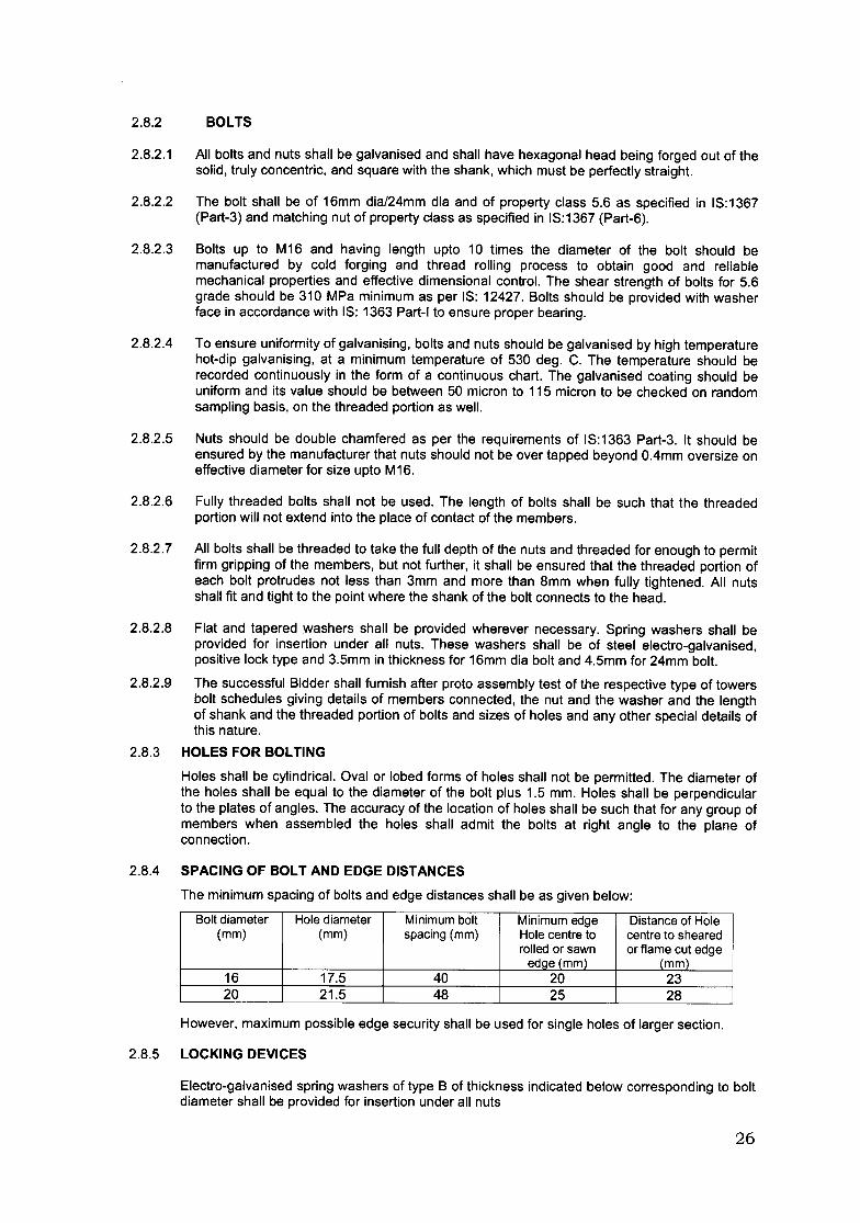
2.8.2 BOLTS
2.8.2.1 All bolts and nuts shall be galvanised and shall have hexagonal head being forged out of thesolid, truly concentric, and square with the shank, which must be perfectly straight.
2.8.2.2 The bolt shall be of 16mm dia/24mm dia and of property class 5.6 as specified in IS:1367(Part-3) and matching nut of property class as specified in IS:1367 (Part-6).
2.8.2.3 Bolts up to M16 and having length upto 10 times the diameter of the bolt should bemanufactured by cold forging and thread rolling process to obtain good and reliablemechanical properties and effective dimensional control. The shear strength of bolts for 5.6grade should be 310 MPa minimum as per IS: 12427. Bolts should be provided with washerface in accordance with IS: 1363 Part-I to ensure proper bearing.
2.8.2.4 To ensure uniformity of galvanising, bolts and nuts should be galvanised by high temperaturehot-dip galvanising, at a minimum temperature of 530 deg. C. The temperature should berecorded continuously in the form of a continuous chart. The galvanised coating should beuniform and its value should be between 50 micron to 115 micron to be checked on randomsampling basis, on the threaded portion as well.
2.8.2.5 Nuts should be double chamfered as per the requirements of IS:1363 Part-3. It should beensured by the manufacturer that nuts should not be over tapped beyond O.4mm oversize oneffective diameter for size upto M16.
2.8.2.6 Fully threaded bolts shall not be used. The length of bolts shall be such that the threadedportion will not extend into the place of contact of the members.
2.8.2.7 All bolts shall be threaded to take the full depth of the nuts and threaded for enough to permitfirm gripping of the members, but not further, it shall be ensured that the threaded portion ofeach bolt protrudes not less than 3mm and more than 8mm when fully tightened. All nutsshall fit and tight to the point where the shank of the bolt connects to the head.
2.8.2.8 Flat and tapered washers shall be provided wherever necessary. Spring washers shall beprovided for insertion under all nuts. These washers shall be of steel electro-galvanised,positive lock type and 3.5mm in thickness for 16mm dia bolt and 4.5mm for 24mm bolt.
2.8.2.9 The successful Bidder shall furnish after proto assembly test of the respective type of towersbolt schedules giving details of members connected, the nut and the washer and the lengthof shank and the threaded portion of bolts and sizes of holes and any other special details ofthis nature.
2.8.3 HOLES FOR BOLTING
Holes shall be cylindrical. Oval or lobed forms of holes shall not be permitted. The diameter ofthe holes shall be equal to the diameter of the bolt plus 1.5 mm. Holes shall be perpendicularto the plates of angles. The accuracy of the location of holes shall be such that for any group ofmembers when assembled the holes shall admit the bolts at right angle to the plane ofconnection.
2.8.4 SPACING OF BOLT AND EDGE DISTANCES
The minimum spacing of bolts and edge distances shall be as given below:
Boltdiameter Holediameter Minimumbolt Minimumedge Distanceof Hole(mm) (mm) spacing(mm) Holecentreto centreto sheared
rolledor sawn or flamecut edgeedge(mm) (mm)
16 17.5 40 20 2320 21.5 48 25 28
However, maximum possible edge security shall be used for single holes of larger section.
2.8.5 LOCKING DEVICES
Electro-galvanised spring washers of type B of thickness indicated below corresponding to boltdiameter shall be provided for insertion under all nuts
26
Bolt Diameter (mm) Thickness of spring washers (mm)16 3.520 4.0
2.8.6 To obviate bending stress in bolts or to reduce the same to a minimum, no bolts shall connectaggregate thickness of more than three times the bolt diameter and also the number carryingstress to be connected by a single bolt shall not generally exceed three(excluding gusset andpacking plates).
2.8.7 The gap between the ends of two connected members in a butt shall not be more than 6 mmand less than 4 mm.
2.8.8 TOLERANCES
2.8.8.1 Fabrication tolerances in general shall conform to IS: 7215 unless otherwise specifiedhereunder:
2.8.8.2 The maximum allowable differences in diameter of the holes on the two sides of the plateshall be 0.8 mm i.e., the allowable taper in a punched hole shall not exceed 0.8 mm ondiameter.
2.8.8.3 Tolerance cumulative and between consecutive holes shall be within ± 1.6 mm.
2.8.8.4 Tolerance on gauge distance shall be within ± 0.5mm.
2.9 ERECTION MARK
2.9.1 Each individual tower member shall carry a code number conforming to the component numbergiven to it in the fabrication drawings. The code number of approved sizes shall be punched onthe member before galvanisation and shall be legible after galvanisation. The letter SAJDA(Tangent Tower), SB/DB (small angle tension tower), SC/DC (Medium angle tension tower),SO/DO (Large angle/Dead-End tension tower) and SCT/DCT (Transposition tower) indicatingthe different types of towers, shall precede the code number in case of towers.
2.10 CHECK ASSEMBLY OF TOWERS
2.10.1 Before proceeding with the bulk fabrication of any type of tower, the Contractor shall fabricateand assemble in his works for inspection by the Owner or his authorised representative, onetower of each type as finally approved by the Owner for checking the fabrication accuracy andworkmanship. The check assembly shall be in a horizontal position. Proto assembly made onground in horizontal position shall be adequately supported to prevent distortion andoverstressing of members to ensure proper fit and shall be accomplished without extra -ordinary efforts to align bolt holes or to force pieces into position. For the check assembly, boltsand nuts shall be not more than finger tight.
2.11 GALVANISATION
2.11.1 Fully galvanised towers shall be supplied .Hot dip Galvanisation of tower members shallconform to IS: 2926 and IS: 4759 and that of fasteners to IS: 5358. Spring washers shall beelectro galvanised with zinc coating Fenz 25 as per IS: 1573. The galvanisation shall be doneafter all the fabrication work is completed except that the nuts may be tapped or re-run aftergalvanisation. Threads of bolts and nuts shall have a neat fit and shall be such that they can beturned with finger throughout the length of the threads of bolts and shall be capable ofdeveloping full strength of the bolts. Excess zinc shall not remain in threads, in holes, atmember ends in connection areas.
2.11.2 All galvanised material shall withstand tests as per IS: 2633.
2.11.3 The stub shall be hot dip galvanised.
27
2.11.4 The finished materials shall be dipped into the solution of dichromate after galvanising ortreated with approved inhibitor (the details of which shall be given in the Bid) for protectionagainst white rust formation during sea transportation.
2.12 STUB TEMPLATES
Stub setting templates shall be designed, fabricated and arranged by the contractor at his owncost at least one set of each type of stub setting template for double circuit towers with orwithout extensions. Stub templates for standard towers and towers with extensions upto 9mshall be of adjustable type. The stub setting templates shall be galvanised. Suitable quantity ofstub setting templates shall be deployed by the contractor for construction of the line.
However, if owner feels that more number of templates are required for timely completion ofthe line, the contractor shall have to deploy the same without any extra cost to owner. One setof each type of stub setting template for double circuit towers, as applicable shall be suppliedto the owner, on completion of the project at no extra cost to owner.
2.13 DRAWINGS AND BILL OF MATERIALS
2.13.1 The contractor shall furnish the following designs and drawing as and when required afterplacement of the order.
i) Fully dimensioned drawing for each standard type of tower complete with crossarms showing sizes of all steel sections, fittings, bolts, attachments etc andclearance diagrams.
ii) Dimensioned drawings for extensions with sizes of steel sections employed.
iii) Dimensioned drawings for stubs.
iv) Dimensioned drawings for stub setting templates.
v) Dimensioned drawings for anti-climbing device.
vi) Loading diagram for all towers under different working conditions inclusive ofrelevant factors of safety.
vii) Stress diagrams for all towers inclusive of 3-metre. 6- metre and 9-metre towerextensions and cross-arms.
viii) Tabulations of stresses under different design assumption, permissiblestresses for various members employed in the towers, extensions and crossarms complete with the following information.
Members reference for identification on stress-diagrams.
Individual loads, inclusive of factors of safety due to transverse, longitudinalvertical, torsional load etc. Under normal and broken wire conditions.Aggregate loads compressive and tensile with factors of safety, based onloadings specified under different conditions.Measured unsupported lengths.Effective unsupported lengths.Appropriate radii of gyration.Sizes of members proposed.Slenderness ratios.Permissible crippling stresses.Gross areas of sections.Permissible crippling loads.No. of size of bolts provided.Net area of sections.Permissible tensile loads.Aggregate cross-sectional areas of bolts.Shearing stress on bolts.Aggregate stress on bolts.Calculated weight of each members.
28
ix) Dimensioned drawings for foundations for each type of tower-3-metre, 6-metre and 9-metre extensions with detailed design computations shall also be provided in soft copy.Drawings shall show all details of keying rods, cleat angles etc., to be provided forconcrete foundations.
x) For foundations of each type of towers the drawings shall indicate the followinginformation:
a) Dimensions of excavation per leg.
b) Volume of concrete.xi) The capacity charts for all types of towers to be used for smaller angles and longer
spans shall be furnished alongwith the Bid.
2.13.2 The contractor shall furnish to the Owner for approval the various contract drawings, bills ofmaterials etc. as called for in the various clauses of this specification. These shall include, butshall not be limited to the following:a) SHOP DRAWINGS
Shop drawings shall list in a space above the title, the part number and required quantity ofeach member detailed on the drawing. Members may be detailed separately or in place in anyassembly.
b) ERECTION DRAWINGS
Erection drawings shall be furnished for each type of tower and extension and shall showassembly diagram of structures clearly indicating the position of each member and the quantityand size of bolts for each joint.
c) BILL OF MATERIALS
A complete bill of material for each type of tower shall be submitted with the erection drawingsindicating each part number, required quantities for one tower section of member length,calculated weight and relevant design drawing reference
d) BOLTS, NUTS AND WASHER SCHEDULE
Bolts, nuts and Washers schedules shall list the number of bolts and washers required pertower alongwith the sizes and lengths of bolts and number, type and size of washers. Theshank length and length of threaded portion of various types of bolts shall be indicated indrawing/table.
2.14 PACKING
2.14.1 The material shall be boxed or bundled for transport in the following manner:
2.14.2 Angles shall be packed in bundles securely wrapped four times around at each end and atevery metre with No.9 gauge galvanised steel wire with ends twisted tightly.
2.14.3 Cleat angles, brackets, fillet plates and similar small loose pieces shall be nested and boltedtogether in multiples, and securely wired together through holes, wrapped round at least fourtimes with No.9 gauge galvanised steel wire and ends twisted tightly. Gross weight of eachbundle shall not exceed approximately 70 kg.
2.14.4 The correct number of bolts, nuts and washers to be packed in heavy gunny bags accuratelytagged in accordance with the contents and a number of bags packed in a solid box of 22 mm,thick lumber with panelled ends to be securely nailed and further reinforced with 22 mm x 18gauge iron band stretched entirely around the battons with ends overlapping at least 150 mm.Gross Weight of each box shall not exceed approximately 70 kg.
The packing shall be carried out with caution to protect the material from moisture, salt or anyimpurities which may cause rust or harmful effects.
29
The packages shall be new and sufficiently sturdy in construction to withstand normal serviceincident to shipping and field handling.
2.15 MARKING OF PACKINGS
Each bundle or package shall have the following marks:
2.15.1 The name and designation of the consignee (to be furnished by the Owner).
2.15.2 The relevant marks and number of tower members, or reference number of bolts, nuts andsmall components like gusset, various attachments, etc for easy identification.
The marking shall be stenciled in indelible ink on the top members in the bundles of tower steeland on wooden boxes or gunny bags containing smaller components.
Detailed despatch instruction shall be asked for by the Contractor from the Owner at least 4weeks ahead of the scheduled date of despatch.
All packages shall be marked with the standard packing mark as desired by the Owner.
2.16 PLACE OF MANUFACTURE AND MANPOWER
2.16.1 The Bidder must have established steel fabrication facilities in his works or at the works of hisAssociates. The galvanising bath/plant & equipment available for fabrication, testing facilitiesavailable in their works and other institution which they intend to make use of and shall not bechanged without the approval of the Owner. The Bidder shall also submit the details ofmanpower available with his Organisation indicating clearly the number of personnel engagedin the design, fabrication of supporting structures and for erection/construction of thetransmission lines. The Bided shall give a brief profile of the Organisation(s).
2.17 AVIATION REQUIREMENTS
2.17.1 Visual aids shall be provided on the transmission line and transmission line structures of height45 M and above to give warning to flying aircraft about the presence of transmission line andtransmission line supports in compliance to the requirement of IS:5613 (part-3/sec.!) 1989(amendment No.1, July 1994). According to this Owner shall have to comply with the following:
2.17.1.1 i) The transmission lines and transmission line structures of height 45 m and above shallbe notified to the Directorate of Flight Safety (DFS), Air Headquarters (Air HQ), New Delhi.
ii) For construction of any transmission line/ structure or a portion thereof, falling within aradius of 20 km around the Defence aerodromes and air to firing ranges provisions of theAircraft Act 1934, Section 9A as amplified by the associated Gazette Notification SO 988 PartII, Section 3, Sub section (ii) dated 1988-03-26 shall be complied with. Towards this, a NoObjection Certificate (NOC) shall be obtained from the concerned aerodrome authorities.
iii) Within a radius of 10 km around aerodromes and air to ground firing ranges, alltransmission lines and structures of height 45 metres or more shall be provided with day andnight visual aids.
iv) In all other areas, outside a radius of 10 km, from aerodromes, only those portions oftransmission lines and structures of any height identified to pose a hazard to aircraft by theDirectorate of Flight Safety shall be provided with day visual aids.
2.17.1.2DESCRIPTION OF VISUAL AIDS
DAY MARKING
i) Line markers: Coloured globules of 600 mm diameter made of reinforced fiber glassor any other suitable material, weighing 5 kg (approx.), with suitable clampingarrangement and drainage holes shall be installed on earth wire(s) in such a mannerthat the top of the marker is not below the level of the earth wire. Up to 400 metre span,one globule shall be provided in the middle of the span on the highest earth wire. In
30

case of double earth wire, the globule may be provided on anyone of them. For spangreater than 400 metres, one additional globule may be provided for every additional200 metres span or part thereof. Half orange and half white coloured globule shall beused.
ii) Structure Marking: The structure portion excluding cross arms above 45 m heightshall be painted in alternative bands of international orange and white colours. Thebands shall be perpendicular to the vertical axis and the top and bottom bands shall beorange. There shall be an odd number of bands. The maximum height of each bandshall be 5M.
Night Marking
Medium and low intensity obstacle lights on a complex obstacle such as towers supportingoverhead wires should have a night time intensity as per ICAO requirements in InternationalStandards recommended practices. The light on top of the structure should flash at the rate of20 sequences per minute.
2.17.2 The contractor shall arrange required data and documents and will assist in preparation/completion of the case to be submitted to the appropriate aviation authorities for obtaining theNo Objection Certificate and shall also extend all help in getting the NOC.
VISUAL AIDS (TO BE PROVIDED)
(A) Day Markings:
a) Painting of Tower
The portion of the towers (excluding cross arms) above 45m height shall be painted over theetched surface in contrasting bands of deep orange or red and snow white as per siterequirement. The band shall be horizontal and minimum three bands shall be provided. Theminimum width of the colour band shall be one meter and not more than 5 mtrs. Followingprocedures shall be adopted for painting of towers.
(i) Surface Preparation
The etching of galvanized surface of erected tower members with wash primer is to be done asper IS: 1477 (part-I) to enhance the adhesion of subsequently applied paint coating. Beforeapplying primer, the tower surface is to be cleaned and it should be free from dust, moisture orany foreign substances. One coat of wash primer is to be applied on the galvanised surfaceand after this second coat of zinchromate primer to be applied after 6 hours, but not later than48 hours. The primer to be used shall conform to IS:2074 (with latest amendment).
(ii) Final Painting
Two coats of international deep orange or red and snow white paint (deep orange or red bandat the top) at alternate interval (bands) as explained above are to be applied. The painting oftowers shall generally conform to relevant provisions in IS: 1477 (Part -II). The syntheticenamel paints to be used for painting shall be in accordance with IS: 2932 (with latestamendment).
b) Line I Span Markers
Sphere type span marker of 600 mm diameter shall be provided on the earth wire. The sphereshall be divided into two parts and one half shall be painted in orange and one half in white.Up to 400 metre span, one globule shall be provided in the middle of the span on the highestearth wire. In case of double earth wire, the globule may be provided on anyone of them. Forspan greater than 400 metres, one additional globule may be provided for every additional 200metres span or part thereof. The design of the markers and their fixing arrangement should besuch that they can withstand the wind pressure and shall not induce excessive amount ofvibrational strain on earth wire. Appropriate clamping device of cast aluminium alloy are to beprovided for clamping. All bolts & nuts are made from stainless steel. The spheres are hollowand UV protected against fading of colour and weathering. Detail of this arrangement shall besubmitted by the Contractor along with Bid.
31
(B) Night Markers (Obstruction lights)
The scope of night markers covers the design, manufacture, testing at manufacturer's work, ifany, supply, delivery, erection, testing and commissioning of medium intensity and low intensitylights along with storage battery & solar panel, control panel, cables, clamps other accessoriesetc. as per the provision of IS-5613 (Part-III Section-1), 1989, amendment No.1, July, 94regarding night & day visual aids for denoting transmission line structures as per therequirement of Directorate of Flight Safety.
The detail of each component of medium intensity, low intensity lights & associatedaccessories to be provided on the towers shall be as per the technical specifications given inthe preceding clauses and IS/ICAO, International Standards recommended practices.
One set of Aviation Lights shall consist of one medium intensity light & two/four (as applicable)low intensity lights along with all accessories such as solar panel, control panel, batteries,cables etc.
The low & medium intensity lights, required for each tower shall be operated through a suitablesize of common battery bank, solar panel as per requirement of operating voltage & loadcurrent of the type of lamps being offered. The lamps shall conform to the ICAO requirement!relevant BS and shall have weather protection of minimum IP-55 class. The burning life of thelamps shall be maximum possible in view of the maintenance hazard of H.T. live line, but in nocase it should be less than 15,000 burning hours. In case of failure of the lamp before 15,000hrs., the same shall have to be replaced by the Contractor free of cost even if the pendency ofcontract expires. Performance certificate of the lamps to be offered shall be furnished by theContractor.
(i) Medium Intensity Light
Medium Intensity light shall be provided on the top of the tower. The medium lightshould have night time intensity as per ICAO requirements in International StandardsRecommended Practices. The light on top of the structure should flash at the rate of 20sequences per minute. The effective intensity during night time for the medium flashing lightshall be 1600 CD. The light shall be equipped with radio suppression facility conforming toBS800 in order to avoid any interference with signals of PLCC etc. The light should meet ICAOspecification & acceptable to the Civil Aviation authorities. Acceptability of the light from CivilAviation Authority, if required, shall be the duty of the contractor. The lights should have testreports from the recognized Government labs for the following:
i. Between 2400-2500 Candela (Cd)/Lux.ii. 360 degree round uniform visibility.iii. Vertical angle min. 3 degree.
(ii) Low Intensity Lights
Twol four (as applicable) nos. of low intensity lights are required to be put on each of thetowers. Placement drawing for the same shall be submitted by the Contractor. The light shallbe stationary lamp with minimum effective intensity of 10 CD of red light. The low intensitylamp shall not generate any R.F. which can interfere with the PLCC signals.
(iii) Storage Battery
Storage Battery required for the above purpose shall be sealed maintenance free, valveregulated lead acid and suitable for mounting on the top of the transmission line towers.Contractor shall offer the most optimum capacity of the Battery Bank at 120 hour dischargerate (considering 80% percentage usage) matching with the load requirement of the type oflamps being offered including any power loss in the associated cables. The battery sizing shallconform to JISC 87071 relevant Indian Standard or any other internationally recognizedstandard. The battery shall be hermetically sealed, explosion proof and self-resealing type andfree from orientation constraints. The working temperature ranges shall be minimum 0 degree
32

centigrade and maximum 50 degree centigrade. Performance certificate of the offeredbatteries shall be submitted by the Contractor.
The battery box suitable for mounting on 400kV power transmission tower shall be robustconstruction suitable to accommodate desired number of SOLAR BATTERIES with properclearance between the batteries. The sides and the top of the battery box shall be made fromMS sheets not less than 14 SWG thicknesses duly mounted on MS angle frame. The bottomof the battery box shall have suitably designed of MS structure to freely hold the total weight ofthe batteries. The batteries should be placed on insulated base with proper drainage holes.Lifting lugs shall be provided. Dust and vermin proof lockable doors shall be provided forsafety and easy access to the batteries for the maintenance. The battery box shouldincorporate the design for proper ventilation system in order to prevent a gas concentrationinside the box. The ventilation opening shall be protected against rain/ splash water and dust.The inside of the battery box shall be lined with insulating polyurethane plating & exteriorpainting with weather proof polyurethane paint. The cable entry into the battery box shall bethrough suitable cable glands.
(iv) Solar Modules
Solar module required for the system shall be suitable for mounting on the transmission linetowers and shall be designed for high performance, maximum reliability and minimummaintenance and shall be suitably installed on the tower. The solar modules shall be IP 55grade protection class. These should be highly resistant to water, abrasion, nail, impact andother environmental factors. These should be placed on the tower at a most optimum angle soas to harness the maximum solar energy and facilitate self cleaning and shall conform torelevant Indian/ International Standards. Module mounting frames shall be weather proofsuitable for mounting on tall towers. Details of mounting frames shall be furnished by theContractor. Junction box shall be provided with weather proof hinged lid with provision forcable glands entry and protections grade of class IP-55. The Contractor shall submit the basisof selecting the numbers of solar modules.
The provision for design, supply & erection of mounting arrangements for photovoltaic moduleson the transmission towers in a suitable manner to harness maximum solar energy shall be inthe scope of the Contractor. Provision for design, supply & erection of resting platform for theerection of battery bank in a closed enclosure with safety arrangement on the transmissiontowers shall also be in the scope of the Contractor. The design and load consideration forsafety of towers due to additional platform shall be kept in view while designing, selecting theabove.
(v) Control Panels.
Control panels shall consist of solar charge controller, flasher unit, sensor, isolator, MCB,Voltmeter, Ammeter and other control gears. Panel enclosure shall be fabricated out of 14SWG CRCA sheet and thoroughly treated and painted. Suitable neoprene rubber gasket andpad locking device shall be provided and the protection class shall be of IP-55 class. The Solarcharge controller shall be most efficient and preferably fully solid state. It shall be providedwith protection to load against increase in temperature, surge, automatic low voltage,automatic disconnection, reconnection during high inrush current and normalcy respectively.
The flash regulator shall be provided for regulating light flashing. The same shall becompletely solid state and provided with flash rate set points. The protection against overloadcurrent shall also be provided. Necessary sensor/ timer shall be provided in the system to"switch on" the light automatically in the evening and poor visibility period and switch off thesame during day time and normal visibility period.
(vi) Cable, Cable Glands, Conduits and Accessories
The cable to be supplied and erected shall be of multi strands copper conductor, weatherproof, PVC insulated, PVC sheathed, armoured 1.1 kV grade. The same shall conform to IS:1554. All the cable accessories such as thimble, glands etc. shall be in the scope of supply anderection of the Contractor. Supply and erection of all the PVC conduits and accessories shallbe in the scope of the contractor. All the conduit and accessories shall be as per the relevantIS or lSI brand. The inter-connection cable/conduit will be clamped in a secured manner with
33
the tower members and any interconnection should be made only inside the environmentallyprotected junction box.
All the installation on the tower shall be securely and earthed with the tower body by usingcopper braided wire. The cost of the earthing deemed to be included in the cost
(vii) Type Test
The items/equipments should have already been type tested. However, the type testcertificates will be reviewed before pre-despatch inspection.
34