rajkot municipal corporation rajkot117.240.113.211/pressrelease/tender_71273_2.pdf ·...
TRANSCRIPT

1
RAJKOT MUNICIPAL CORPORATION RAJKOT
: Name of Work :
Providing, supplying, lowering, laying, jointing, testing and commissioning of 300 mm, 200 mm, 150 mm and 100 mm dia. DI pipeline in T P Scheme No.13 on T P Roads of Shaandar Residency-2 and its adjoining 15 Mt and 9 Mt. T P Roads with necessary connection work in ward No.4 (Re-Tender)
e-TENDER No. RMC/WW/EZ/19-20
:: Milestone dates of e-Tendering ::
1 Downloading of e-TENDER documents 14/02/2020 2. Pre-bid Meeting 20/02/2020 at 17.00 Hours in the Office of the City
Engineer (Sp.)at East Zone. 3. Online submission of e-TENDER 29/02/2020 upto 18.00 Hours 4. Physical submission of EMD, Tender fee,
Documents required for pre-qualification and other necessary documents only by Speed Post or Registered Post or Courier or Hand Delivery.
03/03/2020 upto 18.00 Hours
5. Opening of online Primary Bid (Technical bid) 03/03/2020 at 18.00 Hours 6. Verification of submitted documents (EMD,
Tender fee, Documents required for pre-qualification and other necessary documents.)
04/03/2020 at 11.00 Hours
7. Agency to remain present along with original documents for verification
04/03/2020 Between 16.00 to 17.00 Hours
8. Opening of online Commercial Bid (Price Bid) for Technically qualified bidders only (if possible)
05/03/2020 at 11.00 Hours
9. Bid Validity One Eighty (180) calendar days
VOLUME – II
DETAILED TECHNICAL SPECIFICATIONS
:Authority : City Engineer (Sp.)
Water Works Department, East Zone, Rajkot Municipal Corporation
Shri Zhaverchand Meghani Bhavan Opp.Rajmoti Oil Mill
Rajkot – 360003

2
GENERAL TECHNICAL SPECIFICATIONS 1. Scope of Contract: The work entitled “Water Supply Distribution Network for Providing, supplying, lowering, laying, jointing, testing and commissioning of 300 mm, 200 mm, 150 mm and 100 mm dia. DI pipeline in T P Scheme No.13 on T P Roads of Shaandar Residency-2 and its adjoining 15 Mt and 9 Mt. T P Roads with necessary connection work in ward No.4
The scope of works comprises the following:
Carrying out necessary topographical survey and geotechnical investigations Excavation of pipe trenches in soil, soft rock, hard rock, WBM and concrete
roads, including dewatering. Supplying and Laying of DI pipes with all specials along the route as per the
network map Jointing of pipes with existing pipes(wherever required) with all required
accessories Obtaining statutory approval from railway and other government bodies. Contractor shall plan and accordingly phase the supply of items according to his
requirement to best utilize the available storage space at site. Providing and fixing sluice valves, Scour valves and Air Valves on the existing as
well as new pipeline, as specified in relevant datasheets, detailed technical specifications, particular technical specifications and BOQ.
Providing pipe bedding as per the requirements. Backfilling of pipe trench with selected soil immediately after erection of pipe
excluding pipe joints. Encasing of underground pipelines as per specifications. Hydro testing of pipeline in segments. Backfilling of pipe trench at pipe joints. Construction of RCC Sluice/ Butterfly Valve Chambers/RCC Thrust blocks/
Saddles/ Anchor blocks. The typical drawings for various structures are enclosed in Bid drawings for reference.
Reinstatement of WBM, Tar and Concrete Roads after laying and testing of pipeline.
Demolishing old structures in the route of pipeline, if required. Flushing of entire pipeline with clean water at least for 24 hours. Testing and commissioning. Preparation of as-built drawings.
3
1.1. Delivery Schedule: The contract time shall be as prescribed in tender document, from the notice to proceed. The contractor shall submit his delivery schedule and the programme of works together with his tender in conformity with delivery schedule given in the documents. 1.2. Packing and Handling:
a. Necessary care shall be taken and required packing shall be provided to avoid
damage to pipe barrels and the edges of the pipe ends in transit.
b. Where the goods are required to be dispatched at Railway risk, special packing as per IRCA rules are absolutely necessary, which would be payable by the contractor himself.
c. The contractor shall use proper handling equipment or follow suitable standard
handling method for DI pipes & DI Specials as approved by the Engineer-in- charge to unload the materials at the delivery site to prevent damage to the goods.
d. The contractor shall take all care for Transportation & supply of HC connections
items to be supplied with its standard handling process, stored at site under his store / the delivery site to prevent damage to the goods.
2.0 General Specifications: All the items occurring in the work and as found necessary during actual execution shall be carried out in the best workman like manner as per specifications and as per instructions of the Engineer-in-charge. All material should be from approved vendor for that material
Extra claim in respect of extra work shall be allowed only if such work is ordered to be carried out in writing by the Engineer-in-charge and the same is made in a fortnight after its occurrence.
The contractor shall engage a qualified Engineer for the execution of work who will remain present for all the time on site and will receive instructions and orders from the Engineer-in-charge or his authorized representative. The instructions and orders given to the contractor’s representative on site shall be considered as if given to the contractor himself. A work order book as prescribed shall be maintained on the site of the work by the contractor and contractor shall sign the orders given by the inspecting officers and shall carry out them promptly.

4
Quantities specified in the tender may very at the time of actual execution and the contractor shall have no claim for compensation on account of such variation.
Diversion of road, if necessary, shall be provided and maintained during the currency of the contract by the contractor at his cost.
Figured dimensions of drawings shall supersede measurements by scale. Special dimensions or directions in the specifications shall supersede all other dimensions. All levels are given in drawings and the contractor shall be responsible to take regular levels on the approved alignment before actually starting the work. The levels shall be connected to the G.T.S. levels and shall be got approved from the Engineer-in-charge.
If the arrangement for temporary drainage is required to be made during any work of this contract, this shall be made by the contractor without claiming any extra cost.
3. Classification of Strata : All materials encountered in excavation will be classified in the following groups irrespective of made of excavating the materials and the decision of the Engineer-in-charge in this regard shall be final and binding to the contractor.
3.1. Soils & Hard Murrum: Soils of all sorts, silt, sand, gravel, soft murrum, stiff clay, kunkar and other soft excavation not covered in the items mentioned hereunder. Hard materials comprising of all kinds of disintegrated rock or shale or Indurate conglomerate interspersed with boulders of size between 0.02M3 and 0.75M3, weathered and decomposed rock, which could be removed with, pick, bar, shovel wedges and hammers, thought not without some difficulties. 3.2. Soft-Rock & Hard-rock: This shall include all materials which is rock but which does not need blasting and can be removed with a pick, bar, wedges, pavement breakers, pneumatic etc. This shall include rock occurring in mass or boulders bigger than 0.75 M3 each which need blasting. This will also include rock to be removed by chiseling or any other method where blasting is not permissible.
The contractor will have to arrange for land, power and water for manufacture of pipes. However, if requested by the contractor, the Engineer-in-charge after due verification of facts will recommend to appropriate authority for obtaining land and power for manufacture of pipes under this contract.

5
TECHNICAL SPECIFICATIONS Item No.1, 2, 3, 15, 16 and 17 : Supply of CI sluice valve with IS-14846 & PN-1.0 marked "KIRLOSKAR" brand 300 mm dia Sluice valve 200 mm dia Sluice valve 150 mm dia Sluice valve The Contractor has to prepare approved Quality Assurance Plan (QAP) as per Specification and latest IS Code provisions before manufacturing. Sluice valve as per IS: 14846 or its latest revision.
General
The contractor shall be covering manufacturing, supplying and delivery of sluice valve conforming to IS: 14846 or its latest revision (specification for sluice valves, 50 to 900 mm size) with ISI certification.
Standards
The CI sluice valves to be manufactured, supplied and delivered under the scope of this contract shall be manufactured in accordance with and conforming to Indian standard specifications as given below with ISI certification mark on each sluice valve.
Temperature Variation
All sluice valves manufactured, supplied and delivered shall be subjected to drinking water under variable temperature condition ranging from 4°C to 45°C.
Marking
The legible and indelible marking upon each valve shall indicate the following: (1) ISI certification mark on each sluice valve (2) Manufacture’s brand name and/or trade mark (3) Size of valve and nominal pressure of valve (4) Serial number of cast (5) Serial number in punch (6) Where a valve has been tested for only open-end-test, it should be marked ‘O’ distinctly
and permanently (7) Any other important matter that the manufacturer deems fit to be inscribed embossed
Test Certificate
The contractor shall provide manufacture’s test certificate for every batch / lot of valves manufactured and supplied.
The contractor shall also produce, in addition to the manufacture’s test certificate, the inspection certificate issued by the authorized person / agency appointed by employer for the same purpose. The inspection charges of the authorized person / agency as fixed by employer shall have to be borne by the contractor and the necessary payment to the inspecting agency shall be paid by the contractor as per the terms and condition of employer.

6
Nominal Pressure
Sluice valves shall be designed by nominal pressure (PN) defined as the maximum permissible gauge working pressure in Mpa as “PN-II” (1 Mpa = 10 kgf/m2 approx.).
The nominal size shall refer to the nominal bore at any point, and shall not be less than the nominal size required.
Material
The materials for different component / parts of the sluice valve shall conform to the requirements given in table below:
Materials for Components / Parts of Sluice Valve
Sl. No.
Component Material Reference Grade of Designation
1 Body, bonnet, wedge, stuffing box, gland thrust plate, cap
Grey cast iron 210-FG 1978(1)
2 Stem High tensile brass 320-1962(2) Alloy 1 of 2 3 Wedge nut Leaded tin bronze 318-1962(3) 2 4 Body seat ring,
wedge facing ring Leaded tin bronze 318-1962(3) 2
5 Bolts Carbon steel 1367-1967(4) Class 4.6 6 Nuts Carbon steel 1367-1967(4) Class 4 7 Bonnet gasket Compressed fiber Board 2712-1971(5) C 8 Gland packing Jute & hemp 5414-1969(6) -
(1) Specification for grey iron castings (third revision) (2) Specification for high tensile brass roads and sections (revised) (3) Specification for leaded tin bronze ingots and casting (revised) (4) Specification for technical supply condition threaded fasteners (first revision) (5) Specification for compressed asbestos fiber jointing (first revision) (6) Specification for gland packing, jute and hemp
Manufacture
Sluice valve bodies for 80 mm to 900 mm size valves shall be provided with double-flanged-end connections.
Flanges The flanges and their dimensions of drilling shall be in accordance with part IV and VI of IS: 1538 (Part I to XXII), 1976 (Specification for Cast Iron fittings for pressure pipes for water, gas and sewage) or its latest revision.

7
Constructional Features 1 Standard IS: 2906 above 300 mm size and IS: 780 up to 300 mm size 2 Stem Non rising 3 Ends Flanged, flat faced flanges having off-center bolt holes 4 Bonnet Bolted 5 Disc Solid wedge 6 Operation Manually operated 7 Seat Body - Renewable
Disc - Renewable 8 Other requirements Valves shall close in clockwise rotation of the hand wheel 9 Body & bonnet CI, IS: 210 GR 260 10 Disc CI, IS: 210 GR 260 11 Stem SS, AISI - 410 12 Body seat SS, AISI - 316 13 Disc seat SS, AISI - 316 14 Stem nut Bronze, IS: 318 Gr LTB2 15 Stuffing box CI, IS: 210 GR 260 16 Gland CI, IS: 210 GR 260 17 Packing Graphited Asbestos 18 Bolts, studs & nuts Carbon Steel, IS: 1367 Class 4.6 / 4
Cleaning and Painting
Prior to factory inspection, all manufacturing waste such as metal chips, debris and all other foreign material shall be removed from the interior of the valve. All mill scale, rust, oil, grease, chalk and all other material shall be removed from the interior and exterior surfaces.
Valves shall first be given two coats of zinc base primer after completely cleaning the surface and then it shall be coated with three coats of coal tar epoxy paint. The resulting coating shall be uniform and smooth and adhere perfectly to the surface.
The inside coating shall not contain any constituent soluble in water or any ingredient which could impart any taste or odor to the water.
Testing and Inspection
Valves shall be offered for visual inspection and dimensional check. The hydrostatic testing shall be witnessed by the Employer.
Valves above 300 mm size shall be tested as per IS: 2906. Valves up to 300 mm size shall be tested as per IS: 780.
Valve shall be dispatched only after NAGAR PALIKA approval for dispatch.
Fixing of Valves
Loading at store and unloading at site of works shall be done carefully using suitable mechanical handling devices such as crane, chain pulley etc. The chambers for housing the valves shall have stable and firm foundations. The chamber and top roof cover with removable lid shall be provided so that it shall be possible to remove or replace or recondition the valves seats and to remove the parts without removing the valves from the pipe work. For this, suitable flange adapters may be provided. Butterfly valves shall have high nitrile rubber seats, preferably metal reinforced, unless otherwise specified and shall be installed in the pipe

8
work in such a manner that they can be removed from the line for dismantling and replacement of rubber seats.
Where the valves are required to be operated electrically, actuators shall be sized to guarantee valves closures at maximum possible differential pressure across the valve. Each actuator shall be supplied with installation, instructions and wiring diagrams and sufficient spare parts.
Valves used on pipeline shall be straight, through type, and non chokable. Each valve or its operation equipment shall bear an approved name plate stating its function. All operation spindles, gears and head stocks shall be provided with adequate points for lubrications.
The tightening of nut and bolts shall be done smoothly in such a way that no excessive strain occurs on any one side. The nuts shall be tightened on diametrically opposite site at a time.
Lowering & fixing in position following CI/D/F sluice valves/ reflux valve, Air valve including cost of all labour, jointing material, including nut bolts and giving satisfactory hydraulic testing etc. complete. 300 mm dia sluice valve 200 mm dia sluice valve 150 mm dia sluice valve FIXING OF SLUICE VALVES: Fixing double flange cast iron sluice valves including loading, unloading, carting from store to site including all jointing materials and testing etc, complete.
The sluice valves and tail pieces shall be examined before laying for cracks and other flows. They shall be undamaged in all respect. The sluice valve shall be operated before laying.
All grits and foreign material shall be removed from the inside of the valves before placing.
All the four faces shall be thoroughly cleaned and coated with a thin layer of mineral grease. The tightening of gland shall be checked with a pair of inside calipers. Clearance between the top of the stuffing box and the underside of the gland shall be uniform on all the sides. Jointing materials: The contractor shall provide all necessary jointing materials such as nuts bolts, rubber packing, white zinc, jute, lead, wool etc.
All tools and plant required for installation of sluice valve shall be provided by the contractor.
All jointing materials shall be got approved from the Engineer-in-charge before use.
The nut and bolts shall confirm to latest I.S.S. The rubber packing shall be good quality and approved by the Engineer-in-charge of the work.
9
Installation:
The sluice valve shall be lowered into the trench carefully, so that no part is damaged during lowering operation.
If necessary tail pieces shall be fitted with sluice valve first outside the trench and then lowered into the trench.
The rubber packing shall be three ply and of approved thickness. The packing shall be of full diameter of the flange with necessary holes and the sluice valve bore. If shall be even at both the inner and outer edges. The flange faces thoroughly greased. If flange faces are not free, the contractor shall use thin fibers of lead wood. After placing the placing nuts and bolts shall be inserted and tightened to make the joints.
The valve shall be tightly closed when being installed to prevent any foreign materials from getting in between the working parts of the valve. Each flange bolts shall be tightened a little at a time taking care to tighten diametrically opposite bolts alternatively. The sluice valve shall be installed in such a way that its spindle shall remain in truly vertical position.
The other end of tail piece shall be fitted with pipes so that continuous lines can work.
Extra excavation required for facility of lowering and fixing of sluice valve shall not be paid for. Testing:
After installation of sluice valve the same is tested to 1 ½ times of its test pressure.
The joints of sluice valve shall withstand the test pressure of pipe line.
Defects noticed during test and operation of sluice valve shall be rectified by the contractor at his own cost without any extra claim to the entire satisfaction of the Engineer-in-charge. Mode of measurement and payment:
The measurement shall be taken per number of sluice valve of specified size.
The rate will be per number fitted in a pipe line.
5% amount shall be withheld for hydraulic test and same shall be released after satisfactory hydraulic test. FIXING OF AIR VALVE:
Fixing of cast iron air valve including loading, unloading carting from store to site, drilling and treading, wherever necessary including all jointing materials testing etc. complete.

10
The air valve shall be opened out cleaned and greased and checked properly before fixing.
Before fixing the air valve shall be observed for any damage during transit. Jointing Materials: The contractor shall provide all jointing materials such as G.I. Nipple, M.S. Clamps, nuts, bolts grease white zinc, rubber packing etc.
All tools and plant required for fixing air valves shall be provided by the contractor.
All the jointing materials shall be got approved from the Engineer-in-charge before use.
The nuts and bolts shall conform to latest I.S.S
The rubber packing shall be of good quality and approved by the engineer-in-charge of the work. It shall be three ply of approved thickness. The packing shall be of full diameter of flange with necessary holes and control valve bore. It shall be of even thickness of both inner and outer edges.
M.S. clamps shall be in two semi-circular pieces out of two coupling welded, suitable to the threads and size of single acting air valve. Fittings:
The air valve shall be lowered into the trench, carefully, so that no part is damaged during lowering operation. Double acting air Valve The flanges of the air valve and tail pieces or pipe shall be properly cleaned and greased or applied with white zinc.
The rubber packing of approved quality and of required size shall be inserted on faces of air valve.
If flange faces are not true the contractor shall use thin fiber of lead wool at his own cost.
After placing the rubber packing the nuts and bolts shall be inserted and tightened evenly on all sided properly.
Each bolt shall be tightened a little at a time taking care to tighten diametrically opposite holes alternatively. Testing: The air valve shall be tested during the tested during the testing of the pipe line. The joints and air valve shall be water tight.

11
During test if the joint or air valve, found leaking, the same shall be re-done to the entire satisfaction of Engineer-in-charge. Mode of measurement of payment: The measurement shall be size wise per number and payment shall be made per number of valve fitted.
30 percent of amount shall be withheld for hydraulic test and shall be released after satisfactory hydraulic test. In case of zero velocity valves, Air cushion valves & pressure relief valves shall be tested while running of the pipe line. The measurement shall be taken for number of valve of specified size 30% Amount shall be withheld for hydraulic test and same shall be released after satisfactory hydraulic test. Item No.4 Ductile Iron Pipes with internal cement mortar lining and external Zinc coating with finishing layer of Bitumen; manufactured, tested and duly marked in strict accordance with and confirming to IS: 8329/2000 (as per latest amendment); suitable for push-on Jointing, along-with one number Rubber Gaskets for each length of pipe (EPDM Gasket as per IS: 5382/1985) class-k9 300 mm dia Item No.5 Ductile Iron Pipes with internal cement mortar lining and external Zinc coating with finishing layer of Bitumen; manufactured, tested and duly marked in strict accordance with and confirming to IS: 8329/2000 (as per latest amendment); suitable for push-on Jointing, along-with one number Rubber Gaskets for each length of pipe (EPDM Gasket as per IS: 5382/1985).class-k9 200 mm dia Item No.6 Ductile Iron Pipes with internal cement mortar lining and external Zinc coating with finishing layer of Bitumen; manufactured, tested and duly marked in strict accordance with and confirming to IS: 8329/2000 (as per latest amendment); suitable for push-on Jointing, along-with one number Rubber Gaskets for each length of pipe (EPDM Gasket as per IS: 5382/1985).class- k9 150mm dia Item No.7 Ductile Iron Pipes with internal cement mortar lining and external Zinc coating with finishing layer of Bitumen; manufactured, tested and duly marked in strict accordance with and confirming to IS: 8329/2000 (as per latest amendment); suitable for push-on Jointing, along-with one number Rubber Gaskets for each length of pipe (EPDM Gasket as per IS: 5382/1985).class-k7 100mm dia

12
Item No.11 300 mm dia DI pipeline lowering ,laying and Jointing work Item No.12 200 mm dia DI pipeline lowering ,laying and Jointing work Item No.13 150 mm dia DI pipeline lowering ,laying and Jointing work Item No.14 100 mm dia DI pipeline lowering ,laying and Jointing work Note: The DI Pipe shall be of cement mortar lining inside and zinc coating outside, bitumen coating as per manufacturing and testing IS 8329-2000 with ISI Mark suitable for pushup joint. All pipes with necessary EPDM Rubber Gasket (Rubber gasket IS-5382-1985) with existing GST. A] DUCTILE IRON PIPES & FITTINGS/ SPECIALS : Note: Wherever International Standards or Indian standards / specifications are mentioned, their equivalent or higher standards / specifications are also acceptable Supply and Delivery of Ductile Iron Pipe as per IS:8329-2000 & IS 9523/2000 DI fittings or its latest revision or amendments if any including jointing material as EPDM ring as per IS 5382-1985 and ISO: 4633-1996 or its latest revision or amendments if any. Standards The following standards, specifications and codes are part of this specification. In all cases, the latest revision of the including all applicable official amendments and revisions shall be referred to. In case of discrepancy between this specification and those referred to herein, this specification shall govern. 1) ISO: 10803-1997 Design method for ductile iron pipes 2) IS:8329-2000 Centrifugally Cast (spun) ductile iron pressure pipes for water, gas and sewage & IS 9523 for DI Fittings/Specials. 3) ISO:2531-1991 Ductile iron pipes, fittings and accessories for pressure pipelines. 4) ISO:4179-1985 Ductile iron pipes for pressure and non pressure-Centrifugal cement mortar lining – General requirements. 5) IS:8112 Specification for 43 Grade ordinary Portland cement. 6) BS:3416 Bitumen based coatings for cold application, suitable for use in contact with potable water. 7) ISO:8179-1995 Ductile iron pipes-External coating-Part-1 Metallic Zinc with finishing layer.

13
8) IS:638 Sheet rubber jointing and rubber insertion jointing. 9) ISO:4633-1996 Rubber seals-Joint rings. 10) IS:5382-1985 Specification for Rubber sealing rings for gas mains, water mains and sewers. 11) AWWA C600 Installation of ductile iron water mains and their appurtenances. 1.0 Internal Diameter: The nominal values of the internal diameters of pipe, expressed in millimeters are approximately equal to the number indicating their nominal sizes DN. 2.0 Length: The working length of socket and spigot pipes shall be 5 m ,5.5 m, or 6 metres. 3.0 Thickness: The wall thickness of pipe 'e' in mm shall be calculated as a function of the nominal diameter by the following equation with minimum of 5 mm e = K(0.5 + 0.001 DN) where : e = wall thickness in mm, DN = the nominal diameter, K = the whole number coefficient 4.0 EPDM Rubber Gasket: Rubber Gasket shall be suitably for Push-on-Joint. The spigot ends shall be suitably chamfered or rounded off to facilitate smooth entry of pipe in the socket fitted with the rubber gasket Rubber Gasket shall confirm to IS 5382-1985 and ISO : 4633-1996 its latest revision or amendments if any 5.0 Sampling Criteria: Sampling criteria for various tests, unless specified in IS 8329-2000, shall be as laid down in IS 11606. Mechanical test, Brinell Hardness test, Hydrostatic test etc are shall be as per IS 8329-2000 6.0 Tolerances on External Diameter: The nominal external diameter (DE) of the spigot end of socket and spigot pipes and when measured circumferentially using a diameter tape shall confirm to the requirements specified as follow. The positive tolerance is +1 mm and applies to all thickness classes of pipes. The maximum negative tolerance of the external diameter are specified as follow:
DN Nominal Positive Tolerance Negative Tolerance
80 98 +1 -2.2 100 118 +1 -2.8 125 144 +1 -2.9 150 170 +1 -3.0 200 222 +1 -3.0 250 274 +1 -3.1

14
300 326 +1 -3.3 350 378 +1 -3.4 400 429 +1 -3.5 450 480 +1 -3.6 500 532 +1 -3.8 600 635 +1 -4.0
7.0 Tolerance on Ovality: Pipes shall be as far as possible circular internally and externally. The tolerance for out-or-roundness of the socket and spigot ends is given below:
Nominal Diameter in mm Allowable Difference Between Minor Axis and DE in mm
80 to 300 1.0 350 to 600 1.75 700 2.0 750 to 800 2.4 900 to 1000 3.5
8.0 Tolerance in thickness The tolerance on wall thickness (e) and the flange thickness (b) of the pipes shall be as below:
Dimensions Tolerance in mm
Wall thickness (e) - (1.3 + 0.001 DN )1) Flange thickness (b) + (2+0.05b) & - (2+0.05b)
9.0 Coating Pipe shall be delivered internally and externally coated. External Coating: Pipe shall be metallic zinc coated and after that it shall be given a finishing layer of bituminous paint as per IS - 8329-2000 Zinc coating shall comply with IS:8329/EN 545/ ISO 8179. Only molten zinc spray coating shall be acceptable. The average mass of sprayed metal shall not be less than 130 g/sqm with a local minimum of 110 g/sqm. Bitumen overcoat shall be of normal thickness of 70 microns unless otherwise specified. It shall be a cold applied compound complying with the requirements of BS 3416 Type II suitable for tropical climates factory applied preferably through an automatic process. Damaged areas of coating shall be repainted on site after removing any remaining loose coating and wire brushing any rusted areas of pipe. Internal lining: Internally pipe shall be Portland Cement mortar lined (as per IS - 8329- 2000). The mortar shall contain by mass at least one part of cement to 3.5 part of sand. All pipes and fittings shall be internally lined with cement mortar using high speed centrifugal process in accordance with IWO 4179/IS 8329. Cement mortar lining shall be applied at the pipe manufacturing shop in conformity with the aforesaid standards. No admixtures n the mortar shall be used without the approval of the Engineer. The sand to cement proportion of sand if justified by the sieve analysis. Pipe lining shall be inspected on site and any damage or defective areas shall be made good to the satisfaction of the Engineer. Lining shall be uniform in thickness all

15
along the pipe. The minimum thickness of factory applied cement mortar lining shall be as per IS: 8329 Annex-B or ISO 4179. This is given below.
Nominal Pipe Size (mm) Nominal lining thickness (mm)
Up to 300 3 350-600 5 700-1200 6
1400-2000 9 10.0 Joint Jointing of DI pipes and fittings shall be push-on type Push-on-joints The Contractor shall source the push-on-joint gaskets only from the pipe manufactures. In turn the pipe manufacturer shall supply at least 10% additional quantity of gaskets over and above the requirement to the Contractor at no extra cost. The gasket used for joints shall be suitable for natural and purified water conveyance. In jointing DI pipes and fittings, the Contractor shall take into account the manufacturer’s recommendations as to the methods and equipments to be used in assembling the joints. In particular the Contractor shall ensure that the spigot end of the pipe to be jointed is smooth and has been properly chamfered, so that once the rubber ring is correctly positioned before the joint is made, does not get damaged by friction or sharp edges of the spigot Chamfer. The rubber rings and the recommend lubricant shall be obtained only through the pipe manufacturer. Rubber ring bundles form every lot shall carry with them manufacturers test certificate for the following mechanical properties. 1. Hardness 2. Tensile strength 3. Compression set 4. Accelerated again test 5. Water absorption test 6. Stress relaxation test Rubber rings shall be clearly labeled in bundles to indicate the type of ring, the type of joint, the size of the pipe with which they are to be used, the manufacturer’s name and trade mark, the month and year of manufacture and the shelf life. 11.0 Testing of Pipe: The main test among others to be conducted shall be as per IS:8329-2000 or with its latest revision/amendments. [a] Mechanical Tests Mechanical tests shall be carried out during manufacture of pipes as specified in the Standards. The frequency and sampling of tests for each batch of pipes shall be in accordance with IS 11606-1986. The test results so obtained for all the pipes and fittings of different sizes shall be submitted to Engineer. The method for tensile tests and the minimum tensile strength requirement for pipes and fittings shall be as per IS;8329/EN 545 for pipes and IS:9523/EN 545 for fittings.

16
[b] Brinell Hardness Test For checking the Brinell hardness the test shall be carried out on the test ring or bars cut form the pipes used for the ring test and tensile test in accordance with IS:1500. The test shall comply with the requirements specified in IS:1500/ISO 6506. [c] Re-tests If any test piece representing a lot fails in the first instance, two additional tests shall be made on test pieces selected from two other pipes from the same lot. If both the test results satisfy the specified requirements the lot shall be accepted. Should either of these additional test pieces fall to pass the test, the lot shall be liable for rejection. [d] For hydrostatic test at works, the pipes and fittings shall be kept under test pressure as specified in the standard for a period of minimum 15 seconds during which the pipes shall be struck moderately with a 700 g hammer for confirmation of satisfactory sound. They shall withstand the pressure test without showing any leakage, sweating or other defect of any kind. The hydrostatic test shall be conducted before surface coating and lining. 12.0 Quality Assurance The manufacturer shall have a laid down Quality Assurance Plan for the manufacture of the products offered which shall be submitted along with the tenders and successful tendered shall have to get its approval from RMC. All the materials, pipe, specials, valves etc. shall have to be inspected through Third Party Inspecting Agency. ITEM. Lowering, laying and jointing D. I. K-7 Pipes of various classes with CI / MS specials of following diameters in proper position, grade and alignment as directed by Engineer-in-charge including transportation to site of work, labour, giving hydraulic testing as per IS code etc complete. 300 mm dia DI pipeline lowering ,laying and Jointing work 200 mm dia DI pipeline lowering ,laying and Jointing work 150 mm dia DI pipeline lowering ,laying and Jointing work 100 mm dia DI pipeline lowering ,laying and Jointing work GENERAL: The pipes & joints shall be procured, supplied by the Contractor at work site at his own cost. Every care shall be taken in carting them to site. During transportation any damage shall be occurring to pipes for fittings the replacement of pipes given by the contractor at his own cost. The trenches shall be well leveled so that pipes are laid evenly along them. The pipes shall be fixed within two rubber rings to be supplied by department at the place shown in schedule A, if directed by the Engineer-in-charge or mentioned in item of Schedule B. The specification for titan joints i.e. Rubber Rings shall be as per details specification shown above in item-1. The contractor shall make his own arrangement for obtaining permission for storing & stacking of pipes etc. from land boards whether they are Government, Municipal Local Bodies or Private land owner. Every pipes before lowering into the trenches shall be got checked and thoroughly cleaned and the beds of the trenches shall be properly graded and leveled as required on the line, without any claim for extra cost whether it is required. The pipe shall be carefully lowered into the trenches

17
with the help of a suitable type of chain pulley blocks, which shall first be approved by the Engineer-in-Charge. Each pipe shall be properly jacked and the spigot perfectly fixed into the socket. No jointing operation shall be started unless the gradients levels are approved by the Engineer-in-Charge or his representatives. The pipes shall be laid complete in centerline ranged accurately by means of a string attached to both marked center of site rails and no deviation shall be permissible without the permission of Engineer-in-Charge. The pipe shall be laid in reasonably dry trenches and no circumstances on slushy bedding. The pipes shall be brushed before lowering any laying or remove any soil or dirt etc. that may have accumulated. The inside socket and outside of the spigot-shall be carefully cleaned. The pipe shall be lowered carefully with socket and toward and the flow of water or up till or as directed and spigot and should be carefully inserted into the socket and the space shall be filled with the joint. DI specials shall be conforming to IS 9523-2000 and flanges shall be of PN-10 class. PIPE CUTTING For the installation of bends, branches and valves, pipelines require pieces of pipes of varying lengths. The exact length can only be determined on the site and one must be able to cut the pipes easily, quickly and safely. CUTTING MACHINES Today abrasive disc cutters with various kinds of power supply are used to cut ductile iron pipes. These cutters are powered by electric or compressed air connections or they can be driven indirectly by internal combustion engines. Many of the abrasive disc cutters in the market can be fitted with both abrasive cut off discs for cutting and with roughing discs for rounding off the cut edges. If only one machine is available on site then it should be suitable for both types of discs. Stages in cutting operation The pipe should be placed on level ground or on square timbers in such a way that during cutting, the cutting disc does not become jammed and the remaining pipe wall does not prematurely break away. Marking : A line marked all around the pipe facilitates a straight cut. The line is simply drawn along a steel band which is bent around the pipe. Cutting : Using the cutting disc, the ductile iron and cement mortar pipe wall is cut through completely at one point. The pipe is then cut along the marked line in a single operation. Rounding off : For jointing into sockets of the push - on type, the new spigot end must be chamfered as the original spigot end. Only then the spigot end can be correctly inserted in the socket without damaging the gasket or pressing it out of it’s seat. A roughing disc is used for chamfering.
18
Re-coating : Subsequently, the bare metal surface should be recoated with zinc rich paint and a finishing layer of bitumen. Marking the insertion depth : Before assembling the joint, lines should be marked on the new spigot, showing the correct insertion depth of the spigot end in the socket. TESTING OF WATER PIPES: After each section of the pipeline has been completed it shall be tested for water tightness before being covered. The contractor shall at his own cost fill up water in pipe line and given necessary hydraulic test section by section and the pipe line shall stand the pressure which shall stand the pressure which shall exceed the working pressure by (a) 50% of the highest pressure in the section. (b) 30m whichever is less without showing any leakage or sweating any where in the pipes joints specials valves etc. it any defect are found the contractor shall be made good the same at his own cost. Any leaking joints shall be made good and above test pressure in to be lowered gradually after satisfactory test is & over. Municipal corporation will not be able to provide water for testing of the pipelines & water containers of the project. This shall have to be managed by the contractor at his costs and risk. The hydraulic test shall be given again if considered necessary by the Engineer or his representative to show that no further leakages or sweating is there. The contractor shall have to make necessary arrangements for water testing as well as plugging the open the pipes etc. as directed without claiming any extra cost. The pipelines shall be kept filled with water for a work lines shall be kept filled with water for a week or till it is situated for testing is done. If the pipe lines are laid in detached sanctioned & not in continuous length due to any reasons such as non availability of specials or due to obstacle etc. The contractor shall see that no end of pipes length is kept open-ends are immediately covered up either by suitable blank flange or cap slug or by means of double layer gunny bags clothes tied properly by mild steel wire without any claim for extra-cost. The pipe laying across the state highways, national highways etc. will have to be done either through open cut method or through push through method depending upon the requirement to be prescribed by the sanctioning authority. However, mostly it would be push through method. Mode of Payment : As per schedule B, R.M.C. will pay 90% on receipt of materials at project site, lowering, laying and Jointing as well as refilling and disposal of surplus stuff whereas remaining 10% will be released as per "Break up for Interim Payment" given in Volume-III. B] D. I. SPECIALS / FITTINGS :- SPECIFICATION : Supply of DI Specials, K-7 with ISI marked, conforming to IS 9523/2000 & BSEN:545/1995, suitable for jointing 100 mm to 350 mm dia. DI Pipes shall have the following :

19
A) EXTERNAL COATING :
1. Metallic Zinc with finishing layer of bituminous as per Annexure ‘A’ of IS: 9523/2000. 2. Zinc rich paint with finishing layer of bituminous as per Annexure ’A’ of IS: 9523/2000. 3. Bituminous paint as per Annexure ‘C’ of IS: 9523/2000.
B) INTERNAL LINING : 1. Portland Cement (with or without additives) mortar as per Annexure – ‘B’ of IS:
9523/2000. 2. Cement Mortar with Coal coat as per Annexure ‘B’ of IS 9523/2000. 3. Bituminous paint as per Annexure ‘C’ of IS: 9523/2000.
C) METALURGY & MICRO STRUCTURE :
The metal used for manufacture of D.I. fittings as per IS : 9523-2000 shall conform to the appropriate grade as specified in IS : 1865-2005. D.I. Fittings shall contain a Stub (as cast), minimum length -15mm x dia.- 10 mm., which at the time of Inspection can be cut at random to carry out Metallographic test to ascertain minimum 80% Graphite No dularity as per Clause – 9.1 of IS : 1865-2005, in the form - V or VI as per IS : 7754-2003.
D) MANUFACTURING & VERIFICATION:
All the DI fittings and specials shall conform to IS: 9523/2000 and shall be manufactured at well equipped foundries.
The QAP for the DI fittings shall include inspection of above two by Department’s (/)senior technical representatives and shall necessarily require formal approval before manufacturing clearance. Mode of Payment: As per schedule B Item No.8 Excavation of Paver Road (except for Road works) 1.0 General: 1.1 Any soil which generally yields to the application of the pickaxes and shovels, phawaras
rakes or any such ordinary excavation implement or organic soil, gravel, slit, sand turf lawn, clay, peat etc. fall under this category.
2.0 Cleaning the site: 2.1 The site on which the structure is to be built shall be cleared, and all obstructions, loose
stone, materials and rubbish of all kind, bush, wood and trees shall be removed as directed. The materials so obtain shall be property of the government and shall be conveyed and stacked as directed within RMC limit. The roots of the tree coming in the sides shall be cut and coated with a asphalt.
2.2 The rate of site clearance is deemed to be included in the rate of earth work for which no
extra will be paid.

20
3.0 Setting out:
After clearing the site, the center lines will be given by the engineer-in-charge. The contractor shall assume full responsibility for alignment, elevation and dimension and of each and all parts of the work. Contractor shall supply labors, materials, etc required for setting out the reference marks and bench marks and shall maintain them as long as required and directed.
4.0 Excavation:
The excavation in foundation shall be carried out in true line and level and shall have the width and depth as shown in the drawings or as directed. The contractor shall do the necessary shoring and strutting or providing necessary slopes to a safe angle, at his own cost. The bottom of the excavated area shall be leveled both longitudinally and transversely as directed by removing and watering as required. No earth filling will be allowed for bringing it to level, if by mistake or any other reason excavation is made deeper or wider than that shown on the plan or directed. The extra depth or width shall be made up with concrete of same proportion as specified for the foundation concrete at the cost of the contractor. The excavation upto 1.5 mt depth shall be measured under this item.
5.0 Disposal of the excavated stuff:
The excavated stuff of the selected type shall be used in filling the trenches and plinth or leveling the ground in layers including ramming and watering etc. The balance of the excavated quantity shall be removed by the contractor from the site of work to a place as directed within RMC limit and all lift.
Mode of Measurement and Payment: The measurement of excavation in trenches for foundation shall be made according to the sections of trenches shown on the drawing or as per sections given by the engineer-in-charge. No payment shall be made for surplus excavation made in excess of above requirement or due to stopping and sloping back as found necessary on account of conditions of soil and requirements of safety. The rate shall be for a unit of one squre Meter.
21
Item No.9 and 10 : Excavation for pipeline trenches with shoring, strutting and bailing out or pumping out water from trenches wherever necessary of required length, width and depth including excavation for socket and all safety measures and provisions such as site rails, fencing lighting, watching including refilling the trenches and clearing the site etc as stipulated in the tender specification complete before starting work and after completion of work for the lift and strata as specified below: Excavation of trench for Pipes in Soft Murrum / Clay / Sand & Hard murrum with all safety Provisions (with re-filling of trench) for depth from 0.0 to 1.50 mtr Excavation of trench for Pipes in Soft Rock & Hard Rock Using Breaker, Blasting, Chisel, Hammer with all safety Provisions (with re-filling of trench) for depth from 0.0 to 1.50 mtr Excavation for pipe line trenches with shoring, strutting, bailing or pumping out watered from trenches whenever necessary of required length, width and depth including extra excavations for sockets and all safety measures and provisions such as site rails fencing, lighting, watching including refilling the trenches in layers including ramming and removing the excavated staff with 90m lead and clearing the site etc. as stipulated in the tender specification complete before starting work and after completion of work for all lifts and soil strata as specified.
a) In all sorts of soil soft murmur, hard murrum, boulders, macadam and asphalt
roads including breaking of lime and cement masonry and lime concrete. b) In soft rock, cement concrete, hard rock, and cutting of cement concrete and
R.C.C. of any proportion, etc. with controlled blasting and or chiseling whichever is necessary and feasible as required by site conditions.
c) In hard rock, 1.1 Clearing of sites : 1.1.1 The site at which the pipe line is to laid and the area required for setting out and
other operations shall be cleared of all obstructions, loose stones, and rubbish of all kinds; stumps of trees, brushwood as well as all trees shall be removed as directed. The roots shall be entirely grubbed up.
1.1.2 The products of the clearings to be stacked in such a place and in such a manner, As directed by the Engineer-in-charge.
1.1.3 In site clearing, all trees not specially marked for preservation, bamboos jungle wood and brush wood shall be cut down and their roots grubbed up. All wood and materials from the clearing shall be the property of corporation and shall be arranged as directed by the Engineer-in-charge or his authorized agent. The materials found to be useful by the Engineer-in-charge shall be conveyed and properly stacked as directed within the specified limit. Unless materials will be burnt or otherwise disposed off as directed.
1.1.4 All holes or hollows, whether originally existing or produced by digging up roots, shall be carefully filled up with earth, well rammed and leveled off, as may be directed shall not be paid for. The contractor shall get approval of design of shoring. The shoring shall be of sufficient strength to resist side pressure and ensure safety from slips and blows and to prevent damage to work and property and injury to persons. It shall be removed as directed after all the items of work for which it is required are completed.

22
1.1.5 Protection : 1.1.5.1 The foundation pits and trenches, etc shall be strongly fenced and red light Signals shall
be kept at night in charge of watch-man to prevent accidents. Sufficient care and protective measure shall be taken to see that the excavation shall not affect or damage the adjoining structures. The contractor shall be entirely responsible for any injury to life and damage to the properties etc. Necessary protection work such as guide ropes, crossing places, barricades, the contractor at his own cost shall provide caution boards etc.
1.6 Classification of Strata : 1.6.1 The decision regarding classification of strata shall rest with the Engineer-in- Charge and
his decision shall be final and binding to the contractor.
1.6.2 All the materials encountered in the excavation shall be classified as described in 2.0 of general specifications.
1.7 Dewatering : 1.7.1 Unless specially provided for as a separate item in the contract, the rate of excavation
would include bailing or pumping out all water met with in excavation or which may accumulate in the excavation during the progress of the work either, by percolation, seepage, springs, rain or any other cause and diverting surface flow if any, by earthen bunds or by other means. The bunds shall be removed as soon as the work is completed.
1.7.2 Unless specially provided as a separate item of contract, pumping of water from
foundation pit, trenches etc shall be carried out by the contractor at his won cost and he shall arrange for required numbers of dewatering pumping sets for the above work. He shall take precaution to prevent any damage to the foundation trenches, concrete or masonry or any adjacent structure. The excavation shall be kept free from water by the contractor (1) during inspection and measurement (2) When concrete and/or masonry work are in progress and till the construction work reaches above the natural water level and (3) till the Engineer – in – charge considers that the mortar is sufficiently set. The rate shall be paid for cum. of excavation.
1.8 Excavation in Rock : 1.8.1 Blasting with Gun Power:
Blasting operations shall be carried out with the prior permission and in the presence of the Engineer – in – charge or his authorized representative and during fixed time hours of the day. All safety precautions such as providing safety nylon netting etc. shall be carried out as per instructions of the Engineer – in – charge. Red danger flags shall be prominently displayed and all the people, except those who have actually to light the fuse must be away to a safe distance, not less than 200 meters. All fuses shall be cut to the length required before being inserted into the holes. The number of charges to be fired and the actual number of shots heard shall be compared and the person responsible must satisfy himself by examination that all the
23
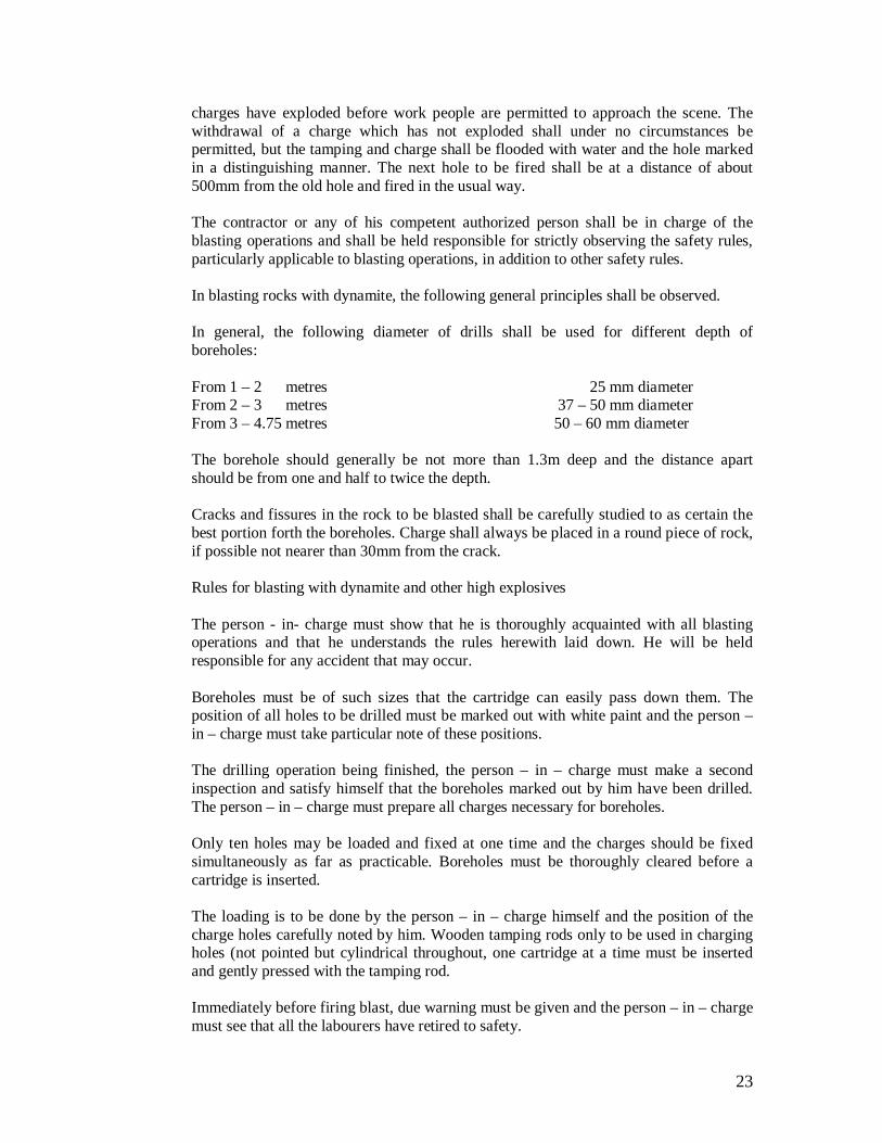
charges have exploded before work people are permitted to approach the scene. The withdrawal of a charge which has not exploded shall under no circumstances be permitted, but the tamping and charge shall be flooded with water and the hole marked in a distinguishing manner. The next hole to be fired shall be at a distance of about 500mm from the old hole and fired in the usual way. The contractor or any of his competent authorized person shall be in charge of the blasting operations and shall be held responsible for strictly observing the safety rules, particularly applicable to blasting operations, in addition to other safety rules. In blasting rocks with dynamite, the following general principles shall be observed. In general, the following diameter of drills shall be used for different depth of boreholes: From 1 – 2 metres 25 mm diameter From 2 – 3 metres 37 – 50 mm diameter From 3 – 4.75 metres 50 – 60 mm diameter The borehole should generally be not more than 1.3m deep and the distance apart should be from one and half to twice the depth. Cracks and fissures in the rock to be blasted shall be carefully studied to as certain the best portion forth the boreholes. Charge shall always be placed in a round piece of rock, if possible not nearer than 30mm from the crack. Rules for blasting with dynamite and other high explosives The person - in- charge must show that he is thoroughly acquainted with all blasting operations and that he understands the rules herewith laid down. He will be held responsible for any accident that may occur. Boreholes must be of such sizes that the cartridge can easily pass down them. The position of all holes to be drilled must be marked out with white paint and the person – in – charge must take particular note of these positions. The drilling operation being finished, the person – in – charge must make a second inspection and satisfy himself that the boreholes marked out by him have been drilled. The person – in – charge must prepare all charges necessary for boreholes. Only ten holes may be loaded and fixed at one time and the charges should be fixed simultaneously as far as practicable. Boreholes must be thoroughly cleared before a cartridge is inserted. The loading is to be done by the person – in – charge himself and the position of the charge holes carefully noted by him. Wooden tamping rods only to be used in charging holes (not pointed but cylindrical throughout, one cartridge at a time must be inserted and gently pressed with the tamping rod. Immediately before firing blast, due warning must be given and the person – in – charge must see that all the labourers have retired to safety.

24
The safety fuse of the charged holes are to be lighted in the presence of the person – in – charge, who must see that the fuses of the holes charged have properly ignited. After the blast, the person – in – charge must carefully inspect the work and satisfy himself that all the charges have exploded.
1.8.2 Misfires: Misfires are a source of great danger, if it is suspected that part of the blast failed to fire or is delayed, allow sufficient time to elapse before entering the danger zone. When fuse and blasting caps are used, a safe time, at least of an hour should be allowed. None of the drillers are to work near this hole until the two following separations have been done by the person – in – charge. (a) The person – in – charge should very carefully extract the tamping with a wooden scrapper and withdraw the fuse with the primer and detonator attached, after which a fresh primer and detonator with fuse should be placed in this hole and fired or. The hole may be cleared of 300mm of tamping and the direction then ascertained by placing a stick in the hole. Another hole may then be drilled 150mm away and parallel to it, the hole to be then charged and fired. The person – in – charge shall also at once report to the Engineer – in charge all cases of misfire, that cause of the same and what steps have been taken in connection herewith.
1.8.2.1 Precautions against misfire: The safety fuse should be cut in an oblique direction with a knife. All saw dust must be cleared from the inside of the detonator this can be done by blowing down the detonator and tapping the open end. No instrument shall be inserted into the detonator for this purpose. After inserting the fuse in the detonator, it shall be fixed by means of nippers. If there is water present, or if the boreholes be damp, the junction of the fuse and detonator must be made water tight by means of grease, white or lead. The detonator should be inserted into the cartridge, so that about one third of the copper tube is left exposed outside the explosives. The safety fuse outside the detonator, should be necessarily tied in position in the cartridge. Water proof fuse only to be used in the damp boreholes, or when water is present in the bore-holes. If a misfire has been found to be due to defective fuse detonator or dynamite, the whole quantity or box from which the defective article was used shall be rejected. Storage of materials for blasting shall be as per regulations/stipulations of the concerned authorities. It shall be the contractor’s responsibilities to arrange proper storage of explosives and obtain required permission from concerned authorities. No separate payment will be made for the above.

25
The refilling will generally refer to refilling of trenches up to ground level with excavated stuff.
Filling materials shall be from excavated stuff. Excavated stuff to be used shall be cleared of all rubbish, large size stones, brick bats etc. Big clods shall be broken down to a size of 50 mm or less. 1.9 Refilling :
After the pipes have been laid and jointed and the chambers are constructed and as soon as the joints have been inspected and passed by the Engineer-in-charge, the pipe line has been tested for water tightness, and after all concrete work thoroughly set the trenches shall be fulfilled with the materials taken there from. In refilling the trenches, the utmost care shall be exercised so as not to disturb, break or damage the jointed pipes. over and around every pipe, the finest selected material shall be put. No lumps of rock earth or other material around the pipe or be thrown into the trenches until the same has been broken to specified size and pipes covered by the fine material above referred to. The selected fine material shall be carefully placed next to the permanent work and well packed and well rammed in layers of 150mm for a depth of at least 300mm over the top of the pipe. The remaining of the excavation shall be filled in with the best and most suitable portions of the excavated material in layers of not more than 600 mm deep, each layer shall be thoroughly rammed before the next layer is placed. One man shall be employed for hand ramming for every 30m of refilling up to the level of 300mm over the top of the pipe. Surplus soil shall be piled on top of the filling to the extent possible for expected subsidence. All road materials to from a compact neat surface. The surface of the filled in trench shall be hand rolled by a hand roller weighing not less the ½ tones as directed by the Engineer-in-charge. The contractor shall maintain all refilling and surfaces until reinstated. The contractor shall responsible for claims arising from accidents due to subsidence or inadequate maintenance or improperly refilling work. The contractor shall be responsible for any settlement during the defects liability period including monsoon and the same shall be refilled with stuff brought from outside, if necessary. Where excavated material is not considered suitable for refilling by the Engineer-in-charge, the Contractor will be required to cart selected surplus excavated materials in place of unsuitable materials. The contractor may also be instructed to supply suitable granular or other hard filling material for use in refilling. Such imported filling material shall be paid for at the rates given in the Bill of quantities. No payment shall be made for carting away surplus material arising either because of rejection of excavated material for refilling or because of surplus material. Measurement: The contractor’s shall be for the unit of one cubic meter of the quantity excavated limited to the dimensions and provisions specified in the specifications or as directed by the Engineer-in-charge. The extra excavation to provide for jointing pipes, shoring etc. will not be paid for. The rates shall include cleaning and clearing the trench site by cutting grass, shrubs and trees of girth (circumference) not exceeding 10 feet and removing their obstructing roots in the trench cleaning the site, setting out works as per sanctioned plans, provide shoring, excavation and removal of all material from trenches, backfilling the trenches up to natural ground level and all other operations

26
described above. The wood obtained during site clearance shall be the property of the department concerned. The excavated quantity divided into two sub groups (a) Excavations up to depth of 1.5M The trench section is to be provided with Max. width OD of pipe + 250mm to300mm either sides. Depth of trench shall be minimum Bedding + OD of pipe + 0.60mt. cover above the top of pipe.(For 100mm dia pipe). Depth of trench shall be minimum Bedding + OD of pipe + 1.0mt. cover above the top of pipe. (For Other dia pipe). Item No.18 and 19: D. I. Specials / fittings :- SPECIFICATION : Supply of DI Specials, K-7 with ISI marked, conforming to IS 9523/2000 & BSEN:545/1995 or relevant or as per requirement, suitable for jointing 150mm to 600mm dia. DI Pipes shall have the following :
D) EXTERNAL COATING :
4. Metallic Zinc with finishing layer of bituminous as per Annexure ‘A’ of IS: 9523/2000. 5. Zinc rich paint with finishing layer of bituminous as per Annexure ’A’ of IS: 9523/2000. 6. Bituminous paint as per Annexure ‘C’ of IS: 9523/2000.
E) INTERNAL LINING : 4. Portland Cement (with or without additives) mortar as per Annexure – ‘B’ of IS:
9523/2000. 5. Cement Mortar with Coal coat as per Annexure ‘B’ of IS 9523/2000. 6. Bituminous paint as per Annexure ‘C’ of IS: 9523/2000.
F) METALURGY & MICRO STRUCTURE :
The metal used for manufacture of D.I. fittings as per IS : 9523-2000 shall conform to the appropriate grade as specified in IS : 1865-2005. D.I. Fittings shall contain a Stub (as cast), minimum length -15mm x dia.- 10 mm., which at the time of Inspection can be cut at random to carry out Metallographic test to ascertain minimum 80% Graphite No dularity as per Clause – 9.1 of IS : 1865-2005, in the form - V or VI as per IS : 7754-2003.
D) MANUFACTURING & VERIFICATION: All the DI fittings and specials shall conform to IS: 9523/2000 and shall be manufactured at well equipped foundries.
The QAP for the DI fittings shall include inspection of above two by Department’s (/)senior technical representatives and shall necessarily require formal approval before manufacturing clearance.

27
Mode of Payment: As per schedule B but supply payment restricted to 90% after laying, jointing etc. complete and 10% will be released after successful hydraulic tests etc complete. Item No.20 3 mm White Rubber Sheet.
The white rubber sheet of 3 mm shall have to be provided and fitting and fixing work with all required material shall have to be carried out and executed as per the requirement and instructions of engineer in charge.
The rate shall be for a unit of one Kilogram. Item No.21 De-watering work for excavation of trench during job work with diesel engine pump set 3 to 5 Hp with suction delivery pipe, fuel and all types of required material etc comp. The De-watering work for excavation of trench during job work with diesel engine pump set 3 to 5 Hp with suction delivery pipe, fuel and all types of required material etc complete shall have to be carried out as per requirement and instructions of engineer in charge to his satisfaction. The rate will be paid for one Hour basis. No extra payment will be made for diesel, transportation etc. at site for this work. Item No.22 Removal of Excavated Stuff and Laying within the sites specified in Notification as directed by Engineer-in-Charge After Refilling the pipe / chamber trenches by the excavated stuff is 15 cm thick layer, including ramming, watering and consolidating up to possible extent as specified in excavation & refilling item, the surplus stuff shall be disposed off at the following sites as directed within the prescribed limits of Notification as directed by the engineering in charge. 1. Beside Kotharia Police Station near Stone Quarry 2. All Quarry areas of Raiya Smart City The excavated material of black cotton soil should be stacked at the location specified by the engineer in charge at no extra cost. If the contractor fails to dispose the excavated stuff as specified, penalty will be imposed by Rajkot Municipal Corporation as per the Notification for C&D waste, After refilling surplus earth shall have to carted by the contractor within specified limit including loading transporting unloading spreading without any extra cost. Mode Of Measurement And Payment: The rate shall be per Cubic Meter of truck-body basis. Asst. Engineer Dy. Executive Engineer City Engineer (Sp.) Rajkot Muni. Corporation Rajkot Muni. Corporation Rajkot Muni. Corporation
Signature of contractor
28
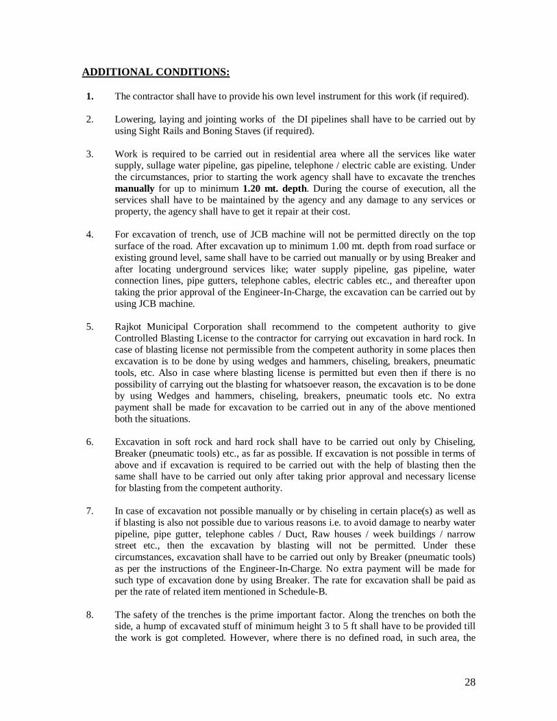
ADDITIONAL CONDITIONS: 1. The contractor shall have to provide his own level instrument for this work (if required). 2. Lowering, laying and jointing works of the DI pipelines shall have to be carried out by
using Sight Rails and Boning Staves (if required). 3. Work is required to be carried out in residential area where all the services like water
supply, sullage water pipeline, gas pipeline, telephone / electric cable are existing. Under the circumstances, prior to starting the work agency shall have to excavate the trenches manually for up to minimum 1.20 mt. depth. During the course of execution, all the services shall have to be maintained by the agency and any damage to any services or property, the agency shall have to get it repair at their cost.
4. For excavation of trench, use of JCB machine will not be permitted directly on the top
surface of the road. After excavation up to minimum 1.00 mt. depth from road surface or existing ground level, same shall have to be carried out manually or by using Breaker and after locating underground services like; water supply pipeline, gas pipeline, water connection lines, pipe gutters, telephone cables, electric cables etc., and thereafter upon taking the prior approval of the Engineer-In-Charge, the excavation can be carried out by using JCB machine.
5. Rajkot Municipal Corporation shall recommend to the competent authority to give
Controlled Blasting License to the contractor for carrying out excavation in hard rock. In case of blasting license not permissible from the competent authority in some places then excavation is to be done by using wedges and hammers, chiseling, breakers, pneumatic tools, etc. Also in case where blasting license is permitted but even then if there is no possibility of carrying out the blasting for whatsoever reason, the excavation is to be done by using Wedges and hammers, chiseling, breakers, pneumatic tools etc. No extra payment shall be made for excavation to be carried out in any of the above mentioned both the situations.
6. Excavation in soft rock and hard rock shall have to be carried out only by Chiseling,
Breaker (pneumatic tools) etc., as far as possible. If excavation is not possible in terms of above and if excavation is required to be carried out with the help of blasting then the same shall have to be carried out only after taking prior approval and necessary license for blasting from the competent authority.
7. In case of excavation not possible manually or by chiseling in certain place(s) as well as
if blasting is also not possible due to various reasons i.e. to avoid damage to nearby water pipeline, pipe gutter, telephone cables / Duct, Raw houses / week buildings / narrow street etc., then the excavation by blasting will not be permitted. Under these circumstances, excavation shall have to be carried out only by Breaker (pneumatic tools) as per the instructions of the Engineer-In-Charge. No extra payment will be made for such type of excavation done by using Breaker. The rate for excavation shall be paid as per the rate of related item mentioned in Schedule-B.
8. The safety of the trenches is the prime important factor. Along the trenches on both the
side, a hump of excavated stuff of minimum height 3 to 5 ft shall have to be provided till the work is got completed. However, where there is no defined road, in such area, the

29
fencing/ lighting etc., requires to be provided as per safety clause. Sign Board shall have to be provided at required locations, so that there will not be any fatal accident.
9. The quantity of various items mentioned in the schedule-B is liable to increase or
decrease up to any extent. Under the circumstances, the contractor shall have to carry out the work accordingly without any rate escalation. Rajkot Municipal Corporation will not entertain any dispute in this regard.
10. In excavation, the decision regarding classification of strata shall rest with the Engineer-
In-Charge and his decision in this regards shall be final and binding to the Contractor. 11. The rates are inclusive of dewatering, if required. 12. In case of any ambiguity found in specifications / drawings etc, the decision of engineer-
in-charge shall be final and binding to the contractor.
13. WORK IN MONSOON: When the work continues in monsoon if required, the Contractor shall maintain minimum labour force required for the work and plan and execute the construction and erection work according to the prescribed schedule. No extra rate will be considered for such work in monsoon. During monsoon and entire construction period, the Contractor shall keep the site free from water at his own cost. However, monsoon period from 1st July to 30th September will be excluded from time limit.
14. The material is to be utilized only after taking the approval from engineer in-charge as
per the Vendor List of Tender as well as GWSSB. 15. During the execution of work and in the route of water pipeline / drainage line and other
additional utilities obstructing the work then the shifting work shall have to be carried out by RMC, however, in case of damage to such obstructing pipeline or other utilities is done by the agency then the rectification to the same and making it good shall have to be carried out by the agency at his own cost.
16. Autocad drawings shall have to be provided in soft copy as well as hard copy, for which,
decision of engineer-in-charge will be final and binding to the agency. Asst. Engineer Dy. Executive Engineer City Engineer (Sp.) Rajkot Muni. Corporation Rajkot Muni. Corporation Rajkot Muni. Corporation
Signature of Contractor
30
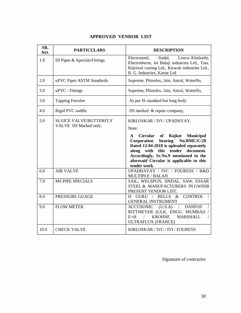
APPROVED VENDOR LIST
SR. NO. PARTICULARS DESCRIPTION
1.0 DI Pipes & Specials/Fittings Electrosteel, Jindal, Lenco–Khalasthi, Electrotherm, Jai Balaji industries Ltd., Tata, Kejriwal casting Ltd., Kiswok industries Ltd., R. G. Industries, Kartar Ltd.
2.0 uPVC Pipes ASTM Standards Supreme, Phinolex, Jain, Astral, Waterflo,
3.0 uPVC - Fittings Supreme, Phinolex, Jain, Astral, Waterflo,
3.0 Tapping Ferrules As per IS standard but long body
4.0 Rigid PVC saddle ISI marked & repute company,
5.0 SLUICE VALVE/BUTTERFLY VALVE ISI Marked only.
KIRLOSKAR / IVI / UPADHYAY.
Note:
A Circular of Rajkot Municipal Corporation bearing No.RMC/C/28 Dated 12-04-2018 is uploaded separately along with this tender document. Accordingly, Sr.No.9 mentioned in the aforesaid Circular is applicable to this tender work.
6.0 AIR VALVE UPADHAYAY / IVC / FOURESS / R&D MULTIPLE / BALAJI
7.0 MS PIPE SPECIALS SAIL, WELSPUN, JINDAL, SAW, ESSAR STEEL & MANUFACTURERS IN GWSSB PRESENT VENDOR LIST.
8.0 PRESSURE GUAGE H GURU / BELLS & CONTROL / GENERAL INSTRUMENT
9.0 FLOW METER ACCUSONIC (U.S.A) / DANFOS / RITTMEYER (I,S,K, ENGG. MUMBAI) / E+H / KROHNE MARSHALL / ULTRAFLUX (FRANCE)
10.0 CHECK VALVE KIRLOSKAR / IVC / IVI / FOURESS
Signature of contractor