ranger qct - válvulas industriales | comeval · the ranger qct is a control valve with a pneumatic...
TRANSCRIPT

TECHNICAL BULLETIN Ranger-TB05-06
RANGER QCTECCENTRIC PLUG
ROTARY CONTROL VALVE(ROTARY GLOBE)
The Ranger QCT is a control valve with a pneumatic spring-diaphragm actuator. It can be supplied with either a flanged or flangeless body style.
This rotary design provides excellent service life in a wide range of applications. Its most unique design feature centers around its Quick Change Trim – QCT. This concept provides front access to the valve body, allowing use of various lo-noise inserts, abrasion sleeve or alternate front-end seal retainers. Also, combinations of these features can be utilized to meet specific application needs.
The Ranger is the most user friendly control valve in the marketplace when it comes to maintenance. It takes a mere five minutes to change trim when out of the pipeline and requires no recalibration.
FEATURES
The Ranger has many important features that provide users with a cost-effective control valve:
• Seven sizes, 1" – 8" (DN25 – 200)• ANSI 150/300/600# pressure class capability with
flangeless body-style *• ANSI 150/300/600# pressure class capability for
flanged body-style in 1"-3" sizes; 150/300# for 4"-8" sizes
• Three body materials• 6 trim combinations• Dual seal rings - soft (Class VI) and metal (Class IV)• Standard live-loaded packing• Ease of maintenance• Multiple reduced port configurations• Cavitation trim• Lo-noise trim• Abrasion sleeve• High capacity• Multi-spring actuator.
* 8" size only available flangeless in ductile iron material.
Ranger QCT –with Siemens Positioner
APPLICATIONS
The Ranger is a universal control valve that is applicable in most control valve applications, especially steam. It pro-vides longer life on difficult services where conventional ball or globe control valves have problems with body or trim wear. It provides noise control for gaseous service, and cavitation and flashing control for liquid service. It is able to withstand temporary distortions due to “thermal shock” without compromising continued control of the process.
Ranger TB.indd 1 5/31/06 9:11:25 AM

2 Ranger-TB
1", 1-1/2", 2", 3", 4", 6" and 8".(DN25, 40, 50, 80, 100, 150, 200.)
DI – ASTM A395.CS – ASTM A216, Gr. WCB.SST – ASTM A351, Gr. CF8M.See Table 1A, 1B & 1C from material specifications.
Body Sizes:
Body Materials Pressure/ Temperature Ratings:
BODY SUB-ASSEMBLY SPECIFICATIONS
TABLE A – PARTIAL TRIM MATERIALSBody Size Option Body Port Seal Retainer Cage Plug Bearings
1", 1-1/2", 2", 3"(DN25, 40, 50, 80)
None
DI, CS All 316 SST Cast 316 SST Nitronic 60SST All 316 SST Cast 316 SST Nitronic 60
4"(DN100)
DI, CS Full CS Cast 410 SST Nitronic 60DI, CS Reduced, AC, LN 316 SST Cast 410 SST Nitronic 60SST All 316 SST Cast 316 SST Nitronic 60
6" & 8"(DN150, 200)
DI, CS Full CS Cast 416 SST Nitronic 60DI, CS Reduced, AC, LN 316 SST Cast 416 SST Nitronic 60SST All 316 SST Cast 316 SST Nitronic 60
1", 1-1/2", 2", 3"(DN25, 40, 50, 80)
Opt-40
CS, SST All 316 SST
Cast 316 SST Nitronic 604", 6", 8"
(DN100, 150, 200)CS
Full CSReduced, AC, LN 316 SST
SST All 316 SST
Hardness - RcCast 17-4 PH 30–38Chrome Plate 60–65
Cast Stellite #6B 37–42ENC - heat treated 66–69
Trim: See Table A below for trim materials determined by body materials or option number.See Tables 3 and 3A for trim designation numbers and material specifications.
Base material as indicated in Table 3 and footnote.
Eccentric Plug:
Stem Sub-Assembly:
Retainer Sleeve Sub-Assembly:
Stem Retainer Screw:
Yoke:
Yoke Bolting:
Packing Assembly:
As indicated in Table 3. Work-hard-ened 316 SST pin joining “groove” end to stem for 17-4PH stem; Nitronic 50HS for Nitronic stem.
As indicated in Table 3; insert material is non-removeable.
316 SST.
1", 1-1/2", 2" – CS rectangular steel tubing.
3", 4", 6", 8" – Ductile iron.
18-8 SST studs, cap screws and nuts.
Common Parts for “Live-Loading”: Retainer & Spacer – 316 SST Belleville Spring Washers – SST Packing Follower – 18-8 SST Packing Flange – 18-8 SST
Studs, Nuts & Washers – 18-8 SST Follower Bushing Bearing – TFE.Standard: TFE V-rings and adapters;
non-split.Optional: Flexible graphite die-formed
into lower density, interlocking rings, with higher density adapter rings, and top/bottom braided graphite filament rings.
TFE: Glass-filled.TFE: Carbon-filled.
316 SST.
18-8 SST cap screw.
250/125 micro-inch Ra (equivalent to 250/125 AARH). Suitable for use with spiral-wound metallic gaskets.
Not supplied with valve unit. Use only steel or stainless steel piping flanges; socket weld, slip-on, or weld-neck types; RF or FF.
Per ANSI B16.5 Dimensions: All sizes of CS, SST or DI body material; 150# or 300# flange pressure class.
All sizes of CS and SST body material;
Soft Seal Ring:
All Inserts:
Seal Retainer Screws:
Flange Surface Finish:
Clamping Companion Flanges:
Ranger TB.indd 2 5/31/06 9:11:26 AM

3Ranger-TB
600# flange pressure class.
Per DIN Dimensions: May be installed between PN40 flanges.
Per ISA – S75.04 for flangeless control valves. See Figure 11, dimension “E”. Integral flanged units meet the same dimensions.
Standard Construction: P = Ambient ≈ 0 psig (0 Barg).Opt -38V Packing @ Vacuum: P = Full Vacuum = 0 psia (0 Bara).
Standard & Reverse flows.
Plug Travel:
Cv Capacity:
Stem Packing:
Gasket:
Painting:
Field reversible sizes 1" through 4" (DN25–100); sizes 6" & 8" (DN150 & 200) require replacement of metal seal ring.
Standard – Standard flow direction. Dual seal rings; composition soft seal
with metallic backup seal. Inlet pres-sure assists sealing.
Optional – Reverse flow direction. Inlet pressure does not assist seal-
ing. Reverse flow may increase seat leakage.
Per ANSI/FCI 70-2 @ ∆Pmin ≥ 50 psi (3.45 Bar).
Function of seal retainer and lo-noise trim.
Body Face-to-Face Dimensions:
Minimum Body Pressure:
Flow Direction:
Seat Design:
Seat Leakage:
Rangeability:
Seal Retainer Flow DirectionFull or Reduced Port Both
Anti-Cav - AC Reverse Flow
Lo-N
oise LNA, LNB
BothLNC, LND
Standard – 0°-to-90° rotation.
Function of seal retainer and internal lo-noise trim. See Tables 6 through 9.
Seal Retainer Seal Ret. Only Seal Ret. + LN InsertFull Port 125:1 80:1
0.6 Reduced Port 75:1 50:10.4 Reduced Port 50:1 35:10.2 Reduced Port 25:1 15:1
Anti-Cav - AC1,AC2 20:1 N/ALo-Noise - LNA,LNC 80:1 30:1Lo-Noise - LNB,LND 60:1 25:1
Body Size Max Cv Max Kv1" (DN25) 14 12
1-1/2" (DN35) 25 212" (DN50) 71 613" (DN80) 170 146
4" (DN100) 325 2806" (DN150) 710 6128" (DN200) 710 612
NOTE: Kv = Cv/1.16; Kv is metric flow coefficient.
Standard: Patented “live-loaded” V-ring packing using Belleville spring washers (see Fig.1); body with integral extended bonnet. Temperature Range -325° ≤ T ≤ 750°F (-198° ≤ T ≤ 400°C), with exposed, uninsulated bonnet above 400°F (205°C).
Opt-38 HT: For high temperature ser-vice; live-loaded, solid ring packing. Temperature range -20° ≤ T ≤ 750°F (-29° ≤ T ≤ 400°C), with insulated bonnet.
Opt-38V: For continuous vacuum service; same as standard, except V-rings are inverted.
Standard – 316L SST formed chevron cross section, spirally wound type, flexible graphite filled.
Standard. All non-stainless steel por-tions of basic unit assembly painted with corrosion resistant epoxy paint per Cashco Spec #S-1606. No paint on tubing or tube fittings. Ac-cessories – standard paint received from suppliers.
Optional. Two-step, extra thick epoxy coating ; Opt-95.
Ranger TB.indd 3 5/31/06 9:11:26 AM

4 Ranger-TB
FIGURE 1:Ranger Body Sub-Assembly Cutaways
Ranger TB.indd 4 5/31/06 9:11:27 AM

5Ranger-TB
ACTUATOR TECHNICAL SPECIFICATIONS0–90° Rotary. Spring-diaphragm type. Rolling diaphragm with multiple springs. Enclosed linkage. Field-re-versible for “direct” or “reverse” action (see Figure 2). Standard with manual handwheel operator.
Figure 2:Plug vs. Lever Arm vs. Actuator Orientation
Size, Stroke & Volume:
BasicModel
No.
NominalDiaphragm
Areain2 (cm2)
Lever ArmLength
in (mm)
NominalStroke *in (mm)
Volumes
Clearancein3 (cm3)
Volumetricin3 (cm3)
48D48R 48in2 (310) 1.375 (34.9) 1.94 (49.3) 27in3 (440) 87in3 (1425)
148D148R 148in2 (955) 1.875 (47.6) 2.65 (67.3) 90in3 (1475) 372in3 (6095)
* To generate 90° rotation.
Maximum Operating Supply Pressure:
Ambient Temperature Range:
Air Connection:
Travel Stop Screw:
Stroking Time:
48 D/R = 20 psig (1.38 Barg).148 D/R = 36 psig (2.48 Barg).
-20° ≤ Tamb ≤ 180°F.(-29° ≤ Tamb ≤ 83°C).
1/4" female NPT.
Standard – Limits travel to 0°–90° rotational travel.
Reference STKSP-TB for stroke times with various accessories.
Basic Design:
Action Model No. Body Size Bench Setting Range
Direct; ATC-FO(Increase in air“LOAD” rotatesvalve stem CW,closing valve)
48D-01 1", 1-1/2", 2"(DN25, 40, 50)
5–15 psig(0.34–1.03 Barg)
148D-01 3"(DN80)
5–13 psig(0.34–0.90 Barg)
148D-02 4", 6", 8"(DN100, 150, 200)
10–26 psig(0.69 – 1.79 Barg)
Reverse; ATO-FC(Increase in air“LOAD” rotates
valve stem CCW,opening valve)
48R-01 1", 1-1/2", 2"(DN25, 40, 50)
5–15 psig(0.34–1.03 Barg)
148R-01 3"(DN80)
5–13 psig(0.34–0.90 Barg)
148R-02 4", 6", 8"(DN100, 150, 200)
10–26 psig(0.69 – 1.79 Barg)
ATC-FO = Air-to-Close, Fail Open;ATO-FC = Air-to-Open, Fail Close.NOTE: No actuator bench setting range selection required; i.e. oneactuator for each body size, except 4" size.
Ranger TB.indd 5 5/31/06 9:11:27 AM

6 Ranger-TB
ACTUATOR SUB-ASSEMBLY MATERIAL SPECIFICATIONSCast aluminum; ASTM B108, Alloy 319.
Epoxy coated steel.
Rolling-type; Buna-N with polyester fabric.
Cast aluminum.
Cast iron.
316 SST.
Naval brass.
Plated malleable iron.
18-8 SST with Buna-N insert.
18-8 SST.
Plated steel and SST.
Plated steel.
SST with SST bolt and nut.
SST.
SST.
OPTION SPECIFICATIONS
Plate – SST with high visibility red indicating zone displaying degree of valve “opening”.
Housing – 48D/R – aluminum; 148D/R – cast iron.
Lens – plastic.Coverplate – SST.External screws – SST.Outboard stem bearing – steel ball
bearing.NOTE: With 991, 9540R, and PS2 the position indicator is integral with positioner, and housing is cast iron.
Figure 3: Model 148R Actuator with 73 P/PPositioner with Manual Handwheel Operator
Casting & Diaphragm Plate:
Springs:
Diaphragm:
Handwheel:
Arm Housing:
Handwheel Stem:
Handwheel Gland:
Locking Lever:
Threadseal:
Flange Bolting:
Turnbuckle Assembly:
Travel Stop Screw & Jamnut:
Lever Arms:
Cam/Spacer:
Nameplate:
Position Indica-tor Assembly with 73 P/P Positioner:
Option-3: NO MANUAL HANDWHEEL OP-ERATOR. A handwheel and locking lever is supplied as standard for the Ranger. This option covers supplying the unit with NO handwheel operator.
Reverse Action; ATO-FC: Actua-tor provided with adjusting screw assembly to assist for internal trim removal (see Figure 4).
Direct Action; ATC-FO: Actuator provided with plug in opening upon removal of handwheel assembly (see Figure 4).
NOTE: Requires that actuator be pressurized to stroke the plug to near “closed” position, properly orienting tongue and groove connection to allow disengagement for trim removal.
Ranger TB.indd 6 5/31/06 9:11:28 AM

7Ranger-TB
Direct ActionReverse Action
Shown with flangeless body
Specify Opt-7C line bolting for flange-less designs only.
See Table 3 for recommended trim designation numbers for cryogenic service along with minimum cryogenic temperatures recommended.
Option-38HT: HI-TEMP PACKING. Standard TFE V-ring packing is replaced with live-loaded flexible graphite ribbon die-formed into interlocking rings with high density graphite adapters and top/bottom braided graphite fila-ment rings. Primarily recommended for higher temperature service. Use of this optional packing REQUIRES USE OF A VALVE POSITIONER.
Option-38V: VACUUM PACKING. Same as stan-dard V-ring packing, except V-rings are inverted (with respect to standard) to seal against air ingress. Orient valve “outlet” to be exposed to the highest vacuum level.
Option-40: NACE SERVICE: Apply only with CS or SST body materials. For sour gas or liquid applications. Specify only trim designation nos. CT1 & CT2. Meets National Association of Corrosion
Engineering (NACE) materials stan-dard #MR0175-90, for exposure of valve internals to fluids with sour gas (H2S) present. Requires use of CF8M (cast 316 SST) cage and Nitronic 60 bearings in CS body sizes 4", 6" and 8" (DN100, 150, 200).
Temperature range: -20° ≤ T ≤ 400°F (-29° ≤ T ≤ 205°C°).
Figure 5: Option-18, Slurry TrimOption-7: LINE BOLTING. For flangeless units
only. See Figure 12 for required dimen-sions and installation clearances.
Opt-7A: Heat treated, alloy steel studs per ASTM A193, Gr. B7; carbon steel nuts per ASTM A194, Gr. 2H. Temperature Range: -20° ≤ T ≤ 750°F (-29° ≤ T ≤ 400°C).
Opt-7C: Full cryogenic, corrosion resistant, 18-8 SST (316 SST) strain-hardened studs per ASTM A193, Gr. B8M; 18-8 SST nuts per ASTM A194, GR. 8M.
Temperature Range: -325° ≤ T ≤ 750°F (-198° ≤ T ≤ 400°C).
Option-18: SLURRY TRIM. Includes a drilled and tapped (1/8" female NPT, with pipe plug) stem retainer screw to allow purge of neck (bonnet) area of valve body. Fluorocarbon elas-tomer O-ring impedes ingress of flowing solids into neck zone. Used primarily with saturated solutions that form hard, crusty buildup upon cool-ing, eventually causing stem “bind-ing”. Includes abrasion sleeve with body sizes 1-1⁄2" – 8". See Figure 5. Temperature Range: -20°F≤T≤400°F (-29°≤T≤205°C).
Option-36: SST CRYOGENIC. Apply only with SST body material. Includes special cleaning of body per Opt-55. Standard V-ring, live-loaded stem packing. Rec-ommended orientation is with stem vertical in a horizontal pipe. Limited to ANSI 150# or 300# pipe systems.
Temperature Range: Full cryogenic, -325° ≤ T ≤ 150°F (-198° ≤ T ≤ 66°C).
Figure 4:Option-3: No Manual Handwheel Operator - Casing Closure
Ranger TB.indd 7 5/31/06 9:11:29 AM

8 Ranger-TB
Option-55: SPECIAL CLEANING. Cleaning per Cashco Spec. #S-1134. Only ap-plicable for SST body material. Ac-ceptable cleaning level for oxygen gas service. Use for non-cryogenic, oxygen service.
Option-56: SPECIAL CLEANING. Applicable for all body materials. Cleaning per Cashco Spec. #S-1542. Not suitable for oxygen service.
Option-95: EPOXY PAINTING. Two-step, extra thick (nominal 4 mil) epoxy coating for severe ambient conditions to minimize external corrosion. Applied to all non-SST exposed parts of basic valve. May be applied to accessories – airset, positioner, transducer, etc., – when specifically requested. Per Cashco Spec #1547.
“QCT” – RELATED TRIM VARIATIONSAnti-cavitation (AC) trim eliminates or reduces the level of cavitation present in clean liquid service. It locates any cavitation to a point where the valve body and internal trim are spared any damage effects. (Also effective in flash-ing services.) See Figure 6.
The AC seal retainer design concept utilizes a network of 2-stage orifices to accomplish the following: • Generate smaller vapor bubbles • Locate the bubbles near the seal
retainer • Hasten downstream bubble im-
plosion • Direct flow to downstream pipe
center • Reduce noise • Reduce vibration • Reduce downstream pipe wall
damage.
The AC seal retainer requires reverse flow direction. Seat leakage is main-tained to Class IV or better. See Table 3 for pressure drop limitations for AC trim. See Table 8 for flow coefficients.
Three sizes of Reduced Orifice Trims are available for the Ranger QCT – 0.2, 0.4 and 0.6 Cv.
Reduced Orifice Trim is recommended to improve control loop resolution for control valve installations when a line sized valve is more economical than pipe reducers and smaller valves, or when future increases in capacity are planned. See Figure 6.
Reduced Orifice Trims utilize elongated openings to control the maximum Cv while maintaining the inherent flow characteristic of the standard trim.
Anti-Cavitation Trim:
Reduced Orifice Trim:
Seat leakage is the same as standard full size trim.
LNA/LNB are similar to the AC1/AC2 seal retainer, except that a soft seal can be installed and the intent is for gas service up to 400°F (205°C) or steam service up to 366°F (186°C). See Figure 8.
Shown with flangeless body
Figure 6:Anti-Cavitation - AC Trim
Figure 7:Reduced Orifice Trim
Shown with flangeless body
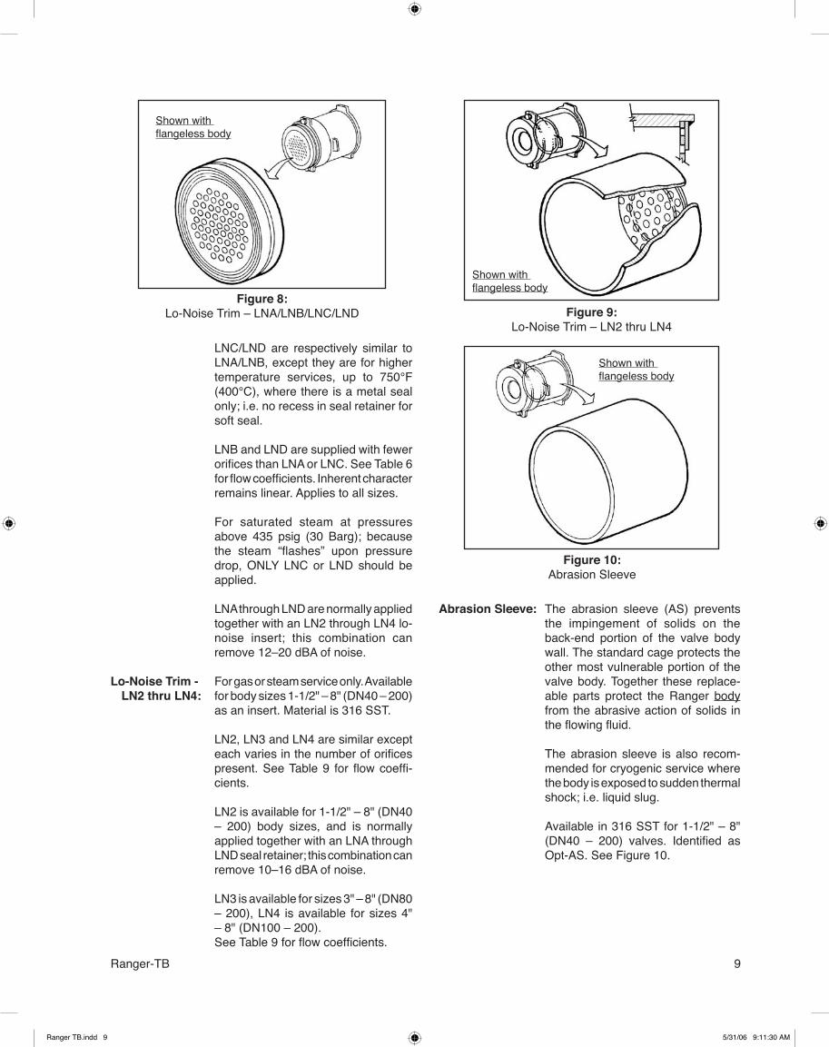
Lo-Noise Trim – LNA/LNB; LNC/LND:
Ranger TB.indd 8 5/31/06 9:11:29 AM
9Ranger-TB
Figure 8:Lo-Noise Trim – LNA/LNB/LNC/LND
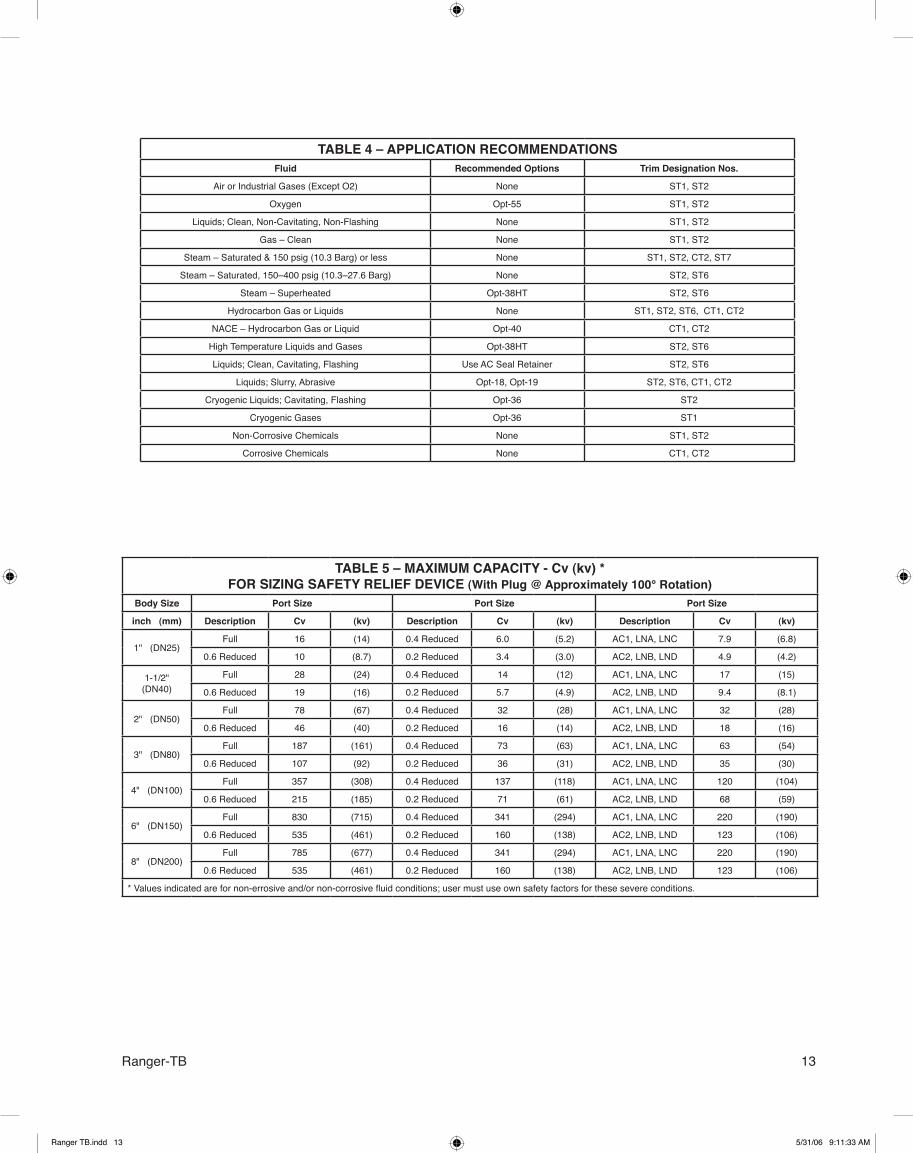
The abrasion sleeve (AS) prevents the impingement of solids on the back-end portion of the valve body wall. The standard cage protects the other most vulnerable portion of the valve body. Together these replace-able parts protect the Ranger body from the abrasive action of solids in the flowing fluid.
The abrasion sleeve is also recom-mended for cryogenic service where the body is exposed to sudden thermal shock; i.e. liquid slug.
Available in 316 SST for 1-1/2" – 8" (DN40 – 200) valves. Identified as Opt-AS. See Figure 10.
LNC/LND are respectively similar to LNA/LNB, except they are for higher temperature services, up to 750°F (400°C), where there is a metal seal only; i.e. no recess in seal retainer for soft seal.
LNB and LND are supplied with fewer orifices than LNA or LNC. See Table 6 for flow coefficients. Inherent character remains linear. Applies to all sizes.
For saturated steam at pressures above 435 psig (30 Barg); because the steam “flashes” upon pressure drop, ONLY LNC or LND should be applied.
LNA through LND are normally applied together with an LN2 through LN4 lo-noise insert; this combination can remove 12–20 dBA of noise.
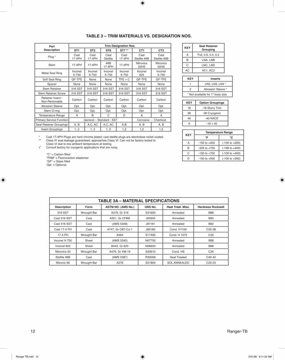
For gas or steam service only. Available for body sizes 1-1/2" – 8" (DN40 – 200) as an insert. Material is 316 SST.
LN2, LN3 and LN4 are similar except each varies in the number of orifices present. See Table 9 for flow coeffi-cients.
LN2 is available for 1-1/2" – 8" (DN40 – 200) body sizes, and is normally applied together with an LNA through LND seal retainer; this combination can remove 10–16 dBA of noise.
LN3 is available for sizes 3" – 8" (DN80 – 200), LN4 is available for sizes 4" – 8" (DN100 – 200). See Table 9 for flow coefficients.
Lo-Noise Trim - LN2 thru LN4:
Shown with flangeless body
Abrasion Sleeve:
Figure 9:Lo-Noise Trim – LN2 thru LN4
Figure 10:Abrasion Sleeve
Shown with flangeless body
Shown with flangeless body
Ranger TB.indd 9 5/31/06 9:11:30 AM

10 Ranger-TB
TABLE 1A – MATERIAL PRESSURE vs. TEMPERATURE RATINGSDUCTILE IRON per ANSI B16.42
Body MaterialEnd
Connection
English Units Metric Units
General ASTM Spec. No.Pressure Temperature Pressure Temperature
(psig) (°F) (Barg) (°C)
CastDuctile
Iron(DI)
A395
Flangeless,150# Flg. *
(PN20)
250 -20 to +100 17.2 -29 to +38235 200 16.2 94215 300 14.8 149200 400 13.8 205185 450 12.8 233170 500 11.8 260155 550 10.7 288140 600 9.7 316125 650 8.6 344
Flangeless,300# Flg.(PN50)
640 -20 to +100 44.1 -29 to +38600 200 41.4 94565 300 39.0 149525 400 36.2 205510 450 35.2 233495 500 34.2 260480 550 33.1 288465 600 32.1 316450 650 31.0 344
* Based upon CS pipe material.
TECHNICAL SPECIFICATIONS
TABLE 1B – MATERIAL PRESSURE vs. TEMPERATURE RATINGSCARBON STEEL PER ANSI B16.34
Body MaterialEnd
Connection
English Units Metric Units
General ASTM Spec. No. Pressure(psig)
Temperature(°F)
Pressure(Barg)
Temperature(°C)
CastCarbonSteel
A216,GR. WCB
Flanged orFlangeless150# Flg.(PN20)
285 -20 to +100 19.7 -29 to +38260 200 18.0 94230 300 15.9 149200 400 13.8 205185 450 12.8 233170 500 11.8 260155 550 10.7 288125 650 8.6 344110 700 7.6 37295 750 6.6 400
Flanged orFlangeless300# Flg.(PN50)
740 -20 to +100 51.1 -29 to +38675 200 46.6 94655 300 45.2 149635 400 43.8 205615 450 42.4 233600 500 41.4 260575 550 39.7 288535 650 36.9 344535 700 36.9 372505 750 34.8 400
Flanged orFlangeless600# Flg.(PN100)
*
1480 -20 to +100 102.1 -29 to +381350 200 93.1 941315 300 90.7 1491270 400 87.6 2051235 450 85.2 2331200 500 82.8 2601145 550 79.0 2881075 650 74.2 3441010 750 69.7 400
* Not available for 4", 6" and 8" (DN 100, 150, 200) body sizes with integral flanges. Not available “flangeless” for the 8" (DN200) body size.
Ranger TB.indd 10 5/31/06 9:11:31 AM

11Ranger-TB
TABLE 1C – MATERIAL PRESSURE vs. TEMPERATURE RATINGSSTAINLESS STEEL PER ANSI B16.34
Body Material EndConnction
English Units Metric Units
General ASTM Spec. No. Pressure(psig)
Temperature(°F)
Pressure(Barg)
Temperature(°C)
CastStainless
Steel
A351,Gr. CF8M
Flanged orFlangeless150# Flg.(PN20)
275 * -325 to +100 19.0 * -198 to +38235 200 16.2 94215 300 14.8 149195 400 13.5 205180 450 12.4 233170 500 11.8 260155 550 10.7 288125 650 8.6 34495 750 6.6 400
CastStainless
Steel
A351,Gr. CF8M
Flanged orFlangeless300# Flg.
(PN50
720 * -325 to +100 50.0 * -198 to +38620 200 42.8 94560 300 38.7 149515 400 35.6 205495 450 34.1 233480 500 33.1 260465 550 32.1 288445 650 30.7 344430 700 30.0 372425 750 29.3 400
Flanged orFlangeless600# Flg.(PN100)
**
1440 -20 to +100 99.3 -29 to +381240 200 85.6 941120 300 77.3 1491025 400 70.7 205990 450 68.3 233955 500 65.9 260925 550 63.8 288890 650 61.4 344870 700 60.0 372855 750 58.9 400
* PMax for Cryogenic Opt-36 down to -325°F (-198°C).** Not available for 4", 6" and 8" (DN100, 150, 200) body sizes with integral flanges. Not available “flangeless” for the 8" (DN200) body size.
TABLE 2 – MAXIMUM PRESSURE DROP CAPABILITYBody Bench Set
Rangepsid
(bard)
With Positioner 1 Without Positioner 2 With I/P Transducer 3
Trim Trim Trim
Mat'l. SizeStdpsid
(bard)
AC *psid
(bard)
Std.psid
(bard)
Chem **psid
(bard)
Std.psid
(bard)
AC *psid
(bard)
Chem **psid
(bard)
Std. psid
(bard)
AC *psid
(bard)
Chem **psid
(bard)
CS orSST
1"(DN25)
5-15(0.34-1.03)
1400(96.5)
600(41.4)
600(41.4)
700(48.3)
600(41.4)
600(41.4)
600(41.4)
600(41.4)
400(27.6)
400(27.6)
1-1/2"(DN40)
5-15(0.34-1.03)
1200(82.8)
600(41.4)
600(41.4)
600(41.4)
600(41.4)
600(41.4)
600(41.4)
600(41.4)
400(27.6)
400(27.6)
DI, CSor
SST
2"(DN50)
5-15(0.34-1.03)
600(41.4)
600(41.4)
600(41.4)
300(20.7)
400(27.6)
400(27.6)
300(20.7)
300(20.7)
300(20.7)
200(13.8)
3"(DN80)
5-13(0.34-0.90)
600(41.4)
600(41.4)
600(41.4)
300(20.7)
600(41.4)
600(41.4)
300(20.7)
400(27.6)
400(27.6)
200(13.8)
4"(DN100)
5-13(0.34-0.90) N/A N/A N/A N/A 200
(13.8)200
(13.8)200
(13.8)150
(10.3)150
(10.3)150
(10.3)10-26
(0.69-1.79)600
(41.4)600
(41.4)300
(20.7)200
(13.8)300
(20.7)300
(20.7)150
(10.3)6", 8"
(DN150,200)10-26
(0.69-1.79)300
(20.7)300
(20.7)200
(13.8)150
(10.3)200
(13.8)200
(13.8)150
(10.3)
DI 1",1-1/2"(DN25, 40)
5-15(0.34-1.03)
600(41.4)
600(41.4)
600(41.4)
600(41.4)
600(41.4)
600(41.4)
600(41.4)
400(27.6)
400(27.6)
400(27.6)
FLOW DIRECTION Std. Rev. Rev. Std. Both Rev. Both Both Rev. Both1 Use the “With Positioner” Max ∆P values for use in ON-OFF service.2 3-15 psig (0.21-1.03 Barg) SIG directly to actuator.3 1-17 psig (0.07-1.17 Barg) OUTPUT LOAD directly to actuator (no positioner);
4-20mA INPUT SIG. Tight shutoff may NOT be attained.* “AC” = “anti-cavitation” seal retainer. With a 3-15 psig (0.21-1.03 Barg) SIG, requires a 1:2 air supply booster.
** “Chem Trim” is defined as any trim that uses a Stellite 6B plug or a Nitronic 50HS Stem; includes trim designation nos. CT1 & CT2.
NOTES: 1. The above pressure drops apply to the valve as a “unit”, including all
seal retainers and lo-noise inserts.2. When “Chem Trim” is applied with an AC seal retainer, the lower of the two
“maximum pressure drop” values is to be the upper limit.
Ranger TB.indd 11 5/31/06 9:11:32 AM
12 Ranger-TB
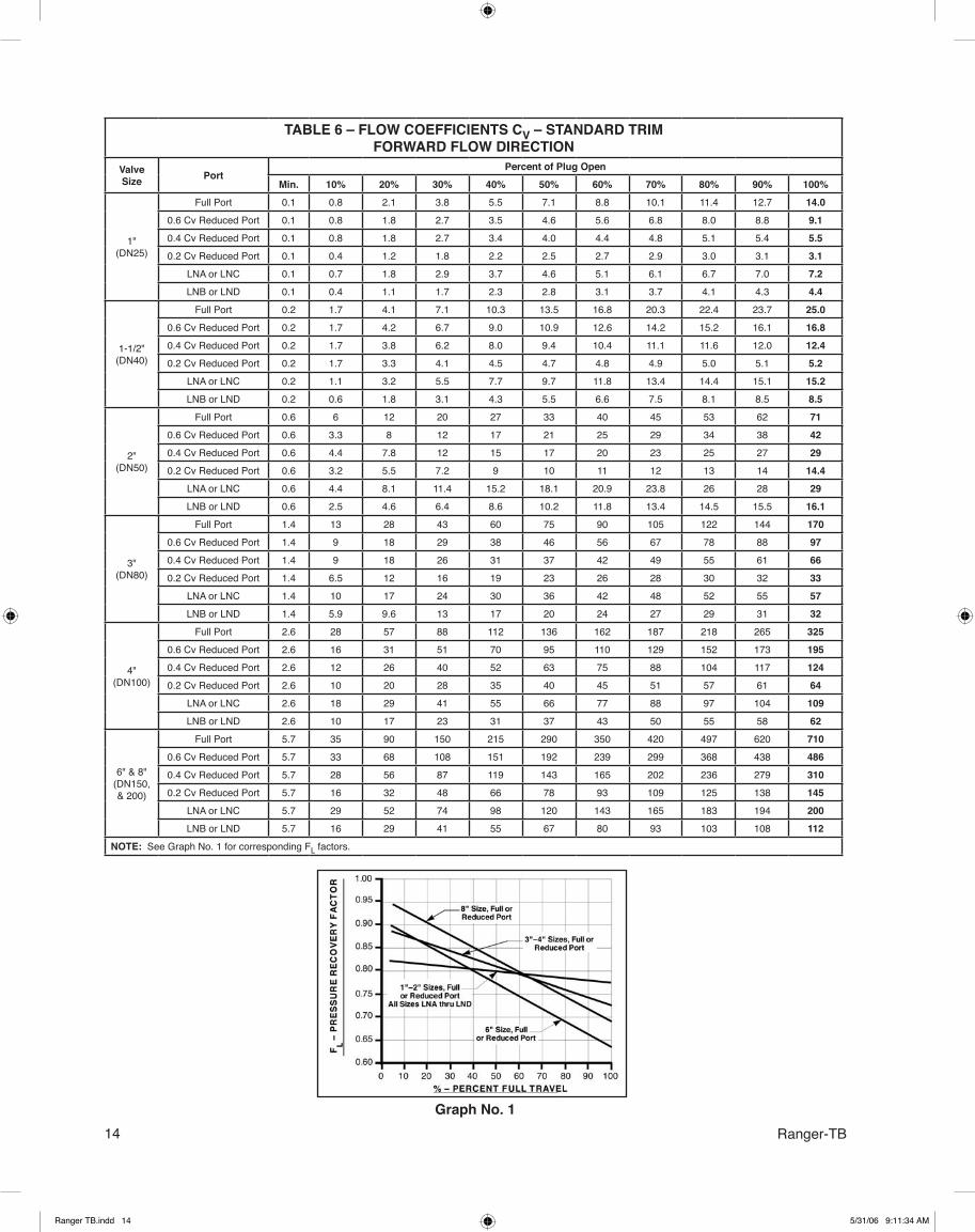
TABLE 3 – TRIM MATERIALS VS. DESIGNATION NOS.
KEY Seal RetainerGrouping
A Full, 0.6, 0.4, 0.2
B LNA, LNB
C LNC, LND
AC AC1, AC2
KEY Inserts1 LN2, LN3, LN4 *
2 Abrasion Sleeve *
* Not available for 1" body size.
PartDescription
Trim Designation Nos.ST1 ST2 ST6 ST7 ** CT1 CT2
Plug * Cast17-4PH
Cast17-4PH
CastStellite
Cast17-4PH
CastStellite #6B
CastStellite #6B
Stem 17-4PH 17-4PH #6B17-4PH 17-4PH Nitronics
50HSNitronics
50HS
Metal Seal Ring InconelX-750
InconelX-750
InconelX-750
InconelX-750
Inconel625
InconelX-750
Soft Seal Ring GF-TFE None None TFE + C GF-TFE GF-TFESpacer None None None None None None
Stem Retainer 316 SST 316 SST 316 SST 316 SST 316 SST 316 SSTStem Retainer Screw 316 SST 316 SST 316 SST 316 SST 316 SST 316 SST
Retainer Insert - Non-Removable Carbon Carbon Carbon Carbon Carbon Carbon
Abrasion Sleeve Opt. Opt. Opt. Opt. Opt. Opt.Stem O-ring Opt. Opt. Opt. Opt. Opt. Opt.
Temperature Range A B C D A APrimary Service Function General – Standard - SST Corrosive — ChemicalSeal Retainer Groupings A, B A,C, AC A,C, AC A,B A, B A, B
Insert Groupings 1, 2 1, 2 1, 2 1,2 1,2 1,2
KEYTemperature Range°F °C
A -150 to +400 (-100 to +205)
B -325 to +750 (-198 to +400)
C -150 to +750 (-100 to +400)
D -150 to +500 (-100 to +260)
KEY Option Groupings18 -18 Slurry Trim
36 -36 Cryogenic
40 -40 NACE
A -18 + 40
* Cast 17-4PH Plugs are hard chrome plated; cast stellite plugs are electroless nickel coated.** Class IV seat leakage guaranteed; approaches Class VI. Can not be factory tested to Class VI due to low ambient temperature at testing.√ Consult factory for cryogenic applications that are noisy.
“C” = Carbon filled“FKM” = Fluorocarbon elastomer“GF” = Glass filledOpt. = Optional
TABLE 3A – MATERIAL SPECIFICATIONSDescription Form ASTM NO. (AMS No.) UNS No. Heat Treat- Misc. Hardness Rockwell
316 SST Wrought Bar A479, Gr 316 S31600 Annealed B88
Cast 316 SST Cast A351, Gr CF8M J92900 Annealed B85
Cast 416 SST Cast (AMS 5349) J91161 Annealed B82
Cast 17-4 PH Cast A747, Gr CB7-Cu-1 J92180 Cond. H1100 C35-38
17-4 PH Wrought Bar A564 S17400 Cond. H 1075 C35
Inconel X-750 Sheet (AMS 5542) N07750 Annealed B88
Inconel 625 Sheet B443, Gr 625 N06625 Annealed B88
Nitronics 50 Wrought Bar A479, Gr XM-19 S20910 Cond. HS C35
Stellite #6B Cast (AMS 5387) R30006 Heat Treated C40-42
Nitronic 60 Wrought Bar A276 S21800 SOL ANNEALED C22-23
Ranger TB.indd 12 5/31/06 9:11:32 AM
13Ranger-TB
TABLE 5 – MAXIMUM CAPACITY - Cv (kv) *FOR SIZING SAFETY RELIEF DEVICE (With Plug @ Approximately 100° Rotation)
Body Size Port Size Port Size Port Size
inch (mm) Description Cv (kv) Description Cv (kv) Description Cv (kv)
1" (DN25)Full 16 (14) 0.4 Reduced 6.0 (5.2) AC1, LNA, LNC 7.9 (6.8)
0.6 Reduced 10 (8.7) 0.2 Reduced 3.4 (3.0) AC2, LNB, LND 4.9 (4.2)
1-1/2" (DN40)
Full 28 (24) 0.4 Reduced 14 (12) AC1, LNA, LNC 17 (15)
0.6 Reduced 19 (16) 0.2 Reduced 5.7 (4.9) AC2, LNB, LND 9.4 (8.1)
2" (DN50)Full 78 (67) 0.4 Reduced 32 (28) AC1, LNA, LNC 32 (28)
0.6 Reduced 46 (40) 0.2 Reduced 16 (14) AC2, LNB, LND 18 (16)
3" (DN80)Full 187 (161) 0.4 Reduced 73 (63) AC1, LNA, LNC 63 (54)
0.6 Reduced 107 (92) 0.2 Reduced 36 (31) AC2, LNB, LND 35 (30)
4" (DN100)Full 357 (308) 0.4 Reduced 137 (118) AC1, LNA, LNC 120 (104)
0.6 Reduced 215 (185) 0.2 Reduced 71 (61) AC2, LNB, LND 68 (59)
6" (DN150)Full 830 (715) 0.4 Reduced 341 (294) AC1, LNA, LNC 220 (190)
0.6 Reduced 535 (461) 0.2 Reduced 160 (138) AC2, LNB, LND 123 (106)
8" (DN200)Full 785 (677) 0.4 Reduced 341 (294) AC1, LNA, LNC 220 (190)
0.6 Reduced 535 (461) 0.2 Reduced 160 (138) AC2, LNB, LND 123 (106)
* Values indicated are for non-errosive and/or non-corrosive fluid conditions; user must use own safety factors for these severe conditions.
TABLE 4 – APPLICATION RECOMMENDATIONSFluid Recommended Options Trim Designation Nos.
Air or Industrial Gases (Except O2) None ST1, ST2
Oxygen Opt-55 ST1, ST2
Liquids; Clean, Non-Cavitating, Non-Flashing None ST1, ST2
Gas – Clean None ST1, ST2
Steam – Saturated & 150 psig (10.3 Barg) or less None ST1, ST2, CT2, ST7
Steam – Saturated, 150–400 psig (10.3–27.6 Barg) None ST2, ST6
Steam – Superheated Opt-38HT ST2, ST6
Hydrocarbon Gas or Liquids None ST1, ST2, ST6, CT1, CT2
NACE – Hydrocarbon Gas or Liquid Opt-40 CT1, CT2
High Temperature Liquids and Gases Opt-38HT ST2, ST6
Liquids; Clean, Cavitating, Flashing Use AC Seal Retainer ST2, ST6
Liquids; Slurry, Abrasive Opt-18, Opt-19 ST2, ST6, CT1, CT2
Cryogenic Liquids; Cavitating, Flashing Opt-36 ST2
Cryogenic Gases Opt-36 ST1
Non-Corrosive Chemicals None ST1, ST2
Corrosive Chemicals None CT1, CT2
Ranger TB.indd 13 5/31/06 9:11:33 AM
14 Ranger-TBGraph No. 1
TABLE 6 – FLOW COEFFICIENTS CV – STANDARD TRIMFORWARD FLOW DIRECTION
ValveSize Port
Percent of Plug OpenMin. 10% 20% 30% 40% 50% 60% 70% 80% 90% 100%
1"(DN25)
Full Port 0.1 0.8 2.1 3.8 5.5 7.1 8.8 10.1 11.4 12.7 14.00.6 Cv Reduced Port 0.1 0.8 1.8 2.7 3.5 4.6 5.6 6.8 8.0 8.8 9.10.4 Cv Reduced Port 0.1 0.8 1.8 2.7 3.4 4.0 4.4 4.8 5.1 5.4 5.50.2 Cv Reduced Port 0.1 0.4 1.2 1.8 2.2 2.5 2.7 2.9 3.0 3.1 3.1
LNA or LNC 0.1 0.7 1.8 2.9 3.7 4.6 5.1 6.1 6.7 7.0 7.2LNB or LND 0.1 0.4 1.1 1.7 2.3 2.8 3.1 3.7 4.1 4.3 4.4
1-1/2"(DN40)
Full Port 0.2 1.7 4.1 7.1 10.3 13.5 16.8 20.3 22.4 23.7 25.00.6 Cv Reduced Port 0.2 1.7 4.2 6.7 9.0 10.9 12.6 14.2 15.2 16.1 16.80.4 Cv Reduced Port 0.2 1.7 3.8 6.2 8.0 9.4 10.4 11.1 11.6 12.0 12.40.2 Cv Reduced Port 0.2 1.7 3.3 4.1 4.5 4.7 4.8 4.9 5.0 5.1 5.2
LNA or LNC 0.2 1.1 3.2 5.5 7.7 9.7 11.8 13.4 14.4 15.1 15.2LNB or LND 0.2 0.6 1.8 3.1 4.3 5.5 6.6 7.5 8.1 8.5 8.5
2"(DN50)
Full Port 0.6 6 12 20 27 33 40 45 53 62 710.6 Cv Reduced Port 0.6 3.3 8 12 17 21 25 29 34 38 420.4 Cv Reduced Port 0.6 4.4 7.8 12 15 17 20 23 25 27 290.2 Cv Reduced Port 0.6 3.2 5.5 7.2 9 10 11 12 13 14 14.4
LNA or LNC 0.6 4.4 8.1 11.4 15.2 18.1 20.9 23.8 26 28 29LNB or LND 0.6 2.5 4.6 6.4 8.6 10.2 11.8 13.4 14.5 15.5 16.1
3"(DN80)
Full Port 1.4 13 28 43 60 75 90 105 122 144 1700.6 Cv Reduced Port 1.4 9 18 29 38 46 56 67 78 88 970.4 Cv Reduced Port 1.4 9 18 26 31 37 42 49 55 61 660.2 Cv Reduced Port 1.4 6.5 12 16 19 23 26 28 30 32 33
LNA or LNC 1.4 10 17 24 30 36 42 48 52 55 57LNB or LND 1.4 5.9 9.6 13 17 20 24 27 29 31 32
4"(DN100)
Full Port 2.6 28 57 88 112 136 162 187 218 265 3250.6 Cv Reduced Port 2.6 16 31 51 70 95 110 129 152 173 1950.4 Cv Reduced Port 2.6 12 26 40 52 63 75 88 104 117 1240.2 Cv Reduced Port 2.6 10 20 28 35 40 45 51 57 61 64
LNA or LNC 2.6 18 29 41 55 66 77 88 97 104 109LNB or LND 2.6 10 17 23 31 37 43 50 55 58 62
6" & 8"(DN150,& 200)
Full Port 5.7 35 90 150 215 290 350 420 497 620 7100.6 Cv Reduced Port 5.7 33 68 108 151 192 239 299 368 438 4860.4 Cv Reduced Port 5.7 28 56 87 119 143 165 202 236 279 3100.2 Cv Reduced Port 5.7 16 32 48 66 78 93 109 125 138 145
LNA or LNC 5.7 29 52 74 98 120 143 165 183 194 200LNB or LND 5.7 16 29 41 55 67 80 93 103 108 112
NOTE: See Graph No. 1 for corresponding FL factors.
Ranger TB.indd 14 5/31/06 9:11:34 AM
15Ranger-TB
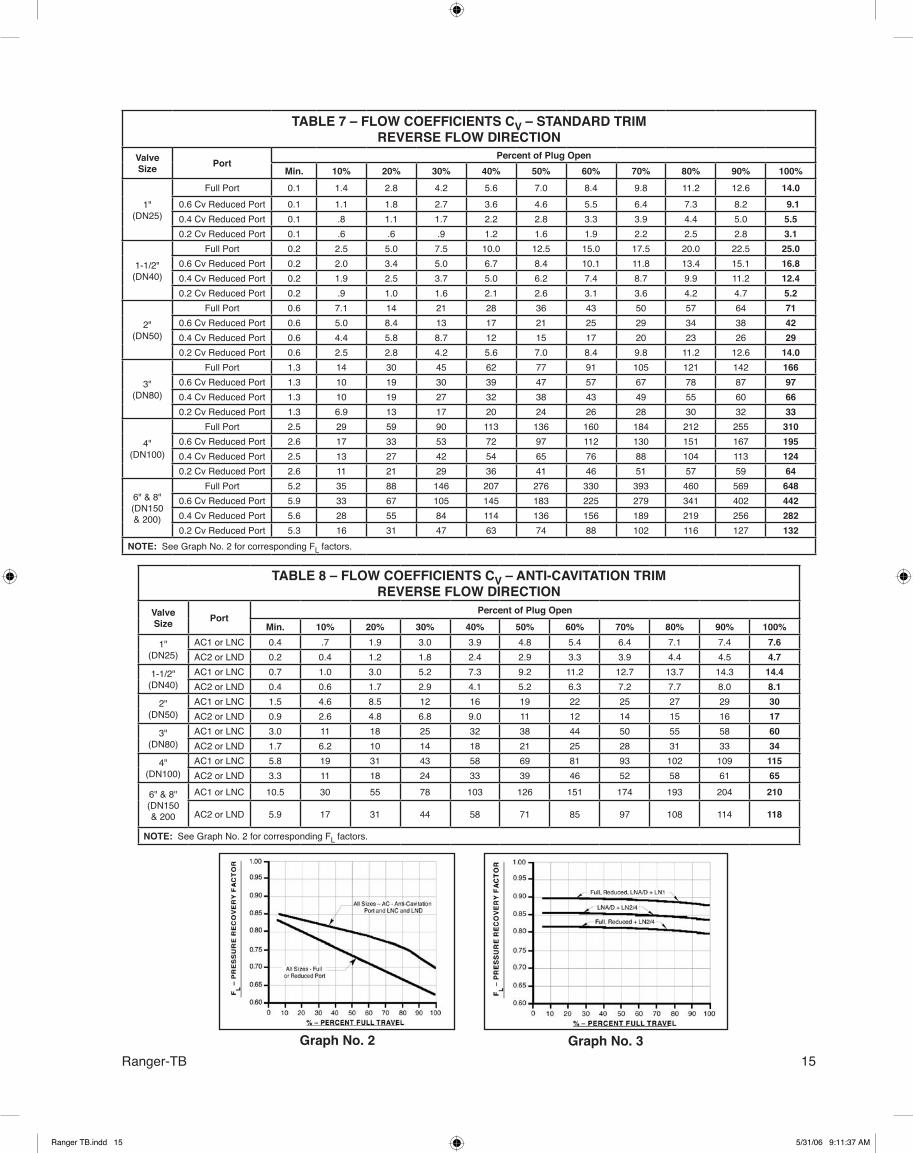
TABLE 8 – FLOW COEFFICIENTS CV – ANTI-CAVITATION TRIMREVERSE FLOW DIRECTION
ValveSize Port
Percent of Plug Open
Min. 10% 20% 30% 40% 50% 60% 70% 80% 90% 100%
1"(DN25)
AC1 or LNC 0.4 .7 1.9 3.0 3.9 4.8 5.4 6.4 7.1 7.4 7.6AC2 or LND 0.2 0.4 1.2 1.8 2.4 2.9 3.3 3.9 4.4 4.5 4.7
1-1/2"(DN40)
AC1 or LNC 0.7 1.0 3.0 5.2 7.3 9.2 11.2 12.7 13.7 14.3 14.4AC2 or LND 0.4 0.6 1.7 2.9 4.1 5.2 6.3 7.2 7.7 8.0 8.1
2"(DN50)
AC1 or LNC 1.5 4.6 8.5 12 16 19 22 25 27 29 30AC2 or LND 0.9 2.6 4.8 6.8 9.0 11 12 14 15 16 17
3"(DN80)
AC1 or LNC 3.0 11 18 25 32 38 44 50 55 58 60AC2 or LND 1.7 6.2 10 14 18 21 25 28 31 33 34
4"(DN100)
AC1 or LNC 5.8 19 31 43 58 69 81 93 102 109 115AC2 or LND 3.3 11 18 24 33 39 46 52 58 61 65
6" & 8"(DN150 & 200
AC1 or LNC 10.5 30 55 78 103 126 151 174 193 204 210
AC2 or LND 5.9 17 31 44 58 71 85 97 108 114 118
NOTE: See Graph No. 2 for corresponding FL factors.
TABLE 7 – FLOW COEFFICIENTS CV – STANDARD TRIMREVERSE FLOW DIRECTION
ValveSize Port
Percent of Plug OpenMin. 10% 20% 30% 40% 50% 60% 70% 80% 90% 100%
1"(DN25)
Full Port 0.1 1.4 2.8 4.2 5.6 7.0 8.4 9.8 11.2 12.6 14.00.6 Cv Reduced Port 0.1 1.1 1.8 2.7 3.6 4.6 5.5 6.4 7.3 8.2 9.10.4 Cv Reduced Port 0.1 .8 1.1 1.7 2.2 2.8 3.3 3.9 4.4 5.0 5.50.2 Cv Reduced Port 0.1 .6 .6 .9 1.2 1.6 1.9 2.2 2.5 2.8 3.1
1-1/2"(DN40)
Full Port 0.2 2.5 5.0 7.5 10.0 12.5 15.0 17.5 20.0 22.5 25.00.6 Cv Reduced Port 0.2 2.0 3.4 5.0 6.7 8.4 10.1 11.8 13.4 15.1 16.80.4 Cv Reduced Port 0.2 1.9 2.5 3.7 5.0 6.2 7.4 8.7 9.9 11.2 12.40.2 Cv Reduced Port 0.2 .9 1.0 1.6 2.1 2.6 3.1 3.6 4.2 4.7 5.2
2"(DN50)
Full Port 0.6 7.1 14 21 28 36 43 50 57 64 710.6 Cv Reduced Port 0.6 5.0 8.4 13 17 21 25 29 34 38 420.4 Cv Reduced Port 0.6 4.4 5.8 8.7 12 15 17 20 23 26 290.2 Cv Reduced Port 0.6 2.5 2.8 4.2 5.6 7.0 8.4 9.8 11.2 12.6 14.0
3"(DN80)
Full Port 1.3 14 30 45 62 77 91 105 121 142 1660.6 Cv Reduced Port 1.3 10 19 30 39 47 57 67 78 87 970.4 Cv Reduced Port 1.3 10 19 27 32 38 43 49 55 60 660.2 Cv Reduced Port 1.3 6.9 13 17 20 24 26 28 30 32 33
4"(DN100)
Full Port 2.5 29 59 90 113 136 160 184 212 255 3100.6 Cv Reduced Port 2.6 17 33 53 72 97 112 130 151 167 1950.4 Cv Reduced Port 2.5 13 27 42 54 65 76 88 104 113 1240.2 Cv Reduced Port 2.6 11 21 29 36 41 46 51 57 59 64
6" & 8"(DN150& 200)
Full Port 5.2 35 88 146 207 276 330 393 460 569 6480.6 Cv Reduced Port 5.9 33 67 105 145 183 225 279 341 402 4420.4 Cv Reduced Port 5.6 28 55 84 114 136 156 189 219 256 2820.2 Cv Reduced Port 5.3 16 31 47 63 74 88 102 116 127 132
NOTE: See Graph No. 2 for corresponding FL factors.
Graph No. 2 Graph No. 3
Ranger TB.indd 15 5/31/06 9:11:37 AM

16 Ranger-TB
TABLE 9 – FLOW COEFFICIENTS CV – LO-NOISE TRIMSTD (FORWARD) FLOW DIRECTION
ValveSize
TrimInsert Port
Percent of Plug TravelMin. 10% 20% 30% 40% 50% 60% 70% 80% 90% 100%
1-1/2"(DN40) LN2
Full 0.2 1.7 4.0 6.7 9.2 11.2 12.9 14.2 14.9 15.3 15.60.6 Reduced 0.3 1.7 4.1 6.4 8.2 9.6 10.7 11.6 12.1 12.5 12.90.4 Reduced 0.3 1.7 3.7 5.9 7.4 8.5 9.2 9.7 10.0 10.3 10.50.2 Reduced 0.3 1.7 3.3 4.0 4.4 4.6 4.7 4.8 4.9 4.9 5.0LNA or LNC 0.4 1.1 3.1 5.3 7.2 8.7 10.2 11.1 11.7 12.0 12.1LNB or LND 0.3 0.6 1.8 3.0 4.2 5.3 6.3 7.1 7.5 7.8 7.9
2"(DN50) LN2
Full 0.3 5.8 10.8 15.6 18.3 19.9 21.2 21.9 22.6 23.2 23.60.6 Reduced 0.4 3.3 7.6 10.8 14.1 16.1 17.7 18.9 20.1 20.9 21.50.4 Reduced 0.5 4.3 7.4 10.8 12.9 14.1 15.6 16.9 17.7 18.3 18.90.2 Reduced 0.8 3.2 5.4 6.9 8.5 9.3 10.1 10.8 11.5 12.2 12.5LNA or LNC 0.6 4.3 7.7 10.4 13.0 14.6 16.0 17.2 17.9 18.5 18.8LNB or LND 0.5 2.5 4.5 6.2 8.1 9.4 10.7 11.8 12.5 13.2 13.5
3"(DN80)
LN2
Full 0.8 13 26 36 44 50 53 56 58 60 620.6 Reduced 1.1 9 17 27 33 38 43 47 50 53 550.4 Reduced 1.3 9 17 24 28 32 35 39 42 45 470.2 Reduced 2.0 6.5 12 16 18 22 24 26 27 29 30
LN3
Full 0.5 12 24 31 36 39 40 41 42 43 440.6 Reduced 0.8 8.8 17 24 29 32 35 37 39 40 410.4 Reduced 1.1 8.8 17 23 26 29 31 33 35 36 370.2 Reduced 1.8 6.4 12 15 18 20 23 24 25 26 27
LN2LNA or LNC 1.4 10 17 22 28 32 35 39 41 42 43LNB or LND 1.2 5.9 9.5 13 17 19 22 25 27 28 29
LN3LNA or LNC 1.2 10 16 21 25 28 31 33 34 35 35LNB or LND 1.0 5.8 9.4 13 16 19 21 23 25 26 26
4"(DN100)
LN2
Full 1.1 27 48 63 70 75 79 81 83 85 870.6 Reduced 1.6 16 29 44 55 65 70 74 77 80 820.4 Reduced 2.1 12 25 37 45 52 58 63 68 71 730.2 Reduced 3.5 10 20 27 33 37 40 44 48 50 52
LN3
Full 0.8 26 43 53 57 59 61 62 63 64 650.6 Reduced 1.3 16 28 40 48 54 57 59 61 62 630.4 Reduced 1.7 12 24 34 41 46 50 53 56 57 580.2 Reduced 3.1 10 19 26 31 34 37 40 43 45 46
LN4
Full 1.3 27 51 70 80 87 93 97 101 105 1080.6 Reduced 2.0 16 30 47 60 73 79 85 91 95 980.4 Reduced 2.4 12 25 38 47 55 63 70 77 82 840.2 Reduced 3.7 10 20 27 33 38 42 47 51 54 56
LN2LNA or LNC 2.3 18 28 37 47 53 58 63 66 68 69LNB or LND 2.0 10 16 22 29 34 39 44 47 49 51
LN3LNA or LNC 1.9 17 27 35 42 47 50 53 55 56 56LNB or LND 1.8 10 16 22 28 32 36 40 42 44 45
LN4LNA or LNC 2.6 18 29 38 50 57 64 70 74 77 79LNB or LND 2.2 10 16 23 30 35 41 46 49 52 54
6" & 8"(DN150& 200)
LN2
Full 2.4 34 82 120 146 165 174 181 186 190 1930.6 Reduced 3.7 33 64 95 121 139 153 166 176 182 1850.4 Reduced 4.8 28 54 80 102 116 127 142 153 163 1680.2 Reduced 7.8 16 32 47 63 73 84 96 106 114 117
LN3
Full 1.6 34 75 100 113 121 124 127 128 130 1310.6 Reduced 2.6 32 61 84 100 109 116 122 125 127 1280.4 Reduced 3.5 27 52 73 89 97 104 111 116 120 1220.2 Reduced 6.5 16 31 45 59 67 76 84 91 96 98
LN4
Full 3.0 35 85 129 163 190 204 215 224 233 2370.6 Reduced 4.5 33 66 99 129 152 173 192 207 218 2230.4 Reduced 5.6 28 55 82 108 124 138 157 172 187 1950.2 Reduced 8.4 16 32 47 64 74 87 100 112 121 126
LN2LNA or LNC 4.7 28 51 69 88 103 117 127 135 139 141LNB or LND 3.9 16 29 41 53 64 75 84 91 95 97
LN3LNA or LNC 3.7 28 49 65 79 89 98 104 108 110 111LNB or LND 3.4 16 29 40 51 60 69 76 81 84 86
LN4LNA or LNC 5.2 28 51 71 91 108 125 138 148 153 156LNB or LND 4.1 16 29 41 54 65 76 87 95 100 102
NOTES: 1. See Graph No. 3 for corresponding FL factors. 2. See Table 5 for Cv's of LNA, LNB, LNC or LND in std. flow direction with NO insert.
Ranger TB.indd 16 5/31/06 9:11:39 AM
17Ranger-TB
Bypass for 73 P/P positioner.764 P/PD pressure controller.Lockup valve.Position transmitter.
Model 991 positioners, microswitches are standard, unit is enclosed in the positioner housing.
All other brands and types are consult factory.
MOUNTED ACCESSORY SPECIFICATIONS
General. Mounted to arm housing. All feedback linkage is enclosed and not exposed directly to elements.
P/P Pneumatic. Model 73. Adjustable zero only. Analog signal only.
P/P Pneumatic. Model 9540R. Ad-justable zero, gain, damping, or stroke. Analog signal only.
I/P Electro-Pneumatic. 991 and PS2. The 991 is digital, Hart, Profibus, and Fieldbus compatible, and PS2 is avail-able in Hart, Fieldbus, Profibus. LCD display is standard on the 991 and the PS2 positioners.
Standard instrument air tubing is “Im-polene” thermo-plastic tubing with brass fittings.
Optional copper tubing with brass fittings, or SST tube and fittings.
Model 5200P instrument air supply regulator. Use with positioners. Bracket mounted to actuator casing. Supplied with gauge for P/P positioners; no gauge with I/P positioner. See technical bulletin 5200P-TB.
Standard Brass: Available in standard weather-proof model. Brass body, 1/4" female NPT connections. Nipple mounted to actuator casing. 120 VAC, 60 Hz power supply, CSA Approved Class 3221-01, NEMA 2,3,3S,4,4X.
X-Proof or SST construction: Consult Factory.
Standard installation vents actuator and drives valve to fail-safe position upon loss of electrical power.
Consult factory for 230/1/50, or 24 VDC power supplies, or intrinsically safe (IS) service.Consult Factory
FM, CSA approved NEMA 4X Cl 1, Div 1 and Cl 1, Div 2
Positioners:
Air Tubing:
Airset:
Solenoid Valve:
Transducers
Other Accessories:
Limit Switches:
Ranger TB.indd 17 5/31/06 9:11:39 AM
18 Ranger-TB
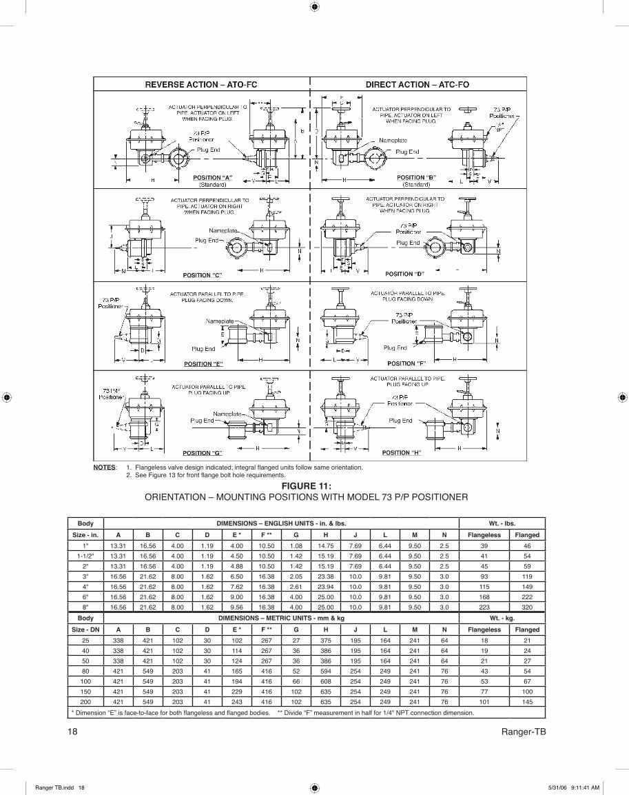
Body DIMENSIONS – ENGLISH UNITS - in. & lbs. Wt. - lbs.Size - in. A B C D E * F ** G H J L M N Flangeless Flanged
1" 13.31 16.56 4.00 1.19 4.00 10.50 1.08 14.75 7.69 6.44 9.50 2.5 39 461-1/2" 13.31 16.56 4.00 1.19 4.50 10.50 1.42 15.19 7.69 6.44 9.50 2.5 41 54
2" 13.31 16.56 4.00 1.19 4.88 10.50 1.42 15.19 7.69 6.44 9.50 2.5 45 593" 16.56 21.62 8.00 1.62 6.50 16.38 2.05 23.38 10.0 9.81 9.50 3.0 93 1194" 16.56 21.62 8.00 1.62 7.62 16.38 2.61 23.94 10.0 9.81 9.50 3.0 115 1496" 16.56 21.62 8.00 1.62 9.00 16.38 4.00 25.00 10.0 9.81 9.50 3.0 168 2228" 16.56 21.62 8.00 1.62 9.56 16.38 4.00 25.00 10.0 9.81 9.50 3.0 223 320
Body DIMENSIONS – METRIC UNITS - mm & kg Wt. - kg.Size - DN A B C D E * F ** G H J L M N Flangeless Flanged
25 338 421 102 30 102 267 27 375 195 164 241 64 18 2140 338 421 102 30 114 267 36 386 195 164 241 64 19 2450 338 421 102 30 124 267 36 386 195 164 241 64 21 2780 421 549 203 41 165 416 52 594 254 249 241 76 43 54
100 421 549 203 41 194 416 66 608 254 249 241 76 53 67150 421 549 203 41 229 416 102 635 254 249 241 76 77 100200 421 549 203 41 243 416 102 635 254 249 241 76 101 145
* Dimension “E” is face-to-face for both flangeless and flanged bodies. ** Divide “F” measurement in half for 1/4" NPT connection dimension.
FIGURE 11:ORIENTATION – MOUNTING POSITIONS WITH MODEL 73 P/P POSITIONER
NOTES: 1. Flangeless valve design indicated; integral flanged units follow same orientation. 2. See Figure 13 for front flange bolt hole requirements.
Ranger TB.indd 18 5/31/06 9:11:41 AM
19Ranger-TB
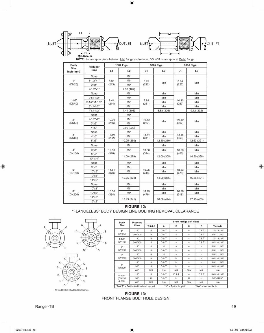
BodySize
inch (mm)
ReducerSize
150# Flgs. 300# Flgs. 600# Flgs.
L1 L2 L1 L2 L1 L2
1"(DN25)
None8.38(213)
Min8.75(222) Min 8.94
(227) Min1-1/2"x1" Min
2"x1" Min2-1/2"x1" 7.38 (187)
1-1/2"(DN40)
None
8.44(214)
Min
9.88(251)
Min
10.12(257)
Min2"x1-1/2" Min Min Min
2-1/2"x1-1/2" Min Min Min3"x1-1/2" Min Min Min4"x1-1/2" 7.44 (198) 8.88 (226) 9.12 (232)
2"(DN50)
None10.06(256)
Min10.13(257) Min 10.50
(267) Min2-1/2"x2" Min
3"x2" Min4"x2" 9.00 (229)
3"(DN80)
None11.50(292)
Min13.44(341)
Min13.88(353)
Min4"x3" Min Min Min6"x3" 10.25 (260) 12.19 (310) 12.63 (321)
4"(DN100)
None12.50(318)
Min13.56(344)
Min16.00(406)
Min6"x4" Min Min Min8"x4"
11.00 (279) 12.00 (305) 14.50 (368)10" x 4"
6"(DN150)
None
14.81(376)
Min
16.25(413)
Min
18.63(473)
Min8"x6" Min Min Min
10"x6" Min Min Min12"x6"
12.75 (324) 14.00 (356) 16.56 (421)14"x6"
8"(DN200)
None
15.50(394)
Min
18.75(476)
Min
20.38(518)
Min10"x8" Min Min Min12"x8" Min Min Min14"x8"
13.43 (341) 16.68 (424) 17.93 (455)16"x8"
BodySize
PressureClass
Front Flange Bolt Holes
Total # A B C D Threads
1"(DN25)
150 4 D & T – – D & T 1/2"-13UNC300/600 4 D & T – – D & T 5/8"-11UNC
1-1/2"(DN40)
150 4 D & T – – D & T 1/2"-13UNC300/600 4 D & T – – D & T 3/4"-10UNC
2"(DN50)
150 4 H – – H 5/8"-11UNC300/600 8 D & T H – H 5/8"-11UNC
3"(DN80)
150 4 H – – H 5/8"-11UNC300/600 8 D & T H – H 3/4"-10UNC
4"(DN100)
150 8 D & T H – H 5/8"-11UNC300 8 D & T H – H 3/4"-10UNC600 N/A N/A N/A N/A N/A N/A
6" & 8"(DN150& 200)
150 8 D & T D & T – D & T 3/4"-10UNC300 12 D & T H H H 7/8"-9UNC600 N/A N/A N/A N/A N/A N/A
“D & T” = Bolt hole drilled and tapped “H” = Bolt hole, plain “N/A” = Not available
NOTE: Locate spool piece between Inlet flange and reducer. DO NOT locate spool at Outlet flange.
FIGURE 13:FRONT FLANGE BOLT HOLE DESIGN
FIGURE 12:“FLANGELESS” BODY DESIGN LINE BOLTING REMOVAL CLEARANCE
Ranger TB.indd 19 5/31/06 9:11:42 AM

Cashco, Inc.P.O. Box 6Ellsworth, KS 67439-0006PH (785) 472-4461 • FAX (785) 472-3539E-mail: [email protected] in U.S.A. Ranger-TB
RANGER PRODUCT CODE 5/4/06
RTABLE 1 SIZE/MATERIAL
SizeDI CS SST
CODE1" 1 A K
1-1/2" 2 B L2" 3 C M3" 4 D N4" 5 E P6" 6 F R8" 7 G S
TABLE 2 - BODY DESIGN, END CONNS., PRESSURE CLASS
PressureClass
“Flangeless” Line Bolting√
Flanged2None
Opt-7A Alloy Steel
Opt-7C 1S.H.-SST
CODE150# 0 1 4 A300# 0 2 5 B600# 0 3 6 C *PN40 E NA NA F
1 S.H.= Strain-Hardened2 No end connection flange bolting is available for integral flanged units.√ CS & SST bodies are not available "Flangeless" in 8" size. DI is only available in flangeless in 8".
* 1", 1-1/2", 2" & 3" body sizes only.
TABLE 3 - MOUNTING POSITION
PipePosition
Mtg Pos. Actuator Action
STD FLOW DIRECTION
CODE
REV FLOW DIRECTION
CODE
Hor.
A ATO/FC A 1B ATC/FO B 2C ATO/FC C 3D ATC/FO D 4
Vert.
E ATO/FC E 5F ATC/FO F 6G ATO/FC G 7H ATC/FO H 8
Body Only
For Cashco Act. w/ yoke J 9For Short Stem Assbly w/o yoke K #For Long Stem Assbly w/o yoke L @
AC1/AC2 Trim Options Must be In Reverse Flow.If Body Only - No Selection Available in Table 6 - 11.
Table9
TABLE 4 - TRIM & PACKING
TrimPackingCODE
Std. -38V -38HTST1 1 A JST2 2 B KST6 3 C LST7 4 D MCT1 5 E NCT2 6 F P
NOTE: Refer to TB for trim details.
7 AS
TABLE 12 - PAINTING/CLEANING/SERVICE
Painting and Cleaning Opt.
Std. Commercial
Cleaning
Cleaned to Spec.
#S-1542
Cleaned to Spec. #S-1134
* (O2 Cleaned)
NACEOpt. 40
CryoOpt-36
SlurryOpt-18
CODEStd/Commercial Epoxy — 0 3 6 A D G
Epoxy-Basic Valve -95 1 4 7 B E HEpoxy-Basic Valve plus accessories -95 2 5 8 C F J
* SST bodies only. Cleaned for oxygen service/Required for Cryo Service.
TABLE 8 - TUBING
OptionsTubing
Impolene. Copper SSTCODE
Analog 1 2 3Digital G H J
Fieldbus 4 5 6Profibus 7 8 9
Hart D E FNone 0
TABLE 7 - DIRECT ACTING POSITIONER with AIRSET
Positioner Model
CODELinear =%
(3-15 psig)4-20 mA
(3-9 psig)4-12 mA
(9-15 psig)12-20 mA
(3-15 psig)4-20 mA
(3-9 psig)4-12 mA
(9-15 psig)12-20 mA
(73) P/P* 1 2 3 4 5 6(9540) P/P* 7 8 9 A B C
991 I/P** D E F G H JPS2 I/P*** K L M N P R
VDI/VDE 3845.Namur Mounting #
None 0Notes for Protocal * Analog Only **Digital/Hart/Fieldbus/Profibus Compatible
***Hart/Fieldbus/Profibus Compatible
TABLE 11 - ACCESSORIES & RATINGS
Accessories
Intrinsically Safe Nonincendive Intrinsically Safe & Nonincendive
NoneEEx ia IIC T4 See
NOTE *FM Approved
NEMA 4X Cl 1, Div 2
FM Approved NEMA 4X Cl 1, Div 1
CSA Approved NEMA 4X Cl 1, Div 1
Positioners0CODE
None F G J H KNo Handwheel L M P N R 9
* NOTE: 11 2 G EEx ia 11C T6 (ATEX) ** NOTE: Solenoids are not intrinsicaly safe of nonincendive*** NOTE: H and N are standard picks unless otherwise specified by customer.
Table2
Table1
Table3
Table4
Table7
Table5
Table6
Table8
Table11
Table10
Table12
TABLE 9 - POSITIONER OPTIONS
Options
POSITIONERS I/P TRANSDUCERS
By Pass ValveInductiveLimit
Switches
Micro-switches
LimitSwitches
PositionTransmitter
3-15 PSIGNo Airset
3-15 PSIGW/ Airset
6-30 PSIGNo Airset
6-30 PSIGW/ Airset
Code73 A D N
9540 B E991 2 P 3PS2 8
No Positioner C F J MNone 0
TABLE 5 - TRIM ACCESSORIES
Backend Low Noise
Insert
Seal RetainersCODE
Std. 0.6 0.4 0.2 AC1LNC
AC2LND LNA LNB
None 0 1 2 3 4 5 6 7Abr. Sleeve A B C D E F G H
LN2 1 1/2” - 8” J K L M N P R SLN3 3” - 8” T V W Y Z @ # $LN4 4” - 8” % ^ & < = 9 8 ?
TABLE 6 - 764P & Solenoid Valves
764P Action
Solenoid ValveExhaust on Deenergization
CODE
None120VAC60 Hz *
120 VDC*
None 0 6 CNone W/ Airset 1 7 D
Reverse 2 8 EReverse W/ Airset 3 9 F
Direct 4 A GDirect W/ Airset 5 B H
* Must Select Either NEMA4/4x or NEMA 4/4X/7 in Table 11.
TABLE 10 - VOLUME BOOSTER
Air Supply Booster(Input:Output)
1:1 1:2 * 2:1
CODENone 0
Nipple Mtd. w/ Airset 1 2 3Nipple Mtd. w/o Airset A B C
* Only for 4”-8” Valves.
Ranger TB.indd 20 5/31/06 9:11:43 AM