rcsc specification committee, task group 3 ... - bolt...
TRANSCRIPT
Page 1
RCSC Specification Committee, Task Group 3, Design June 9, 2016
Holiday Inn Lafayette--City Centre, 515 South Street, Lafayette
Pitman Block A
9:45 am to 10:45 am EDT
Meeting Agenda
1. Welcome
2. Introductions
3. Approval of February 22 teleconference minutes (attachment 3-A)
4. Work Items
a. Joint strength in slipped slip-critical connections (W. Thornton)
b. Section 4.3 (P. Fortney/B. Butler): provide more guidance on when slip-critical connections
should be used
c. Shear strength reduction in “long” connections (R. Tide) (attachment 3-B)
d. S14-057b (attachment 3-C - snug-tightened joints)
5. Development of work items (P. Fortney)
6. New Business

1/3
ATTACHMENT 3-A
Task Group 3
Minutes
Teleconference Meeting – Remote
Monday, February 22, 2016 1:00PM – 2:00PM EST
AGENDA
1. Welcome
2. TG 3 Roster
Pat Fortney, Chair Doug Ferrell, Secretary Bruce Butler Robert Connor Peter Dusicka Jerry Hajjar Carly Pravlik Ray Tide Bill Thornton Jim Swanson
In Attendance Not in Attendance Ray Tide Jim Swanson Bill Thornton Pat Fortney Carly McGee Robert Connor Peter Dusicka Bruce Butler Jerry Hajjar
Doug Ferrell
2/3
3. Task Group 3 Responsibility
a. Section 4: Joint Type
b. Section 5: Limit States in Bolted Joints
c. Appendix A: Testing Method to Determine the Slip Coefficient for Coating used in
Bolted Joints
4. Proposal S15-066 - Interlaboratory Variability of Slip Coefficient Testing
Comments on proposed changes
Ray Tide: Suggests that the document reference F3125 and that the testing is applicable with
the old A anf F bolt designations.
5. Development of action/work items
Task group recommendations/suggestions
Carly: pressure from coating manufacturers to get Appendix A changed and updated.
Bruce would like to make this a priority.
TG 3: Action Item – task the TG 3 to review the document and submit comments to TG3 by
March 14. TG3 will then sumbit their recommendations to the Specification committee prior
to the [email?] ballot.
Bill Thornton: When a slip-critical connection slips into bearing, is there any pretension left?
Ray Tide says that there is pretension left in the bolts after slip. Kulak assumed a complete
loss to simplify their analysis. Bill suggests that we could make connection more economical
if we could eliminate bearing type checks in slip critical joints. Ray suggests that a long-term
research project would be required to address this issue. Bruce thinks this is a good idea, and
worthwhile looking at. Rob asks exactly what we would be looking at? Bill says that if it
slips into bearing, we want to quantify what slip is left and that slip resistance be considered
in the design of the connection. Jim wrote a paper about the loss of pretension. He found that
a full loss of pretension did not occur. TG 3 will open a work item.
3/3
Pat Fortney: Pat suggested removing article (4) of section 4.3. Bruce suggested that we
provide further guidance, not remove it entirely. TG3 work item: Provide further guidance in
regard to 4.3(4) – what/when is slip detrimental.
6. Next Live Meeting
Location: Purdue University, West Lafayette, IN Date: June 2016 Executive Committee Meeting: June 8 Committee Meetings: June 9 Annual Meeting: June 10
SHEAR CAPACITY OF HIGH STRENGTH BOLTS IN LONG CONNECTIONS
Raymond H.R. Tide, Principal
Wiss, Janney, Elstner Associates, Inc. (WJE), 330 Pfingsten Road, Northbrook, Illinois 60062
ABSTRACT
Current design codes reduce the shear strength of individual bolts to account for potentially uneven
distribution of force among the bolts including a 0.75 / 0.90 (83.3 percent) step function at 38 in. Available test
data indicate that there is no justification for a bolt shear strength reduction, especially the step function, due to
the length of connection, provided that second order effects are limited and gross and net section areas slightly
exceed the AISC Specification limits. A practical, empirical solution is proposed that maintains a reliability, β,
slightly greater than 4.0, for all connection lengths using the current AISC resistance factor, ϕ, of 0.75.
Keywords: bolt shear, reliability, resistance factor, connection length
BACKGROUND
The exact solution for the load distribution in a long bolted connection was developed by Fisher (1965),
reported by Kulak (1987) and Tide (2012a). Because the load-deformation relationships for the bolts and plates
must be known, it is not a practical solution for design purposes. Therefore, empirical solutions have been
developed for bolted connections.
The current empirical shear strength of a high strength bolt, Tide (2010), may be expressed by the
following equation:
Pn = Pu Ab R1R2R3 (1)
Where:
Pu = ultimate tensile strength of bolt (ksi)
R1 = 0.625, shear-to-tension ratio
R2 = 0.90, initial connection length reduction factor for L ≤ 38 in.
= 0.75, connection length reduction factor for L > 38 in.
R3 = 1.00, threads excluded from shear plane
= 0.80, threads included in shear plane
L = connection length between end bolt center lines (in.)
Ab = nominal bolt area (in2)
The design shear values for ASTM A325 and A490 bolts are given in RCSC Specification Table 5.1
(RCSC, 2014). The design values, for other fasteners, such as ASTM A307 bolts and threaded material, are given
2
in AISC Specification for Structural Steel Buildings (hereafter AISC (2010) Specification), Table J3.2. In Load
Resistance and Factor Design (LRFD) terms, the design shear strength of a bolt is ϕ Rn, with ϕ = 0.75 and Rn =
Pn. A step function with an 83.3 percent reduction exists at connection length equal to 38 in.
The design values are based on an extensive research program conducted by the steel industry at the Fritz
Engineering Laboratory at Lehigh University from the 1950s through the early 1970s. As was the custom at the
time, the high-strength bolts were fully pre-tensioned and bolt threads were excluded from the shear plane. The
test data was previously reported by Tide (2010, 2012a) in U.S. customary units and in S.I. dimensional units,
respectively. The data is summarized in the Guide to Design Criteria of Bolted and Riveted Joints (the Guide) by
Kulak et al. (1987), and will not be repeated in this paper.
The test data has also been used to evaluate and compare the bolt shear provisions of the Australian Code,
Tide (2012b), and the Eurocode provisions as found in Comite Europeen de Normalization (CEN) (2003) , Tide
(2012a, 2014). Because the Canadian provisions (CSA) (2001, 2005) are similar to the Eurocode criteria, all of
these provisions utilize a variable bolt diameter dependent connection length factor instead of a step function,
including an increase in unit strength with increasing bolt diameter.
CONNECTION TEST VARIABLES
All of the connections considered by Tide (2010) and in the Guide (Kulak 1987) were loaded uniaxially
eliminating second order effects, the bolts were pretensioned, and the threads excluded from the shear plane.
Moore (2010) recommended a resistance factor, ϕ, of 0.85, based on the results of approximately 1,500 tests that
indicated theoretical resistance factors of 0.81 and 0.87 produce a reliability of 4 for the threads excluded and
threads included conditions, respectively. This can be compared to the AISC resistance factor of 0.75. Empirical
data indicate that bolts will be subjected to nearly uniform shear when designs comply with current Specification
limit states. Bendigo (1963) states:
“But, experimental work with riveted connections9 has shown that successive yielding of the
outer rivets produces a redistribution of load so that at failure a more uniform distribution exists
than the elastic analysis indicates.”
Reference “9” is the work presented by Davis (1940). The Guide (Kulak 1987), Section 5.2.6, pages 103
and 104, indicate that nearly equal load distribution occurs when the ratio of the plate net section to the connector
shear area is large. This was confirmed by the author when the referenced papers were reviewed relative to the
connection failures in long connections.
TEST DATA
Tide (2010) compiled test data from 10 papers and reports: Bendigo et al. (1963), Fisher et al. (1963),
Fisher and Kulak (1968), Fisher and Yoshida (1970), Foreman and Rumpf (1961), Kulak and Fisher (1968), Power
and Fisher (1972), Rivera and Fisher (1970), and Sterling and Fisher (1965, 1966). Because of the various
reporting formats and test parameters, the results were not directly comparable. Instead, the published test ultimate
shear strength of each connection was reduced to an average ultimate shear strength, PTEST, of a single connector,
bolt or rivet, loaded on two shear planes (double shear). The predicted ultimate shear strength of the same
3
connector was computed using appropriate single shear connector test data multiplied by two, PPRED, for each lot
of bolts or rivets.
The ratio PTEST/PPRED was then computed, and entered into a database, to compare the results, with
connection length as the only independent variable. Tide (2010, 2012a) presents the results, which are not
repeated here. Though Tide included test results for Huck bolts and rivets, these fasteners are not considered in
this paper.
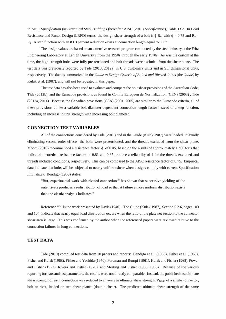
The test data was then plotted as shown in Figure 1 after being conditioned according to the AISC (2010)
specifications limit states of connection gross area and net area requirements, respectively. The specifications
limit states were modified by a factor of 0.90. Development of this criteria is found in Tide (2010, 2012a).
Conditions for which both the gross area (Ag) and net area (An) limit states are satisfied, the PTEST/PPRED data are
shown as a circle in Figure 1. The plotted data are in a non-dimensional form, eliminating the variability of bolt
diameter, material type and connection configuration. When only one of the limit state is satisfied, the data are
shown as a triangle. When neither limit state is satisfied, the data are shown as a square.
Figure 1. Test data plotted indicating limit state considerations
The data plotted in this form clearly indicate that when the connection gross and net area limit states were
satisfied all bolts in the connection were approximately equally loaded to their maximum shear capacity. As
shown in the Appendix of Tide (2010) this load condition occurs when the gross area (Ag) and net area (An)
comply with the following:
Ag ≥ 0.47 As Fu/Fyp (2)
and
An ≥ 0.56 As Fu/Fup (3)
4
Where:
Ag = connection plate gross area (in2)
An = connection plate net area (in2)
As = total effective bolt shear area (in2)
Fu = bolt ultimate tensile stress (ksi)
Fyp = plate yield stress (ksi)
Fup = plate ultimate tensile stress (ksi)
This condition is implied when Figures 5.24 and 5.25 of the Guide (Kulak (1987)) are examined for large
An/As ratios.
It has been shown by Tide (2010, 2012a, 2012b, 2014) that bolt diameter, current rivet and bolt material,
and current plate material grades do not influence the connection capacity provided the specification limit states
are satisfied. These limit states have been addressed when the plate material gross area (Ag) and net area (An)
requirements were developed as shown in Equations 2 and 3, respectively. Therefore, these subjects will not be
discussed further in this paper.
Ocel (2013) has addressed bolted and riveted connections designs in steel framed bridges. A major effort
of this work appears to address the gusset plates that connect the members together. The report is essentially
silent on the historic step function for long connections that deals with the bolt or rivet ultimate shear capacity
regardless of applicable gross and net area limits in the connections.
It should be noted that once the number of bolts are chosen for a particular connection that meet the gross
and net area limit states, adding additional bolts to the connection has limited benefit. The failure mechanism
location will change from the bolts and will subsequently occur in the connected material.
DATA CONDITIONING
A total of 119 connection tests were identified. Of these, 40 tests were with rivets associated with the
design and construction of the San Francisco-Oakland Bay Bridge and contained insufficient information to be
included in this review. Of the remaining 79 connection tests, the connector distribution was 54 A325 bolts, 18
A490 bolts, 5 rivets, and 2 Huck bolts. Shingle connection data were also removed from the database.
Furthermore, it was stipulated that connection test results would only be considered provided that the limit states
of gross area and net area were also satisfied. The statistical analysis was performed using the remaining seven
A325 and eleven A490 bolted connections. Because of the many connection variables, the test data was reduced
to a non-dimensional form to limit the significance of all the variables. As a result, the connection length remained
as the desired and predominate independent variable.
In the previous papers by Tide (2010, 2012a) all of the test results were included in the database. Test
data that was significantly below the specification limit states was used to determine the connection reliability and
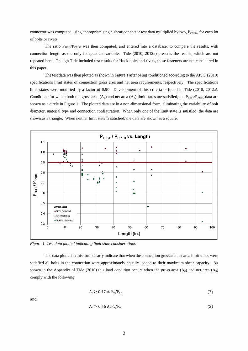
related resistance factor. Alternatively, Tide (2012b, 2014) chose the data whose test results mostly satisfied the
gross area and net area limit states. As seen in Figure 2, the data was further divided into two distinct groups.
The first group included nine test results having a connection length of 10.5 in. The second group included nine
test results having connection lengths that varied from 21.0 in to 84.0 in. The relevant test results are given in
5
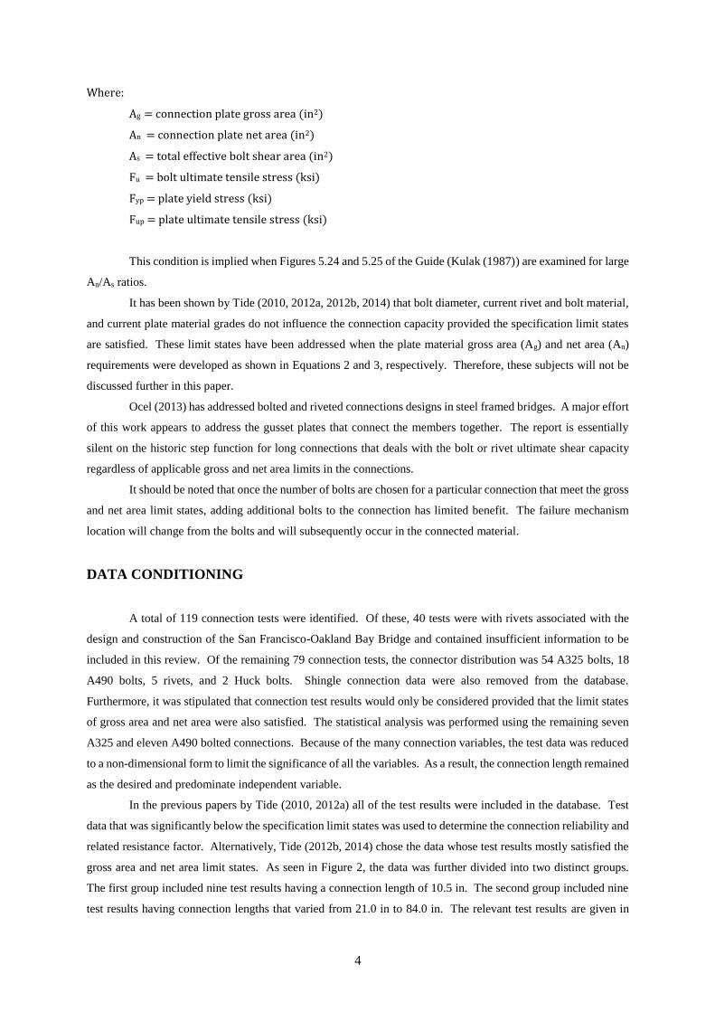
Tables 1 and 2, respectively. The two data groups were separated because it was felt that the nine test results at
10.5 in. would unacceptably influence the reliability calculations of the other nine test results having significant
variation in connection lengths.
Figure 2. Regression analysis of test data that satisfied both limit states
Table 1. Limit State Comparison for Compact Bolt Group Connections
Test
No.
Bolt
Type
Bolts
in Line
D
(in)
L
(in)
PTest
PPred
Ag
(in2)
Agl(1)
(in2) Ag/Agl
An
(in2)
Anl (2)
(in2) An/Anl
1 A325 4 1-1/8 10.5 1.001 13.0 8.3 1.52 8.07. 7.8 1.04
2 A325 4 1-1/8 10.5 1.012 13.8 8.3 1.66 8.9 7.8 1.14
3 A325 4 1-1/8 10.5 1.005 14.5 8.3 1.75 9.66 7.8 1.24
4 A325 4 1-1/8 10.5 1.010 15.4 8.3 1.86 10.5 7.8 1.35
5 A325 4 1-1/8 10.5 1.022 16.3 8.3 1.96 11.4 7.8 1.46
11 A490 4 1 10.5 1.020 13.9 9.6 1.45 9.58 9.0 1.06
12 A490 4 1 10.5 1.012 14.6 9.6 1.52 10.3 9.0 1.14
13 A490 4 1 10.5 0.994 15.2 9.6 1.58 10.9 9.0 1.21
14 A490 4 1 10.5 1.006 16.0 9.6 1.67 11.6 9.0 1.29
Mean 1.009 1.663 1.214
Standard Deviation 0.009 0.169 0.137 (1) Agl= 0.90AsFub/Fyp (2) Anl= 0.90AsFub/Fup
6
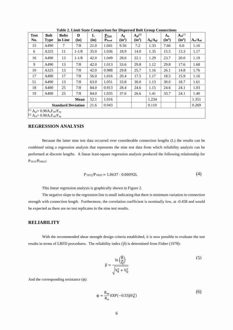
Table 2. Limit State Comparison for Dispersed Bolt Group Connections
Test
No.
Bolt
Type
Bolts
in Line
D
(in)
L
(in)
PTest
PPred
Ag
(in2)
Agl(1)
(in2) Ag/Agl
An
(in2)
Anl(2)
(in2) An/Anl
15 A490 7 7/8 21.0 1.041 9.56 7.2 1.33 7.66 6.6 1.16
6 A325 11 1-1/8 35.0 1.036 18.9 14.0 1.35 15.5 13.3 1.17
16 A490 13 1-1/8 42.0 1.049 28.6 22.1 1.29 23.7 20.0 1.19
9 A490 13 7/8 42.0 1.013 33.6 29.8 1.12 29.8 17.6 1.68
10 A325 13 7/8 42.0 0.988 29.8 25.7 1.16 26.1 14.8 1.76
17 A490 17 7/8 56.0 1.016 20.4 17.5 1.17 18.5 15.9 1.16
51 A490 13 7/8 63.0 1.051 33.8 30.0 1.13 30.0 18.7 1.61
18 A490 25 7/8 84.0 0.913 28.4 24.6 1.15 24.6 24.1 1.03
19 A490 25 7/8 84.0 1.035 37.6 26.6 1.41 33.7 24.1 1.40
Mean 52.1 1.016 1.234 1.351
Standard Deviation 21.6 0.043 0.110 0.269 (1) Agl= 0.90AsFub/Fyp (2) Anl= 0.90AsFub/Fup
REGRESSION ANALYSIS
Because the latter nine test data occurred over considerable connection lengths (L) the results can be
combined using a regression analysis that represents the nine test data from which reliability analysis can be
performed at discrete lengths. A linear least-square regression analysis produced the following relationship for
PTEST/PPRED:
PTEST/PPRED = 1.0637 - 0.00092L
This linear regression analysis is graphically shown in Figure 2.
The negative slope to the regression line is small indicating that there is minimum variation in connection
strength with connection length. Furthermore, the correlation coefficient is nominally low, at -0.458 and would
be expected as there are no test replicates in the nine test results.
RELIABILITY
With the recommended shear strength design criteria established, it is now possible to evaluate the test
results in terms of LRFD procedures. The reliability index ( ) is determined from Fisher (1978):
β =
ln (R̅Q̅
)
√VR2 + VQ
2
And the corresponding resistance (ϕ):
ϕ =Rm
Rn
EXP(−0.55β𝑉R2)
(5)
(6)
(4)
7
Where:
ϕ = bolt shear resistance
R̅ = mean resistance
Q̅ = mean load effect
VR, VQ = coefficients of variation for R̅ and Q̅ , respectively
Rm = mean test value
Rn = proposed connection length design criteria, (R2)
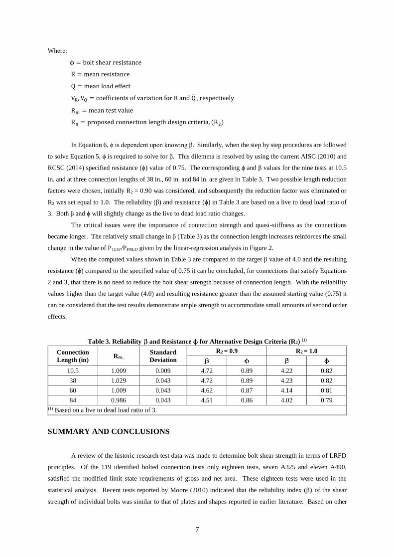
In Equation 6, ϕ is dependent upon knowing β. Similarly, when the step by step procedures are followed
to solve Equation 5, ϕ is required to solve for β. This dilemma is resolved by using the current AISC (2010) and
RCSC (2014) specified resistance (ϕ) value of 0.75. The corresponding ϕ and β values for the nine tests at 10.5
in. and at three connection lengths of 38 in., 60 in. and 84 in. are given in Table 3. Two possible length reduction
factors were chosen, initially R2 = 0.90 was considered, and subsequently the reduction factor was eliminated or
R2 was set equal to 1.0. The reliability (β) and resistance (ϕ) in Table 3 are based on a live to dead load ratio of
3. Both β and ϕ will slightly change as the live to dead load ratio changes.
The critical issues were the importance of connection strength and quasi-stiffness as the connections
became longer. The relatively small change in β (Table 3) as the connection length increases reinforces the small
change in the value of PTEST/PPRED given by the linear-regression analysis in Figure 2.
When the computed values shown in Table 3 are compared to the target β value of 4.0 and the resulting
resistance (ϕ) compared to the specified value of 0.75 it can be concluded, for connections that satisfy Equations
2 and 3, that there is no need to reduce the bolt shear strength because of connection length. With the reliability
values higher than the target value (4.0) and resulting resistance greater than the assumed starting value (0.75) it
can be considered that the test results demonstrate ample strength to accommodate small amounts of second order
effects.
Table 3. Reliability and Resistance for Alternative Design Criteria (R2) (1)
Connection
Length (in) Rm_
Standard
Deviation
R2 = 0.9 R2 = 1.0
10.5 1.009 0.009 4.72 0.89 4.22 0.82
38 1.029 0.043 4.72 0.89 4.23 0.82
60 1.009 0.043 4.62 0.87 4.14 0.81
84 0.986 0.043 4.51 0.86 4.02 0.79 (1) Based on a live to dead load ratio of 3.
SUMMARY AND CONCLUSIONS
A review of the historic research test data was made to determine bolt shear strength in terms of LRFD
principles. Of the 119 identified bolted connection tests only eighteen tests, seven A325 and eleven A490,
satisfied the modified limit state requirements of gross and net area. These eighteen tests were used in the
statistical analysis. Recent tests reported by Moore (2010) indicated that the reliability index (β) of the shear
strength of individual bolts was similar to that of plates and shapes reported in earlier literature. Based on other
8
anecdotal information there does not appear to be any justification to change the current AISC/RCSC resistance (ϕ) unless
all second order effects are considered and addressed.
The commentary to the AISC Specification (AISC 2010) indicates an implied reliability (β) of approximately 4.0
for connections. In comparison, manufactured main members typically have β of approximately 3.0, or slightly lower.
Because the bolt itself is a manufactured product, there is some leeway as to what β is acceptable. As a practical
matter it is prudent to retain a computed reliability relatively close to or greater than the stated goal of 4.0, as
shown in Table 3. This eliminates the need for detailed second order analysis for routinely used connections. To
accomplish this, the current resistance (ϕ) of 0.75 was used in the computations although the resulting computations
(Table 3) and research by Moore (2010) indicate the resistance could be increased.
An unexpected result of the study was the realization that under circumstances of sufficient or slightly increased
code required connection strength, as manifested by the net area (An), and in conjunction with connection quasi-stiffness,
as manifested by the connection gross area (Ag) in comparison to the total bolt shear area (As), there would be no need for
a connection strength reduction R2 less than 0.90 with increasing length. The R2 factor could possibly even equal 1.0. This
condition exists when the inequalities expressed in Equations 2 and 3 are satisfied. Equation 2 is not exactly a stiffness
criterion, but it indicates that the connection plates remain essentially elastic as the bolt ultimate shear strength is reached.
All of the test data represent uniaxial loaded connections with no second order effects. In reality many
connections actually result in small amounts of unintended and unaccounted for second order effects. Although not
explicitly stated, this phenomena is partially addressed by the specifications by employing a slightly reduced resistance (ϕ)
of 0.75 as compared to the value obtained from single bolt tests as reported by Moore (2010).
As a result, it is probable that the current reduction factor of 0.90 for connection lengths less than or equal to 38
in. is slightly conservative and the step function change to a reduction factor of 0.75 for connections greater than 38 in. is
excessively conservative. Removing the connection length reduction factor, R2 = 1.0, would maintain a reliability (β) equal
to or greater than 4.0 for all connection lengths. Bolted connections with obvious second order effects would have to be
properly addressed following LRFD principles.
The statistical study was based on ASTM A325 and A490 bolts; however, limited studies indicate that
similar results were obtained for rivets with no inconsistencies found. The connection plate material varied from
relatively low strength to high strength steel. This would indicate that the proposed solution is applicable for other
connectors and material, provided the specification limit states for gross area (Ag) and net area (An) are satisfied
as well as Equations 2 and 3.
ACKNOWLEDGEMENTS
The author wishes to acknowledge several colleagues who assisted him in this bolted connection study:
T.V. Galambos, who set up the reliability procedure that was used to calibrate β; D.D. Crampton, who prepared
the graphic presentations and assisted with some data interpretations.
REFERENCES
AISC (2010), Specification for Structural Steel Buildings, ANSI/AISC 360-10, American Institute of Steel
Construction, Chicago, Illinois.
9
Bendigo, R.A., R.M. Hansen, and J.L. Rumpf (1963), “Long Bolted Joints,” Journal of the Structural Division,
ASCE, Vol. 89, No. ST 6, Proc. Paper 3727, December 1963.
CEN (2003), Eurocode 3: Design of Steel Structures, European Committee for Standardization, Brussels,
Belgium, November 2003.
CSA (2001), “Limit States Design of Steel Structures,” CSA-S16-01, Canadian Standards Association, Rexdale,
Ontario, Canada.
CSA (2005), “Supplement 1 to CAN/CSA-S16-01, Limit States Design of Steel Structures. CSA S16s1-05,
Canadian Standards Association, Rexdale, Ontario, Canada.
Davis, R.E., G.B. Woodruff, and H.E. Davis (1940), “Tension Tests of Large Riveted Joints,” Transactions,
ASCE, Vol. 105, 1940
Fisher, J.W., P.O. Ramseier, and L.S. Beedle (1963), “Strength of A440 Steel Joints Fastened with A325 Bolts,”
Publications, IABSE, Vol. 23, 1963.
Fisher, J.W., and J.L. Rumpf (1965), “Analysis of Bolted Butt Joints,” Journal of the Structural Division, ASCE,
Vol. 91, No. ST5, October 1965
Fisher, J.W., and G.L. Kulak (1968), “Tests of Bolted Butt Splices,” Journal of the Structural Division, ASCE,
Vol. 94, ST11, November 1968.
Fisher, J.W., and N. Yoshida (1970), “Large Bolted and Riveted Shingle Splices,” Journal of the Structural
Division, ASCE, Vol. 96, No. ST9, Proc. Paper 7534, September 1970.
Fisher, J.W., T.V. Galambos, G.L. Kulak, and M.K. Ravindra (1978), “Load and Resistance Factor Design Criteria
for Connectors,” Journal of Structural Division, ASCE, Vol. 104, No. ST9, September 1978.
Foreman, R.T. and J.L. Rumpf (1961), “Static Tension Tests of Compact Bolted Joints,” Transactions, ASCE,
Vol. 126, 1961.
Kulak, G.L. and J.W. Fisher (1968), “A514 Steel Joints Fastened by A490 Bolts,” Journal of the Structural
Division, ASCE, Vol. 94, No. ST10, October 1968.
Kulak, G.L., J.W. Fisher, and J.H.A Struik (1987), “Guide to Design Criteria for Bolted and Riveted Joints,” 2nd
edition, John Wiley and Sons, New York, New York, 1987.
10
Moore, A.M., G.A. Rassati, J.A. Swanson (2010), “An Experimental Analysis of Strength and Ductility of High-
Strength Fasteners,” Engineering Journal, Vol. 47, No. 3, 2010, American Institute of Steel Construction, Inc.,
Chicago, Illinois.
Ocel; J.M. (2013), “Guidelines for the Load and Resistance Factor Design and Rating of Riveted and Bolted
Gusset-Plate Connections for Steel Bridges,” National Cooperative Highway Research Program (Project 12-84),
February 2013.
Power, E.H., and J.W. Fisher (1972), “Behavior and Design of Shingle Joints,” Journal of the Structural Division,
ASCE, Vo. 98, No. ST9, September 1972.
RCSC (2014) Specifications for Structural Joints Using High Strength Bolts, Research Council on Structural
Connections, Chicago, Illinois, August 1, 2014
Rivera, U., and J.W. Fisher (1970), “Load Partition and Ultimate Strength of Shingle Joints,” Fritz Laboratory
Report 340.6, Lehigh University, 1970.
Sterling, G.H., and J.W. Fisher (1965), “A440 Steel Joints Connected by A490 Bolts,” Journal of the Structural
Division, ASCE, Vol. 92, No. ST3, Proc. Paper 4845, June 1966.
Sterling G.H., and J.W. Fisher (1966), “Tests of Long A440 Steel Bolted Butt Joints,” Fritz Engineering
Laboratory Report No. 288.26, Lehigh University, 1965.
Tide, R.H.R (2010), “Bolt Shear Design Considerations,” Engineering Journal, Vol. 47, No. 1, 2010, American
Institute of Steel Construction, Inc., Chicago, Illinois
Tide, R.H.R., (2012a), “Shear Strength of High Strength Bolts©,” Wiss, Janney, Elstner Associates, Inc.,
Northbrook, Illinois
Tide, R.H.R., (2012b), “Re-evaluation of Shear Strength of High Strength Bolts in AS4100,” ACMSM 22
Conference, University of Technology, Sydney, NSW, Australia
Tide, R.H.R. (2014), “High Strength Bolt Shear Capacity in Long Connections,” 7th European Conference on
Steel and Composite Structures, College of Engineering, University of Napoli Federico II, Naples, Italy
------------------------------------For Committee Use Below-----------------------------------------------
Date Received: 7/25/14 Exec Com Meeting: 8/20/14 Forwarded: Yes X /No □
Committee Assignment: Executive -A. □ Editorial -B. □ Nominating -C. □
Specifications -A.1 X Research -A.2 □ Membership & Funding -A.3 □ Education -A.4 □ Committee Chair: Carter Task Group #: ___________ T.G. Chair: ________________ Date Sent to Main Committee: _______________Final Disposition: ______________________
Revision 4/01/10
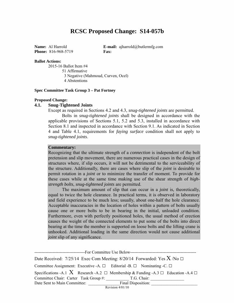
RCSC Proposed Change: S14-057b Name: Al Harrold E-mail: [email protected] Phone: 816-968-5719 Fax: Ballot Actions:
2015-16 Ballot Item #4 51 Affirmative 3 Negative (Mahmoud, Curven, Ocel) 4 Abstentions
Spec Committee Task Group 3 – Pat Fortney Proposed Change: 4.1. Snug-Tightened Joints
Except as required in Sections 4.2 and 4.3, snug-tightened joints are permitted. Bolts in snug-tightened joints shall be designed in accordance with the applicable provisions of Sections 5.1, 5.2 and 5.3, installed in accordance with Section 8.1 and inspected in accordance with Section 9.1. As indicated in Section 4 and Table 4.1, requirements for faying surface condition shall not apply to snug-tightened joints.
Commentary: Recognizing that the ultimate strength of a connection is independent of the bolt pretension and slip movement, there are numerous practical cases in the design of structures where, if slip occurs, it will not be detrimental to the serviceability of the structure. Additionally, there are cases where slip of the joint is desirable to permit rotation in a joint or to minimize the transfer of moment. To provide for these cases while at the same time making use of the shear strength of high-strength bolts, snug-tightened joints are permitted.
The maximum amount of slip that can occur in a joint is, theoretically, equal to twice the hole clearance. In practical terms, it is observed in laboratory and field experience to be much less; usually, about one-half the hole clearance. Acceptable inaccuracies in the location of holes within a pattern of bolts usually cause one or more bolts to be in bearing in the initial, unloaded condition. Furthermore, even with perfectly positioned holes, the usual method of erection causes the weight of the connected elements to put some of the bolts into direct bearing at the time the member is supported on loose bolts and the lifting crane is unhooked. Additional loading in the same direction would not cause additional joint slip of any significance.
RCSC Proposed Change S14-057
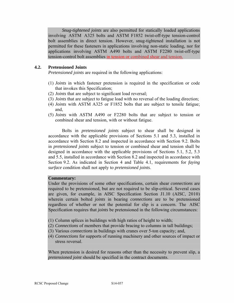
Snug-tightened joints are also permitted for statically loaded applications involving ASTM A325 bolts and ASTM F1852 twist-off-type tension-control bolt assemblies in direct tension. However, snug-tightened installation is not permitted for these fasteners in applications involving non-static loading, nor for applications involving ASTM A490 bolts and ASTM F2280 twist-off-type tension-control bolt assemblies in tension or combined shear and tension.
4.2. Pretensioned Joints
Pretensioned joints are required in the following applications: (1) Joints in which fastener pretension is required in the specification or code
that invokes this Specification; (2) Joints that are subject to significant load reversal; (3) Joints that are subject to fatigue load with no reversal of the loading direction; (4) Joints with ASTM A325 or F1852 bolts that are subject to tensile fatigue;
and, (5) Joints with ASTM A490 or F2280 bolts that are subject to tension or
combined shear and tension, with or without fatigue.
Bolts in pretensioned joints subject to shear shall be designed in accordance with the applicable provisions of Sections 5.1 and 5.3, installed in accordance with Section 8.2 and inspected in accordance with Section 9.2. Bolts in pretensioned joints subject to tension or combined shear and tension shall be designed in accordance with the applicable provisions of Sections 5.1, 5.2, 5.3 and 5.5, installed in accordance with Section 8.2 and inspected in accordance with Section 9.2. As indicated in Section 4 and Table 4.1, requirements for faying surface condition shall not apply to pretensioned joints.
Commentary: Under the provisions of some other specifications, certain shear connections are required to be pretensioned, but are not required to be slip-critical. Several cases are given, for example, in AISC Specification Section J1.10 (AISC, 2010) wherein certain bolted joints in bearing connections are to be pretensioned regardless of whether or not the potential for slip is a concern. The AISC Specification requires that joints be pretensioned in the following circumstances: (1) Column splices in buildings with high ratios of height to width; (2) Connections of members that provide bracing to columns in tall buildings; (3) Various connections in buildings with cranes over 5-ton capacity; and, (4) Connections for supports of running machinery and other sources of impact or
stress reversal. When pretension is desired for reasons other than the necessity to prevent slip, a pretensioned joint should be specified in the contract documents.
RCSC Proposed Change S14-057
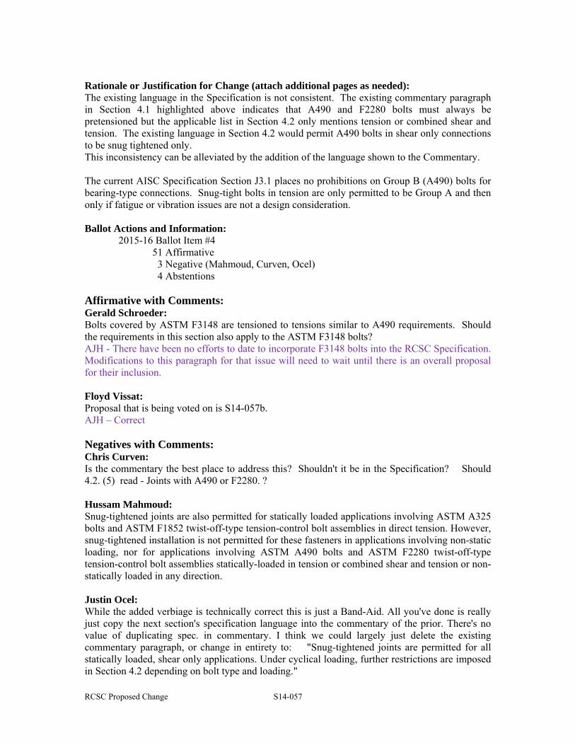
Rationale or Justification for Change (attach additional pages as needed): The existing language in the Specification is not consistent. The existing commentary paragraph in Section 4.1 highlighted above indicates that A490 and F2280 bolts must always be pretensioned but the applicable list in Section 4.2 only mentions tension or combined shear and tension. The existing language in Section 4.2 would permit A490 bolts in shear only connections to be snug tightened only. This inconsistency can be alleviated by the addition of the language shown to the Commentary. The current AISC Specification Section J3.1 places no prohibitions on Group B (A490) bolts for bearing-type connections. Snug-tight bolts in tension are only permitted to be Group A and then only if fatigue or vibration issues are not a design consideration. Ballot Actions and Information:
2015-16 Ballot Item #4 51 Affirmative 3 Negative (Mahmoud, Curven, Ocel) 4 Abstentions
Affirmative with Comments: Gerald Schroeder: Bolts covered by ASTM F3148 are tensioned to tensions similar to A490 requirements. Should the requirements in this section also apply to the ASTM F3148 bolts? AJH - There have been no efforts to date to incorporate F3148 bolts into the RCSC Specification. Modifications to this paragraph for that issue will need to wait until there is an overall proposal for their inclusion. Floyd Vissat: Proposal that is being voted on is S14-057b. AJH – Correct Negatives with Comments: Chris Curven: Is the commentary the best place to address this? Shouldn't it be in the Specification? Should 4.2. (5) read - Joints with A490 or F2280. ? Hussam Mahmoud: Snug-tightened joints are also permitted for statically loaded applications involving ASTM A325 bolts and ASTM F1852 twist-off-type tension-control bolt assemblies in direct tension. However, snug-tightened installation is not permitted for these fasteners in applications involving non-static loading, nor for applications involving ASTM A490 bolts and ASTM F2280 twist-off-type tension-control bolt assemblies statically-loaded in tension or combined shear and tension or non-statically loaded in any direction. Justin Ocel: While the added verbiage is technically correct this is just a Band-Aid. All you've done is really just copy the next section's specification language into the commentary of the prior. There's no value of duplicating spec. in commentary. I think we could largely just delete the existing commentary paragraph, or change in entirety to: "Snug-tightened joints are permitted for all statically loaded, shear only applications. Under cyclical loading, further restrictions are imposed in Section 4.2 depending on bolt type and loading."

RCSC Proposed Change S14-057
Abstain with Comments: None