rd-wired remote manual
TRANSCRIPT

TurboCharger™ T80 Remote Display
Installation and Operation Manual
23 Francis J. Clarke Circle, Bethel, CT 06801 USA (203) 790-6400
www.ApolloSolar.com

TurboCharger™ T80 Remote Display Installation and Operation Manual Page 1
TABLE OF CONTENTS
Revision History ...........................................................................................2
Overview ......................................................................................................3
Features .......................................................................................................3
Accessories..................................................................................................4
Installation Instructions.................................................................................4
SD Memory Card .........................................................................................6
Insertion and removal of the SD Memory Card..................................7
Initializing the T80 ........................................................................................7
Remote Display Setup..................................................................................9
Operating the T80 Remote Readout ............................................................9
Welcome Screen ...............................................................................9
Status Screens ..................................................................................9
Setup Screens...................................................................................10
Main Energy Monitor Screen .............................................................14
Data Screens.....................................................................................14
Front Panel LED Status Indicator.................................................................16
Bootloader Operation ...................................................................................16
Specifications ...............................................................................................19
Warranty Information....................................................................................20

TurboCharger™ T80 Remote Display Installation and Operation Manual Page 2
Revision History
Manual Revision Applies to Firmware Revision Date BY
Preliminary 5/10/07 KMV
1.0 1.0 (Remote Display) 5.0 (T80) 7/18/07 KMV
1.1 1.01 (Remote Display) 5.05 (T80) 8/10/07 KMV
1.2 1.02 (Remote Display) 6.00 (T80) 9/12/07 KMV
1.3 1.05 (Remote Display) 6.10 (T80) 4/22/08 KMV
1.4 2.00 (Remote Display) 8.00(T80) 6/1/10 HF
1.5 2.00 (Remote Display) 8.00(T80) 5/5/11 HF
TurboCharger™ T80 Remote Display Installation and Operation Manual Page 3
OVERVIEW
The TurboCharger™ T80 Remote Display is essentially an extension of the T80 front panel display. It is designed to be used in a remote location to offer the user the convenience of monitoring the T80’s performance without going to its installation site, such as a garage, basement or outdoor shed.
Battery Energy Monitor Display is Essential The T80 TurboChargerTM includes a built-in energy monitor based on TriMetric™ technology which tracks power production and consumption then calculates the energy remaining in the battery. State of Charge (SOC) is displayed in Percent Full, Amp-hours and bar graph format. This “gas gauge” is essential in battery based systems. The T80 goes further by recording 90 days of historical data on energy production, usage, and number of days since fully charged. The Remote Display shows all the information at a glance at a convenient location, and with the optional SD Memory Card, this can be extended to over a year. It also offers a convenient way to monitor all of the T80s in a “stacked” system.
Monitor the PV and Battery System from anywhere Battery system management in a convenient portable package. See what the PV array, Charge Controller, Batteries and Load are doing any time. Check the results for each day for the last year.
SD Memory Card for enhanced Energy Monitor The SD Memory Card expands the Energy Monitor function to over a year, and stores data for all T80s in the system. Through the use of this technology, the serious user can use additional cards to archive data for years to come. The SD Memory Card also stores vital system information which is used by Apollo Solar Monitoring Software. The SD Memory card also allows the user to upgrade the T80 operating firmware through the Bootloader function.
� IMPORTANT
The Remote Display is only a display; it does not effect the T80 operation. All T80 setup
functions must be performed at the T80 front panel display.
FEATURES
• Desktop enclosure can be wall mounted
• Transflective LCD with backlight
• Wiring distance up to 1000 feet.
• SD Memory Card for extended data logging
TurboCharger™ T80 Remote Display Installation and Operation Manual Page 4
ACCESSORIES
Included with the Remote Display are:
• ASNET - Network Option Card
• SD Memory Card
• 7 ft CAT5 cable – Provided for Setup and Test. For longer distances, Apollo
Solar strongly recommends that the cable be installed by a qualified network
installer.
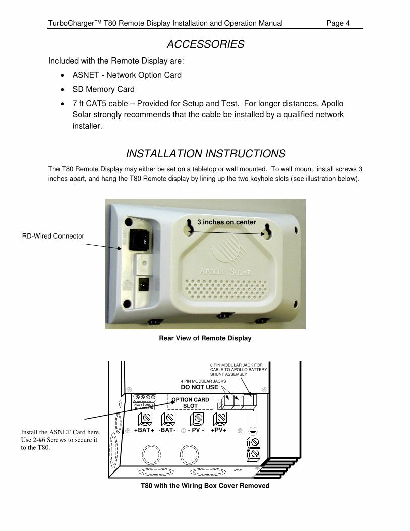
INSTALLATION INSTRUCTIONS
The T80 Remote Display may either be set on a tabletop or wall mounted. To wall mount, install screws 3
inches apart, and hang the T80 Remote display by lining up the two keyhole slots (see illustration below).
Rear View of Remote Display
T80 with the Wiring Box Cover Removed
3 inches on center
RD-Wired Connector
+ BAT + -BAT - + PV + - PV -
6 PIN MODULAR JACK FOR CABLE TO APOLLO BATTERY SHUNT ASSEMBLY
OPTION CARD SLOT AUX 1 AUX 2
N . O . RELAYS
4 PIN MODULAR JACKS
DO NOT USE
Install the ASNET Card here.
Use 2-#6 Screws to secure it
to the T80.

TurboCharger™ T80 Remote Display Installation and Operation Manual Page 5
NETWORK OPTION CARD
The RD-WIRED remote display comes with an ASNET network option card as the means of connecting it to the T80. Each ASNET card contains 2 RJ-45 modular jacks for common 8 wire CAT5 cable.
� WARNING
The ASNET is NOT an Ethernet compatible system and RJ-45 connectors must NOT be
connected to a computer or any Ethernet device.
Up to 15 additional T80s may be added in parallel by plugging into the RJ-45 Jack on the existing Network Option Card. The ASNET option includes one Network Option Card and one CAT5 cable. One Network Option Card is required for each T80 in the system. See the T80 User Manual for detailed setup instructions.

TurboCharger™ T80 Remote Display Installation and Operation Manual Page 6
� IMPORTANT
The CAT 5 cable must be wired in the standard configuration (i.e. straight through, “one to
one”), not “crossover”. When wiring the cable, it must be wired as shown below:
SD MEMORY CARD
The SD Memory Card enables the Remote Display to store important system information for
each of the T80 charge controllers. It is organized in two files. The first file stores vital data
such as voltage and current of both the PV array and Battery bank with a date and time stamp.
It also stores other system data which is utilized by Apollo Solar Monitoring Software. The
second file is the Data Harvest file which stores the energy produced by each T80 for over a
year.
� IMPORTANT
The SD card must be installed to display the cumulative data harvest screens. Without it,
only the daily energy harvest data can be viewed.
The SD card must be formatted for FAT16 files structures. To assure compatibility, it is recommended that the cards be purchased from Apollo Solar.
The SD Memory Card extends the data collection time beyond the T80’s 90 day range to over a
year. If the SD Memory Card is not installed, only the daily (Today) energy harvest data will be
displayed. For cumulative data, only the data saved by the T80(s) is available.
An icon appears at the bottom right of the display which indicates the memory card is being
accessed. It appears for several seconds (depending on the number of networked T80s) every
10 seconds.
� IMPORTANT
When this icon appears, the keypad functions are locked out, and screens cannot be
changed. This is normal operation.
1 1
2
3
4
5
6
7
8
2
3
4
5
6
7
8
White/Green
Green
White/Orange
Blue
White/Blue
Orange
White/Brown
Brown

TurboCharger™ T80 Remote Display Installation and Operation Manual Page 7
INSERTION AND REMOVAL OF THE SD CARD
To insert the SD card: Insert the card into the slot on the left side of the Remote Display, with
the label facing toward you (see below). Push in until it clicks.
To remove the SD card: If the memory access icon is not visible, press the edge of the card
inward slightly, and release. The card will pop out. Grasp the card and pull it out. Do not
attempt remove the SD card if the memory access icon appears to assure that no data is
lost.
Data files on the SD card may be transferred to a PC using a commercially available SD
Card reader (SD card to USB).
INITIALIZING THE T80
1. Turn ON the battery breaker for the Master Unit.
2. The unit will come up with the Splash screen indication that a network card is detected and shown below. This screen remains for approximately 7 seconds.
A P O L L O S O L A R
T U R B O C H A R G E R T 8 0
R E V : # . # # P : # # C : # #
S / N : # # # # # # A S N E T V 2
3. The Apollo Net Address Screen will then appear. If the Remote Display is being installed on a single T80, use the + and – buttons to set the Address to Standalone and press DONE. If the Remote Display is being installed along with networked (stacked) T80s, proceed to step 8.
A P O L L O N E T S E T U P
A D D R E S S = S T A N D A L O N E
- + D O N E
4. Turn off the output (battery) breaker.

TurboCharger™ T80 Remote Display Installation and Operation Manual Page 8
5. Turn ON the output (battery) breakers.
6. Follow the initialization screens, and reset the clock.
7. The following screen will appear Turn On all the PV breakers and you are charging batteries.
T U R N O N P V I N P U T
B R E A K E R N O W
N E X T 8. If there are networked (stacked) T80s in the system, a Master must be set up first (the
master is the unit that the Apollo Shunt is connected to). The Apollo Net Address Screen will then appear. Use the + and – buttons to set the Address to Master and press DONE.
A P O L L O N E T S E T U P
A D D R E S S = M A S T E R
- + D O N E
9. Continue to set up the Master Unit as detailed in the T80 User Manual.
10. Turn ON the output (battery) breaker for the first Slave Unit. It doesn’t matter which one.
11. The Unit will come up with the Splash screen indication that a network card is detected (as in Step 5).
12. The Apollo Net Setup Screen will then appear (as in Step 6.) Use the + and – buttons to set the Address to Slave #01 and press DONE.
13. The Battery Setup 2 Screen will then appear and then you must enter the correct
Maximum Charge Current for this unit. It will usually be based on the battery Capacity
and thus the same as on the Master Unit unless smaller gauge wiring was used on this
Unit.
B A T T E R Y S E T U P 2
M A X C H A R G E A M P S = # # A
B A C K - + N E X T
14. Repeat steps 8-11 to for each additional slave unit selecting a different Slave Address for each.
15. After setting up all the slave units turn off the output (battery) breakers for all the units.
16. Turn ON the output (battery) breakers for all the units one at a time in any order.
17. On the Master Unit follow the T80 manual section RESTARTING THE T80.
18. On each Slave Unit the Following Screen will appear. Press The KEEP button unless the Current is incorrect or the system parameters have changed.

TurboCharger™ T80 Remote Display Installation and Operation Manual Page 9
B A T T E R Y S E T U P 2
M A X C H A R G E A M P S = # # A
C H A N G E K E E P
19. The following screen will appear Turn On all the PV breakers and you are charging batteries.
T U R N O N P V I N P U T
B R E A K E R N O W
N E X T
REMOTE DISPLAY SETUP
The Remote Display must be set up with the number of T80s that are on the network (in a single
T80 system, it must be set to 1). Since multiple Remote Displays are supported, one unit must
be set as the Master. The master keeps track of the clock, and controls traffic to assure that
there are no data collisions on the network. If there is only one Remote Display in the system, it
must also be set as the Master. Refer to the Network Setup Screen on page 16 of this manual.
OPERATING THE REMOTE DISPLAY
To turn on the Wireless Remote Display, press any of the buttons located below the screen.
The Wired Remote Display turns on as soon as the CAT5 cable is connected and the battery is
connected to the T80. The welcome screen will display.
Welcome Screen
The Welcome screen provides information on the numeric software revision (X.XX above). If the SD
memory card is installed, “INITIALIZING SD CARD” will display on the bottom line. After seven seconds
the main status screen will be displayed.
STATUS SCREENS
1M Main Status Screen
Once the initial setup is complete the T80 operates automatically and displays the Main Status Screen.
This screen provides vital PV system information at a glance and provides a portal to the data reporting
and custom settings features of the T80.
Display of a single T80 shown at left.
A P O L L O S O L A R
R e m o t e D i s p l a y
R E V # . # #
I N = # # # . # V # # . # A
B A T T = # # . # V # # # # . # A
���� E F # # # # . # A
M E N U S O C D A T A H H : M M
TurboCharger™ T80 Remote Display Installation and Operation Manual Page 10
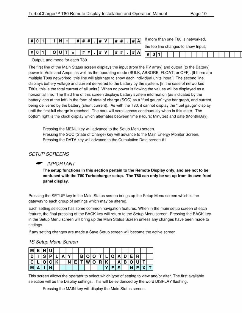
If more than one T80 is networked,
the top line changes to show Input,
# 0 1 O
Output, and mode for each T80.
The first line of the Main Status screen displays the input (from the PV array) and output (to the Battery)
power in Volts and Amps, as well as the operating mode (BULK, ABSORB, FLOAT, or OFF). [If there are
multiple T80s networked, this line will alternate to show each individual units input.] The second line
displays battery voltage and current delivered to the battery by the system. [In the case of networked
T80s, this is the total current of all units.] When no power is flowing the values will be displayed as a
horizontal line. The third line of this screen displays battery system information (as indicated by the
battery icon at the left) in the form of state of charge (SOC) as a “fuel gauge” type bar graph, and current
being delivered by the battery (shunt current). As with the T80, it cannot display the “fuel gauge” display
until the first full charge is reached. The bars will scroll across continuously when in this state. The
bottom right is the clock display which alternates between time (Hours: Minutes) and date (Month/Day).
Pressing the MENU key will advance to the Setup Menu screen.
Pressing the SOC (State of Charge) key will advance to the Main Energy Monitor Screen.
Pressing the DATA key will advance to the Cumulative Data screen #1
SETUP SCREENS
� IMPORTANT
The setup functions in this section pertain to the Remote Display only, and are not to be
confused with the T80 Turbocharger setup. The T80 can only be set up from its own front
panel display.
Pressing the SETUP key in the Main Status screen brings up the Setup Menu screen which is the
gateway to each group of settings which may be altered.
Each setting selection has some common navigation features. When in the main setup screen of each
feature, the final pressing of the BACK key will return to the Setup Menu screen. Pressing the BACK key
in the Setup Menu screen will bring up the Main Status Screen unless any changes have been made to
settings.
If any setting changes are made a Save Setup screen will become the active screen.
1S Setup Menu Screen
M E N U
D I S P L A Y B O O T L O A D E R
C L O C K N E T W O R K A B O U T
M A I N Y E S N E X T
This screen allows the operator to select which type of setting to view and/or alter. The first available
selection will be the Display settings. This will be evidenced by the word DISPLAY flashing.
Pressing the MAIN key will display the Main Status screen.
# 0 1 I N = # # # . # V # # . # A
# 0 1 O U T = # # . # V # # . # A

TurboCharger™ T80 Remote Display Installation and Operation Manual Page 11
Pressing the YES key will advance to the main setup screen of the active selection.
Pressing the NEXT key will move the active selection forwards one selection. When all selections
are tabbed through and the ABOUT selection is reached, pressing the NEXT key will
cycle around to DISPLAY.
2S Display Menu Screen
D I S P L A Y M E N U
B A C K L I G H T
S L E E P
B A C K Y E S N E X T
This screen allows the operator to select which type of display setting to view and/or alter. The two
available selections are Backlight and Sleep.
Pressing the BACK key will back up to the previous selection, or the Main Status screen if on
BACKLIGHT.
Pressing the YES key will advance to the main setup screen of the active selection.
Pressing the NEXT key will toggle between the two selections.
3S Backlight Setup Screen
T U R N O F F B A C K L I G H T :
A F T E R # # M I N U T E S
B A C K - +
This screen allows the operator to set the operation of the LCD backlight. Since the backlight consumes
a fair amount of quiescent current, it is recommended that the on time be as short as possible.
Pressing the BACK key will return to the Display Menu screen.
Pressing the + and – keys sets the backlight to turn off from NEVER (always on) or 1 to 10
minutes in 1 minute increments.
Note: When the backlight turns off, pressing any key will turn it on without affecting the current display
screen.
4S Sleep Setup Screen
S L E E P U N I T A F T E R :
# # M I N U T E S
B A C K - +
To further conserve power, the Remote Display can be set to shutdown the LCD when there is no need to
monitor system functions. The Remote Display’s microprocessor will continue to log data and save to the
SD memory.
Pressing the BACK key will return to the Display Menu screen.
Pressing the + and – keys sets the Remote Display to go to sleep from NEVER (always on) or 1
to 10 minutes in 1 minute increments.
Note: The sleep timer starts after the backlight turns off (e.g. If the backlight is set for 2 minutes and sleep
is set for 3 minutes, the Remote Display will enter sleep mode 5 minutes after the last key press). When
sleep mode is entered, pressing any key will turn it on without affecting the current display setup.

TurboCharger™ T80 Remote Display Installation and Operation Manual Page 12
5S Bootloader Initiation Screen
For information on operating the Bootloader, refer to the section “Bootloader
Operation”.
6S Clock Setup Screen
S E T C L O C K M O D E = # #
T I M E = H H : M M
D A T E = M M / D D / Y Y
B A C K - + N E X T
This screen is allows the user to enter the correct time and date as well as select the time format. The
installer may select either 12 hour (AM/PM) or 24 hour clock display format. Once this selection is made
the time will display 12 noon in the selected mode. Enter the correct time using the + and - keys to move
the hour and minutes values up and down. Enter the correct date in the same manner. Once set, the
Remote Display will synchronize the time of all T80s in the system. The Remote Display’s real time clock
will retain the time even if power is interrupted on the T80s.
Pressing the BACK key back up to the previous selection, or the Setup Menu screen if on the first
selection.
Pressing the NEXT key will advance to the next field. Once the last field is reached, the key
changes to DONE to save the settings.
� IMPORTANT
The time and date must be set properly as it can affect the accuracy of the Energy Harvest
function.
7S Network Setup Menu Screen
N E T W O R K M E N U
S E T U P M O D E S T A T U S
M A I N Y E S N E X T
This screen sets up the Remote Display for use in Networked (stacked) systems. The choices are:
Setup, Mode, and Status.
Select Setup to input the number of T80s on the Network.
Select Mode to displays/change the network type.
Selecting Status displays all of the T80s in the network, and indicates whether they are operating
properly.
Pressing the MAIN key back up to the Setup Menu screen.
Pressing the YES key will advance to the main setup screen of the active selection.
Pressing the NEXT key will toggle between the two selections.
Note: The Master T80 is always address 01.
8S Network Setup Screen
N E T W O R K S E T U P
T 8 0 S O N N E T W O R K : # #
M A S T E R D I S P L A Y : Y E S
B A C K - + N E X T

TurboCharger™ T80 Remote Display Installation and Operation Manual Page 13
This screen is used to input the number of T80s in the network, and select whether the Remote Display is
the Master (in systems with multiple Remote Displays).
Pressing the NEXT and BACK keys moves between the two fields.
When setting the number of T80s in the network, pressing the + and – keys increments and
decrements the number.
In a multi-remote system, one Remote Display must be set as the Master (to avoid data
collisions). If it is the only Remote Display, set to Master as well.
Pressing the DONE key (changed from NEXT) will save and return to the Network Menu screen.
9S Network Mode Screen
N E T W O R K M O D E
T Y P E : W I R E D
B A C K
The “TYPE” is set to Wired @ the factory and should not be changed.
10S Network Status Screen
0 1 X 0 2 X 0 3 X 0 4 X
0 5 X 0 6 X 0 7 X 0 8 X
0 9 X 1 0 X 1 1 X 1 2 X
1 3 X 1 4 X 1 5 X 1 6 X
This screen shows the status of all of the T80s in the Network. Only the number of T80s selected in the
Setup screen are displayed. The character after each unit number (depicted as an “X” above) is a check
mark if a unit is reporting, and an “E” (error) if it is not. Pressing any key returns to the Network Setup
Menu screen.
In addition, if a T80 is not reporting, the Main Screen will show “UNIT OFFLINE” for that T80:
# 0 2 U N I T O F F L I N E
B A T T = # # . # V # # # # . # A
M E N U D A T A H H : M M
TurboCharger™ T80 Remote Display Installation and Operation Manual Page 14
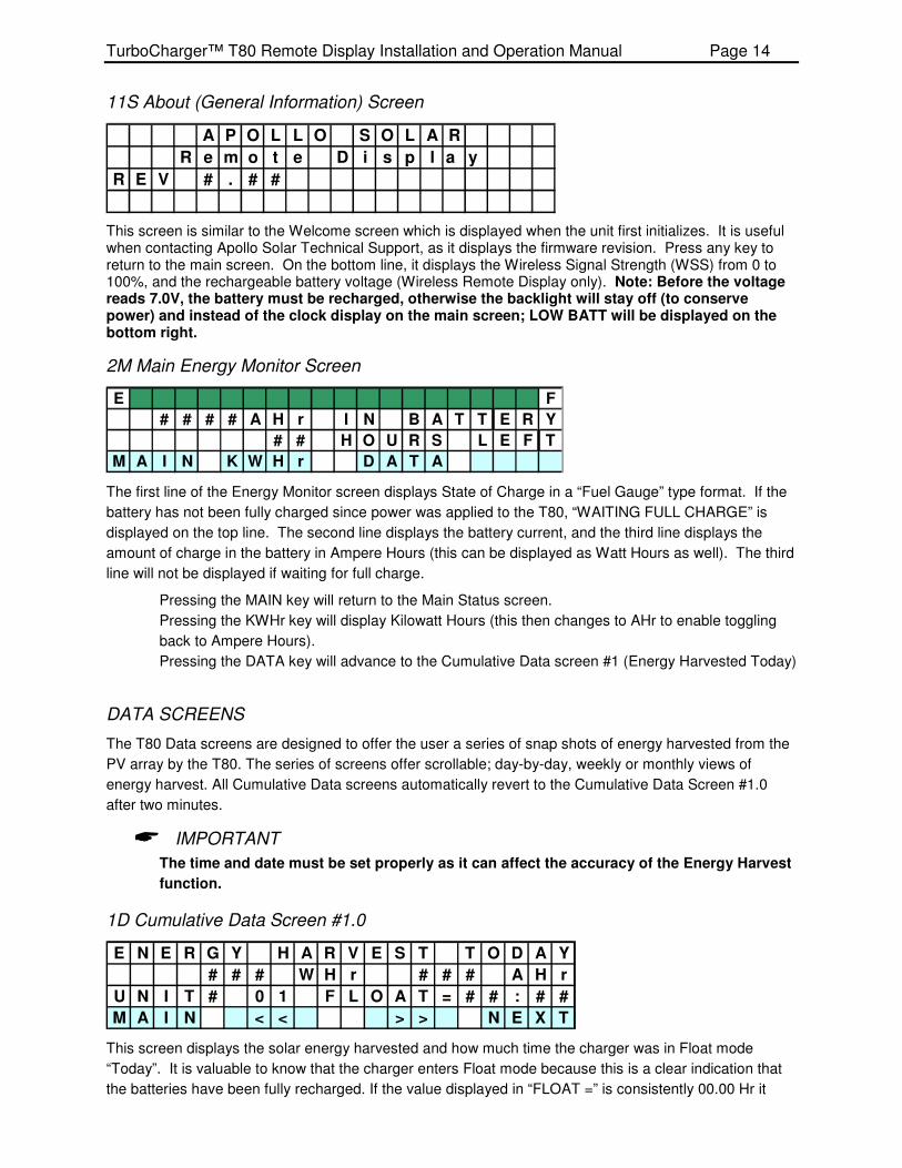
11S About (General Information) Screen
A P O L L O S O L A R
R e m o t e D i s p l a y
R E V # . # #
This screen is similar to the Welcome screen which is displayed when the unit first initializes. It is useful when contacting Apollo Solar Technical Support, as it displays the firmware revision. Press any key to return to the main screen. On the bottom line, it displays the Wireless Signal Strength (WSS) from 0 to 100%, and the rechargeable battery voltage (Wireless Remote Display only). Note: Before the voltage reads 7.0V, the battery must be recharged, otherwise the backlight will stay off (to conserve power) and instead of the clock display on the main screen; LOW BATT will be displayed on the bottom right.
2M Main Energy Monitor Screen
E F
# # # # A H r I N B A T T E R Y
# # H O U R S L E F T
M A I N K W H r D A T A
The first line of the Energy Monitor screen displays State of Charge in a “Fuel Gauge” type format. If the
battery has not been fully charged since power was applied to the T80, “WAITING FULL CHARGE” is
displayed on the top line. The second line displays the battery current, and the third line displays the
amount of charge in the battery in Ampere Hours (this can be displayed as Watt Hours as well). The third
line will not be displayed if waiting for full charge.
Pressing the MAIN key will return to the Main Status screen.
Pressing the KWHr key will display Kilowatt Hours (this then changes to AHr to enable toggling
back to Ampere Hours).
Pressing the DATA key will advance to the Cumulative Data screen #1 (Energy Harvested Today)
DATA SCREENS
The T80 Data screens are designed to offer the user a series of snap shots of energy harvested from the
PV array by the T80. The series of screens offer scrollable; day-by-day, weekly or monthly views of
energy harvest. All Cumulative Data screens automatically revert to the Cumulative Data Screen #1.0
after two minutes.
� IMPORTANT
The time and date must be set properly as it can affect the accuracy of the Energy Harvest
function.
1D Cumulative Data Screen #1.0
E N E R G Y H A R V E S T T O D A Y
# # # W H r # # # A H r
U N I T # 0 1 F L O A T = # # : # #
M A I N < < > > N E X T
This screen displays the solar energy harvested and how much time the charger was in Float mode
“Today”. It is valuable to know that the charger enters Float mode because this is a clear indication that
the batteries have been fully recharged. If the value displayed in “FLOAT =” is consistently 00.00 Hr it
TurboCharger™ T80 Remote Display Installation and Operation Manual Page 15
means that the PV array is not sufficiently sized to keep up with the load. Use a generator for additional
battery charging, reduce loads, or expand the PV array to ensure that batteries are fully recharged. For
maximum service life batteries should be fully recharged at least once every five to ten days.
Pressing the MAIN key will return to the Main Status screen.
Pressing the << or >> key will select which unit in a networked system is displayed – This is
indicated at the left of the third line of the display:
UNIT# 01 - 16: The T80s in the system
TOTAL: The total energy for the entire system.
Pressing the NEXT key will advance to the Cumulative Data screen #2 (DAY LOG)
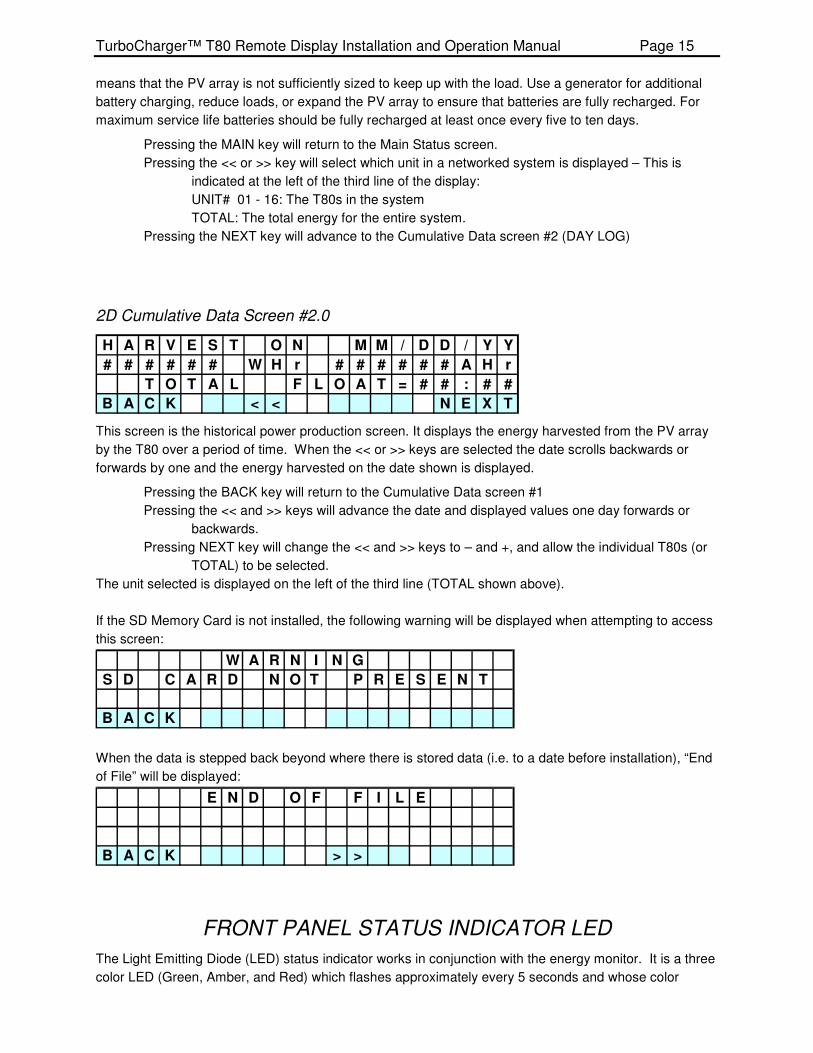
2D Cumulative Data Screen #2.0
H A R V E S T O N M M / D D / Y Y
# # # # # # W H r # # # # # # A H r
T O T A L F L O A T = # # : # #
B A C K < < N E X T
This screen is the historical power production screen. It displays the energy harvested from the PV array
by the T80 over a period of time. When the << or >> keys are selected the date scrolls backwards or
forwards by one and the energy harvested on the date shown is displayed.
Pressing the BACK key will return to the Cumulative Data screen #1
Pressing the << and >> keys will advance the date and displayed values one day forwards or
backwards.
Pressing NEXT key will change the << and >> keys to – and +, and allow the individual T80s (or
TOTAL) to be selected.
The unit selected is displayed on the left of the third line (TOTAL shown above).
If the SD Memory Card is not installed, the following warning will be displayed when attempting to access
this screen:
W A R N I N G
S D C A R D N O T P R E S E N T
B A C K
When the data is stepped back beyond where there is stored data (i.e. to a date before installation), “End
of File” will be displayed:
E N D O F F I L E
B A C K > >
FRONT PANEL STATUS INDICATOR LED
The Light Emitting Diode (LED) status indicator works in conjunction with the energy monitor. It is a three
color LED (Green, Amber, and Red) which flashes approximately every 5 seconds and whose color

TurboCharger™ T80 Remote Display Installation and Operation Manual Page 16
indicates the following:
• Green: The system battery state of charge is between 100% and 60%.
• Amber: The system battery state of charge is between 60% and 40%.
• Red: The system battery state of charge is below 40%.
� IMPORTANT
The function of the front panel LED is different than that of the T80 Turbocharger. Please
refer to the T80 manual for a description of its function.
BOOTLOADER OPERATION
The T80 Remote Display may be used to update the operating firmware of the T80 TurboCharger
TM. It will read a file from an SD memory card and reprogram the T80 with
the new file.
UPDATING THE T80 FIRMWARE
Note: Version 5.00 requires a slightly different procedure. Please call Apollo Solar
Technical Support for further instructions.
� WARNING
The following steps must be followed carefully in order for the Apollo Bootloader to
function properly. It is advised to read through the entire instructions before proceeding.
o Power down the T80 (turn off the PV breaker, then turn off the battery breaker).
o Remove the wiring box cover.
o Connect the CAT 5 cable between the Network Option Card and the T80 Remote Display
(if not already connected).
o Remove any other CAT 5 connections to the ASNET Card.
o Apply power to the T80 (turn on the battery breaker).
OPERATING THE BOOTLOADER
When power is applied to the T80, the welcome screens will be displayed on the Remote
Display.

TurboCharger™ T80 Remote Display Installation and Operation Manual Page 17
Remote Display Operations:
Welcome Screen:
After several seconds the Main Energy Screen will be displayed:
# 0 1 I N = # # # . # V # # . # A
B A T T = 0 # # . # V # # # # . # A
# # # # . # A
M E N U S O C D A T A H H : M M
Press the menu key, and the Menu Setup screen will be displayed:
M E N U
D I S P L A Y B O O T L O A D E R
C L O C K N E T W O R K A B O U T
M A I N Y E S N E X T
Press the NEXT key until “BOOTLOADER” is flashing, then press the YES key. The following
screen will be displayed:
A P O L L O B O O T L O A D E R
L O A D T U R B O C H A R G E R
F I R W A R E ?
B A C K N O Y E S
If no valid bootloader file is found, or if NO is pressed the following error will be displayed:
W A R N I N G
F I L E N O T F O U N D
B A C K
If YES is pressed the following screen will be displayed:
A P O L L O B O O T L O A D E R
C O N N E C T I N G
C A N C E L
Now go to the T80:
A P O L L O S O L A R
R e m o t e D i s p l a y
R E V # . # #
I N I T I A L I Z I N G S D C A R D

TurboCharger™ T80 Remote Display Installation and Operation Manual Page 18
T80 Operations:
Step through the T80 screens until the main screen is reached:
Main Screen:
I N = # # # . # V # # . # A m p s
O U T = 0 # # . # V # # . # A m p s
B A T S O C = # # # % # # # # # # #
S E T U P S O C D A T A @
Press the SETUP Key to display the Setup Menu:
S E T U P S E L E C T
B A T T E Q U A L M I S C
A U X 1 A U X 2 E M O N I T O R
M A I N Y E S N E X T
Press the NEXT key until “MISC” is flashing, then press the YES key to display the Miscellaneous
Menu:
M I S C E L L A N E O U S M E N U
C L O C K B A C K L I G H T
A B O U T A P O L L O N E T
B A C K Y E S N E X T
Press the NEXT key until “ABOUT” is flashing, then press the YES key to display the About
Screen:
T u r b o C h a r g e r T 8 0 G 2
R E V : # . # # P : # # C : # #
S / N : # # # # # # A S N E T V 2
B A C K F A N B O O T L O A D E R
Press the BOOTLOADER key (Key 3 or 4) on the T80, the following warning screen will display:
W A R N I N G ! ! !
R E A D M A N U A L F I R S T
L O A D N E W S O F T W A R E ?
B A C K Y E S
� WARNING
DO NOT interrupt the Bootloader Process once it has begun. If this happens the T80 Will
loose its programming cannot be repaired except by Apollo Technical Staff.
Press the YES key to start the Bootloader, and the following screen will be displayed:
N E W F I R M W A R E
B E I N G L O A D E D
P L E A S E W A I T .
TurboCharger™ T80 Remote Display Installation and Operation Manual Page 19
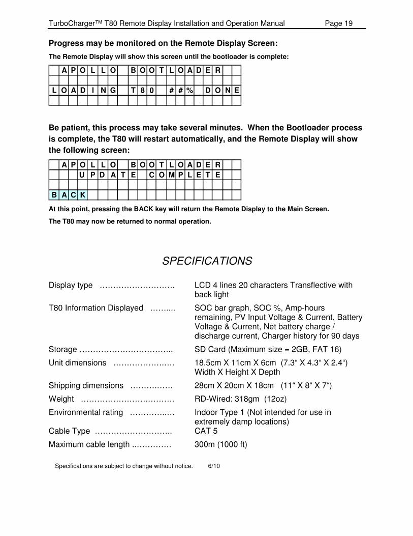
Progress may be monitored on the Remote Display Screen:
The Remote Display will show this screen until the bootloader is complete:
A P O L L O B O O T L O A D E R
L O A D I N G T 8 0 # # % D O N E
Be patient, this process may take several minutes. When the Bootloader process
is complete, the T80 will restart automatically, and the Remote Display will show
the following screen:
A P O L L O B O O T L O A D E R
U P D A T E C O M P L E T E
B A C K
At this point, pressing the BACK key will return the Remote Display to the Main Screen.
The T80 may now be returned to normal operation.
SPECIFICATIONS
Display type ………………………. LCD 4 lines 20 characters Transflective with back light
T80 Information Displayed …….... SOC bar graph, SOC %, Amp-hours remaining, PV Input Voltage & Current, Battery Voltage & Current, Net battery charge / discharge current, Charger history for 90 days
Storage …………………………….. SD Card (Maximum size = 2GB, FAT 16)
Unit dimensions ……………….…. 18.5cm X 11cm X 6cm (7.3“ X 4.3“ X 2.4“) Width X Height X Depth
Shipping dimensions ……….…… 28cm X 20cm X 18cm (11“ X 8“ X 7“)
Weight …………………….………. RD-Wired: 318gm (12oz)
Environmental rating …………..… Indoor Type 1 (Not intended for use in extremely damp locations)
Cable Type ……………………….. CAT 5
Maximum cable length ..…………. 300m (1000 ft)
Specifications are subject to change without notice. 6/10

TurboCharger™ T80 Remote Display Installation and Operation Manual Page 20
Five Year Limited Warranty Information
Warranty and Conditions
Apollo Solar Inc. warrants that the TurboCharger™ T80 Remote Display(s) it manufacturers will be free from defects in materials and workmanship for a period of five (5) years subject to the conditions set forth below:
⇒ This limited warranty is extended to the original user and is non-transferable.
⇒ The limited warranty term begins on the date of invoice to the original user of the product. If no invoice is available the warranty term begins on the date of manufacture as recorded by the serial number of the unit.
⇒ The limited warranty does NOT apply to any product or part thereof damaged or made inoperable by: Operation or installation contrary to the Remote Display manual, alteration or disassembly, reverse polarity, accident or abuse, corrosion, lightning damage, or repair or service provided by an unauthorized repair facility. .
Apollo Solar’s liability for any defective Remote Display or any part thereof shall be limited to the repair or replacement of the unit, at Apollo Solar’s discretion. This warranty is limited to the Remote Display and in no way extends to cover the workmanship of any individual or firm installing the product.
How to Get Warranty Service
This warranty requires that all equipment suspected of being defective in either materials or workmanship be returned to Apollo Solar or its designated service agents. During the five year warranty period products covered under this warranty will be repaired or replaced with equivalent equipment at the discretion of Apollo Solar.
⇒ All products submitted for warranty service must have an RMA number.
To obtain an RMA (return merchandise approval) number, a return shipping address and/or more information about your limited warranty contact Apollo Solar by phone 203 790 6400 or by email at [email protected]
⇒ Mark all parcels sent for service with RMA number.
Send all equipment approved for warranty service in original or equivalent packaging. All inbound freight must be fully pre-paid, no items will be accepted for service with collect or COD freight charges.
Replaced or repaired equipment will be shipped to the address associated with the RMA number. Freight charges for ground service will be paid by Apollo Solar within the continental United States. Return shipments to other states or US territories or foreign countries will be sent freight collect.
THIS LIMITED WARRANTY GIVES YOU SPECIFIC LEGAL RIGHTS, AND YOU MAY ALSO HAVE OTHER RIGHTS THAT VARY FROM STATE TO STATE (OR JURISDICTION TO JURISDICTION). APOLLO SOLAR’S RESPONSIBILITY FOR MALFUNCTIONS AND DEFECTS IN HARDWARE IS LIMITEDTO REPAIR AND REPLACEMENT AS SET FORTH IN THIS LIMITED WARRANTY STATEMENT. ALL EXPRESS AND IMPLIED WARRANTIES FOR THE PRODUCT, INCLUDING BUT NOT LIMITED TO ANY IMPLIED WARRANTIES OF AND CONDITIONS OF MERCHANTABILITY AND FITNESS FOR PARTICULAR PURPOSE, ARE LIMITED IN DURATION TO THE LIMITED WARRANTY PERIOD SET FORTH ABOVE AND NO WARRANTIES, WHETHER EXPRESS OR IMPLIED, WILL APPLY AFTER SUCH PERIOD. SOME STATES (OR JURISDICTIONS) DO NOT ALLOW LIMITATIONS ON HOW LONG IMPLIED WARRANTY LASTS, SO THE ABOVE LIMITATION MAY NOT APPLY TO YOU. APOLLO SOLAR DOES NOT ACCEPT LIABILITY BEYOND THE REMEDIES SET FORTH IN THIS LIMITED WARRANTY STATEMENT OR LIABILITY FOR INCIDENTAL OR CONSEQUENTIAL DAMAGES, INCLUDING WITHOUT LIMITATION ANY LIABILITY FOR PRODUCTS NOT BEING AVAILABLE FOR USE. SOME STATES (OR JURISDICTIONS) DO NOT ALLOW THE EXCLUSION OR LIMITATION OF INCIDENTAL OR CONSEQUENTIAL DAMAGES, SO THE ABOVE EXCLUSION OR LIMITATION MAY NOT APPLY TO YOU.