re-development at no 8 berrima crescent, umina, nsw
TRANSCRIPT

Re-Development at No 8 Berrima Crescent, Umina, NSW Coastal Engineering Assessment
89024430/R2769 Prepared for Slater Architects 24 Apr 2013

Re-Development at No 8 Berrima Crescent, Umina, NSW – Coastal Engineering Assessment Prepared for Slater Architects
24 Apr 2013 Cardno (NSW/ACT) Pty Ltd Page i rep2769 v2 final.doc Version 2
Cardno (NSW/ACT) Pty Ltd
ABN 95 001 145 035
Level 9 The Forum 203 Pacific Highway
St Leonards NSW 2065 Australia
Telephone: 02 9496 7700 Facsimile: 02 9439 5170
International: +61 2 9496 7700
[email protected] www.cardno.com.au
Document Control:
Version Status Date Author Reviewer Name Initials Name Initials
1 Final 17 May 2012 P.D. Treloar PDT Sara Belgrove SJB
2 Final 24 Apr 2013 P.D.Treloar/S. Belgrove PDT/SJB Chris Beadle CB
"© 2013 Cardno (NSW/ACT) Pty Ltd All Rights Reserved. Copyright in the whole and every part of this document belongs to Cardno (NSW/ACT) Pty Ltd and may not be used, sold, transferred, copied or reproduced in whole or in part in any manner or form or in or on any media to any person without the prior written consent of Cardno (NSW/ACT) Pty Ltd.”
Re-Development at No 8 Berrima Crescent, Umina, NSW – Coastal Engineering Assessment Prepared for Slater Architects
24 Apr 2013 Cardno (NSW/ACT) Pty Ltd Page ii rep2769 v2 final.doc Version 2
TABLE OF CONTENTS
1 INTRODUCTION .................................................................................................................. 1
2 BACKGROUND .................................................................................................................... 2
3 COASTAL ENGINEERING ISSUES ................................................................................... 3
3.1 Wave Overtopping ................................................................................................................................ 3
3.2 Site Levels ............................................................................................................................................ 3
4 COASTAL PROCESS PARAMETERS............................................................................... 4
4.1 General ................................................................................................................................................. 4
4.2 Topography........................................................................................................................................... 4
4.3 Sediment Data ...................................................................................................................................... 4
4.4 Wind Climate ........................................................................................................................................ 4
4.5 Wave Climate ....................................................................................................................................... 4
4.6 Rainfall .................................................................................................................................................. 5
4.7 Astronomical Tides and Storm Surge ................................................................................................... 5
4.8 Sea Level Rise...................................................................................................................................... 5
4.9 Planning Period .................................................................................................................................... 6
4.10 Sediment Budget .................................................................................................................................. 6
4.11 Wave Height and Revetment Armour ................................................................................................... 6
4.12 Long Term Erosion and Beach Recession ........................................................................................... 6
4.13 Wave Set-Up at the Shoreline .............................................................................................................. 7
4.14 Wave Run-Up and Ocean Inundation ................................................................................................... 7
4.15 Storm Water Discharge ........................................................................................................................ 7
5 SUMMARY ............................................................................................................................ 8
6 REFERENCES ..................................................................................................................... 9

Re-Development at No 8 Berrima Crescent, Umina, NSW – Coastal Engineering Assessment Prepared for Slater Architects
24 April 2013 Cardno (NSW/ACT) Pty Ltd Page iii P:\8902_44_Miscellaneous\89024430_8_Berrima_Cr_Umina\Import\Cardno\20130218 Report Copied from Coastal\Report\Rep2769 V2 Final.docVersion 1
TABLES
Table 1 Components of Sea Level Rise Planning Benchmarks (after DECCW, 2009) ..................................................... 5
FIGURES
Figure 1 Locality Plan Figure 2 Ocean Side Boundary, 2 February 2012 Figure 3 Erosion Escarpment and Existing Residence Figure 4 View of Site from Ettalong Creek Entrance to Mount Ettalong Road Figure 5 Seaward End of Existing Revetment
APPENDICES
Appendix A Site Survey Appendix B 1992 Rock Seawall Plan - Indicative Appendix C Proposed Extension of Rock Revetment

Re-Development at No 8 Berrima Crescent, Umina, NSW – Coastal Engineering Assessment Prepared for Slater Architects
24 Apr 2013 Cardno (NSW/ACT) Pty Ltd Page 1 P:\8902_44_Miscellaneous\89024430_8_Berrima_Cr_Umina\Import\Cardno\20130218 Report Copied from Coastal\Report\Rep2769 V2 Final.docVersion 1
1 INTRODUCTION
The owner of 8 Berrima Crescent, Umina Beach, (Mr Paul McCloskey), proposes to redevelop the site and has sought advice from Slater Architects and Cardno (NSW/ACT). Figure 1 shows the location of this site.
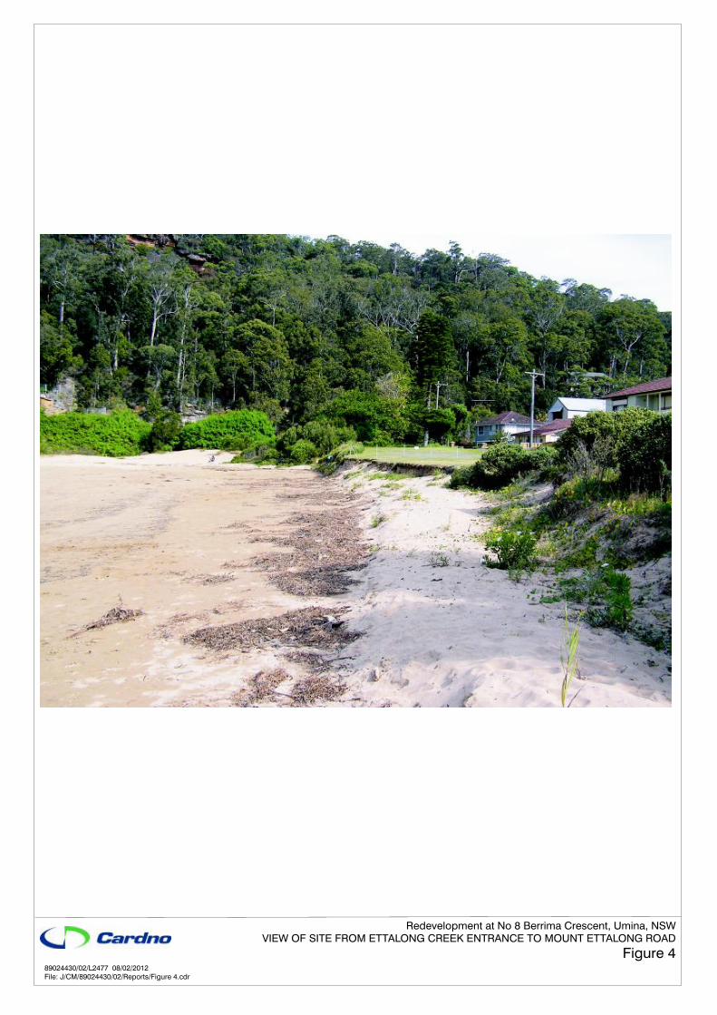
Following a site inspection at 10.00am 2 February, 2012, and discussions with the client, Mr Paul McCloskey, initial advice on coastal engineering issues at the site as they may affect redevelopment plans for the site was prepared. Figure 2 shows Gosford City Council machinery working in the entrance to Ettalong Creek on 2 February 2012. Figures 3 and 4 show other aspects of the site, taken on 16 April 2012. Appendix A provides survey information of the site. It is clear that storm waves can cause significant back-beach erosion at this site. That erosion, in terms of toe level scour, may be exacerbated by flow from Ettalong Creek. – see Figure 2.
This property lies in the Gosford City area. Following the severe storms of the 1970’s, during which significant storm damage occurred to beaches in the then Shire, as well as to some houses, the Shire commissioned the then New South Wales Public Works Department to undertake a coastal hazards study and to provide coastal engineering advice for use in the management of future coastal development. Since that time a range of further investigations have been undertaken, culminating in Gosford City Council’s (GCC) adoption in August, 1995, of the ‘Coastal Management Study and Coastal Management Plan - Gosford City Open Coast Beaches’, (GCC, 1995). Investigations have also been undertaken of the Broken Bay Beaches, including Umina and Ocean Beaches, for GCC by Patterson Britton & Partners, Reference 5. The outcome of those investigations was the adoption of the Coastal Management Plan for the Broken Bay Beaches in 1999.
More recently, GCC have engaged Worley Parsons to undertake a revision of the coastal management plans for all of these beach areas, but it is understood that those plans have not been adopted as yet.
All coastal developments must be undertaken according to the guidelines of these plans and submissions to GCC for coastal development must include a coastal engineering report.

Re-Development at No 8 Berrima Crescent, Umina, NSW – Coastal Engineering Assessment Prepared for Slater Architects
24 Apr 2013 Cardno (NSW/ACT) Pty Ltd Page 2 P:\8902_44_Miscellaneous\89024430_8_Berrima_Cr_Umina\Import\Cardno\20130218 Report Copied from Coastal\Report\Rep2769 V2 Final.docVersion 1
2 BACKGROUND
Following an examination of correspondence between the previous owner, present owner, Mr McCloskey, and Council, (circa 1998 – 2001). Cardno understands that within the current Broken Bay Beaches Coastal Management Plan adopted by Council that it is/was intended to complete the rock revetment that was partially built in the 1990’s along the ‘southern creek bank’, but terminated through a lack of funds – Cardno’s understanding.
Figure 5 shows the terminating point of this rock revetment and Appendix B shows the original design plans. Figure 1 indicates its plan alignment also. The cross-section at chainage 785m shows that the rock revetment was built at a slope of 1:1 with a crest level of 2.5m AHD – though the plans do not show a vertical datum, hence inferred. No details of rock size or geotextile fabric are shown on these plans. Inspection on site suggests that the rocks are typically about 0.4m diameter, but irregular. Toe level is at 0m AHD, which would not be deep enough for the ocean-side section of the wall. The slope of 1:1 would also be too steep.
The remaining length of the wall is intended to be constructed in two sections. The first of these sections (Appendix C, green line) would need to be constructed by the owners whose land lies landward of this line – which in fact is solely Mr McCloskey. The second section (blue) would protect public land and would be built by Council (not necessarily at the same time). Mr McCloskey intends to construct all of the wall within his property. Additional investigations may be required should Council not proceed with their component of the revetment wall sequentially with Mr McCloskey’s works.

Re-Development at No 8 Berrima Crescent, Umina, NSW – Coastal Engineering Assessment Prepared for Slater Architects
24 Apr 2013 Cardno (NSW/ACT) Pty Ltd Page 3 P:\8902_44_Miscellaneous\89024430_8_Berrima_Cr_Umina\Import\Cardno\20130218 Report Copied from Coastal\Report\Rep2769 V2 Final.docVersion 1
3 COASTAL ENGINEERING ISSUES
3.1 Wave Overtopping
Council’s current development requirements at this site stipulate that all new development lies behind the 2045 hazard line, (GCC, 1995). Additionally, floor levels must be set at a level that is defined by the so-called 100-years ARI ocean storm wave run-up (R2) level, including 0.9m sea level rise (projected SLR to 2100) in this calculation, and 0.5m freeboard, (DECCW, 2009).
On the basis that the rock revetment will be built by Mr McCloskey as part of this redevelopment (green section of revetment on the Appendix C plan), the erosion hazard-line becomes the rear of this revetment wall. Hence no piles are required in terms of coastal erosion effects for proposed structures; but may be required for the structural footing design.
Cardno have applied their Broken Bay/Brisbane Water numerical wave model to determine nearshore wave parameters and then wave run-up estimation at this site – including the projected 0.9m SLR for 2100. Offshore wave conditions equivalent to 100-years ARI (Hs = 10m, SSE to E tested – conservative wave height) were applied. The outcome of this is that peak storm significant wave height (Hs) is 1.5m with a period (Tz) of 10.5 seconds in the near shore region of this site. Based on the Holman wave run-up relationship, potential wave run-up (R2) was estimated to be 3.1m AHD – including 0.9m SLR in the calculation. This wave would therefore overtop the back-beach area and propagate to likely buildings. The rate of overtopping was estimated following Eurotop 2007, assuming a near vertical erosion scarp at the back-beach, see Figure 3. This overtopping water would propagate intermittently with maximum depths of 0.2m beyond the scarp/revetment. Hence, finished floor levels would need to be set at 3.2m AHD (2.5m AHD to 0.2m + 0.5m) for habitable areas. Overtopping would likely be less for the developed rock revetment because of the roughness on the outer face.
3.2 Site Levels
There is some variation in site levels – which are nominally 2.5m AHD. Council currently opens the entrance to Ettalong Creek during wet periods, see Figure 2. Mr McCloskey has previously discussed removal of some of the accumulated sand within the creek mouth at his expense to improve conveyance. Some of this sand could be removed in order to improve the conveyance of the downstream waterway and then used to level this site and back-fill behind the proposed section of revetment. If used as fill or back-beach renourishment it may need to be tested and may be found to be unsuitable to be used (effectively) as beach renourishment.

Re-Development at No 8 Berrima Crescent, Umina, NSW – Coastal Engineering Assessment Prepared for Slater Architects
24 Apr 2013 Cardno (NSW/ACT) Pty Ltd Page 4 P:\8902_44_Miscellaneous\89024430_8_Berrima_Cr_Umina\Import\Cardno\20130218 Report Copied from Coastal\Report\Rep2769 V2 Final.docVersion 1
4 COASTAL PROCESS PARAMETERS
4.1 General
The parameters to be investigated for coastal developments in the Gosford City region are generally as follows.
4.2 Topography
Wave generation and penetration to the foreshore at this site are governed by the coastal topography – waterway depths, presence of islands and fetch distances. This matter has been addressed specifically for this site – see Section 3.
4.3 Sediment Data
No sediment data has been collected at this site. Should sand fill be required to backfill behind the proposed extension to the rock revetment, then sand of particle size similar to that on the beach should be used, and preferably of similar colour. Note that Figures 3 and 4 show that the site is not formed from all dune sand, with some soil used to level the site and for landscaping. A deep rock sub-base may underlie the property, based on the general characteristics of the region, but is unlikely to affect construction of the proposed rock revetment.
4.4 Wind Climate
Local wind is only of importance, from the coastal engineering point of view, when sand losses from the frontal dune or beach are of concern. This may lead to tunnelling of winds, deterioration of the dune system as an ocean protective agent and nuisance sand deposits against walls.
It is noted that the site is well vegetated and maintained and this is not an issue at this site.
4.5 Wave Climate
Design wave and water level parameters for this site have been discussed in Section 3. Waves that approach the shoreline are limited by the available water depth (and offshore wave steepness). Hence, only at high tide (including storm tide and SLR), will larger waves be able to impinge on the existing and proposed revetment faces. However, at other times, waves may damage the toe areas of these structures or the back-beach itself.
Water depth and beach levels are caused to vary by scour, tide, storm surge and wave set-up. At this site wave-caused scour to -1m AHD and a design still water level (storm tide) of 2.4m AHD (0.9m SLR included) have been defined. Indian Springs Low Water Tide level (approximately lowest astronomical tide) is about -0.9m AHD at this site.

Re-Development at No 8 Berrima Crescent, Umina, NSW – Coastal Engineering Assessment Prepared for Slater Architects
24 Apr 2013 Cardno (NSW/ACT) Pty Ltd Page 5 P:\8902_44_Miscellaneous\89024430_8_Berrima_Cr_Umina\Import\Cardno\20130218 Report Copied from Coastal\Report\Rep2769 V2 Final.docVersion 1
4.6 Rainfall
Rainfall is not particularly important, but the property owner and his architect/engineer must ensure that surface runoff is properly directed into the Council storm water run-off system. This requirement is necessary to avoid scour to the surrounding areas during severe storms. By maintaining adequate vegetation the owner will ensure that little damage will ever occur.
This requirement appears to be fulfilled.
4.7 Astronomical Tides and Storm Surge
Storm surge is the combination of wind set-up and the inverse barometer effect. When combined with a spring tide, higher water levels than would normally occur will be observed. A storm tide level of 1.5m AHD has been specified for this site in present day conditions. Projected SLR by 2100 of 0.9m has been included in the design water level and wave overtopping calculations.
4.8 Sea Level Rise
A number of leading international scientists believe that there will be an increase in the Earth's temperature over the next 50 to 100 years. This increase will be caused by increasing carbon di-oxide levels in the atmosphere and has been called the Greenhouse Effect. There is likely to be an increase in the temperature of the oceans which will lead to a gradual rise in MSL as a result of ocean water expansion.
In 2009, The Department of Environment, Climate Change and Water (DECCW, now OEH) advisd that all coastal developments must be undertaken in the knowledge that a potential sea level rise may occur. That is, such developments should provide scope for protective measures should such a rise in MSL occur.
DECCW , in planning for climate change, produced a Sea Level Rise Policy Statement (DECCW, 2009) that set SLR planning benchmarks of 0.4m by 2050 and 0.9m by 2100 (relative to 1990 mean sea levels). These benchmarks were derived from both Intergovernmental Panel on Climate Change (IPCC) projections and CSIRO research. The manner in which they were calculated incorporates a range of variables, as shown in Table 1. The SLR component is derived from the IPCC SRES A1F1 climate change scenario due to the fact that, in the last decade, the observed global average of sea level from tide gauges and satellites is tracking along the upper bound of the IPCC projections.
Table 1 Components of Sea Level Rise Planning Benchmarks (after DECCW, 2009) Component 2050 2100 SLR 30 cm 59 cm Accelerated ice melt (included above) 20 cm Regional SLR variation 10 cm 14 cm Rounding* - -3 cm Total 40 cm 90 cm
Re-Development at No 8 Berrima Crescent, Umina, NSW – Coastal Engineering Assessment Prepared for Slater Architects
24 Apr 2013 Cardno (NSW/ACT) Pty Ltd Page 6 P:\8902_44_Miscellaneous\89024430_8_Berrima_Cr_Umina\Import\Cardno\20130218 Report Copied from Coastal\Report\Rep2769 V2 Final.docVersion 1
The legislative amendments associated with stage one of the NSW Government's coastal reforms commenced on 21 January 2013. As part of these reforms, the NSW Government announced that councils would have the flexibility to determine their own sea level rise projections to suit their local conditions - the Government would no longer prescribe state-wide sea level rise projections for use by councils. As such, The 2009 NSW Sea Level Rise Policy Statement is no longer NSW Government policy. Gosford City Council, on their website (http://www.gosford.nsw.gov.au/environment/sea-level-rise/) indicates that they still adopt 0.9m as its sea level rise planning level for the year 2100.
A sea level rise of 0.9m to 2100 has been adopted for revetment design criteria and wave run-up level calculation.
4.9 Planning Period
A planning period of 100-years is implicitly adopted by setting the sea level rise to be 0.9m for 2100. There is some evidence of long term shoreline recession and erosion at this site.
4.10 Sediment Budget
Construction of the proposed revetment will alleviate any underlying shoreline recession, as well as future recession that would be caused by projected SLR.
4.11 Wave Height and Revetment Armour
Design wave parameters at this site are Hs=1.5m and Tz = 10.5 seconds. At high water levels there is very little modification of these waves as they approach the shoreline. Application of van der Meer’s (1990) relationships leads to a median rock size of about 0.7m to 1.4m (2.5 to 7 tonnes) being suitable for construction of the new wall. This assumes igneous rock and a low porosity structure and a crest level to 2.6m AHD – marginally above the site level. A total storm duration of 12 hours and damage factor of 2% were adopted, together with a slope of 1V:1.5H. This is steeper than the existing wall, but is more common in wave environments. It should be possible to merge this slope with the end of the existing wall. Setting toe level to be -1.5m AHD will require in the order of 3m of sand excavation for construction.
It is important to note that storms more severe than the 100-years ARI storm may occur during a 50 or 100-years planning period. However, the relationship between wave height and average recurrence interval at this site is restricted by the nearshore breaking wave depths and storm tide levels. On this basis it is not expected that significantly more overtopping damage would occur during a less frequent, more severe storm near the site than would occur during the 100-years storm.
4.12 Long Term Erosion and Beach Recession
It is likely that there is a gradual long term loss of sand at this site, but the proposed rock revetment will prevent further shoreline retreat. The proposed revetment walls would not increase sand losses and would not affect neighbouring properties.

Re-Development at No 8 Berrima Crescent, Umina, NSW – Coastal Engineering Assessment Prepared for Slater Architects
24 Apr 2013 Cardno (NSW/ACT) Pty Ltd Page 7 P:\8902_44_Miscellaneous\89024430_8_Berrima_Cr_Umina\Import\Cardno\20130218 Report Copied from Coastal\Report\Rep2769 V2 Final.docVersion 1
4.13 Wave Set-Up at the Shoreline
Wave set-up occurs shoreward of the breaker zone as a result of conversion of wave kinetic energy into potential energy and the need to conserve momentum flux. Wave set-up combines with tide and storm surge to cause a total elevated water level. A wave set-up height of about 0.8m could occur against the rock revetment at this site. This increase in water level is included implicitly in the wave run-up calculations.
4.14 Wave Run-Up and Ocean Inundation
Another potential source of damage is through wave run-up and overtopping of the proposed back-beach area - revetment. Section 3.1 discusses this process in detail.
4.15 Storm Water Discharge
Design and construction of the proposed new revetment should accommodate the estimated runoff from the grassed areas on this property.
Figure 2 shows that Ettalong Creek can meander south and along the property boundary. The land level at the top of the property is about 2.5m AHD. The total height of the two erosion escarpments is about 3m. Hence the level of the sand in the lower scoured channel is about -0.5m AHD. The toe of the proposed rock revetment has been set at -1.5m AHD. Scour to levels lower than this is unlikely. During a rare severe flood, the scour channel is not as likely to occur near this part of the wall because the flow will be more directly seaward as a result of its momentum.
Note that in the creek the toe of the existing wall is only to 0m AHD and has not been damaged, possibly because the momentum of flood flows tends to affect the northern side of the creek more than the southern side where there are significant sand deposits.
Re-Development at No 8 Berrima Crescent, Umina, NSW – Coastal Engineering Assessment Prepared for Slater Architects
24 Apr 2013 Cardno (NSW/ACT) Pty Ltd Page 8 P:\8902_44_Miscellaneous\89024430_8_Berrima_Cr_Umina\Import\Cardno\20130218 Report Copied from Coastal\Report\Rep2769 V2 Final.docVersion 1
5 SUMMARY
This report has addressed a range of coastal/estuarine engineering issues that must be considered for coastal developments in the Gosford City area. These issues have included seabed topography, wind, waves, rainfall, water levels, sea level rise to 2100, the 100-years planning period, long term shoreline recession and storm demand. None of these is likely to have a future impact on the existing dwelling within the planning period. However, some storm erosion has occurred already at the site and would continue; and with projected SLR, wave overtopping becomes more likely, with some seawater propagating to the existing buildings.
It is proposed that the originally proposed revetment shown in Appendix C be completed, partially by the owner and partially by GCC (in due course) for the private and public property areas, respectively. Details of the revetment design are:-
Rock armour, igneous preferred, SG 2.6, 2.5 to 7 tonnes, placed in two layers – but sandstone could be used to be consistent with the existing wall, but must be free of cracks, two layers
Slope 1V:1.5H
Crest level 2.6m AHD, toe level -1.5m AHD
Sand back-fill may be required – to be similar to the native sand
Suitable geotextile fabric to be used and properly held in place
Provision is to made for runoff from the site and wave overtopping water to discharge back to sea
From a coastal engineering point of view, the existing or any future proposed revetment works will cause minimal interference to normal coastal processes now, and in the foreseeable future. The development would have no effect on adjoining properties. A future very severe storm would cause some minor inundation of the site and floor levels must equal or exceed 3.2m AHD – noting that creek flood levels must be considered also. The site may be affected partially by contaminated water in a future very severe storm.
The owner is advised to maintain reasonable vegetation cover to prevent windblown soil losses.
All storm water from buildings is to be directed to Council’s storm water system.

Re-Development at No 8 Berrima Crescent, Umina, NSW – Coastal Engineering Assessment Prepared for Slater Architects
24 Apr 2013 Cardno (NSW/ACT) Pty Ltd Page 9 P:\8902_44_Miscellaneous\89024430_8_Berrima_Cr_Umina\Import\Cardno\20130218 Report Copied from Coastal\Report\Rep2769 V2 Final.docVersion 1
6 REFERENCES
Eurotop – Wave Overtopping of Sea Defences and Related Structures: Assessment Manual. Published by Environment Agency, UK, Expertise Netwerk Waterkeren, NL and Kuratorium fur Forschung im Kusteningenieurwessen, DE
Gosford City Council (1995) Coastal Management Study and Coastal Management Plan - Gosford City Open Coast Beaches.
DECCW (2009) NSW Sea Level Rise Policy Statement. NSW Department of Environment, Climate Change and Water.
IPCC (2007) Climate Change 2007: Synthesis Report. An Assessment of the Intergovernmental Panel on Climate Change. IPCC: Geneva, Switzerland.
Patterson Britton & Partners Pty Ltd (1999): Broken Bay Beaches, Coastal Management Plan. Report Prepared for Gosford City Council.
Van der Meer, J W (1990): Static and Dynamic Stability of Loose Materials. In: K Pilarczyk (editor), Coastal Protection. Balkema, Rotterdam.

24 Apr 2013 Cardno (NSW/ACT) Pty Ltd Page 1 P:\8902_44_Miscellaneous\89024430_8_Berrima_Cr_Umina\Import\Cardno\20130218 Report Copied from Coastal\Report\Rep2769 V2 Final.docVersion 1
Figure 1 Locality Plan Figure 2 Ocean Side Boundary, 2 February 2012 Figure 3 Erosion Escarpment and Existing Residence Figure 4 View of Site from Ettalong Creek Entrance to Mount Ettalong Road Figure 5 Seaward End of Existing Revetment
Figures


24 April 2013 Cardno (NSW/ACT) Pty Ltd Page A1 P:\8902_44_Miscellaneous\89024430_8_Berrima_Cr_Umina\Import\Cardno\20130218 Report Copied from Coastal\Report\Rep2769 V2 Final.docVersion 1
Appendix A
Site Survey


24 April 2013 Cardno (NSW/ACT) Pty Ltd Page A1 P:\8902_44_Miscellaneous\89024430_8_Berrima_Cr_Umina\Import\Cardno\20130218 Report Copied from Coastal\Report\Rep2769 V2 Final.docVersion 1
Appendix B
1992 Rock Seawall Plan - Indicative


24 April 2013 Cardno (NSW/ACT) Pty Ltd Page A1 P:\8902_44_Miscellaneous\89024430_8_Berrima_Cr_Umina\Import\Cardno\20130218 Report Copied from Coastal\Report\Rep2769 V2 Final.docVersion 1
Appendix C
Proposed Extension of Rock
Revetment
