reactionless control for two manipulators mounted on a cable … · 2013-12-12 · reactionless...
TRANSCRIPT

Reactionless Control for two Manipulators Mounted on a
Cable-Suspended Platform
Roberto Lampariello∗, Johann Heindl∗, Ralf Koeppe∗∗, Gerd Hirzinger∗
∗Institute of Robotics and Mechatronics ∗∗KUKA Roboter GmbH
German Aerospace Center (DLR) 86165 Augsburg, Germany
82234 Weßling, Germany [email protected]
Abstract— The dynamics and control of a cable-suspended,two-arm robotic system are developed for an entertainmentapplication. One manipulator arm is controlled to fulfill a userdefined task. The second arm is then controlled to compensatefor the disturbances on the cable-suspended platform arisingfrom the motion of the first.
Model-based feedforward control, stemming from themomentum conservation equations of a free-floating robot, isdeveloped for the motion compensation problem. Furthermore,due to model uncertainty, sensor-based feedback control isintroduced, to account for undesired oscillatory motions of thesystem. The latter control problem reduces to the dissipationof the oscillatory energy of the system, by means of adequaterobot control. Both control methods are implemented andtested on an experimental set-up.
I. INTRODUCTION
Cable-suspended robots have a wide application for ma-
nipulation in large workspaces and where actuation needs
to be performed on targets difficult to reach from ground.
Examples include inspection and repair in shipyards or trans-
port of externally suspended loads on helicopters [1], [2].
The problems of path tracking and of oscillation damping
are then of interest. Control may be performed with direct
actuation of the suspension cables [1], [2], or as proposed
here, with a momentum compensating element, such as a
suitably actuated mass. A particular case is that of using a
robot manipulator. This adds interesting aspects, related to
entertainment robotics and to multiple-arm free-floating robot
control.
This work develops a control method for a cable-
suspended, two-arm robotic system, thought for an entertain-
ment application. Two six-degree-of-freedom manipulators
are mounted on the opposite faces of a suspended platform,
parallel to the ground (see Fig. 1). The goal of the control
is to allow one robot, the master, to perform a user-defined
six-degree-of-freedom tracking task, such as dusting a car
positioned on an elevated platform beneath it. The second
robot, the slave, then compensates for any disturbances on
the platform which arise from the motion of the master.
The desired end result is that the platform remains stationary
during robot operation.
Fig. 1. Experimental set-up of two-arm cable-suspended system: the masteris provided with a long duster, the slave with a heavy dumbbell
This control problem has two main components: the first
relates to the ideal motion compensation of the two robots,
which can be solved with a model-based approach and free-
floating robot dynamics; the second relates to the suppression
of the system oscillations, which here may arise from model
uncertainty or implementation errors, solved with feedback
control.
The developed control method is applied to the experimen-
tal set-up shown in Fig. 1. The two 6 d.o.f. robot arms have a
distinctive upper/lower elbow arm structure, giving rise to a
compensation problem also recognized in [3] to be difficult.
The added complexity arising from the oscillatory motion
element, is treated with a control law based on passivity.
The paper is divided into four subsections: the first de-
scribes some related bibliography, the second the theoretical
aspects of the control methods, the third the implementation
aspects with a description of the experimental set-up and the
1-4244-0259-X/06/$20.00 ©2006 IEEE

fourth the experimental results. The paper is closed with a
conclusions section.
II. BIBLIOGRAPHY
Some works of relevance to the compensation control
problem include those on free-flying robot dynamics, as in [4]
and [5]. In the first, a spatial dynamic model for a multiple-
arm free-flying robot with reaction wheels is derived. Motion
control of the 6 d.o.f. arms is then addressed, operating one to
trace a given path and a second to minimize the operational
control torque of the reaction wheels, to maintain the attitude
of the base body fixed. The formulation of the solution
is based on the inverse kinematics on acceleration level.
In [5], the full planar compensation problem is considered
for a robot with two three-joint arms also extending in the
plane. The momentum conservation equations are used and
emphasis is given to avoiding singularities of the compen-
sating robot. However, in all cases the joint kinematic and
dynamic constraints, which strongly limit the workspace of
the compensating robot, are not addressed.
In [6] the inverse kinematics problem for a single-arm free-
flying system is analyzed in detail, based on a momentum
conservation formulation, although again only attitude motion
of the spacecraft is of interest. On the vibration suppression
by means of a robot, in [3] the problem of end-effector path
tracking and of vibration suppression for macro-mini manipu-
lators is addressed. In both cases, solutions are provided with
use of the robot reaction null space, which is not applicable
here since the tasks of the master robot are generally six-
dimensional.
III. METHOD
The equations of motion of a two-arm free-floating robot
are first described. For the purpose of the motion compensa-
tion control problem, these are then related to the momen-
tum conservation equations for the equivalent system. The
equations of the cable suspended system are then formally
described. Finally, based on these derivations, the theory for
both aforementioned control problems is presented.
A. Equations of motion
1) Dynamic equations of the free-floating system: Con-
sider the system depicted in Fig. 2. The inertial frame of
reference is denoted by {OI , eI}. Its relation to the platform
body frame of reference {O0, e0} is described by the position
vector r0 and the orientation matrix A0, parameterized for
example by Euler angles φ 0 = [φ01, φ
02, φ
03], and such that
e 0 = A 0 e I . Vector quantities are here expressed in the
inertial coordinate frame, such that for example r0 = r0 e I .
The configuration of the ith robot is described by the
column matrix θi, the elements of which describe the jth
revolute joint position θ ji , measured relative to an arbitrary
initial reference configuration.
Platform
Master
Slave
{ , }OI I
e
{ , }O0 0
e
{ , }Oj
i iej
r0
A0
qj
i
Fig. 2. Configuration and reference frames of the cable-suspended robot
Considering now the free-floating robot dynamics, i.e.
omitting gravity and the suspension cables, let the platform
state variables be collected as follows:
yI = [ r0, φ0] T yII = [ v0, ω0] T , (1)
where yI and yII are the position and velocity state vari-
ables respectively. The formal equation structure can then be
written as follows [4]:
Mp Mpr1Mpr2
MTpr1
Mr1Mr1r2
MTpr2
MTr1r2
Mr2
yII
θ1
θ2
+
Cp
Cr1
Cr2
=
0
τ 1
τ 2
or
M
yII
θ1
θ2
+ C = τ , (2)
where M is the configuration dependent inertia matrix, C the
configuration dependent vector of centrifugal and Coriolis
terms and τ the vector of external actions acting on the
degrees of freedom yI ,θ1,θ2 of the whole system. Further-
more, the subscripts p, r1 and r2 relate to the platform, the
master robot and the slave robot respectively, such that, for
example, Mp ∈ R(3×3) is the inertia matrix which relates to
the platform.
It is convenient here to bring out the dynamic coupling
between the robots and the platform. As such, from Eq. (2)
it follows that:
Mp yII + Cp = −Mpr1θ1 − Mpr2
θ2 . (3)
2) Linear and angular momentum equations: Consider
now again the case where gravity and the cables are absent.
This is the free-floating case seen above, for which the laws

of conservation of linear and angular momentum yield the
following relationship between the platform and the robot
velocities [4]:
Mp
[
v0
ω0
]
= −Mpr1θ1 − Mpr2
θ2 , (4)
assuming zero initial momentum. This equation, which is first
integral of Eq. (3), can be rewritten as:[
v0
ω0
]
= J1 θ1 + J2 θ2 , (5)
where Ji is a Jacobian matrix of the ith manipulator, relating
base body and joint motion.
3) Dynamic equations of the cable-suspended system:
Finally, introducing now the cables and gravity, the final
equations of the system formally become:
Mp yII + Cp = −Mpr1θ1 −Mpr2
θ2 + G + Fc , (6)
where the time dependent matrix G represents the gravity
force vector and Fc the vector of cable forces (always
positive) respectively.
For the resolution of these equations, useful for simulation
purposes, the cables can be modeled as elastic springs. How-
ever, the dynamics of the cables elasticity is not of interest
here, as it is assumed that their elongation is negligible.
Suitable choice of the stiffness parameters in the spring
model will give the desired physical behavior, although the
resulting numerical stiffness of the equations leads to long
computational times.
Note that the above formulations are also useful for the fact
that the robots are controlled through their built-in industrial
controllers. As such, the control commands are designed at
a joint velocity level, rather than at a torque level. This gives
rise to delays in the controller performance, as described in
the results section.
B. Feedforward Compensation Control
For the compensation control problem, the system may be
idealized as free-floating. The assumption is in fact made
that it is initially at rest. In case of perfect knowledge of the
system parameters, a reactionless motion of the two robots
can be determined with a model-based approach. In fact, if
the slave robot can perfectly compensate for the actions of
the master on the platform, then the latter will ideally always
remain stationary. Any diversion from this is therefore seen
as an error, to be compensated with the feedback control
action described in section III-C.
1) Free-floating system: Following is the description of
the compensation motion control for the general uncon-
strained case. Consider the conservation of the linear and
angular momentum of a free-floating system, expressed in
Eq. (4). The solution to the six-dimensional motion compen-
sation problem, where θ1 = θ1(t) is an assigned function in
time, is given by the condition:[
v0
ω0
]
= 0 (7)
and Eq. (4) simply yields:
θ2sol = − Mpr2
−1 Mpr1θ1 . (8)
Such a solution always exists as long as matrix Mpr2is non
singular. As we will see, however, the physical constraints on
the system (joint actuation limits) are such that only a very
limited set of these solutions are practically feasible.
2) Constrained free-floating system: For the constrained
cable-suspended system, the formulation is modified as fol-
lows. Since, by applying suitable operational constraints on
the robots, the platform is constrained in the vertical transla-
tional and in the horizontal in-plane rotational motions, either
by the cables, or by the weight of the entire system, then only
the remaining degrees of freedom need to be compensated
for. In fact, for the vertical translational motion, the robot
inertial forces on the platform would have to overcome the
weight of the system (see Eq. (6)). Likewise, for the in-
plane rotational motions, the robot inertial moments about
a given pivoting side of the platform would have to exceed
that generated by the weight of the system. Due to the large
mass of the experimental system used, these limitations turn
out to be very unrestrictive and were therefore ignored.
To solve the constrained compensation control problem,
Eq. (4) can then for example be written as follows:
[3 × 3]M′
v0x
v0y
ω0z
= −[3 × 6]Mpr1
′
θ1 − [3 × 6]Mpr2
′
θ2 ,
(9)
where the primed matrices have been obtained by the rela-
tive terms in their fully six-dimensional counterparts (their
dimensions are defined by the lower left-subscript). In this
example, all joints of the slave robot are used (more will be
said about this point in subsection III-B.4). Therefore, setting
the left-hand side to zero, as required, gives rise to a least
squares problem.
3) Full quadratic programming formulation: In practice,
kinematic and dynamic supplementary constraints on the
slave robot motion enter into the problem. These are inequal-
ity constraints, which relate to the joint positions, velocities
and accelerations. A quadratic programming problem can
then be formulated, where the kinetic energy of the slave
robot Γ is to be minimized:
minθ2
Γ(θ2) =1
2θ2
T Mr2θ2 , (10)
where Mr2is the slave robot inertia matrix, and with equality
and inequality constraints as follows:
Mpr1
′
θ1 + Mpr2
′
θ2 = 0 (11)

θ i2 min ≤ θ i
2 ≤ θ i2 max (12)
θ i2 min ≤ θ i
2 ≤ θ i2 max (13)
θ i2 min ≤ θ i
2 ≤ θ i2 max . (14)
The joint positions and accelerations can be linearly related
to the velocities by simple numerical integration or differen-
tiation, i.e.
θ i2(t) = θ i
2(t − ∆t) + θ i2(t) ∆t (15)
θ i2(t) = (θ i
2(t) − θ i2(t − ∆t))/∆t , (16)
where ∆t is equal to the sampling rate of 12 ms. As such,
for the given optimization problem, the optimal solution θ∗
2
is unique, since the matrix Mr2is positive definite [8]. This
solution locally minimizes the weighted norm of the joint
velocities, implying that no internal motions result.
4) Compensation limit and kinematic decoupling of the
slave robot: It turns out that the physical bounds on the
slave robot joints make the range of master motions which
can be compensated rather limited. This is due to the robot
kinematic configuration, which gives rise to a strong coupling
in the joint motions for the actions exerted at the base.
Practically, compensating forces or torques alone is simple,
but compensating both simultaneously is not. Nenchev also
points this out in [3].
This fact can be simply viewed as follows. Consider first
the case in which only the first three joints of the slave
robot are used, for which now Mpr2
′
∈ R(3×3) in Eq. (11),
which for our purpose would simply need to be inverted.
Furthermore, if we imagine to have a sliding disk in place
of the slave robot, actuated in the two translational degrees
of freedom of interest, and which is also allowed to rotate
about its axis of symmetry, then the same matrix would be
diagonal and the compensation limit would be decoupled for
each direction. This could actually be an interesting hardware
implementation for different industrial applications of this
robotic system. Instead, for the robot kinematics shown in
Fig. 3, where the first joint is revolute, matrix Mpr2
′
includes
off-diagonal elements, which give rise to the strong joint
coupling.
A judicious initial slave robot configuration is a first
measure to improve the solution of the inverse kinematics
problem. This can be chosen by the condition:
minθ2
κ =σ1
σ2, (17)
where κ is the condition number of matrix Mpr2
′
, while σ1
and σ2 its largest and smallest singular values respectively.
This favors a well-conditioned inverse, for the resolution of
Eq. (11).
A further development involves the decoupling of the slave
robot kinematics. This in turn involves choosing a particular
configuration of the wrist joints. In fact, by selecting joint 5
Fig. 3. Kinematics of KUKA robot
such that joint 6 is always aligned with the vertical, i.e. (see
also Fig. 3)
θ52 = −θ2
2 − θ32 θ4
2 = 0 , (18)
ensures that the latter’s action only applies to the rotational
degree of freedom of the platform. This way, joints 1,2 and 3
can be applied to compensate for the translation disturbances
on the system and the decoupled joint 6 can then deal with
the remaining rotational element.
Mathematically the solution is as follows. Let Eq. (11) now
become
[3 × 6]Mpr1
′
θ1 + [3 × 4]Mpr2
′′
[1 × 4]θ2
′
= 0 , (19)
where the double-primed matrix Mpr2
′′
has dimensions
(3 × 4) and θ′
2 is a (4 × 1) vector, containing the first
three and the last robot joint velocities (the effect of joint 5
is here neglected for simplicity). The conditions in Eq. (18)
guarantee that the first two rows of Eq. (19) can be solved
independently of θ62 , giving a solution for joint velocities
θ12, θ
22 and θ3
2 . Then, the last row of Eq. (19), which includes
all terms of θ′
2, can be solved in θ62 for the previously found
solution of the first three joints. As will be shown in the
results section, this configuration was found to be successful
for a wider range of motions of the master robot.
Equations (10)-(14) (or (19) in place of (11)) can be solved
for subsequent time steps to obtain a solution for a given
master robot motion. The solution can be used to partly
validate the feasibility of the compensation, with respect to
the motion constraints. The global optimization of kinematic
redundancy was however not addressed here.
C. Feedback Oscillation-Suppression Control
The solution in the previous section is only suitable for
feedforward control. A feedback control is necessary to
account for modeling and implementation errors during the
execution of the task which, due to the effect of gravity,
give rise to an undesired oscillatory motion of the platform.
The feedback error then consists of the platform motion, the
measurements of which are provided by a camera system

placed above it.
Here, the aim of the controller is to add any necessary
compensation, via extra slave robot actuation, to account for
the platform motion disturbance. We first consider the simpler
case where the slave robot only has to dissipate the energy
of the system initially set in oscillation. Then, the extension
to the dual task of compensating for the master robot as well
as the oscillation suppression is addressed.
Let us then analyze the first problem in the framework of
passive systems and consider the specific case of passivity-
based position control, as described in [7]. The Hamiltonian
of the platform is
Hp =1
2yI
T Mp yI + U(yI) , (20)
where yI and yI represent the platform position and velocity
states respectively (cf. Eq. (1)), Mp its inertia matrix (cf.
Eq. (6)) and U(yI) its potential energy (this includes the
gravity force term G and the term of cable forces Fc).
It is straightforward to state that the platform is in itself
a passive system. In fact, Eq. (20) shows that its total
energy has a bounded minimum in the stationary position
of interest, since the potential energy is referenced to an
arbitrary constant. This position, without loss of generality,
may be given by r 0 = 0,φ 0 = 0, for which the gravity
force term G is zero. Furthermore, if the condition holds
that v0 = 0,ω0 = 0, then the system is in equilibrium since
no actions result.
The Hamiltonian Hp also satisfies the following equation:
Hp = yIT v , (21)
where v represents the external nonconservative forces and
torques. This implies that the platform is passive from the
input v to the output yII . Damping is then introduced to
asymptotically stabilize the system:
v = −Kd yI , (22)
where Kd > 0 is a diagonal matrix. Equation (21) then
becomes
Hp = −yIT Kd yI . (23)
From Eq. (6), it follows that the control forces on the
platform arising from the robot are
v = −Mpr2θ2 , (24)
(cf. Eq. (6)).
Equating Eq. (22) and (24) gives the sought relationship
yI = Kd−1 Mpr2
θ2 . (25)
Equation (23) then becomes
Hp = −θ2T Mpr2
T Kd−1 Mpr2
θ2 . (26)
If the matrix product Mpr2
T Kd−1 Mpr2
is always positive-
definite, then expression (26) is negative semi-definite, and by
use of La Salle’s invariance theorem, the asymptotic stability
of the equilibrium can be proven [7].
To this purpose, it is a known result that a real symmetric
matrix, B, is positive definite if there exists a real nonsingular
matrix, M, such that
B = MT AM , (27)
as long as A is also positive definite [9]. This argument can
be extended to the matrix J2 = Mp−1Mpr2
, since the matrix
Mp is positive definite. It is then sufficient that the Jacobian
matrix J2 is never singular to satisfy the necessary condition
above.
By judicious choice of the gain matrix Kd, for a given
maximum platform oscillation, the slave robot motions are
small enough to ensure that a singularity is never met. This
is of course at the expense of the platform motion damping.
From the above reasoning it follows that if Eq. (25) holds,
then the platform motion is asymptotically stable. The control
input is then chosen as:
θ2 =
∫ t
0
Mpr2
−1 Kd
[
v0mes
ω0mes
]
dt , (28)
where subscript ’mes’ refers to measured values.
For the combined control problem, the local solution
is chosen as the sum of that from Eq. (11) and that of
Eq. (28) (the latter may also be modified by an equivalent
expression of Mpr2for the kinematically decoupled case seen
in subsection III-B.4).
IV. EXPERIMENTAL SET-UP
Details of the experimental set-up are given in Fig. 4.
Two global cameras placed on the ceiling above the system
deliver the position and velocity of the platform via pattern
Fig. 4. Details of the experimental set-up

recognition with a sampling rate of 80 ms. The two KUKA
robot controllers (KRC) are configured for a synchronization
period of 12 ms, using the KUKA Ethernet-based RoboTeam
Technology (shown in Fig. 4 as interface ’A’). The data
transfer, also synchronized in a 12 ms period, between the
external sensor computer and the KRC-computers, is realized
by the Robot Sensor Interface (RSI).
V. RESULTS
A. Reactionless control: comparison between non-decoupled
and decoupled robot kinematics
0 5 10 15−0.2
0
0.2
θ1 [d
egre
es]
0 5 10 15−40
−20
0
20
θ2 [d
egre
es]
0 5 10 15−100
−50
0
θ3 [d
egre
es]
time [seconds]
0 5 10 15−1
0
1
θ4 [d
egre
es]
0 5 10 1522
23
24
25
θ5 [d
egre
es]
0 5 10 15−200
0
200
400
θ6 [d
egre
es]
time [seconds]
Fig. 5. Comparison between three-joint and decoupled four-joint compen-sation: dashdot black line - master robot motion; solid blue line - slave robotdecoupled motion; dashed blue line - three-joint slave robot (terminated attime t=3.4 sec. due to joint position constraints)
Fig. 5 shows numerical solutions for the compensation
problem with a three d.o.f slave robot, as firstly described
in section III-B.4, and for a four d.o.f decoupled-kinematics
robot as described by Eq. (19). It is evident that the second
solution is more successful and that already for the very small
master motion shown, no feasible solution is found in the first
case. However, a high velocity of joint 6 is required despite
the load with large inertia. In fact, due to the relatively small
size of the inertia of the sixth link, a saturation limit on the
velocity of the joint of 18 radians/second was introduced.
B. Reactionless control with decoupled robot kinematics
In Fig. 6 an example master robot maneuver for an
entertainment application is shown. The maneuver is for the
robot dusting a car placed beneath it. For the first 30 seconds
the master is not actuated, to allow for the slave to dissipate
any residual oscillatory motion of the system. Note that all
master robot joints are actuated within a reasonable range of
their workspace.
The effect of the slave robot feedforward compensation is
shown in Fig. 7. The poor performance in the rotation can
be attributed to the velocity saturation limit of the sixth joint.
0 50 100 150−200
−100
0
100
θ 1 [deg
]
0 50 100 150−50
0
50
θ 2 [deg
]
0 50 100 150−150
−100
−50
0
θ 3 [deg
]
time [s]
0 50 100 150−200
0
200
400
θ 4 [deg
]
0 50 100 150−150
−100
−50
0
θ 5 [deg
]
0 50 100 1500
50
100
150
θ 6 [deg
]
time [s]
Fig. 6. Master robot joint positions for car-dusting maneuver
0 20 40 60 80 100−0.02
0
0.02
dx/d
t [m
/s]
0 20 40 60 80 100−0.02
0
0.02dy
/dt [
m/s
]
0 20 40 60 80 100−0.5
0
0.5
dφ [d
eg/s
ec]
time [s]
0 20 40 60 80 100−5
0
5x 10⁻³
dx/d
t [m
/s]
0 20 40 60 80 100−5
0
5x 10⁻³
dy/d
t [m
/s]
0 20 40 60 80 100−0.5
0
0.5
dφ [d
eg/s
ec]
time [s]
Fig. 7. Platform motion for car-dusting maneuver: left-hand side - no slaverobot control; right-hand side - slave robot feedforward control
In Fig. 8 the cases of only feedback and feedforward with
feedback are shown. Note that the first case performs better
than the second. This is due to the coupling between the
platform rotational motion and the translational momentum
equations introduced by matrix Mpr2
−1 in Eq. (28), such
that the rotational error is also constrained by the first three
joints of the slave robot, instead of only by its last joint.
However, the entertainment element for the observer might
also have some say in the choice of one or the other
control method. Note that the slave motion is perhaps more
interesting in the feedforward-feedback case than in the mere
feedback case, as shown in Fig. 9.
Implementation errors may be due to modeling mismatch
(parameter uncertainty, some elasticity in the cables), but
also in the low-level robot control (note that velocities were
commanded) and in the camera time delays. This problem
was efficiently overcome by substitution of the platform
0 50 100−0.01
0
0.01dx
/dt [
m/s
]
0 50 100−0.01
0
0.01
dy/d
t [m
/s]
0 50 100−0.5
0
0.5
dφ [d
eg/s
ec]
time [s]
0 20 40 60 80−0.01
0
0.01
dx/d
t [m
/s]
0 20 40 60 80−0.01
0
0.01
dy/d
t [m
/s]
0 20 40 60 80−0.5
0
0.5
dφ [d
eg/s
ec]
time [s]
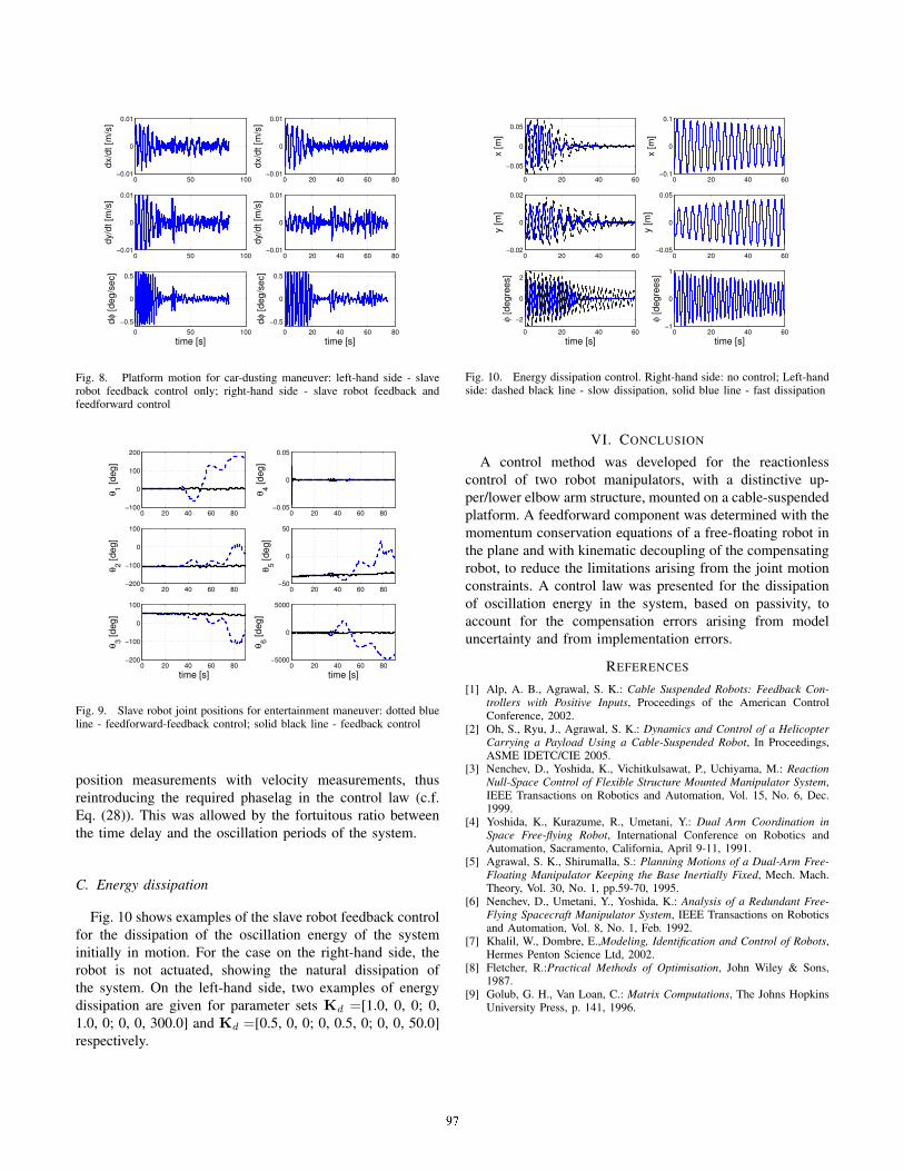
Fig. 8. Platform motion for car-dusting maneuver: left-hand side - slaverobot feedback control only; right-hand side - slave robot feedback andfeedforward control
0 20 40 60 80−100
0
100
200
θ 1 [deg
]
0 20 40 60 80−200
−100
0
100
θ 2 [deg
]
0 20 40 60 80−200
−100
0
100
θ 3 [deg
]
time [s]
0 20 40 60 80−0.05
0
0.05
θ 4 [deg
]
0 20 40 60 80−50
0
50
θ 5 [deg
]
0 20 40 60 80−5000
0
5000
θ 6 [deg
]
time [s]
Fig. 9. Slave robot joint positions for entertainment maneuver: dotted blueline - feedforward-feedback control; solid black line - feedback control
position measurements with velocity measurements, thus
reintroducing the required phaselag in the control law (c.f.
Eq. (28)). This was allowed by the fortuitous ratio between
the time delay and the oscillation periods of the system.
C. Energy dissipation
Fig. 10 shows examples of the slave robot feedback control
for the dissipation of the oscillation energy of the system
initially in motion. For the case on the right-hand side, the
robot is not actuated, showing the natural dissipation of
the system. On the left-hand side, two examples of energy
dissipation are given for parameter sets Kd =[1.0, 0, 0; 0,
1.0, 0; 0, 0, 300.0] and Kd =[0.5, 0, 0; 0, 0.5, 0; 0, 0, 50.0]
respectively.
0 20 40 60
−0.05
0
0.05
x [m
]
0 20 40 60−0.02
0
0.02
y [m
]
0 20 40 60
−2
0
2
φ [d
egre
es]
time [s]
0 20 40 60−0.1
0
0.1
x [m
]
0 20 40 60−0.05
0
0.05
y [m
]
0 20 40 60−1
0
1
φ [d
egre
es]
time [s]
Fig. 10. Energy dissipation control. Right-hand side: no control; Left-handside: dashed black line - slow dissipation, solid blue line - fast dissipation
VI. CONCLUSION
A control method was developed for the reactionless
control of two robot manipulators, with a distinctive up-
per/lower elbow arm structure, mounted on a cable-suspended
platform. A feedforward component was determined with the
momentum conservation equations of a free-floating robot in
the plane and with kinematic decoupling of the compensating
robot, to reduce the limitations arising from the joint motion
constraints. A control law was presented for the dissipation
of oscillation energy in the system, based on passivity, to
account for the compensation errors arising from model
uncertainty and from implementation errors.
REFERENCES
[1] Alp, A. B., Agrawal, S. K.: Cable Suspended Robots: Feedback Con-
trollers with Positive Inputs, Proceedings of the American ControlConference, 2002.
[2] Oh, S., Ryu, J., Agrawal, S. K.: Dynamics and Control of a Helicopter
Carrying a Payload Using a Cable-Suspended Robot, In Proceedings,ASME IDETC/CIE 2005.
[3] Nenchev, D., Yoshida, K., Vichitkulsawat, P., Uchiyama, M.: Reaction
Null-Space Control of Flexible Structure Mounted Manipulator System,IEEE Transactions on Robotics and Automation, Vol. 15, No. 6, Dec.1999.
[4] Yoshida, K., Kurazume, R., Umetani, Y.: Dual Arm Coordination in
Space Free-flying Robot, International Conference on Robotics andAutomation, Sacramento, California, April 9-11, 1991.
[5] Agrawal, S. K., Shirumalla, S.: Planning Motions of a Dual-Arm Free-
Floating Manipulator Keeping the Base Inertially Fixed, Mech. Mach.Theory, Vol. 30, No. 1, pp.59-70, 1995.
[6] Nenchev, D., Umetani, Y., Yoshida, K.: Analysis of a Redundant Free-
Flying Spacecraft Manipulator System, IEEE Transactions on Roboticsand Automation, Vol. 8, No. 1, Feb. 1992.
[7] Khalil, W., Dombre, E.,Modeling, Identification and Control of Robots,Hermes Penton Science Ltd, 2002.
[8] Fletcher, R.:Practical Methods of Optimisation, John Wiley & Sons,1987.
[9] Golub, G. H., Van Loan, C.: Matrix Computations, The Johns HopkinsUniversity Press, p. 141, 1996.