reactive power compensation of wind energy conversion ...ndizdar/inder_paper_wind.pdf · reactive...
TRANSCRIPT

Int. J. Energy Technology and Policy, Vol. 3, No. 3, 2005 269
Reactive power compensation of wind energy conversion system by using Unified Power Flow Controller
Nijaz Dizdarevic* and Matislav Majstrovic Energy Institute Hrvoje Pozar Savska 163, HR-10000 Zagreb, Croatia E-mail: [email protected] E-mail: [email protected] *Corresponding author
Göran Andersson EEH – Power Systems Laboratory ETH-Zentrum, ETL G26, CH-8092 Zürich, Switzerland E-mail: [email protected]
Abstract: Voltage control and reactive power compensation in a distribution network with embedded Wind Energy Conversion System (WECS) represents the main concern of this paper. The WECS is a fixed speed/constant frequency system that is equipped with an induction generator driven by an unregulated wind turbine. The problem is viewed from short-term (10 seconds), mid-term (10 minutes) and long-term (48 hours) time domain responses of the system to different changes of wind speed and load daily cycles. Being disturbed by a variable wind speed, the WECS injects variable active and reactive power into the distribution network exposing nearby consumers to excessive voltage changes. In the FACTS-based solution approach, the Unified Power Flow Controller (UPFC) is used at the point of the WECS network connection to help solve technical issues related to voltage support and series reactive power flow control.
Keywords: Wind Energy Conversion System (WECS); FACTS; UPFC; voltage control; reactive power compensation.
Reference to this paper should be made as follows: Dizdarevic, N., Majstrovic, M. and Andersson, G. (2005) ‘Reactive power compensation of wind energy conversion system by using Unified Power Flow Controller’, Int. J. Energy Technology and Policy, Vol. 3, No. 3, pp.269–298.
Biographical notes: Nijaz Dizdarevic received his BSc, MSc, and PhD degrees from the University of Zagreb, Croatia in 1990, 1994, and 2001, respectively. From 1991 to 2001 he was with the Department of Power Systems at the same university. During 1996 and 1997 he was at the Royal Institute of Technology in Stockholm, Sweden. Since 2002 he has been with the Energy Institute Hrvoje Pozar in Zagreb, working on power system control and stability.
Matislav Majstrovic received his BSc, MSc, and PhD degrees from the University of Split and University of Zagreb, Croatia in 1973, 1979, and 1986, respectively. He is currently Senior Researcher at the Energy Institute Hrvoje Pozar in Zagreb and a full professor at the University of Split – Faculty of Electrical Engineering. His interests are in the area of electricity transmission and distribution network analysis.
Copyright © 2005 Inderscience Enterprises Ltd.

270 N. Dizdarevic, M. Majstrovic and G. Andersson
Göran Andersson (M’86, SM’91, F’97) received his CivIng and PhD degrees from the Lund Institute of Technology, Sweden in 1975 and 1980, respectively. From 1986 to 2000 he was Professor at the Royal Institute of Technology in Stockholm, Sweden. Since 2000 he has been a full Professor at the ETH in Zurich, Switzerland. He is a member of the Royal Swedish Academy of Engineering Sciences and the Royal Swedish Academy of Sciences.
1 Introduction
Alternative solutions treating distributed generation of electrical energy have recently appeared as a consequence of strong ecological concerns with regard to almost all major industrial branches, as shown by Jenkins et al. (2000), CIGRÉ (1999) and Ackermann et al. (2001). Moreover, initiatives of potential investors have come along with the liberalisation of the electrical energy market. According to Hatziargyriou (2002) and Lopes (2002), this has an additional impact on the need for conducting a new kind of technical analysis. Heier (1998) and CIGRÉ (2000a) pointed out that grid integration aspects of renewable sources have become increasingly important as incentives come in large numbers. From the distribution network viewpoint, the connection of small power plants with dispersed generation of electricity calls for urgent attention. In case of increased power ratings, dispersed power plants could be integrated in a transmission network.
The dispersed generation of electricity is often a subject of polarised discussions. At one side, experienced engineers motivated by a wide knowledge of complex power systems operations are concerned regarding the fundamental realisation of the massive introduction of unregulated and uncontrollable generators into the distribution network. At the other side, enthusiastic proponents of renewable sources believe that such generating units are a necessity in operation should domestic and international requirements for the reduction of CO2 emission be fulfilled. Moreover, they are convinced that renewables decrease dependence on dominant energy fuels (gas, oil, coal…) in times of a large international crisis.
The increased penetration of renewables such as wind energy creates an uncontrollable component in the electric power system. Based on weather forecasts it is possible to predict the mean wind speed in a short-term time period, but not the dynamic changes, smaller or larger, which take place around the base speed. Dynamic changes of wind speed make the amount of power injected into the network highly variable. Depending on the intensity and the rate of changes, difficulties with the frequency and voltage regulation could appear to make a direct impact on the quality level of delivered electrical energy. Conditions of economic justification set the project requirements for wind power plant installations in areas with a high wind utilisation. Such areas are often located in rural zones with relatively weak electrical networks. In order to establish a balance between the polarised attitudes, it is necessary to provide answers concerning technical, economic, and security aspects related to the grid integration of wind energy conversion systems.
Reactive power compensation of wind energy conversion system 271
From that viewpoint, the objective of this paper is to create a countermeasure aimed
at suppressing excessive voltage changes to nearby consumers and to minimise reactive power exchange between the wind energy conversion system and the distribution network. Without a countermeasure, it is possible that at some locations only a small number of windturbines could be connected due to weak voltage conditions and increased losses in the nearby network. That would not only leave assessed wind potential unused, but it could also prohibit installation of a larger number of wind turbines jeopardising the economics of the whole project.
In attempt to overcome negative dynamic impacts caused by wind speed changes, the voltage regulation and reactive power compensation problem is approached here not only from the conventional aspect, but from a FACTS-based one as well. The induction generator of wind energy conversion systems is viewed as the consumer of reactive power. Its reactive power consumption depends on active power production. Conventionally, shunt capacitor banks are connected to the generator terminals to compensate its reactive power consumption. In some schemes, shunt capacitor banks could automatically be switched on/off by using a feedback signal from the generator reactive power. The capacitor switching is triggered through algorithm if the generator reactive power is outside the allowed dead-band for a specified time period.
Further on, continuous voltage control and reactive power compensation at the point of the WECS network connection is provided by using a FACTS-based device. Among FACTS devices, the Unified Power Flow Controller (UPFC) is chosen due to its versatile regulating capabilities, illustrated by Dizdarevic (2001). The UPFC consists of shunt and series branches, which could be interchangeably used. Being located at the point of the WECS connection to the distribution network, it is made possible to simultaneously control the WECS bus voltage magnitude and/or series reactive power flow that the WECS exchanges with the network. This countermeasure is expected to contribute to making assessed wind site viable for connecting a larger number of windturbines.
2 System modelling
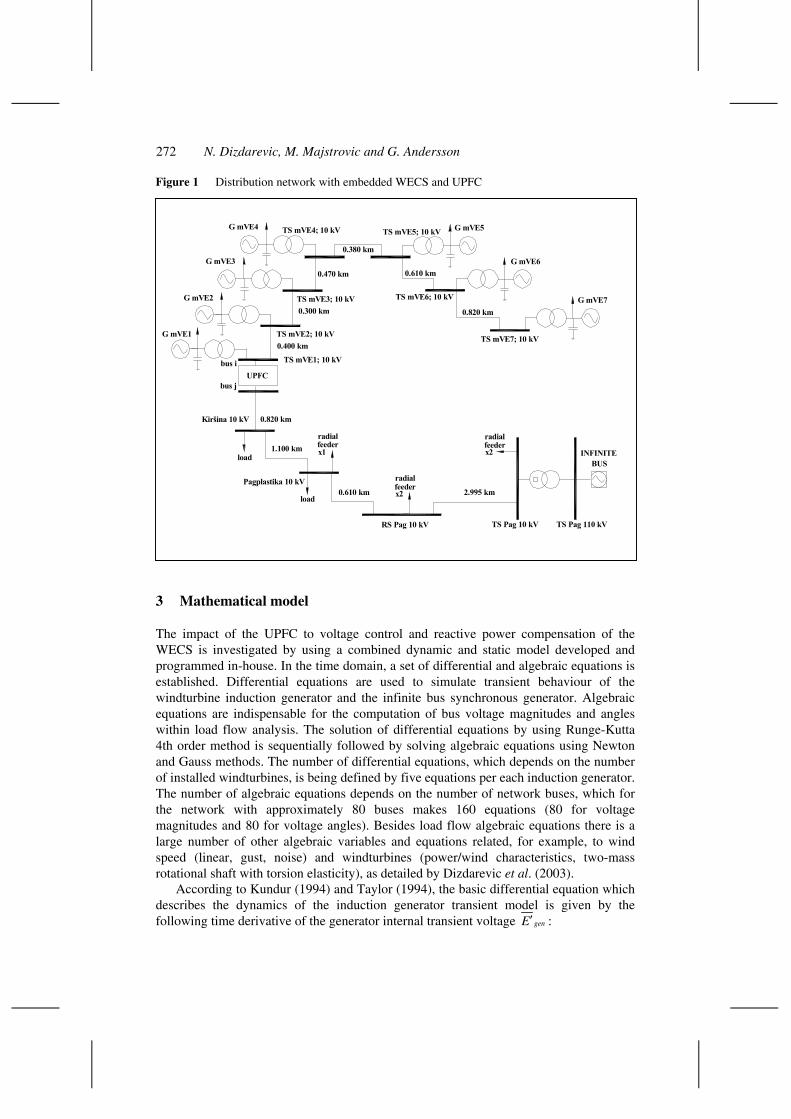
The improvement of voltage control and reactive power compensation by using the UPFC at the point of connection of the small-sized WECS (7 × 800 kW) is set here as the main objective. The WECS is connected to the 10 kV distribution network (78 buses, 77 branches) with no other generating units present except the one at the main in-feed point representing a slack bus at 110 kV (Figure 1). It is supposed that the WECS is of a fixed speed/constant frequency type, equipped with an induction generator driven by an unregulated wind turbine. If such system, detailed by Dizdarevic et al. (2003), is connected to a weak network, some fast and large changes around the mean wind speed may cause excessive voltage changes to nearby consumers due to fluctuations in injected power by the WECS. The UPFC is located at the WECS connection point to the distribution network. The distribution network is connected through an LTC transformer to a 110 kV transmission network. Basic parameters of the system are given in the Appendix.
272 N. Dizdarevic, M. Majstrovic and G. Andersson
Figure 1 Distribution network with embedded WECS and UPFC
TS Pag 10 kV TS Pag 110 kVRS Pag 10 kV
Pagplastika 10 kV
Kiršina 10 kV
INFINITE
TS mVE1; 10 kV
TS mVE2; 10 kV
TS mVE3; 10 kV
TS mVE4; 10 kV TS mVE5; 10 kV
TS mVE6; 10 kV
TS mVE7; 10 kVG mVE1
G mVE2
G mVE3
G mVE4 G mVE5
G mVE6
G mVE7
load
load
feederx2
radial
x2feederradial
radialfeederx1
2.995 km0.610 km
1.100 km
0.820 km
0.400 km
0.300 km
0.470 km
0.380 km
0.610 km
0.820 km
BUS
UPFCbus i
bus j
3 Mathematical model
The impact of the UPFC to voltage control and reactive power compensation of the WECS is investigated by using a combined dynamic and static model developed and programmed in-house. In the time domain, a set of differential and algebraic equations is established. Differential equations are used to simulate transient behaviour of the windturbine induction generator and the infinite bus synchronous generator. Algebraic equations are indispensable for the computation of bus voltage magnitudes and angles within load flow analysis. The solution of differential equations by using Runge-Kutta 4th order method is sequentially followed by solving algebraic equations using Newton and Gauss methods. The number of differential equations, which depends on the number of installed windturbines, is being defined by five equations per each induction generator. The number of algebraic equations depends on the number of network buses, which for the network with approximately 80 buses makes 160 equations (80 for voltage magnitudes and 80 for voltage angles). Besides load flow algebraic equations there is a large number of other algebraic variables and equations related, for example, to wind speed (linear, gust, noise) and windturbines (power/wind characteristics, two-mass rotational shaft with torsion elasticity), as detailed by Dizdarevic et al. (2003).
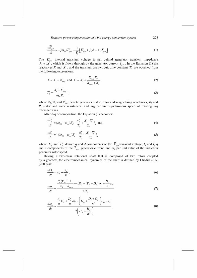
According to Kundur (1994) and Taylor (1994), the basic differential equation which describes the dynamics of the induction generator transient model is given by the following time derivative of the generator internal transient voltage genE′ :
Reactive power compensation of wind energy conversion system 273
00
1( )gen
s gen gen gen
dEj sE E j X X I
dt Tω
′′ ′ ′= − − + −′
(1)
The genE′ internal transient voltage is put behind generator transient impedance
SR jX ′+ , which is flown through by the generator current genI . In the Equation (1) the reactances X and , and the transient open-circuit time constant TX ′
0′ are obtained from
the following expressions:
s mX X X= + ag and mag rS
mag r
X XX X
X X′ = +
+ (2)
00
r ma
s r
X XT
Rω+
′ = g , (3)
where XS, Xr and Xmag denote generator stator, rotor and magnetising reactances, RS and Rr stator and rotor resistances, and ω0S per unit synchronous speed of rotating d-q reference axes.
After d-q decomposition, the Equation (1) becomes:
00 0
( )q qS m d
dE E X XdE I
dt T Tω ω
′ ′ ′−′= − − + and (4)
00 0
( )d dS m q
dE E X XqE I
dt T Tω ω
′ ′ ′−′= − − − −′
, (5)
where qE′ and dE′ denote q and d components of the genE′ transient voltage, Iq and Id q and d components of the genI generator current, and ωm per unit value of the induction generator rotor speed.
Having a two-mass rotational shaft that is composed of two rotors coupled by a gearbox, the electromechanical dynamics of the shaft is defined by Chedid et al. (2000) as:
cT
d
dt nmω
ωΘ
= − , (6)
( ) 1( )
2
w w cc c c T T m
T ngenT
T
P V Dc D D
S nd
dt H
ω ωωω
− Θ − + +
= (7)
2
22
c gc cc T m m
m
gm
D Dc DeD T
n n nd
HdtH
n
ω ωω
+ Θ + − + −
=
+
, (8)

274 N. Dizdarevic, M. Majstrovic and G. Andersson
where:
Θc shaft torsion angle between windturbine and induction generator rotor (rade) ωT, ωm windturbine and induction generator rotor speeds (per unit values, in steady
state ωT = ωm/n) 1:n transmission gear ratio between the two speeds Pw aerodynamic power (W) Vw wind speed (m/s)
Sngen rated apparent power of induction generator (VA) cc torsion stiffness coefficient (pu/rade)
Dc torsion damping coefficient (pu/pu) DT damping coefficient of windturbine (pu/pu) Dg damping coefficient of gear-box (pu/pu) Dm damping coefficient of induction generator (pu/pu) HT inertia constant of windturbine (s) Hg inertia constant of gearbox (s) Hm inertia constant of induction generator (s).
The electromagnetic torque Te is computed as it follows:
0
( )d d q qe
S
E I E IT
ω
′ ′+= (9)
Besides noted differential equations, the induction generator transient model also comprises these four algebraic equations:
2 2( )q S d S d S d qX E R E R X I R V X V′ ′ ′ ′ ′− + − + − + = 0
0
N
t
T≤ ≤ +
, (10)
2 2( )S q d S q d S qR E X E R X I X V R V′ ′ ′ ′ ′+ − + − − = , (11)
sin 0d n nV V− Θ = (12)
cos 0q n nV V− Θ = . (13)
Anderson (1983) proposed that the numerical analysis of the dynamics induced by the wind speed changes should be conducted by using the four-term composite expression:
w wB wR wG wV V V V V= + + + (14)
where VwB represents a base component, VwR linear (ramp) component, VwG gust component and VwN noise component.
Base component VwB of the wind speed Vw is defined as:
.wBV cons= (15)
Linear component VwR of the wind speed Vw is defined as:
1
1 1
1
0
*
R
wR ramp R R R
wB R R
for t T
V V for T t T
MAXR V for t T T
<
= > +
, (16)
Reactive power compensation of wind energy conversion system 275
where Vramp should be computed from:
1* Rramp wB
R
t TV MAXR V
T
−= . (17)
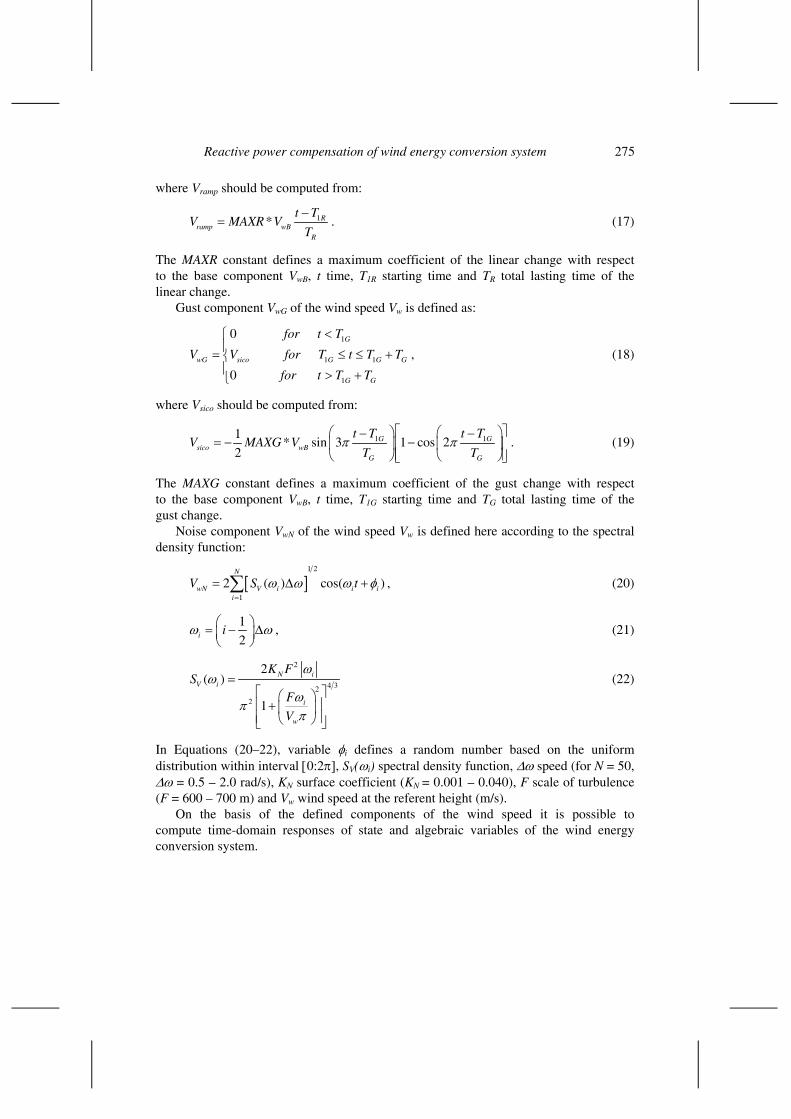
The MAXR constant defines a maximum coefficient of the linear change with respect to the base component VwB, t time, T1R starting time and TR total lasting time of the linear change.
Gust component VwG of the wind speed Vw is defined as:
1
1 1
1
0
0
G
wG sico G G G
G G
for t T
V V for T t T
for t T T
<= ≤ > +
T≤ + , (18)
where Vsico should be computed from:
11* sin 3 1 cos 2
2G
sico wBG G
t T t TV MAXG V
T Tπ π 1G
− −= − −
. (19)
The MAXG constant defines a maximum coefficient of the gust change with respect to the base component VwB, t time, T1G starting time and TG total lasting time of the gust change.
Noise component VwN of the wind speed Vw is defined here according to the spectral density function:
[ ]1 2
1
2 ( ) cos(N
wN V i i ii
V S t )ω ω ω=
= ∆∑ φ+ , (20)
1
2i iω ω = − ∆
, (21)
2
4 32
2
2( )
1
N iV i
i
w
K FS
F
V
ωω
ωπ
π
= +
(22)
In Equations (20–22), variable φi defines a random number based on the uniform distribution within interval [0:2π], SV(ωi) spectral density function, ∆ω speed (for N = 50, ∆ω = 0.5 – 2.0 rad/s), KN surface coefficient (KN = 0.001 – 0.040), F scale of turbulence (F = 600 – 700 m) and Vw wind speed at the referent height (m/s).
On the basis of the defined components of the wind speed it is possible to compute time-domain responses of state and algebraic variables of the wind energy conversion system.
276 N. Dizdarevic, M. Majstrovic and G. Andersson
4 Reactive power compensation of the WECS
Shunt capacitor banks are treated here as conventional means of discrete reactive power compensation. They are compared to the UPFC which, for the sake of this illustration, provides continuous voltage control and reactive power compensation simultaneously. Shunt capacitor banks are located at the induction generator terminals to compensate its reactive power consumption, whereas the UPFC is located at the point of the WECS network connection.
The UPFC can provide simultaneous control of all basic power system parameters (voltage, impedance and phase angle) and dynamic system compensation, as shown by Gyugyi (1995) and CIGRÉ (2000b). The controller can fulfil functions of reactive shunt compensation, series compensation and phase shifting meeting multiple control objectives.
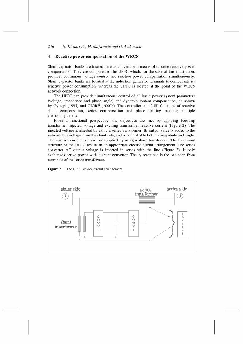
From a functional perspective, the objectives are met by applying boosting transformer injected voltage and exciting transformer reactive current (Figure 2). The injected voltage is inserted by using a series transformer. Its output value is added to the network bus voltage from the shunt side, and is controllable both in magnitude and angle. The reactive current is drawn or supplied by using a shunt transformer. The functional structure of the UPFC results in an appropriate electric circuit arrangement. The series converter AC output voltage is injected in series with the line (Figure 3). It only exchanges active power with a shunt converter. The xS reactance is the one seen from terminals of the series transformer.
Figure 2 The UPFC device circuit arrangement
Reactive power compensation of wind energy conversion system 277
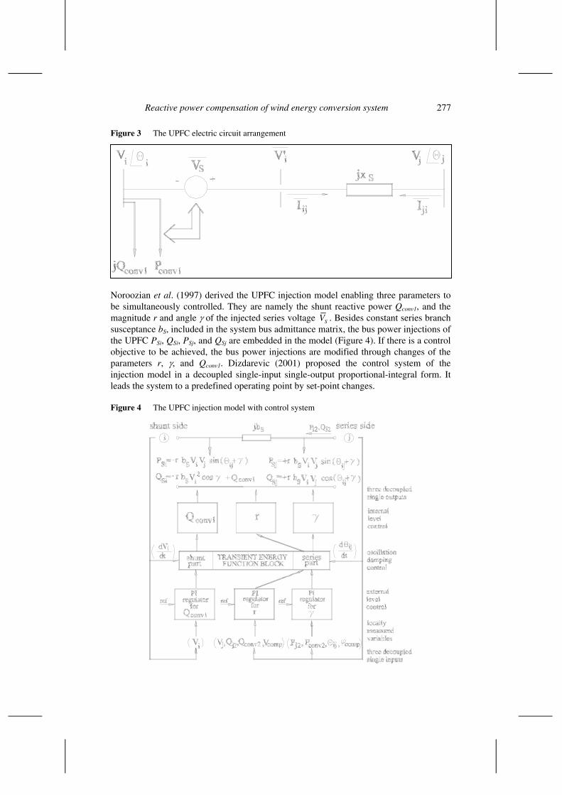
Figure 3 The UPFC electric circuit arrangement
Noroozian et al. (1997) derived the UPFC injection model enabling three parameters to be simultaneously controlled. They are namely the shunt reactive power Qconv1, and the magnitude r and angle γ of the injected series voltage SV . Besides constant series branch susceptance bS, included in the system bus admittance matrix, the bus power injections of the UPFC PSi, QSi, PSj, and QSj are embedded in the model (Figure 4). If there is a control objective to be achieved, the bus power injections are modified through changes of the parameters r, γ, and Qconv1. Dizdarevic (2001) proposed the control system of the injection model in a decoupled single-input single-output proportional-integral form. It leads the system to a predefined operating point by set-point changes.
Figure 4 The UPFC injection model with control system

278 N. Dizdarevic, M. Majstrovic and G. Andersson
The selection of input/output signals depends on the predetermined control mode. At the external level, the following locally measured variables of the UPFC are controlled:
• by changing Qconv1
a shunt side bus voltage magnitude, Vi
• by changing r
a series side bus voltage magnitude, Vj
b reactive power flow into series side bus, Qj2
c reactive power requirement of the series side converter CONV2, Qconv2
d compensating voltage magnitude, Vcomp.
• by changing γ
a active power flow into the series side bus, Pj2
b active power requirement of the series side converter CONV2, Pconv2
c bus voltage angle difference, Θij
d compensating voltage angle, ϕcomp.
In the model, as shown by Dizdarevic et al. (1999), the shunt side could be controlled only in the voltage mode, Vi ↔ Qconv1, emphasising that the Qconv1 parameter represents the reactive power loading of the shunt converter. The series side could be controlled through the r ⇔ γ pair in the following modes:
• bus voltage magnitude and active power flow, Vj ⇔ Pj2
• reactive and active power flows, Qj2 ⇔ Pj2
• series compensation, Qconv2 ⇔ Pconv2(= 0)
• phase shifting of Phase Angle Regulator (PAR) type, Vj (= Vi) ⇔ Θij
• phase shifting of Quadrature Booster Transformer (QBT) type, Vcomp ⇔ ϕcomp(= π/2).
The variables are chosen to satisfy general V ↔ Q and Θ ↔ P decoupling. Therefore, the control system enables the UPFC injection model to participate in several different modes of operation fully utilising its versatile regulating capabilities. Additional differential equations are defined for the control system of the UPFC injection model described by proportional-integration characteristics. The UPFC injection model is included in the overall system model. The control system of the injection model is proposed and the benefits within the WECS voltage/reactive power problem are explored.
5 Numerical results
Conventional and FACTS-based devices are applied in order to flatten voltage profile, preserve stability, correct power factor, and decrease power and energy losses by minimising the reactive power flow in the network. Within the scope of the voltage control and reactive power compensation problem, power conditions are analysed as a
Reactive power compensation of wind energy conversion system 279
part of the whole problem related to technical aspects of grid integration of the WECS. The FACTS-based device is situated at the point of connection of the small-sized WECS (7 × 800 kW) to the reinforced network configuration. The WECS is of a fixed speed/constant frequency type equipped with an induction generator that is driven by an unregulated wind turbine. Power conditions at the network buses are dynamically analysed as functions of the previously defined wind speed changes. Conditions of increased interaction between the WECS and the LTC transformer are predicted in times of extremely turbulent winds. The transfer of the WECS from the infinite-bus operating mode to the isolated one is also analysed.
5.1 Linear change of the wind speed
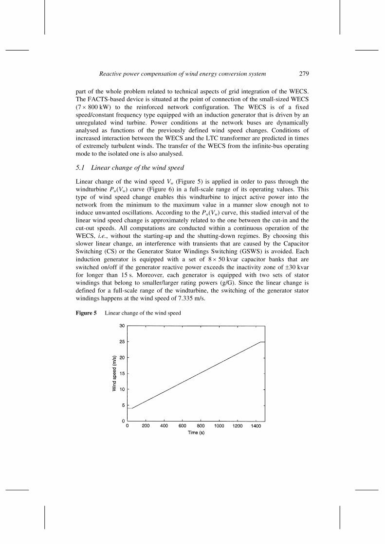
Linear change of the wind speed Vw (Figure 5) is applied in order to pass through the windturbine Pw(Vw) curve (Figure 6) in a full-scale range of its operating values. This type of wind speed change enables this windturbine to inject active power into the network from the minimum to the maximum value in a manner slow enough not to induce unwanted oscillations. According to the Pw(Vw) curve, this studied interval of the linear wind speed change is approximately related to the one between the cut-in and the cut-out speeds. All computations are conducted within a continuous operation of the WECS, i.e., without the starting-up and the shutting-down regimes. By choosing this slower linear change, an interference with transients that are caused by the Capacitor Switching (CS) or the Generator Stator Windings Switching (GSWS) is avoided. Each induction generator is equipped with a set of 8 × 50 kvar capacitor banks that are switched on/off if the generator reactive power exceeds the inactivity zone of ±30 kvar for longer than 15 s. Moreover, each generator is equipped with two sets of stator windings that belong to smaller/larger rating powers (g/G). Since the linear change is defined for a full-scale range of the windturbine, the switching of the generator stator windings happens at the wind speed of 7.335 m/s.
Figure 5 Linear change of the wind speed
280 N. Dizdarevic, M. Majstrovic and G. Andersson
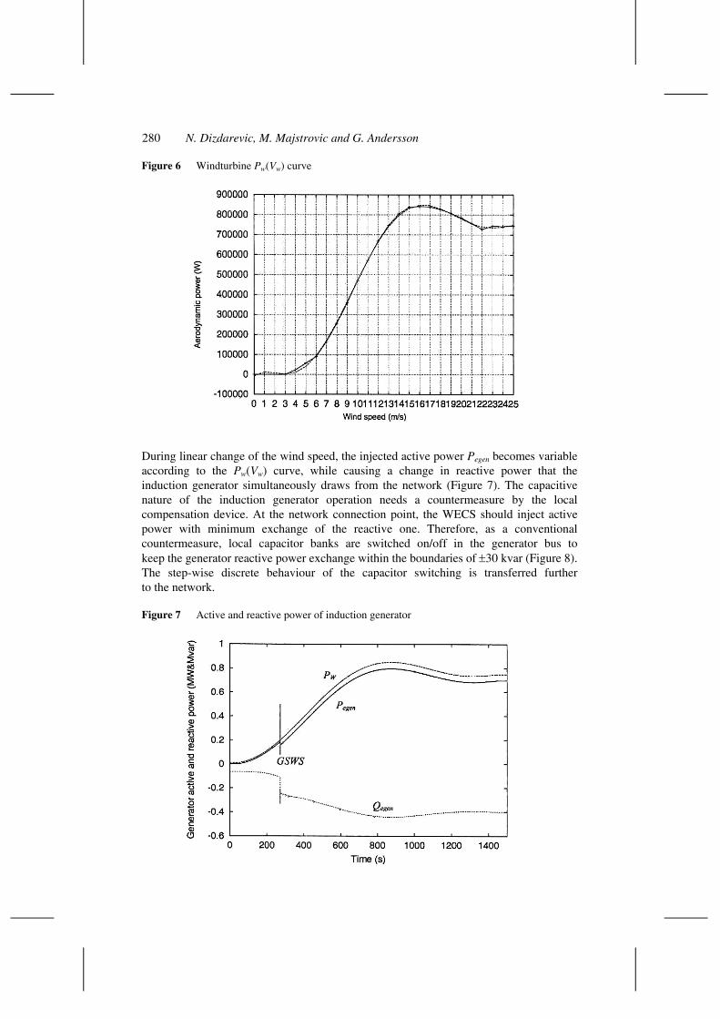
Figure 6 Windturbine Pw(Vw) curve
During linear change of the wind speed, the injected active power Pegen becomes variable according to the Pw(Vw) curve, while causing a change in reactive power that the induction generator simultaneously draws from the network (Figure 7). The capacitive nature of the induction generator operation needs a countermeasure by the local compensation device. At the network connection point, the WECS should inject active power with minimum exchange of the reactive one. Therefore, as a conventional countermeasure, local capacitor banks are switched on/off in the generator bus to keep the generator reactive power exchange within the boundaries of ±30 kvar (Figure 8). The step-wise discrete behaviour of the capacitor switching is transferred further to the network.
Figure 7 Active and reactive power of induction generator

Reactive power compensation of wind energy conversion system 281
Figure 8 Reactive power flow in generator buses (GEN1 and GEN7)
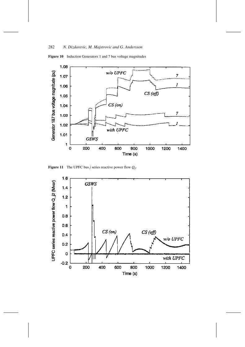
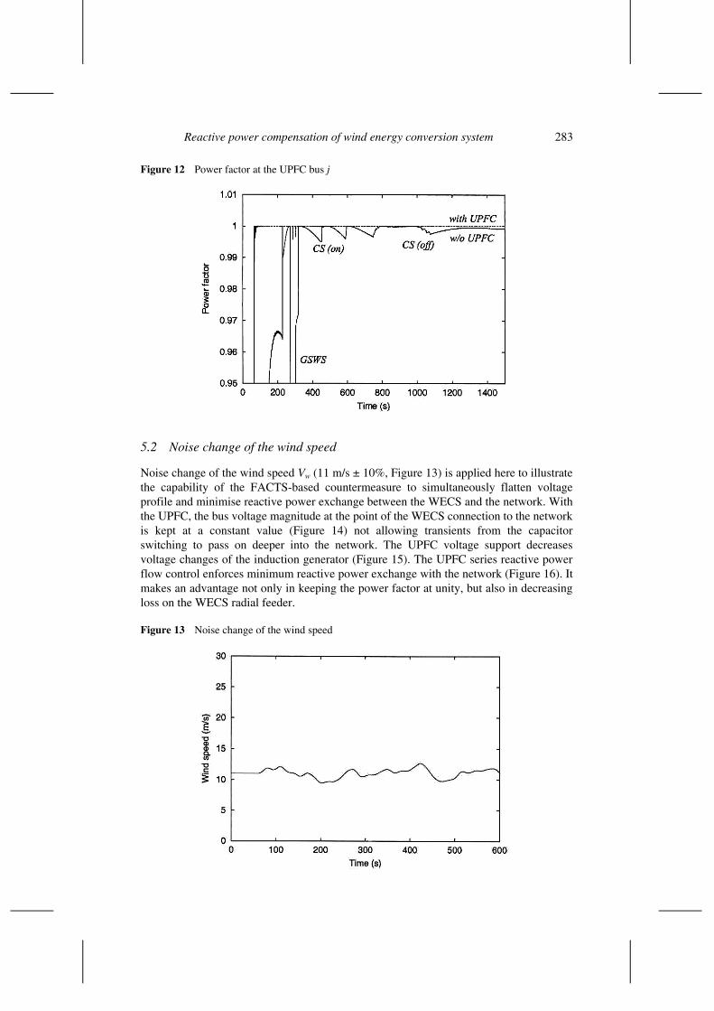
Such a FACTS-based countermeasure is capable of neutralising the discrete behaviour of the conventional one by enforcing a continuous response of the WECS voltage and reactive power to the wind speed change at the point of the network connection. If the UPFC serves as a coupler between the WECS and the network, it is possible to simultaneously control bus voltage magnitude (Figure 9) which indirectly decreases generator voltage changes (Figure 10), and to annul the series reactive power flow (Figure 11) which indirectly keeps the power factor precisely at unity (Figure 12).
Figure 9 The UPFC bus i voltage magnitude Vi
282 N. Dizdarevic, M. Majstrovic and G. Andersson
Figure 10 Induction Generators 1 and 7 bus voltage magnitudes
Figure 11 The UPFC bus j series reactive power flow Qj2
Reactive power compensation of wind energy conversion system 283
Figure 12 Power factor at the UPFC bus j
5.2 Noise change of the wind speed
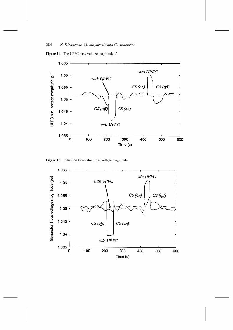
Noise change of the wind speed Vw (11 m/s ± 10%, Figure 13) is applied here to illustrate the capability of the FACTS-based countermeasure to simultaneously flatten voltage profile and minimise reactive power exchange between the WECS and the network. With the UPFC, the bus voltage magnitude at the point of the WECS connection to the network is kept at a constant value (Figure 14) not allowing transients from the capacitor switching to pass on deeper into the network. The UPFC voltage support decreases voltage changes of the induction generator (Figure 15). The UPFC series reactive power flow control enforces minimum reactive power exchange with the network (Figure 16). It makes an advantage not only in keeping the power factor at unity, but also in decreasing loss on the WECS radial feeder.
Figure 13 Noise change of the wind speed
284 N. Dizdarevic, M. Majstrovic and G. Andersson
Figure 14 The UPFC bus i voltage magnitude Vi
Figure 15 Induction Generator 1 bus voltage magnitude

Reactive power compensation of wind energy conversion system 285
Figure 16 The UPFC bus j series reactive power flow Qj2
5.3 Gust change of the wind speed
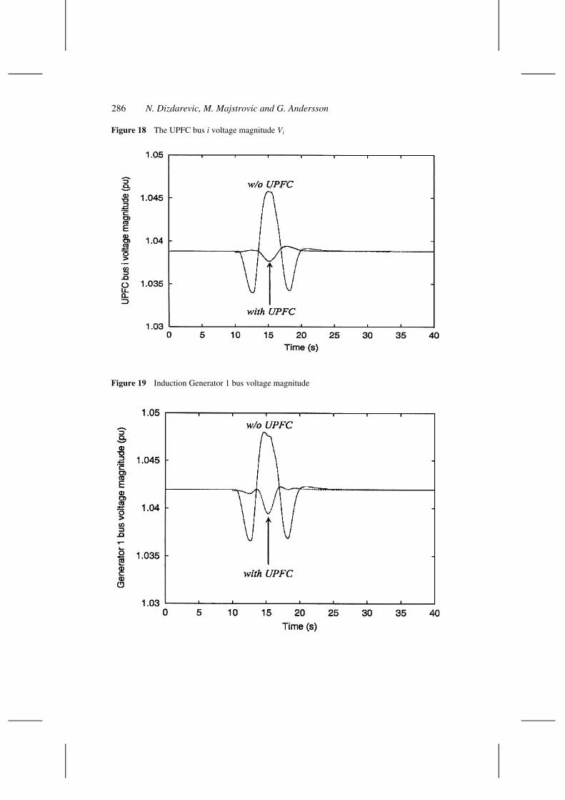
Gust change of the wind speed Vw (Figure 17) also emphasises the unique capability of the FACTS-based countermeasure to prevent the WECS voltage and reactive power from fast fluctuations induced by fast wind speed changes. The gust change is defined as periods of 10.5 s with 40% maximum deviation from the initial value of the wind speed equal to 8.5 m/s. With the UPFC, the bus voltage magnitude at the point of the WECS connection to the network exhibits much smaller changes than in the case without the UPFC (Figure 18). The UPFC voltage support decreases voltage changes of the induction generator as well (Figure 19). Due to the time delay of 15 s in the capacitor switching criterion, this gust change does not initiate any of them. Simultaneously, control of the UPFC series reactive power flow significantly decreases reactive power exchange with the network (Figure 20).
Figure 17 Gust change of the wind speed
286 N. Dizdarevic, M. Majstrovic and G. Andersson
Figure 18 The UPFC bus i voltage magnitude Vi
Figure 19 Induction Generator 1 bus voltage magnitude
Reactive power compensation of wind energy conversion system 287
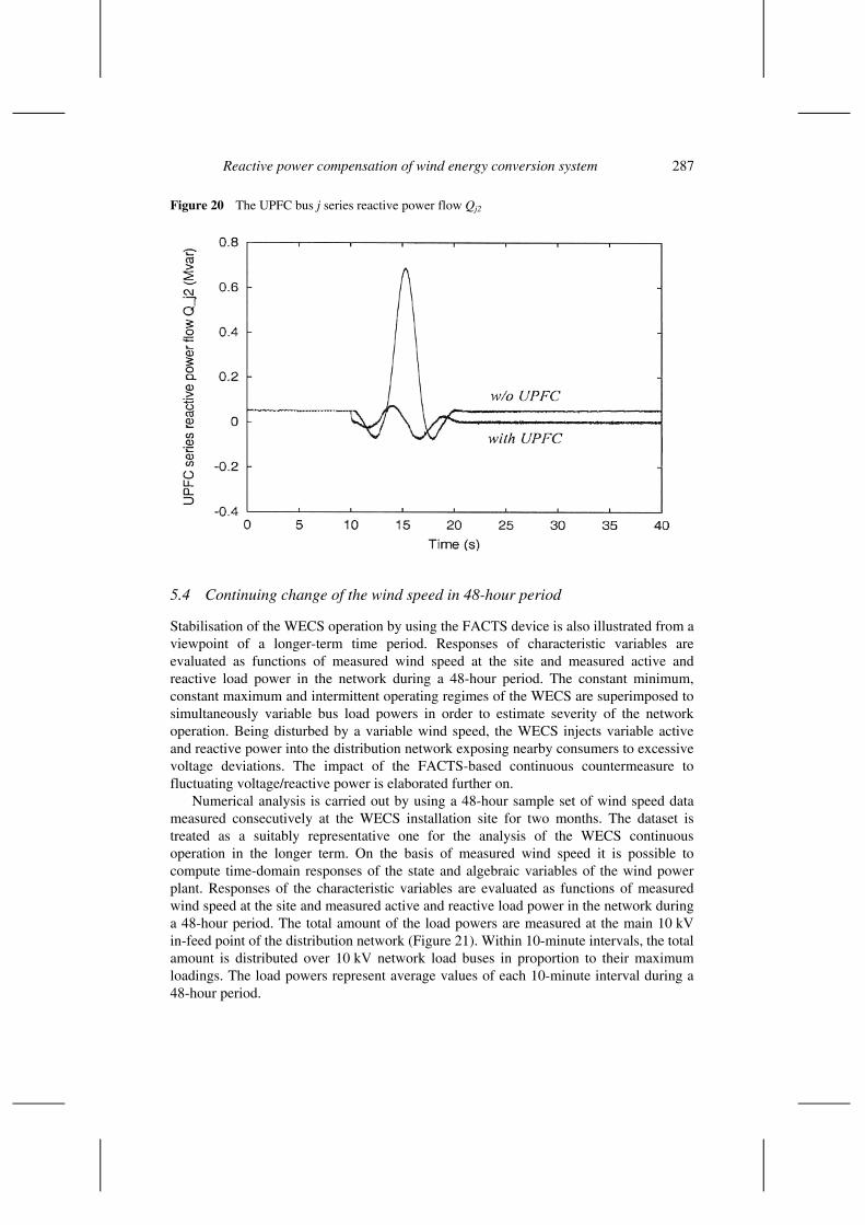
Figure 20 The UPFC bus j series reactive power flow Qj2
5.4 Continuing change of the wind speed in 48-hour period
Stabilisation of the WECS operation by using the FACTS device is also illustrated from a viewpoint of a longer-term time period. Responses of characteristic variables are evaluated as functions of measured wind speed at the site and measured active and reactive load power in the network during a 48-hour period. The constant minimum, constant maximum and intermittent operating regimes of the WECS are superimposed to simultaneously variable bus load powers in order to estimate severity of the network operation. Being disturbed by a variable wind speed, the WECS injects variable active and reactive power into the distribution network exposing nearby consumers to excessive voltage deviations. The impact of the FACTS-based continuous countermeasure to fluctuating voltage/reactive power is elaborated further on.
Numerical analysis is carried out by using a 48-hour sample set of wind speed data measured consecutively at the WECS installation site for two months. The dataset is treated as a suitably representative one for the analysis of the WECS continuous operation in the longer term. On the basis of measured wind speed it is possible to compute time-domain responses of the state and algebraic variables of the wind power plant. Responses of the characteristic variables are evaluated as functions of measured wind speed at the site and measured active and reactive load power in the network during a 48-hour period. The total amount of the load powers are measured at the main 10 kV in-feed point of the distribution network (Figure 21). Within 10-minute intervals, the total amount is distributed over 10 kV network load buses in proportion to their maximum loadings. The load powers represent average values of each 10-minute interval during a 48-hour period.
288 N. Dizdarevic, M. Majstrovic and G. Andersson
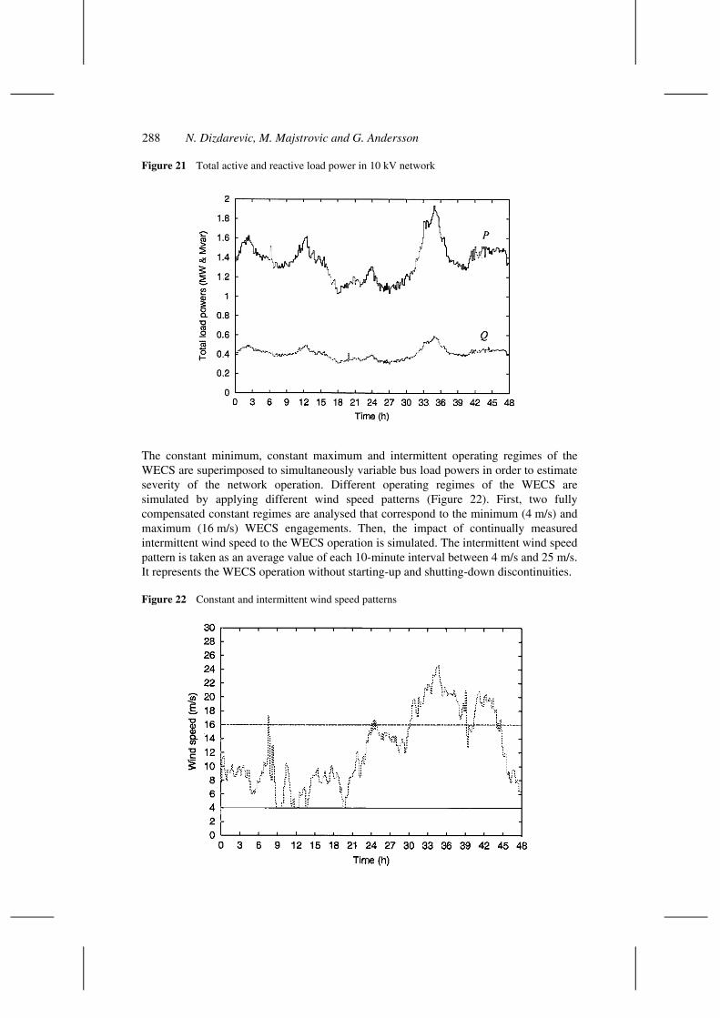
Figure 21 Total active and reactive load power in 10 kV network
The constant minimum, constant maximum and intermittent operating regimes of the WECS are superimposed to simultaneously variable bus load powers in order to estimate severity of the network operation. Different operating regimes of the WECS are simulated by applying different wind speed patterns (Figure 22). First, two fully compensated constant regimes are analysed that correspond to the minimum (4 m/s) and maximum (16 m/s) WECS engagements. Then, the impact of continually measured intermittent wind speed to the WECS operation is simulated. The intermittent wind speed pattern is taken as an average value of each 10-minute interval between 4 m/s and 25 m/s. It represents the WECS operation without starting-up and shutting-down discontinuities.
Figure 22 Constant and intermittent wind speed patterns
Reactive power compensation of wind energy conversion system 289
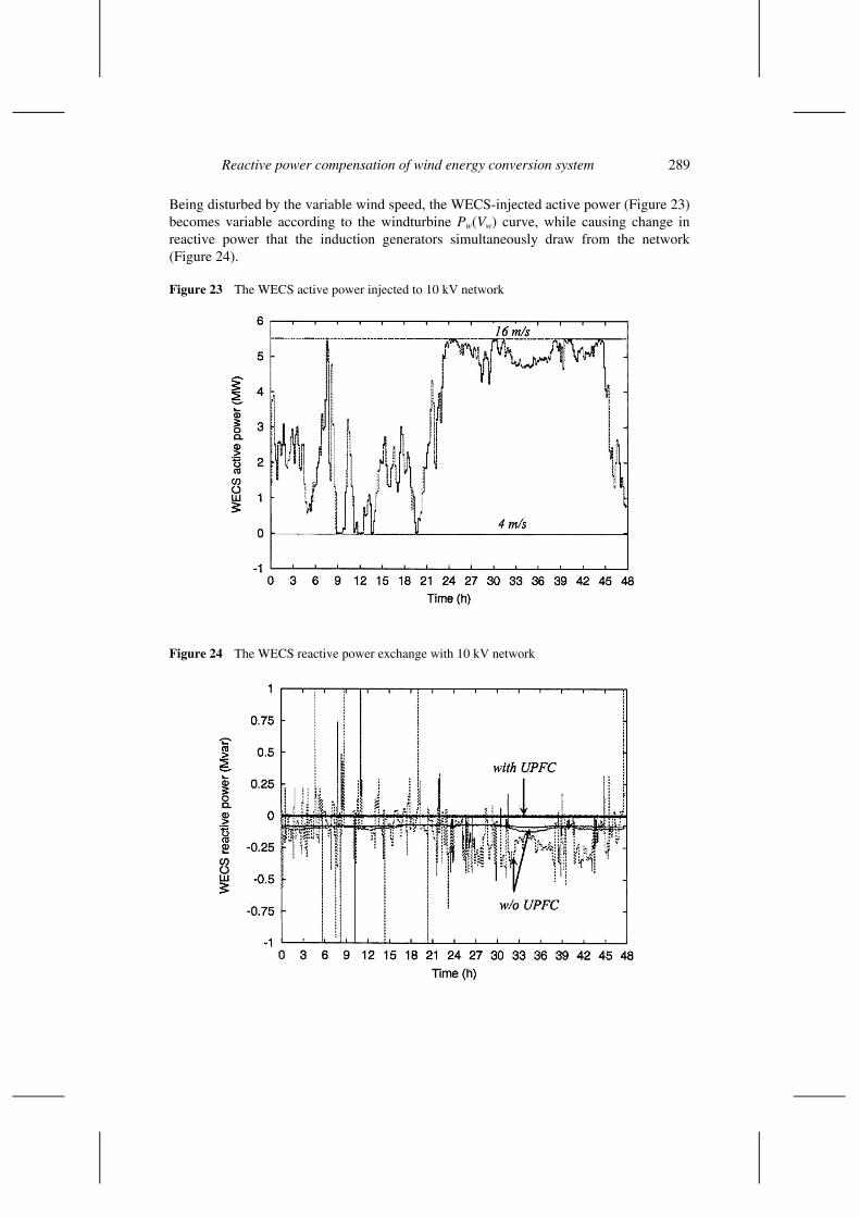
Being disturbed by the variable wind speed, the WECS-injected active power (Figure 23) becomes variable according to the windturbine Pw(Vw) curve, while causing change in reactive power that the induction generators simultaneously draw from the network (Figure 24).
Figure 23 The WECS active power injected to 10 kV network
Figure 24 The WECS reactive power exchange with 10 kV network
290 N. Dizdarevic, M. Majstrovic and G. Andersson
At the network connection point, the WECS should inject active power with minimum exchange of the reactive one. It is seen that not only the conventional countermeasure has a step-wise discrete behaviour, but its switching sequences are transferred further to the network. If the UPFC is activated in the voltage/reactive power mode, the impact to the WECS active power is negligible. But, its impact to the WECS reactive power is significant. In the case of intermittent wind speed pattern without the UPFC’s support (dotted curve in Figure 24), the WECS reactive power exchange with the 10 kV network exhibits serious deviations in comparison to the non-intermittent ones (4 m/s and 16 m/s).
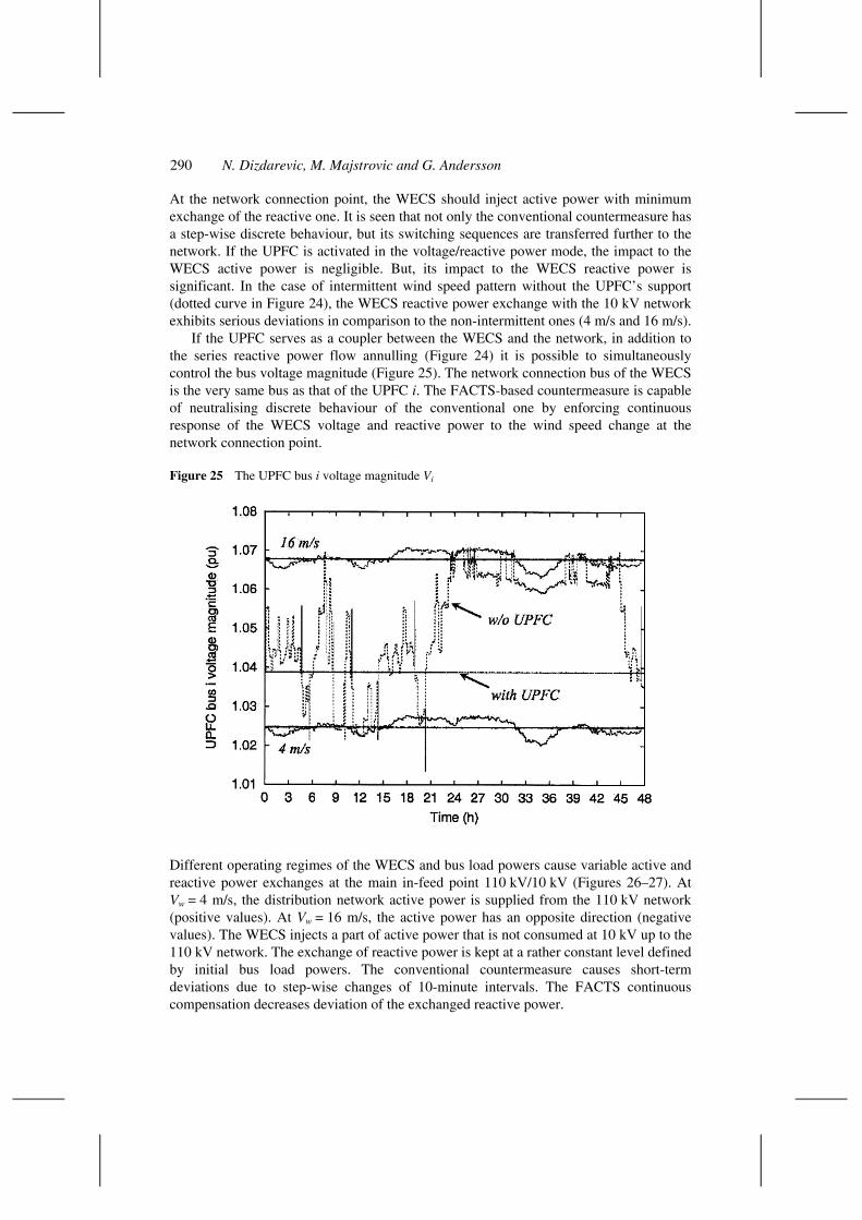
If the UPFC serves as a coupler between the WECS and the network, in addition to the series reactive power flow annulling (Figure 24) it is possible to simultaneously control the bus voltage magnitude (Figure 25). The network connection bus of the WECS is the very same bus as that of the UPFC i. The FACTS-based countermeasure is capable of neutralising discrete behaviour of the conventional one by enforcing continuous response of the WECS voltage and reactive power to the wind speed change at the network connection point.
Figure 25 The UPFC bus i voltage magnitude Vi
Different operating regimes of the WECS and bus load powers cause variable active and reactive power exchanges at the main in-feed point 110 kV/10 kV (Figures 26–27). At Vw = 4 m/s, the distribution network active power is supplied from the 110 kV network (positive values). At Vw = 16 m/s, the active power has an opposite direction (negative values). The WECS injects a part of active power that is not consumed at 10 kV up to the 110 kV network. The exchange of reactive power is kept at a rather constant level defined by initial bus load powers. The conventional countermeasure causes short-term deviations due to step-wise changes of 10-minute intervals. The FACTS continuous compensation decreases deviation of the exchanged reactive power.

Reactive power compensation of wind energy conversion system 291
Figure 26 Active power exchange at in-feed point 110 kV/10 kV
Figure 27 Reactive power exchange at in-feed point 110 kV/10 kV
292 N. Dizdarevic, M. Majstrovic and G. Andersson
5.5 Interaction between the WECS and the LTC transformer
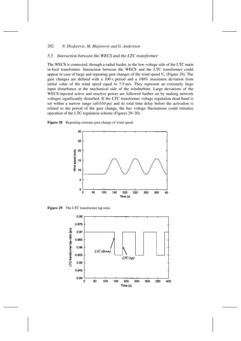
The WECS is connected, through a radial feeder, to the low-voltage side of the LTC main in-feed transformer. Interaction between the WECS and the LTC transformer could appear in case of large and repeating gust changes of the wind speed Vw (Figure 28). The gust changes are defined with a 100 s period and a 100% maximum deviation from initial value of the wind speed equal to 7.5 m/s. They represent an extremely large input disturbance at the mechanical side of the windturbine. Large deviations of the WECS-injected active and reactive power are followed further on by making network voltages significantly disturbed. If the LTC transformer voltage regulation dead-band is set within a narrow range (±0.010 pu) and its total time delay before the activation is related to the period of the gust change, the bus voltage fluctuations could initialise operation of the LTC regulation scheme (Figures 29–30).
Figure 28 Repeating extreme gust change of wind speed
Figure 29 The LTC transformer tap ratio
Reactive power compensation of wind energy conversion system 293
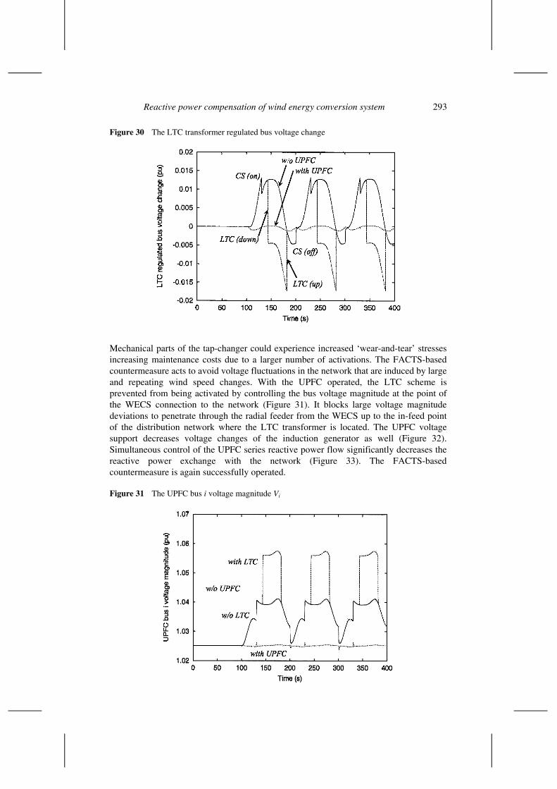
Figure 30 The LTC transformer regulated bus voltage change
Mechanical parts of the tap-changer could experience increased ‘wear-and-tear’ stresses increasing maintenance costs due to a larger number of activations. The FACTS-based countermeasure acts to avoid voltage fluctuations in the network that are induced by large and repeating wind speed changes. With the UPFC operated, the LTC scheme is prevented from being activated by controlling the bus voltage magnitude at the point of the WECS connection to the network (Figure 31). It blocks large voltage magnitude deviations to penetrate through the radial feeder from the WECS up to the in-feed point of the distribution network where the LTC transformer is located. The UPFC voltage support decreases voltage changes of the induction generator as well (Figure 32). Simultaneous control of the UPFC series reactive power flow significantly decreases the reactive power exchange with the network (Figure 33). The FACTS-based countermeasure is again successfully operated.
Figure 31 The UPFC bus i voltage magnitude Vi

294 N. Dizdarevic, M. Majstrovic and G. Andersson
Figure 32 Induction Generator 1 bus voltage magnitude
Figure 33 The UPFC bus j series reactive power flow Qj2
Reactive power compensation of wind energy conversion system 295
5.6 Isolated operation of the WECS
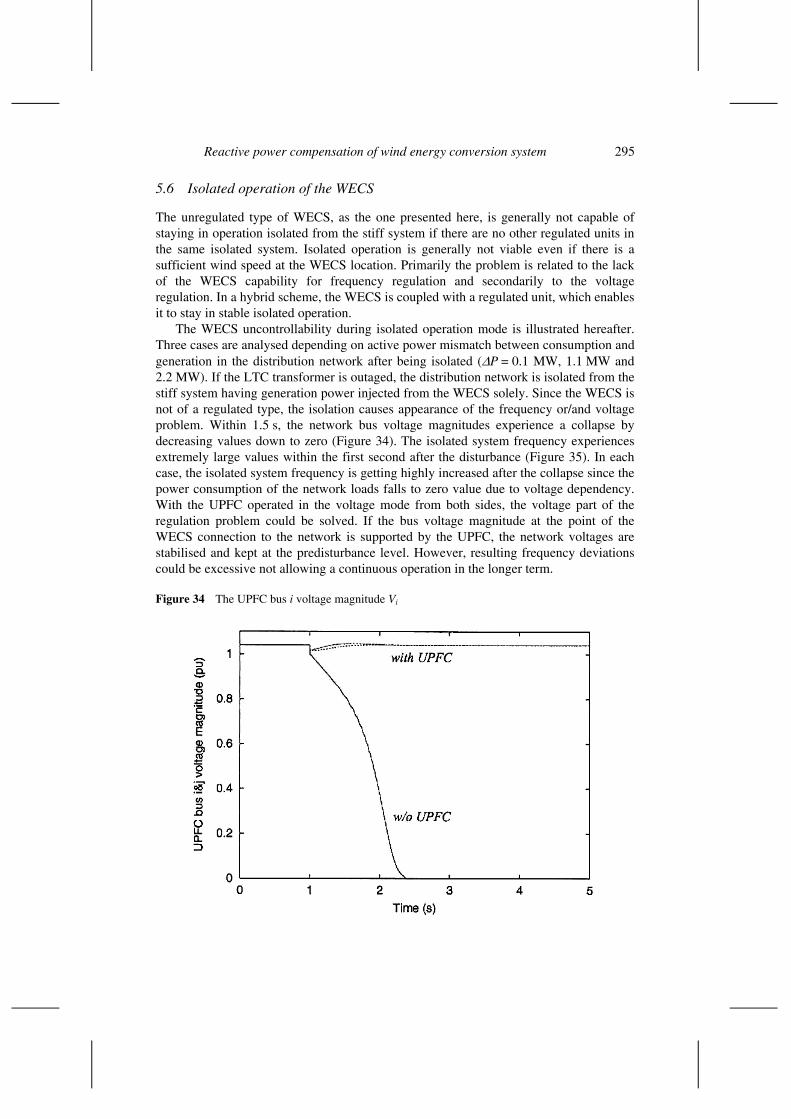
The unregulated type of WECS, as the one presented here, is generally not capable of staying in operation isolated from the stiff system if there are no other regulated units in the same isolated system. Isolated operation is generally not viable even if there is a sufficient wind speed at the WECS location. Primarily the problem is related to the lack of the WECS capability for frequency regulation and secondarily to the voltage regulation. In a hybrid scheme, the WECS is coupled with a regulated unit, which enables it to stay in stable isolated operation.
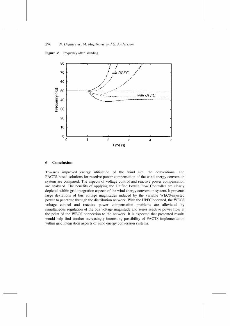
The WECS uncontrollability during isolated operation mode is illustrated hereafter. Three cases are analysed depending on active power mismatch between consumption and generation in the distribution network after being isolated (∆P = 0.1 MW, 1.1 MW and 2.2 MW). If the LTC transformer is outaged, the distribution network is isolated from the stiff system having generation power injected from the WECS solely. Since the WECS is not of a regulated type, the isolation causes appearance of the frequency or/and voltage problem. Within 1.5 s, the network bus voltage magnitudes experience a collapse by decreasing values down to zero (Figure 34). The isolated system frequency experiences extremely large values within the first second after the disturbance (Figure 35). In each case, the isolated system frequency is getting highly increased after the collapse since the power consumption of the network loads falls to zero value due to voltage dependency. With the UPFC operated in the voltage mode from both sides, the voltage part of the regulation problem could be solved. If the bus voltage magnitude at the point of the WECS connection to the network is supported by the UPFC, the network voltages are stabilised and kept at the predisturbance level. However, resulting frequency deviations could be excessive not allowing a continuous operation in the longer term.
Figure 34 The UPFC bus i voltage magnitude Vi
296 N. Dizdarevic, M. Majstrovic and G. Andersson
Figure 35 Frequency after islanding
6 Conclusion
Towards improved energy utilisation of the wind site, the conventional and FACTS-based solutions for reactive power compensation of the wind energy conversion system are compared. The aspects of voltage control and reactive power compensation are analysed. The benefits of applying the Unified Power Flow Controller are clearly depicted within grid integration aspects of the wind energy conversion system. It prevents large deviations of bus voltage magnitudes induced by the variable WECS-injected power to penetrate through the distribution network. With the UPFC operated, the WECS voltage control and reactive power compensation problems are alleviated by simultaneous regulation of the bus voltage magnitude and series reactive power flow at the point of the WECS connection to the network. It is expected that presented results would help find another increasingly interesting possibility of FACTS implementation within grid integration aspects of wind energy conversion systems.

Reactive power compensation of wind energy conversion system 297
References
Ackermann, T. et al. (2001) ‘Distributed generation: a definition’, Electric Power Systems Research, Vol. 57, pp.195–204.
Anderson, P. (1983) ‘Stability simulation of wind turbine systems’, IEEE Transactions on Power Systems, December, Vol. PAS-102, No. 12, pp.3791–3795.
Chedid, R. et al. (2000) ‘Adaptive fuzzy control for wind-diesel weak power systems’, IEEE Transactions on Energy Conversion, March, Vol. 15, No. 1, pp.71–78.
CIGRÉ (1999) ‘Impact of increasing contribution of dispersed generation on the power system’, WG 37.23, February.
CIGRÉ (2000a) ‘Modelling new forms of generation and storage’, WG 38.01, November.
CIGRÉ (2000b) ‘Unified Power Flow Controller (UPFC)’, Report TF 14–27.
Dizdarevic, N. (2001) ‘Unified power flow controller in alleviation of voltage stability problem’, PhD Thesis, University of Zagreb, Croatia, October, Online, Available at www.eihp.hr/~ndizdar
Dizdarevic, N. et al. (1999) ‘Power flow regulation by use of UPFC’s injection model’, Proceedings of the IEEE Budapest Power Tech ’99 Conference, Budapest, Hungary, August, paper BPT99–367–12.
Dizdarevic, N. et al. (2003) ‘Grid integration of wind energy conversion system’, Project Study Commissioned for Croatian Electric Company (in Croatian), Energy Institute Hrvoje Pozar, Zagreb, Croatia, February.
Gyugyi, L. et al. (1995) ‘The unified power flow controller: a new approach to power transmission control’, IEEE Transactions on Power Delivery, April, Vol. 10, No. 2, pp.1085–1097.
Hatziargyriou, N. (2002) ‘Distributed energy sources: technical challenges’, IEEE 2002 Winter Meeting, NY, USA, January.
Heier, S. (1998) Grid Integration of Wind Energy Conversion Systems, John Wiley & Sons.
Jenkins, N. et al. (2000) ‘Embedded generation’, IEEE Power and Energy Series 31, ISBN 0 85296 774 8, London, UK.
Kundur, P. (1994) ‘Power system stability and control’, EPRI McGraw-Hill, ISBN 0–07–035958–X.
Lopes, J. (2002) ‘Integration of dispersed generation on distribution network – impact studies’, IEEE 2002 Winter Meeting, NY, USA, January.
Noroozian, M. et al. (1997) ‘Use of UPFC for optimal power flow control’, IEEE Transactions on Power Delivery, October, Vol. 17, No. 4, pp.1629–1634.
Taylor, C. (1994) ‘Power system voltage stability’, EPRI McGraw-Hill, ISBN 0–07–063184–0.
298 N. Dizdarevic, M. Majstrovic and G. Andersson
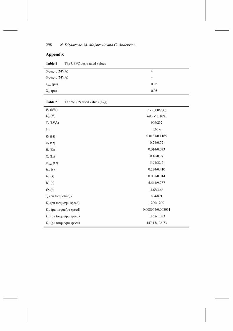
Appendix
Table 1 The UPFC basic rated values
SCONV1n (MVA) 4
SCONV2n (MVA) 4
rmax (pu) 0.05
Xk (pu) 0.05
Table 2 The WECS rated values (G/g)
Pn (kW) 7 × (800/200)
Un (V) 690 V ± 10%
Sn (kVA) 909/232
1:n 1:63.6
RS (Ω) 0.0131/0.1165
XS (Ω) 0.24/0.72
Rr (Ω) 0.014/0.073
Xr (Ω) 0.16/0.97
Xmag (Ω) 5.94/22.2
Hm (s) 0.234/0.410
Hg (s) 0.008/0.014
HT (s) 5.644/9.787
Θc (°) 3.6°/3.6°
cc (pu torque/rade) 884/821
Dc (pu torque/pu speed) 1200/1200
Dm (pu torque/pu speed) 0.008664/0.008031
Dg (pu torque/pu speed) 1.168/1.083
DT (pu torque/pu speed) 147.15/136.73