recording complex structures using close range ...€¦ · restitution of the granite stones....
TRANSCRIPT

The Photogrammetric Record 28(144): 375–395 (December 2013)DOI: 10.1111/phor.12040
RECORDING COMPLEX STRUCTURES USING CLOSERANGE PHOTOGRAMMETRY: THE CATHEDRAL OF
SANTIAGO DE COMPOSTELA
Santiago MARTÍNEZ ([email protected])Juan ORTIZ ([email protected])M
a LUZ GIL ([email protected])M
a TERESA REGO ([email protected])
University of Santiago de Compostela, Spain
Abstract
This paper describes the photogrammetric 3D modelling of complex buildingsusing low-cost automatic image matching (AIM), consumer-grade digital camerasand low-altitude imagery. To verify the potential of this method, it was applied tothe documentation of a specific case: the towers and roofs of the Cathedral ofSantiago de Compostela in Spain, a UNESCO World Heritage Site. The designand development of a mechanism for coping with the elevation, based ontelescopic masts, was essential. Models, orthophotos and plans have been obtainedto determine and rigorously measure the geometry involved. Thereby it waspossible to accurately record the materials and decorative elements based on therestitution of the granite stones. Furthermore, close range photogrammetry madethe analysis and quantification of the inclination of the south tower possible.
Keywords: 3D image-based modelling, close range, cultural heritage, historicbuilding, metric documentation, telescopic masts
Introduction
THE CATHEDRAL OF SANTIAGO DE COMPOSTELA in Spain is an architectural prodigy of greattechnical and technological intelligence and is one of the most important religioussanctuaries in the world. It is unique in that it reputedly houses the tomb of the apostleSaint James (Santiago). Its historic buildings are of exceptional value and represent thehistory and cultural memory of a community (Peg�on et al., 2004) so that its digitalsurveying for documentary and conservation objectives should be considered as necessary,beneficial and responsible.
The development plan for the cathedral defines it as an ideal subject for research, basedon modern measurement techniques, given that the excellent state of conservation of theRomanesque building and sculpture allows for many multifaceted observations.
© 2013 The Authors
The Photogrammetric Record © 2013 The Remote Sensing and Photogrammetry Society and John Wiley & Sons Ltd

When preparing for a renovation or structural improvement, the original architecturalplans may be inaccurate, if they exist at all (Arayici, 2007). Research aimed at planningconservation and/or restoration intervention of historic buildings must be based on up-to-date and precise documentation including geometric shape, architectural characteristics,materials and structural analysis (Genovese, 2005).
Grussenmeyer et al. (2008) describe the spatial data acquisition techniques currentlyused for cultural heritage documentation projects such as conventional surveying, photo-grammetry and laser scanning.
The majority of technicians currently involved in heritage conservation still usetraditional methods and techniques (Arias et al., 2007). Traditional manual methods arecommonly employed for their simplicity of use and low cost, even though their applicationcan mean the loss of information in the transmission of data from the original to thetheoretical model (Yilmaz et al., 2008) and their accuracy is, in many cases, inadequate.Furthermore, as can be seen in Barazzetti et al. (2009), a complete geometric study of anelement with irregular shapes is impossible to achieve with common topographic methodssuch as using a total station.
Photogrammetric methods (Remondino and El-Hakim, 2006), laser scanning methods(Beraldin et al., 2000) and their combination (Guidi et al., 2004) can currently generatehigh-resolution and accurate 3D models of historic buildings and can provide accuratemeasurements and objective documentation as well as different perspectives (Campana andRemondino, 2007). The 3D digitisation of architectural elements is important for continuousmonitoring of the related spatial information at different time periods (Al-kheder et al.,2009). A typical output of these techniques is a point cloud, that is, a set of points ofknown X, Y, Z coordinates retrieved from the visible surface of the object under study.Three-dimensional point clouds obtained through laser scanning methods, which arerequired for the creation of the models, are faster to survey in the field than those generatedby photogrammetry. However, the complexity and difficulty of access to specific work areasin addition to those considerations discussed in El-Hakim et al. (2005) and Chandler et al.(2005a) such as the high cost, limited portability and the need for a power supply (camerasuse cheap batteries), limits the use of laser scanning in favour of photogrammetric methodsin many applications.
The literature explains different approaches for the 3D documentation of complexstructures that are the focus of this paper. Many of these studies apply methods based onimages (Guidi et al., 2008; P�erez et al., 2011) and laser scanning (N�u~nez et al., 2012).Furthermore, some authors use multiple data sourcing techniques (combining the qualitiesand advantages of these different techniques) and have achieved very interesting results inthese kinds of structures (Fassi et al., 2011).
Digital models have now generated derivative products such as precise 2D and even3D drawings which are contributing extensively to the understanding of these complex anddetailed surfaces (Yilmaz et al., 2008). In contrast to theoretical or idealised models, thesemodels reproduce the true morphology of the object highlighting the differences betweenirregular elements or highly variable geometry (Riveiro et al., 2011).
This paper describes the process for the generation of 3D models, orthophotos andplans of the area around the P�ortico de la Gloria in the towers and roofs of the Cathedral ofSantiago de Compostela using digital close range photogrammetry. The complexity of theelement, the reduced working space in the inner fac�ades of the structure, the height anddifficult access, together with the architectural significance of the horizontal elements,required advanced and detailed planning and processing work.
Martınez et al. Recording complex structures using close range photogrammetry: Santiago Cathedral
© 2013 The Authors
The Photogrammetric Record © 2013 The Remote Sensing and Photogrammetry Society and John Wiley & Sons Ltd376

Dense Photogrammetric Matching for 3D Modelling
The increased use of 3D image-based digitalisation methods in recent years is due tothe appearance of user-friendly close range photogrammetric software packages such asPhotosculpt, 3DSOM Pro, Shapecapture, Image Master, Photomodeler Scanner and 123DCatch. There is a growing professional demand for these products from a wide range ofsectors. Proof of this is the extensive bibliography that presently exists covering a widerange of areas such as biology (Chiari et al., 2008), biomechanics (Camomilla et al., 2009),accident reconstruction (Du et al., 2009), geology (Fujii et al., 2009), structural analysis(Hampel and Maas, 2009; Riveiro et al., 2011), hydraulics (Wanek and Wu, 2006),microtopography (Abd Elbasit et al., 2009) and the possible surface modelling of Mars (Diet al., 2008). However, this increased use is most evident in the field of archaeology andcultural heritage with examples in rock and cave art (Chandler et al., 2007; Ortiz et al.,2010), buildings and monuments (Yilmaz et al., 2008; Barazzetti et al., 2011), townplanning (Koutsoudis et al., 2007; N�u~nez and Pozuelo, 2009) and extensive archaeologicalareas (Chiabrando et al., 2011; di Giacomo et al., 2011; Hendrickx et al., 2011).
Most of the work in these applications employs dense automatic image matching(AIM) on oriented image networks. The technique allows for the automatic creation ofdense point clouds from stereoscopic pairs of photographs taken with conventional cameras.This means that the program can record, from oriented photographs, the physical 3Dcoordinates of the points of the surface under study and store each one of these with its red,green and blue (RGB) chromatic information. To do this it is necessary to identify andreference each pixel (or group of pixels) of an image with its homologue in the secondimage. A description of these algorithms is available in Remondino and El-Hakim (2006),Caballo (2009) and Orteu (2009). Until recently, the software that allowed the creation ofpoint clouds comprised photogrammetric products for complex work such as the Z/IImaging SSK ImageStation from Intergraph (used by Aguilar et al. (2005) for mappingsmall areas) or Leica Photogrammetric Suite (used by Chandler et al. (2007) for recordingrock art), both designed for specialised aerial photogrammetric applications andconsequently very expensive (Chandler et al., 2005b).
The inclusion of AIM in close range photogrammetric software has raised the status ofphotogrammetry to that of other techniques such as the use of laser scanning. Examples ofcomparative studies of both techniques (Kadobayashi et al., 2004; Rizzi et al., 2007;Sturzenegger and Stead, 2009) and their combined use (El-Omari and Moselhi, 2008;Al-kheder et al., 2009; Lerma et al., 2010) confirm this. Multi-image-based matchingtechniques have also been developed and have been effectively applied to historical buildings(Koutsoudis et al., 2013). AIM now allows for the recording of X, Y, Z coordinates of severalhundred-thousand points per minute, which substantially improves on the thousand points perminute in Chandler et al. (2005b); it can digitally represent, with great detail and accuracy,the irregular surfaces of highly complex elements.
The final quality of the 3D model is directly related to the point clouds generated throughAIM and this, in turn, depends on the quality of the photographs and imaging geometry. Arealistic and uniform dense point cloud without holes and noise is achieved with frontal images(with the axis camera perpendicular to the object’s surface), which means having a stereopairfor practically each face to be modelled. With this in mind, it is clear that to survey verticalelements of low height such as walls or fac�ades, it suffices to take photographs at ground level.This does not apply, however, when modelling elements, or parts of elements, that are morehorizontally inclined irrespective of whether they are at ground level or in a more elevatedposition such as cornices or wall crowns. In these cases, therefore, it is necessary to take the
The Photogrammetric Record
© 2013 The Authors
The Photogrammetric Record © 2013 The Remote Sensing and Photogrammetry Society and John Wiley & Sons Ltd 377

photographs from the air, or from an elevated platform, with the camera in a nadir-lookingposition. Visibility occlusions and double projection problems are discussed in Al-kheder et al.(2009) where only ground-level perspectives are used.
The fundamental question is to decide at what height to elevate the camera to acquirethe point clouds; for this it is necessary to establish the required spatial resolution andaccuracy, both vertically and horizontally. The most logical way to augment the resolutionand precision of the spatial information is to move the sensor closer to the object (Smithet al., 2009). However, the higher the camera, the greater the surface area covered by thephotographs and so the more efficient the work. The height of the camera is, therefore, abalance between the requisites of accuracy/resolution and efficiency. Archaeology, forexample, requires centimetre resolution which limits the altitude to below 200 m (low-altitude photography). In many cases, the excessive rental costs of planes and helicopters,the impracticability of the target zone or flight altitude restrictions limit their use as aplatform for photography (Smith et al., 2009). Alternatively, a wide variety of devices areused to elevate the camera: paramotors, cranes, scaffolds, masts, wires, balloons, kites orunmanned aerial vehicles (UAVs) which include radio-controlled model helicopters oraircraft. These can elevate consumer-grade (non-metric) digital cameras to obtain stereophotography suitable for AIM (Chandler et al., 2005a).
Case Study: Towers and Roofs of the P�ortico De La Gloria in the Cathedral
of Santiago De Compostela
The cathedral is located in the old town of Santiago de Compostela in Galicia, north-west Spain (Fig. 1). The old town, with its Romanesque, gothic and baroque buildings, isone of the world’s most valuable architectural heritage areas and a famous pilgrimage site.The basilica, constructed following the discovery of the bones of the apostle Saint James(Santiago) in approximately AD 818, was completely destroyed, together with the city, by
(A) (B)
Fig. 1. Location of the Cathedral of Santiago de Compostela. (A) Obradoiro fac�ade of the cathedral.(B) Survey area of the roofs of the cathedral.
Martınez et al. Recording complex structures using close range photogrammetry: Santiago Cathedral
© 2013 The Authors
The Photogrammetric Record © 2013 The Remote Sensing and Photogrammetry Society and John Wiley & Sons Ltd378
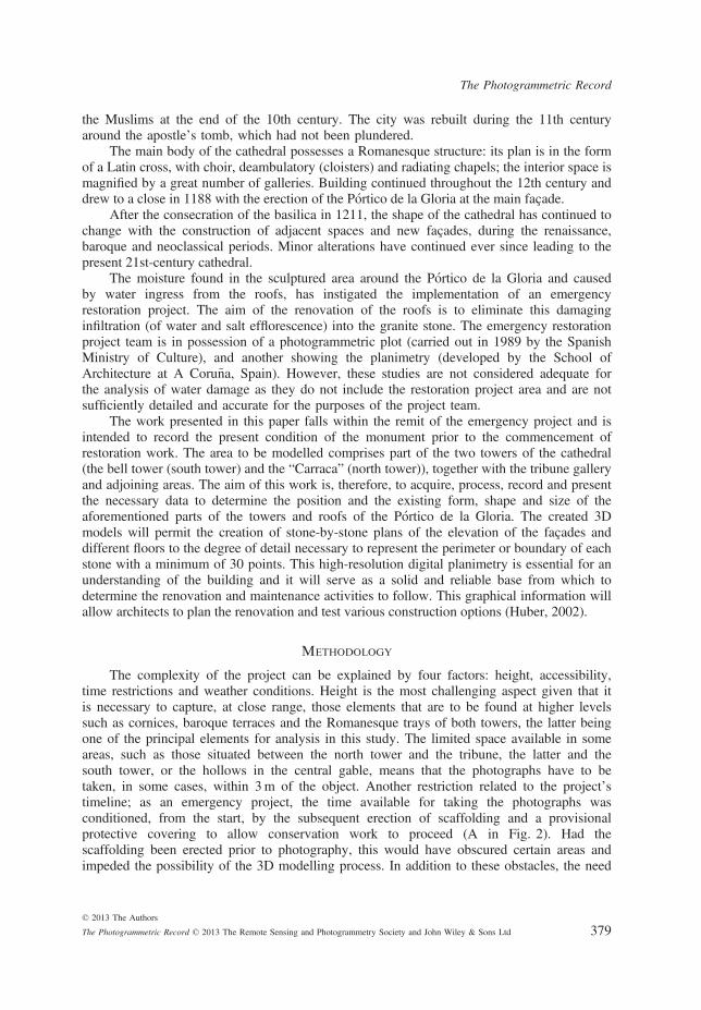
the Muslims at the end of the 10th century. The city was rebuilt during the 11th centuryaround the apostle’s tomb, which had not been plundered.
The main body of the cathedral possesses a Romanesque structure: its plan is in the formof a Latin cross, with choir, deambulatory (cloisters) and radiating chapels; the interior space ismagnified by a great number of galleries. Building continued throughout the 12th century anddrew to a close in 1188 with the erection of the P�ortico de la Gloria at the main fac�ade.
After the consecration of the basilica in 1211, the shape of the cathedral has continued tochange with the construction of adjacent spaces and new fac�ades, during the renaissance,baroque and neoclassical periods. Minor alterations have continued ever since leading to thepresent 21st-century cathedral.
The moisture found in the sculptured area around the P�ortico de la Gloria and causedby water ingress from the roofs, has instigated the implementation of an emergencyrestoration project. The aim of the renovation of the roofs is to eliminate this damaginginfiltration (of water and salt efflorescence) into the granite stone. The emergency restorationproject team is in possession of a photogrammetric plot (carried out in 1989 by the SpanishMinistry of Culture), and another showing the planimetry (developed by the School ofArchitecture at A Coru~na, Spain). However, these studies are not considered adequate forthe analysis of water damage as they do not include the restoration project area and are notsufficiently detailed and accurate for the purposes of the project team.
The work presented in this paper falls within the remit of the emergency project and isintended to record the present condition of the monument prior to the commencement ofrestoration work. The area to be modelled comprises part of the two towers of the cathedral(the bell tower (south tower) and the “Carraca” (north tower)), together with the tribune galleryand adjoining areas. The aim of this work is, therefore, to acquire, process, record and presentthe necessary data to determine the position and the existing form, shape and size of theaforementioned parts of the towers and roofs of the P�ortico de la Gloria. The created 3Dmodels will permit the creation of stone-by-stone plans of the elevation of the fac�ades anddifferent floors to the degree of detail necessary to represent the perimeter or boundary of eachstone with a minimum of 30 points. This high-resolution digital planimetry is essential for anunderstanding of the building and it will serve as a solid and reliable base from which todetermine the renovation and maintenance activities to follow. This graphical information willallow architects to plan the renovation and test various construction options (Huber, 2002).
Methodology
The complexity of the project can be explained by four factors: height, accessibility,time restrictions and weather conditions. Height is the most challenging aspect given that itis necessary to capture, at close range, those elements that are to be found at higher levelssuch as cornices, baroque terraces and the Romanesque trays of both towers, the latter beingone of the principal elements for analysis in this study. The limited space available in someareas, such as those situated between the north tower and the tribune, the latter and thesouth tower, or the hollows in the central gable, means that the photographs have to betaken, in some cases, within 3m of the object. Another restriction related to the project’stimeline; as an emergency project, the time available for taking the photographs wasconditioned, from the start, by the subsequent erection of scaffolding and a provisionalprotective covering to allow conservation work to proceed (A in Fig. 2). Had thescaffolding been erected prior to photography, this would have obscured certain areas andimpeded the possibility of the 3D modelling process. In addition to these obstacles, the need
The Photogrammetric Record
© 2013 The Authors
The Photogrammetric Record © 2013 The Remote Sensing and Photogrammetry Society and John Wiley & Sons Ltd 379

to protect the equipment being used from the rain must be mentioned as it rained for a totalof 20 days during the month in which the survey took place.
With these considerations in mind, close range photogrammetry was selected todevelop the plans and to model, with the required resolution, the highest zones or upward-facing surfaces, with the resulting financial and time costs. When it was necessary to speedup data recovery, because of weather conditions, the 3D photogrammetric survey, contraryto what might be supposed, allowed for the rapid completion of fieldwork, photography andpost-processing record analysis.
The cost of a complete photogrammetric set of equipment (including software, camera,PC and accessories) did not exceed €6000 (purchased in 2011). The existence of flush-jointed stones, which are only identifiable for restitution through photography, also makesclose range photogrammetry a particularly suitable technique for this purpose. Laser scannertechnology, given its high cost, transport difficulties, time investment and the complexity ofits data management, gives rise to problems of implementation when applied to certain areasof fieldwork (Campana and Remondino, 2007).
Equipment
The software used in the present work was Photomodeler Scanner 2011, version 6.3.3(Eos Systems, Vancouver, Canada). The photographs were taken with a Canon EOS 550D
(A)
(B)
(C) (D)
(E)
Fig. 2. Taking photos on the roofs. A shows the scaffolding. B, C and D depict the consumer-grade cameraand tripod, E shows lifting the telescopic mast and the aerial poppet-head.
Martınez et al. Recording complex structures using close range photogrammetry: Santiago Cathedral
© 2013 The Authors
The Photogrammetric Record © 2013 The Remote Sensing and Photogrammetry Society and John Wiley & Sons Ltd380

camera with a CMOS sensor of 18 megapixels (51849 3456 pixels; 22�3mm9 14�9mm).This non-metric digital camera was used in conjunction with a Canon EF 20mm 1:2�8objective lens. The pixel size was 4�3 lm9 4�3lm.
Alternative systems to elevate the camera were considered. Kites are the most economicand are appropriate for a range of applications because they can be launched quickly from theground (Aber et al., 2002). However, the need for suitable wind speed conditions, limitedmanoeuvrability and the presence of vertical elements invalidate their use in this project.Balloons and dirigibles are also economically attractive but, like kites, are susceptible to windconditions (Johnson et al., 1990) which can compromise the photographic equipment and dataquality. UAVs are, generally, much more expensive and their rental requires the assistance of atrained operator (Eisenbeiss, 2009). A telescopic camera mount (or mast), like kites, balloonsand dirigibles, is inexpensive but is much less susceptible to wind conditions. Their use iscommon in the professional world of photography as a result of their portability andmanoeuvrability in the field, although the latter consideration depends on the height at whichone is working. An example of the use of a mast in photogrammetry, applied to monitoringstreams, can be seen in Bird et al. (2010). Other devices often successfully used inphotogrammetry, such as scissor lifts, articulating booms or telescopic booms, cannot beemployed in this study because of ground features and accessibility in the project area.
The mast was selected as the most suitable device for this study because of the need togenerate plans from a 3D model with high resolution and accuracy in a complex environment(in terms of its geometry and location), the adverse weather conditions and considerable spatiallimitations. The elevation device designed comprises three principal parts: the lift telescopicmast (LTM), the aerial poppet-head (APH) and the ground control unit (GCU). The LTM is acommercial manually extendible device and is constructed of lightweight materials (aluminiumand plastic). The working length of the mast is set at 5m and the APH is mounted on the topof the LTM. The APH is of two types: when the LTM is positioned vertically, a simple APH(s-APH) is selected with movement about the vertical axis (only) and operated manually (E inFig. 2). However, when the LTM is positioned horizontally, a complex APH (c-APH), withmovement about both the vertical and horizontal axes, is used and operated by remote control.In both cases, the APH has a remotely controlled trigger and wireless video transmitter. TheGCU comprises multimedia glasses and a wireless video receiver which allows for theinstantaneous visualisation of the camera view; it is equipped with a live-view function and ahand-held radio-controlled device for controlling the camera rotations (azimuth and tilt) andthe shutter. The s-APH substitutes the radio-controlled device with a simple system of cordsand a trigger operated at a distance by a cable. The device is designed to be operated by eitherone person (LTM in a vertical position with a s-APH) or two people (LTM in a horizontalposition with a c-APH).
Additional metric instruments included a Pentax R-326EX total station with a miniprism and a 5m long steel tape measure, with a maximum error of 1�3mm, which are usedin order to georeference the model and check the accuracy. Targets, a PC, a computer-aideddesign (CAD) program for the restitution, a tripod and a folding ladder complete thenecessary equipment to develop this methodology.
Photogrammetric 3D Modelling Process
The methodology involved is based on images derived from AIM and is composed ofthe four simple steps outlined by Remondino and El-Hakim (2006): design; 3D measure-ment; structuring and modelling; and texturing and visualisation. The methodology in thispaper includes a fifth step: the evaluation of the accuracy of the acquired 3D
The Photogrammetric Record
© 2013 The Authors
The Photogrammetric Record © 2013 The Remote Sensing and Photogrammetry Society and John Wiley & Sons Ltd 381
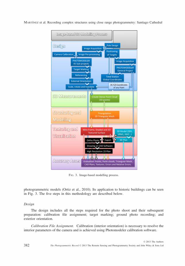
photogrammetric models (Ortiz et al., 2010). Its application to historic buildings can be seenin Fig. 3. The five steps in this methodology are described below.
Design
The design includes all the steps required for the photo shoot and their subsequentpreparation: calibration file assignment; target marking; ground photo recording; andexterior orientation.
Calibration File Assignment. Calibration (interior orientation) is necessary to resolve theinterior parameters of the camera and is achieved using Photomodeler calibration software.
Fig. 3. Image-based modelling process.
Martınez et al. Recording complex structures using close range photogrammetry: Santiago Cathedral
© 2013 The Authors
The Photogrammetric Record © 2013 The Remote Sensing and Photogrammetry Society and John Wiley & Sons Ltd382
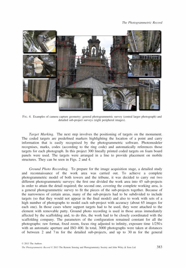
Target Marking. The next step involves the positioning of targets on the monument.The coded targets are predefined markers highlighting the location of a point and carryinformation that is easily recognised by the photogrammetric software. Photomodelerrecognises, marks, codes (according to the ring code) and automatically references thosetargets for each photograph. In this project 300 lineally printed coded targets on foam boardpanels were used. The targets were arranged in a line to provide placement on mobilestructures. They can be seen in Figs. 2 and 4.
Ground Photo Recording. To prepare for the image acquisition stage, a detailed studyand reconnaissance of the work area was carried out. To achieve a completephotogrammetric model of both towers and the tribune, it was decided to carry out twodifferent photogrammetric surveys: the first one divided the work area into 45 sub-projectsin order to attain the detail required; the second one, covering the complete working area, isa general photogrammetric survey to fit the pieces of the sub-projects together. Because ofthe narrowness of certain areas, many of the sub-projects had to be subdivided to includetargets (so that they would not appear in the final model) and also to work with sets of ahigh number of photographs to model each sub-project with accuracy (about 65 images foreach one). In those cases where support targets had to be used, they were attached to theelement with removable putty. Ground photo recording is used in those areas immediatelyaffected by the scaffolding and, to do this, the work had to be closely coordinated with thescaffolding company. The parameters of the configuration remained constant for all thephotographs: raw format, fixed zoom, focus ring adjusted to infinity, exposure time 1/250 swith an automatic aperture and ISO 400. In total, 3000 photographs were taken at distancesof between 2 and 7m for the detailed sub-projects, and up to 30 m for the general
Fig. 4. Examples of camera capture geometry: general photogrammetric survey (central larger photograph) anddetailed sub-project surveys (eight peripheral images).
The Photogrammetric Record
© 2013 The Authors
The Photogrammetric Record © 2013 The Remote Sensing and Photogrammetry Society and John Wiley & Sons Ltd 383
photogrammetric survey. Consequently, the object pixel size varied between 0�4mm90�4mm and 1�5mm9 1�5mm (Fig. 4).
Exterior Orientation. Once the photographs are taken, it is necessary to reference themand to proceed with the exterior orientation to scale, translate and rotate the 3D digitalmodel of each of the 45 sub-projects. These three steps were achieved on the basis of thecoordinates of three points in each sub-project, which were obtained with another generalphotogrammetric survey which was previously carried out using targets, total station and thesame photogrammetric equipment. A system of general coordinates was applied based ontwo existing survey control marks located on the ridges of the cathedral. This generalsurvey, based on these coordinates, can accurately determine the X, Y, Z coordinates of anyindentation, discolouration, crack, target and other feature, existing in the work area and soscale, move and rotate the 3D model of each sub-project to generate the complete model.The topographic surveying was performed basically from one station placed on one of theknown marks of the ridge, but in order to register certain details of the working area, twonew stations were located beside each tower (in the places shown in the two lowerphotographs in Fig. 4). Their positions were fixed by using the intersection method.
3D Measurements
The referenced dense point cloud is automatically created from a stereopair with aknown external orientation. The 3D surface is measured in a routine procedure integrated inthe software which correlates textured areas of stereoscopic pairs using AIM for a cloud ofcoloured points which represents the morphology of the surface of the element.
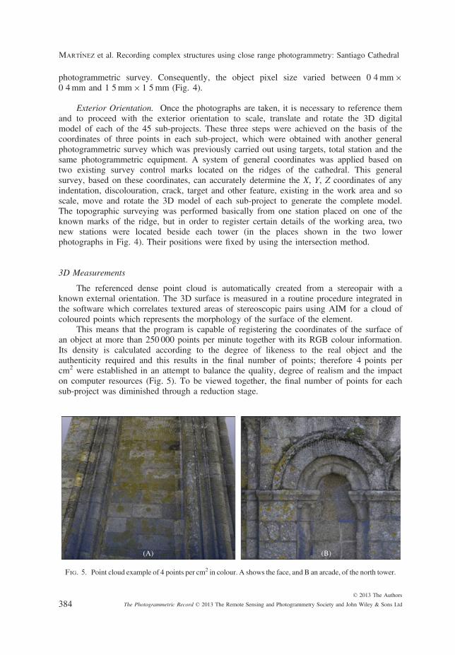
This means that the program is capable of registering the coordinates of the surface ofan object at more than 250 000 points per minute together with its RGB colour information.Its density is calculated according to the degree of likeness to the real object and theauthenticity required and this results in the final number of points; therefore 4 points percm2 were established in an attempt to balance the quality, degree of realism and the impacton computer resources (Fig. 5). To be viewed together, the final number of points for eachsub-project was diminished through a reduction stage.
(A) (B)
Fig. 5. Point cloud example of 4 points per cm2 in colour. A shows the face, and B an arcade, of the north tower.
Martınez et al. Recording complex structures using close range photogrammetry: Santiago Cathedral
© 2013 The Authors
The Photogrammetric Record © 2013 The Remote Sensing and Photogrammetry Society and John Wiley & Sons Ltd384

Structuring and Modelling
Once the point cloud was obtained, it was transformed onto a polygonal surface.Polygons, in this case triangles, are usually the most flexible way to accurately represent theresults of 3D measurements and provide an optimal surface description (Remondino and El-Hakim, 2006). This step involves the triangulation of all points to obtain a 3D triangulatedirregular network (TIN). Every sub-project is constructed of between 200 000 and 500 000triangles.
Texturing, Visualisation and Photogrammetric Restitution
Following the creation of the polygonal grid, the results can be visualised in wire-frame form, using a shaded and/or textured mode. Once the internal and externalorientations of the images are known, their corresponding coordinates are calculated foreach vertex of each triangle on the 3D surface. The RGB colour values of each triangle inthe project are then linked to the surface (Remondino and El-Hakim, 2006). In this work,textures have been assigned manually; even though the program can do this automatically, itcannot process criteria such as light quality, focusing or the presence of objects extraneousto the building (such as scaffolding). In complex structures such as this one, the aestheticresults are often inadequate if the texture assignment is not performed manually. A high-quality 3D model with photorealistic texture is obtained for each sub-project. An orthophotois then created with Photomodeler and can be exported to any CAD program for thephotogrammetric restitution to plot the plan.
Accuracy Assessment
In order to evaluate the success of the project output, it is necessary to review theaccuracy of the photogrammetric work and the validity of the 3D model output. It isimportant to achieve a good finish in the models at an aesthetic level and to determine towhat extent the dimensions of the model correspond with reality; accuracy therefore has tobe assessed. As can be seen in the sequence in Fig. 6, photogrammetry allows for the
(A) (B) (C)
Fig. 6. Triangulation (A), shadowing (B) and texturing (C) of the cornice and baroque terrace of the north tower.
The Photogrammetric Record
© 2013 The Authors
The Photogrammetric Record © 2013 The Remote Sensing and Photogrammetry Society and John Wiley & Sons Ltd 385

analysis of errors at diverse stages of the modelling process: point clouds, triangular meshor plan development. It is also possible to establish if the textures are correctly positionedor not. As the plan is developed on the basis of an orthophoto and this, in turn, is based onthe 3D model, errors will have accumulated so that, by studying the accuracy of the finalproduct, it is possible to determine the maximum error in the plans and whether it isacceptable or not. An accurate control system, depending on the 3D model application, hasto be established. In fact with some applications, such as virtual tourism, precise geometryis not as critical as the photometric accuracy (Huber, 2002), but in other cases, includingthe current Santiago Cathedral work, this aspect is crucial.
The quality of the measurements, carried out with Photomodeler, is determined by themetric quality of 20 distances between 40 check points randomly distributed throughout theproject. The distances between check points were measured with a steel tape, valid forchecking accuracy at this scale. The check points were identified in the plans and thedistances between them were directly calculated in the CAD application used for therestitution. The error recorded in these measurements between check points was thenanalysed.
The metric quality of the method was tested using some descriptive statistics of the errorand a t-test paired two samples for means. The t-test was run in Microsoft Office by comparingthe tape measurements with the transformed distance value obtained on the final plan.
With regard to the accuracy of the photogrammetry, the mean error of the 20observations is below 1�3mm with a maximum absolute error value of 10mm. Table Ishows the descriptive statistics of the accuracy assessment on the final plan of the cathedral.Based on these statistics, the photogrammetric method shows a high metric quality.
Table I. Results obtained at the accuracy assessment stage for 20 check distances.
Truedistance (m)
Plan distance(m)
Error(m)
Absolute errorvalue (mm)
2�783 2�783 0�000 0�0003�015 3�017 �0�002 0�0021�470 1�477 �0�007 0�0070�794 0�794 0�000 0�0003�029 3�025 0�004 0�0043�573 3�573 0�000 0�0001�606 1�607 �0�001 0�0013�492 3�485 0�007 0�0072�631 2�638 �0�007 0�0073�330 3�324 0�006 0�0062�923 2�933 �0�010 0�0100�946 0�951 �0�005 0�0054�661 4�663 �0�002 0�0023�025 3�031 �0�006 0�0061�285 1�280 0�005 0�0051�486 1�487 �0�001 0�0011�133 1�132 0�001 0�0010�709 0�707 0�002 0�0022�155 2�162 �0�007 0�0072�126 2�128 �0�002 0�002Mean (m) �0�001 0�004Standard deviation (m) 0�005 0�003Minimum value (m) �0�010 0�000Maximum value (m) 0�007 0�010RMS (m) 0�005
Martınez et al. Recording complex structures using close range photogrammetry: Santiago Cathedral
© 2013 The Authors
The Photogrammetric Record © 2013 The Remote Sensing and Photogrammetry Society and John Wiley & Sons Ltd386

Results and Discussion
The 3D surveying of this monument has been a challenge because of its complexity.First, the need to acquire high-quality photographs requires a very good knowledge ofdigital photography. Second, the planning of such a project requires significant experiencein photogrammetry, given that this is the key to success in any complex project. Third, therequired use of targets to obtain a high degree of accuracy is an additional difficulty withthe technique.
With regard to simplicity and cost-effectiveness, only one team of two people using asingle camera were required to meet the deadlines; the cost of equipment, approximately€6000, includes the camera, software, mast and PC. The entire project was completed bytwo people over a period of 22 weeks: the photography took 8 weeks; the orthophotos and3D models were obtained over a period of 6 weeks while the stone-by-stonephotogrammetric restitution lasted 8 weeks.
The use of a mast to take “aerial” photographs can capture details in the highest areassuch as the Romanesque trays or the horizontal platforms in baroque decoration, and avoidsthe visibility occlusions and double projection problems when only ground-levelperspectives are used. In the latter case, the computer program extrapolates the occludedarea which clearly means a loss of realism and objectivity in the shaded 3D model andresults in errors in the designation of the texture. This, in turn, affects the quality of theorthophotos and the plans. The use of the elevated camera mount system is decisive inobtaining photographs at close range in the highest and most inaccessible areas andachieving viewpoints essential for obtaining 3D models with the degree of detail anddefinition required.
The 3D modelling process resulted in a cloud of several hundreds of thousands ofpoints for each sub-project and the corresponding surface, once structured and modelled,was formed by thousands of triangles. All sub-projects were merged together: the 3Dmodels were joined with Photomodeler in a single file employing the coordinates of thegeneral photogrammetric survey to create the complete 3D model of the project (Fig. 7). Inaddition, all sub-projects were merged with CAD software following the photogrammetricrestitution of each sub-project (Fig. 8). The degree of detail achieved in the modelling ofthe various complex elements, such as the rose windows, can be seen in Fig. 9. Detailedphoto-textured and shaded 3D visualisations and a 3D model of accessible parts can be seenin Fig. 10. It should be pointed out that these models are complete and include all thesurfaces in the work area, whatever their orientation and irrespective of the complexity ofthe various fac�ades and elements. The 3D models generated are then exported in variousdigital formats (such as 3DS, 3DM, VRML and KMZ).
All areas were modelled to the required resolution (4 points/cm2). The density of thepoint clouds is very regular throughout the project. The generated orthophoto (Fig. 11) hasa very high resolution given that the photographs were taken at close range to allow for thehigh level of detail (Fig. 12). The high-resolution orthophotos, obtained through close rangephotogrammetry, allowed complex details to be easily drawn and with a precision in theorder of millimetres irrespective of the size of the structure. This degree of precision can beachieved thanks to the high quality of the 3D model, the high-resolution orthophoto and thehigh number of points per restituted stone. The use of targets during the exterior orientationstep automated the process which again contributed to the high level of precision. The useof an algorithm capable of determining these points without targets under different viewingconditions, included in Photomodeler Scanner, was experimented with. However, the results
The Photogrammetric Record
© 2013 The Authors
The Photogrammetric Record © 2013 The Remote Sensing and Photogrammetry Society and John Wiley & Sons Ltd 387

obtained were worse and demonstrate that targets are necessary to assemble multiple sub-projects in highly complex elements of this type.
It is also possible to digitise directly on the record of very dense point clouds, takingadvantage of the fact that each point contains RGB information as if it were a photograph(using a screenshot). This system is accurate and fast with clouds of very high density andit is effective when used in the restitution process of elements of small dimensions, but it isimpracticable to proceed with it when the structure is too large.
In terms of the utility of the 3D model output for the analysis of historic buildings, theway conservation specialists (architects, restorers, archaeologists, cultural heritage conser-vationists and so on) document and analyse panels is likely to improve considerably withcurrent 3D data following the described methodology. Digital photography, in addition toallowing a high-resolution and photo-realistic 3D model of an object, provides 2D and 3Dinformation in different formats and media.
The photographic set, created by the project, can also be used to analyse and study theelement in conjunction with the model itself and the 2D and 3D restitutions. In a monumentwhich is the size and complexity of a cathedral, the development of the plans defining itsconstruction is expensive but essential for an understanding of the building and as a solid basisfor future developmental activity. Thus, the greater the quality of these plans, the moreeffective and reliable the subsequent development will be. For example, in the current study3D recording using close range photogrammetry has permitted the analysis and quantificationof the inclination of the south tower of the cathedral (approximately 2%) as can be appreciatedin Fig. 8 (left side). (It should be pointed out that an inclination of the south tower wasdetected and rectified between 1667 and 1670 (Navascu�es and Sarthou, 1997).)
The inclination of the pilasters can be easily seen when observing the tower between thelower roof and the baroque cornices of the balcony. Analysing the plan from bottom to top, thelower stairs that give access to the door of the fac�ade are horizontal. The pilasters and rows ofstone between the roof and the intermediate tray are inclined at 2% with respect to the vertical.The pilasters between the intermediate tray and the upper cornice have two clear sections; a
(A) (B)
Fig. 7. Complete 3D model of the working area. A shows a general top perspective and B the north tower fac�ade.
Martınez et al. Recording complex structures using close range photogrammetry: Santiago Cathedral
© 2013 The Authors
The Photogrammetric Record © 2013 The Remote Sensing and Photogrammetry Society and John Wiley & Sons Ltd388

lower part which is inclined at 2% and an upper part, about 1�5m long, which is almostvertical. The intermediate tray is also inclined at 2% while the upper cornice is practicallyhorizontal. The distortion is also reflected in the floor level of the balcony which corresponds
(A)
(B)
Fig. 8. Complete photogrammetric restitution of the working area on the roofs of the cathedral. A shows theelevation and B the floor plans. The south tower is on the left and the north tower on the right.
(A) (B) (C)
Fig. 9. Detail of one of the rose windows of the tribune. A shows the shaded model, B the textured model andC the photogrammetric restitution.
The Photogrammetric Record
© 2013 The Authors
The Photogrammetric Record © 2013 The Remote Sensing and Photogrammetry Society and John Wiley & Sons Ltd 389

to the baroque cornices. It can be seen from the plan that the passages are not orthogonal incontrast to those in the north tower.
Summary and Conclusion
This paper has presented the methodology used to establish a documentation system forcomplex historic buildings using digital photogrammetry. The use of relatively low-costcommercial software (Photomodeler Scanner), consumer-grade digital cameras, a mast as anelevation system and a total station for georeferencing have been used to produce dense pointclouds. The paper has also described the process for producing high-quality CAD plans on thebasis of orthophotos created from the model itself. The documentation generated isfundamental to the comprehensive monitoring, protection and maintenance planning forhistoric buildings which, given their exposure to the elements, are slowly deteriorating. The3D digital model of a historic building represents a permanent record and a reference forposterity. This work demonstrates the potential of this technique for the development of highly
(A) (B) (C)
Fig. 10. Detail of an arcade of the north tower. A is an example of a section of the shaded model. B showsthe corresponding textured model and C the complete 3D shaded model.
(A) (B) (C)
Fig. 11. A is an orthophoto of the south fac�ade of the north tower. B indicates the level of high resolutiondetail in the inset box in A. C shows the resulting photogrammetric restitution of the same inset area.
Martınez et al. Recording complex structures using close range photogrammetry: Santiago Cathedral
© 2013 The Authors
The Photogrammetric Record © 2013 The Remote Sensing and Photogrammetry Society and John Wiley & Sons Ltd390

detailed models, orthophotos and complete plans of historic buildings in complex conditionsand with limited space. Close range photogrammetry allows for the creation of accurate 3Dmodels using the same equipment and irrespective of the size of the element; there is no needto invest in multiple items of equipment depending on the size of the structures surveyed.
It is important to note that highly detailed digital models are usually applied toarchitectural monuments of great value, as in the present case of the Cathedral of Santiago deCompostela. However, their use in less significant projects can be excessive for reasons oftime and cost. Nevertheless, one of the most attractive aspects of photogrammetry is thepossibility to adjust the level of detail in the same set of photographs and work with models ofless dense point clouds. The prospect also exists, with advances in technology, of being able toimprove on the results using photographs that have already been taken. Such photographs,taken with simple photogrammetric criteria, become documentation that is capable, in thefuture, of being transformed into a three-dimensional model with greater precision.
The application of close range photogrammetry in combination with a mast allowshigh-quality 3D models to be obtained at an accessible price which transforms it into a verycompetitive methodology. As a result, close range photogrammetry has been presented as a3D documentation system that is accurate and capable of competing with other moderntechniques such as the laser scanner, which is also widely used with these structures.
With this documentation, the areas requiring intervention can be established and it canfunction as a basis for derived maps for other specialist areas such as humidity detection,micro-organism research, salt deposits, identification of anthropic damage, fissures andgeneral damage. The graphical documentation obtained provides the medium from whichthe structural behaviour of the monument can be studied as, fundamentally, it depends onits geometry. Accordingly, it has permitted the detection of the inclination of the southtower of the cathedral. The vertical alignment of the higher sections of the pilasters and the
(A)
(B)
Fig. 12. A shows the detail of the photogrammetric restitution of the arcades and Bof the baroque cornice of the north tower.
The Photogrammetric Record
© 2013 The Authors
The Photogrammetric Record © 2013 The Remote Sensing and Photogrammetry Society and John Wiley & Sons Ltd 391

horizontal inclination of the higher cornice are probably due to the restoration work carriedout between 1667 and 1670.
The 3D model created can be used for other purposes such as education or so-called“musealisation” (a virtual museum) and will allow scientists to view and study the targetobject in new ways and from different perspectives. Virtual tourism, for example, will allow“visitors” to interact and explore monuments without physical travel. In addition, thepossibility of interacting with, and studying, 3D models remotely will contribute to theircultural diffusion. By demonstrating the benefits of the technique, it is hoped to encourageconservationists to test it out in their work.
Further studies in the field of photogrammetry could lead towards fully automating theprocess of desk-based 3D modelling without a loss of accuracy. The majority of the sub-processes are, at present, automatic, but some of them, such as the creation of a 3D surfacemodel (with or without photo-texture), require a manual approach. Photomodeler Scanneruses algorithms that currently work on only two images and it is necessary to manuallyselect each stereopair to create point clouds and, in many cases, manually edit them oncethey are generated.
Nowadays, digital multi-view 3D reconstruction algorithms allow for the production of3D models of high precision and photorealistic quality based on a collection of disorderedimages of a scene or object, taken from different points of view. Use of this multi-imageapproach in combination with UAVs could be a starting point for future work.
references
Abd Elbasit, M. A. M., Anyoji, H., Yasuda, H. and Yamamoto, S., 2009. Potential of low cost close-range photogrammetry system in soil microtopography quantification. Hydrological Processes, 23(10):1408–1417.
Aber, J. S., Aber, S. W. and Pavri, F., 2002. Unmanned small-format aerial photography from kites foracquiring large-scale, high-resolution, multiview-angle imagery. International Archives of Photogrammetry,Remote Sensing and Spatial Information Sciences, 34(1). 6 pages.
Aguilar, M. A., Aguilar, F. J. and Ag€uera, F., 2005. Mapping small areas using a low-cost closerange photogrammetric software package with aerial photography. Photogrammetric Record, 20(112):335–350.
Al-kheder, S., Al-shawabkeh, Y. and Haala, N., 2009. Developing a documentation system for desertpalaces in Jordan using 3D laser scanning and digital photogrammetry. Journal of Archaeological Science,36(2): 537–546.
Arayici, Y., 2007. An approach for real world data modelling with the 3D terrestrial laser scanner for builtenvironment. Automation in Construction, 16(6): 816–829.
Arias, P., Caama~no, J. C., Lorenzo, H. and Armesto, J., 2007. 3D modeling and section properties ofancient irregular timber structures by means of digital photogrammetry. Computer-Aided Civil andInfrastructure Engineering, 22(8): 597–611.
Barazzetti, L., Binda, L., Cucchi, M., Scaioni, M. and Taranto, P., 2009. Photogrammetricreconstruction of the My Son G1 temple in Vietnam. International Archives of Photogrammetry, RemoteSensing and Spatial Information Sciences, 38(5/W1). 8 pages.
Barazzetti, L., Binda, L., Scaioni, M. and Taranto, P., 2011. Photogrammetric survey of complexgeometries with low-cost software: application to the “G1” temple in Myson. Vietnam. Journal of CulturalHeritage, 12(3): 253–262.
Beraldin, J.-A., Blais, F., Boulanger, P., Cournoyer, L., Domey, J., El-Hakim, S. F., Godin, G.,Rioux, M. and Taylor, J., 2000. Real world modelling through high resolution digital 3D imaging ofobjects and structures. ISPRS Journal of Photogrammetry and Remote Sensing, 55(4): 230–250.
Bird, S., Hogan, D. and Schwab, J., 2010. Photogrammetric monitoring of small streams under a riparianforest canopy. Earth Surface Processes and Landforms, 35(8): 952–970.
Caballo, M. P., 2009. Development and analysis of algorithms for the optimisation of automatic imagecorrelation. Master’s thesis, Karl Franzens University, Graz, Austria. 101 pages.
Martınez et al. Recording complex structures using close range photogrammetry: Santiago Cathedral
© 2013 The Authors
The Photogrammetric Record © 2013 The Remote Sensing and Photogrammetry Society and John Wiley & Sons Ltd392

Camomilla, V., Donati, M., Stagni, R. and Cappozzo, A., 2009. Non-invasive assessment of superficial softtissue local displacements during movement: a feasibility study. Journal of Biomechanics, 42(7): 931–937.
Campana, S. and Remondino, F., 2007. Fast and detailed digital documentation of archaeological excavationsand heritage artifacts. 35th Computer Applications and Quantitative Methods in Archaeology Conference,Berlin, Germany. 36–42.
Chandler, J. H., Fryer, J. G. and Jack, A., 2005a. Metric capabilities of low-cost digital cameras for closerange surface measurement. Photogrammetric Record, 20(109): 12–26.
Chandler, J. H., Fryer, J. G. and Kniest, H. T., 2005b. Non-invasive three-dimensional recording ofAboriginal rock art using cost-effective digital photogrammetry. Rock Art Research, 22(2): 119–130.
Chandler, J. H., Bryan, P. and Fryer, J. G., 2007. The development and application of a simplemethodology for recording rock art using consumer-grade digital cameras. Photogrammetric Record,22(117): 10–21.
Chiabrando, F., Nex, F., Piatti, D. and Rinaudo, F., 2011. UAV and RPV systems for photogrammetricsurveys in archaeological areas: two tests in the Piedmont region (Italy). Journal of ArchaeologicalScience, 38(3): 697–710.
Chiari, Y., Wang, B., Rushmeier, H. and Caccone, A., 2008. Using digital images to reconstruct three-dimensional biological forms: a new tool for morphological studies. Biological Journal of the LinneanSociety, 95(2): 425–436.
Di, K., Xu, F., Wang, J., Agarwal, S., Brodyagina, E., Li, R. and Matthies, L., 2008. Photogrammetricprocessing of rover imagery of the 2003 Mars Exploration Rover mission. ISPRS Journal ofPhotogrammetry and Remote Sensing, 63(2): 181–201.
di Giacomo, G., Ditaranto, I. and Scardozzi, G., 2011. Cartography of the archaeological surveys takenfrom an Ikonos stereo-pair: a case study of the territory of Hierapolis in Phrygia (Turkey). Journal ofArchaeological Science, 38(9): 2051–2060.
Du, X., Jin, X., Zhang, X., Shen, J. and Hou, X., 2009. Geometry features measurement of traffic accident forreconstruction based on close-range photogrammetry. Advances in Engineering Software, 40(7): 497–505.
Eisenbeiss, H., 2009. UAV photogrammetry. Doctoral thesis, ETH Zurich, Switzerland. 237 pages.El-Hakim, S. F., Beraldin, J.-A., Gonzo, L., Whiting, E., Jemtrud, M. and Valzano, V., 2005. A
hierarchical 3D reconstruction approach for documenting complex heritage sites. CIPA 20th InternationalSymposium, Turin, Italy. 990 pages: 790–795.
El-Omari, S. and Moselhi, O., 2008. Integrating 3D laser scanning and photogrammetry for progressmeasurement of construction work. Automation in Construction, 18(1): 1–9.
Fassi, F., Achille, C. and Fregonese, L., 2011. Surveying and modelling the main spire of Milan Cathedralusing multiple data sources. Photogrammetric Record, 26(136): 462–487.
Fujii, Y., Fodde, E., Watanabe, K. and Murakami, K., 2009. Digital photogrammetry for thedocumentation of structural damage in earthen archaeological sites: the case of Ajina Tepa. Tajikistan.Engineering Geology, 105(1–2): 124–133.
Genovese, R. A., 2005. Architectural, archaeologic and environmental restoration planning methodology:historic researches and techniques of survey aiming to conservation. CIPA 20th International Symposium,Turin, Italy. 5 pages.
Grussenmeyer, P., Landes, T., Voegtle, T. and Ringle, K., 2008. Comparison methods of terrestrial laserscanning, photogrammetry and tacheometry data for recording of cultural heritage buildings. InternationalArchives of Photogrammetry, Remote Sensing and Spatial Information Sciences, 37(B5): 213–218.
Guidi, G., Beraldin, J.-A. and Atzeni, C., 2004. High-accuracy 3D modeling of cultural heritage: thedigitizing of Donatello’s “Maddalena”. IEEE Transactions on Image Processing, 13(3): 370–380.
Guidi, G., Remondino, F., Russo, M., Rizzi, A., Voltolini, F., Menna, F., Fassi, F., Ercoli, S.,Masci, M. E. and Benedetti, B., 2008. A multi-resolution methodology for archaeological survey: thePompeii Forum. 14th International Conference on Virtual Systems and MultiMedia (VSMM), Limassol,Cyprus. 51–59.
Hampel, U. and Maas, H.-G., 2009. Cascaded image analysis for dynamic crack detection in material testing.ISPRS Journal of Photogrammetry and Remote Sensing, 64(4): 345–350.
Hendrickx, M., Gheyle, W., Bonne, J., Bourgeois, J., De Wulf, A. and Goossens, R., 2011. The useof stereoscopic images taken from a microdrone for the documentation of heritage: an example from theTuekta burial mounds in the Russian Altay. Journal of Archaeological Science, 38(11): 2968–2978.
Huber, D. F., 2002. Automatic three-dimensional modeling from reality. Doctoral thesis, The RoboticsInstitute, Carnegie Mellon University, Pittsburgh, Pennsylvania, USA. 203 pages.
Johnson, G. W., Meisner, D. E. and Johnson, W. L., 1990. Aerial photography of the Nazca Lines.Memoirs of the American Philosophical Society, 183: 271–283.
The Photogrammetric Record
© 2013 The Authors
The Photogrammetric Record © 2013 The Remote Sensing and Photogrammetry Society and John Wiley & Sons Ltd 393

Kadobayashi, R., Kochi, N., Otani, H. and Furukawa, R., 2004. Comparison and evaluation of laserscanning and photogrammetry and their combined use for digital recording of cultural heritage. InternationalArchives of Photogrammetry, Remote Sensing and Spatial Information Sciences, 35(5): 401–406.
Koutsoudis, A., Arnaoutoglou, F. and Chamzas, C., 2007. On 3D reconstruction of the old city ofXanthi. A minimum budget approach to virtual touring based on photogrammetry. Journal of CulturalHeritage, 8(1): 26–31.
Koutsoudis, A., Vidmar, B., Ioannakis, G., Arnaoutoglou, F., Pavlidis, G. and Chamzas, C., 2013.Multi-image 3D reconstruction data evaluation. Journal of Cultural Heritage. http://dx.doi.org/10.1016/j.culher.2012.12.003
Lerma, J. L., Navarro, S., Cabrelles, M. and Villaverde, V., 2010. Terrestrial laser scanning and closerange photogrammetry for 3D archaeological documentation: the Upper Palaeolithic Cave of Parpall�o as acase study. Journal of Archaeological Science, 37(3): 499–507.
Navascu�es, P. P. and Sarthou, C. C., 1997. Catedrales de Espa~na (in Spanish). Espasa Calpe, Madrid,Spain. 271 pages.
N�u~nez, A. A., Pozuelo, F. B., Marim�on, J. R. and Gisbert, A. M., 2012. Generation of virtual models ofcultural heritage. Journal of Cultural Heritage, 13(1): 103–106.
N�u~nez, M. A. and Pozuelo, F. B., 2009. Evolution of the architectural and heritage representation.Landscape and Urban Planning, 91(2): 105–112.
Orteu, J.-J., 2009. 3-D computer vision in experimental mechanics. Optics and Lasers in Engineering,47(3–4): 282–291.
Ortiz, J., Gil, M. L., Santiago, M. R., Rego, T. and Mejide, G., 2010. A simple methodology forrecording petroglyphs using low-cost digital image correlation photogrammetry and consumer-grade digitalcameras. Journal of Archaeological Science, 37(12): 3158–3169.
Peg�on, P., Pinto, A. V. and Geradin, M., 2004. Numerical modeling of stone-block monumental structures.Computers and Structures, 79: 56–81.
P�erez, A., Cachero, R., Navarro, S., Jord�a, F., L�opez, D., Lerma, J. L. and Martos, A., 2011. Digitalreconstruction of the church of San Ildefonso in Zamora (Spain) using Orthoware. International Archives ofPhotogrammetry, Remote Sensing and Spatial Information Sciences, 38(5/W16): 61–68.
Remondino, F. and El-Hakim, S. F., 2006. Image-based 3D modelling: a review. Photogrammetric Record,21(115): 269–291.
Riveiro, B., Caama~no, J. C., Arias, P. and Sanz, E., 2011. Photogrammetric 3D modelling and mechanicalanalysis of masonry arches: an approach based on a discontinuous model of voussoirs. Automation inConstruction, 20(4): 380–388.
Rizzi, A., Voltolini, F., Remondino, F., Girardi, S. and Gonzo, L., 2007. Optical measurementtechniques for the digital preservation, documentation and analysis of cultural heritage. 8th Conference onOptical 3D Measurement Techniques, Zurich, Switzerland. 16–24.
Smith, M. J., Chandler, J. and Rose, J., 2009. High spatial resolution data acquisition for the geosciences:kite aerial photography. Earth Surface Processes and Landforms, 34(1): 155–161.
Sturzenegger, M. and Stead, D., 2009. Close-range terrestrial digital photogrammetry and terrestrial laserscanning for discontinuity characterization on rock cuts. Engineering Geology, 106(3–4): 163–182.
Wanek, J. M. and Wu, C. H., 2006. Automated trinocular stereo imaging system for three-dimensionalsurface wave measurements. Ocean Engineering, 33(5–6): 723–747.
Yilmaz, H. M., Yakar, M. and Yildiz, F., 2008. Documentation of historical caravansaries by digital closerange photogrammetry. Automation in Construction, 17(4): 489–498.
R�esum�e
Cet article d�ecrit la mod�elisation 3D par photogramm�etrie d’�edifices complexes par des techniques bonmarch�e de corr�elation automatique d’images, des appareils photo du march�e et des images acquises �a bassealtitude. Le potentiel de cette m�ethode a �et�e �etudi�e en l’appliquant �a la documentation d’un cas sp�ecifique: lestours et les toits de la cath�edrale de St Jacques de Compostelle (Espagne), un site inscrit au patrimoinemondial de l’UNESCO. La conception et le d�eveloppement d’un m�ecanisme permettant des prises de vuesa�eriennes depuis un mat t�elescopique se sont av�er�es essentiels. Des mod�eles, des orthophotos et des plans ontpermis de d�eterminer la g�eom�etrie du lieu et ainsi de restituer pr�ecis�ement les structures de pierre et les�el�ements d�ecoratifs �a partir du dessin de chaque bloc taill�e. Par ailleurs, la photogramm�etrie rapproch�ee apermis l’analyse et la quantification de l’inclinaison de la tour sud.
Martınez et al. Recording complex structures using close range photogrammetry: Santiago Cathedral
© 2013 The Authors
The Photogrammetric Record © 2013 The Remote Sensing and Photogrammetry Society and John Wiley & Sons Ltd394
Zusammenfassung
Dieser Beitrag beschreibt die photogrammetrische 3D-Modellierung komplexer Geb€aude mitkosteng€unstiger automatischer Bildzuordnung (AIM), digitalen Konsumenten Kameras und Aufnahmen ausgeringer H€ohe mit Teleskopmasten. Die Methode wurde bei der Dokumentation der T€urme und D€acher derKathedrale von Santiago de Compostela in Spanien, einem UNESCO Weltkulturerbe, getestet. BesondereAufmerksamkeit wurde auf den Einsatz der Teleskopmasten gerichtet. Es wurden Modelle, Orthophotos undPl€ane abgeleitet, um die Geometrie pr€azise zu bestimmen. Dabei konnten auch die Materialien und dekorativenElemente der Granitsteine f€ur eine sp€atere Wiederherstellung ermittelt werden. Ebenso konnte eine Analyse undQuantifizierung der Neigung des S€udturmes durchgef€uhrt werden.
Resumen
Este trabajo describe el proceso de modelado 3D fotogram�etrico de edificios de gran complejidadmediante t�ecnicas de correlaci�on autom�atica de im�agenes de bajo coste, c�amaras digitales convencionales eim�agenes de baja altitud. Para verificar el potencial de este m�etodo, ha sido aplicado en la documentaci�on deun caso real: las torres y las cubiertas de la Catedral de Santiago de Compostela (Espa~na), Patrimonio de laHumanidad de la UNESCO. El dise~no y desarrollo de un mecanismo de elevaci�on basado en m�astilestelesc�opicos result�o esencial. Los modelos, ortofotos y planos obtenidos han sido usados para determinar ymedir rigurosamente de la geometría del objeto. A trav�es de ellos fue posible registrar con exactitud el estadode la cantería y de sus elementos decorativos. Adem�as, la fotogrametría de objeto cercano hizo posible elan�alisis y cuantificaci�on de la inclinaci�on de la torre sur.
© 2013 The Authors
The Photogrammetric Record © 2013 The Remote Sensing and Photogrammetry Society and John Wiley & Sons Ltd 395
The Photogrammetric Record