repot on sms-2 jspl, raigarh final
DESCRIPTION
report on sms 2 jsplTRANSCRIPT

A vocational training report On
STEEL MELTING SHOP-II
InJindal Steel & Power Limited, Raigarh
Submitted in partial fulfillment of the requirement for the
Degree in bachelor of engineering
Chhattisgarh Swami Vivekanand Technical University, Bhilai
(C.G)
Guided by: Submitted to:Mr. P.K. Mishra Mr. Vikram Singh Nanda
(Asst. Vice president) (Asst. Professor)
1

Submitted by:-Metallurgy 4th sem1) Deepak Dwivedi2) DolNarayan Patel3) Joeeta Mukherjee4) Monika Thakur5) Manish Kumar Chandra6) Prakash Kumar Nishad7) Prakash Tiwari8) Pushpraj Singh Gavel9) Rajesh Kumar Patel10) Rakesh Kumar Poddar11) Satyaprakash Patel12) Sourabh Mishra13) Swati kumar14) Tikam Singh Patel15) Sunil Gill16) Yogesh Patel
2

17) Pramod Kumar Patel18) Ravindra kumar Yadav19) Santosh Yadav
AcknowledgementWe owe our sincere gratitude to Management of JSPL to allow us for summer training. We are thankful to Mr. P.K.Mishra (Asst. Vice President-SMS-II) for allowing us to visit the different department of Steel Melting Shop.
We are also thankful to all the managers and employees of the concerned department in JSPL, Raigarh for their valuable guidance throughout the training period.
We are paying our sincere gratitude towards our eminent Principal Director Dr. B.K. Sthapak and Mr. Manish Biswas (H.R. head), we are also thankful to training and placement cell of OPJIT Mr. Nageshwar Rao and Mr. Vikram Singh Nanda for their throughout support during training.
3

ContentsS.No Topics Page no.
1. About JSPL 52. Introduction: Steel
Making6
3. Facilities at SMS-II 7-84. Electric Arc Furnace 9-115. Ladle Refining Furnace 10-196. Combi Caster 20-247. Billet Caster 25-268. Slab Caster 27-299. Tundish Unit 30-35
10. Semi Products of SMS-II 3611. Safety Aspects 3712. Conclusion 3813. Reference 39
4

About JSPL“Success with social responsibility”
Jindal Steel and Power Limited (JSPL) is one of India’s major steel producers with a significant presence in sectors like Mining, Power Generation and Infrastructure.
With an annual turnover of over US $2.9 billion, JSPL is a part of the about US $ 15 billion diversified O. P. Jindal Group and is consistently tapping new opportunities by increasing production capacity, diversifying investments, and leveraging its core capabilities to venture into new businesses. The company has committed investments exceeding US$ 30 billion in the future and has several business initiatives running simultaneously across continents.
Mr. Naveen Jindal, the youngest son of the legendary late Shri. O. P. Jindal spearheads JSPL and its group companies. The company produces economical and efficient steel and power through backward integration from its captive coal and iron-ore mines.
5

From the widest flat products to a whole range of long products, JSPL today sports a product portfolio that caters to varied needs in the steel market. The company also has the distinction of producing the world’s longest 121 metre rails and introducing large size parallel flange beams in India.
INTRODUCTIONSTEEL :-
Steel is not a specific product. It is essentially a malleable alloy of iron and one or more elements like carbon, chromium, Silicon, vanadium, etc.
Steel Making is a refining or oxidation process with the exception of reducing condition being specifically required to eliminate sulphur. The necessity to refine pig iron arises because it’s quite impure. The source of oxidizing agent needed for oxidation process steelmaking.
Steel can’t be produced directly from an iron bearing materials that occurs in nature. It is a product obtained by refining of impure iron produced by the reduction smelting of iron ore. The product obtained by reduction smelting of iron is called pig iron, if molten, and sponge iron, if solid. It contains several impurities like C, Si, Mn, P, S etc.
6
In essence, steelmaking is a process of selective oxidation of impurities i.e. reverses of iron making. In principle it resemble starting from charge preparation through melting, refining, tapping, deoxidation, decarburization, alloying, teeming, stripping or continuous casting. During steelmaking process all the impurities excepts sulphur are oxidized to their respective oxides and the oxides are eliminated either as gas or as liquid slag. Steel can be produced efficiently only if refining is adequate and clean slag and metal separation is brought about.
FACILITIES AT SMS-II (JSPL)
ANNUAL CAPACITY
2.0 MT
ELECTRIC ARC FURNACE
02 NO.
7
LADLE REFINING FURNACE
03 NO.
VACCUM DEGASSER
01 NO.
RH DEGASSER 01 NO.CONTINOUS CASTER
03 NO.
8

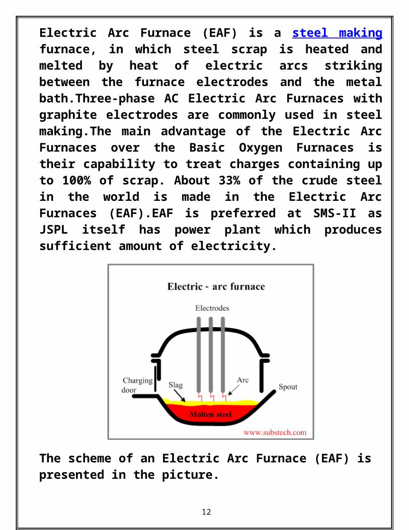
1).Electric Arc Furnace (EAF) : Electric Arc Furnace (EAF) is a steel making furnace, in which steel scrap is heated and melted by heat of electric arcs striking between the
9
furnace electrodes and the metal bath.Three-phase AC Electric Arc Furnaces with graphite electrodes are commonly used in steel making.The main advantage of the Electric Arc Furnaces over the Basic Oxygen Furnaces is their capability to treat charges containing up to 100% of scrap. About 33% of the crude steel in the world is made in the Electric Arc Furnaces (EAF).EAF is preferred at SMS-II as JSPL itself has power plant which produces sufficient amount of electricity.
The scheme of an Electric Arc Furnace (EAF) is presented in the picture.
1.1) CONSTRUCTION OF ELECTRIC ARC FURNACE :
10

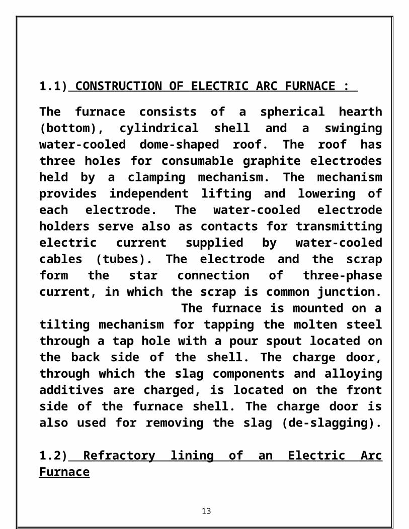
The furnace consists of a spherical hearth (bottom), cylindrical shell and a swinging water-cooled dome-shaped roof. The roof has three holes for consumable graphite electrodes held by a clamping mechanism. The mechanism provides independent lifting and lowering of each electrode. The water-cooled electrode holders serve also as contacts for transmitting electric current supplied by water-cooled cables (tubes). The electrode and the scrap form the star connection of three-phase current, in which the scrap is common junction. The furnace is mounted on a tilting mechanism for tapping the molten steel through a tap hole with a pour spout located on the back side of the shell. The charge door, through which the slag components and alloying additives are charged, is located on the front side of the furnace shell. The charge door is also used for removing the slag (de-slagging).
1.2) Refractory lining of an Electric Arc Furnace
Refractory linings of Electric Arc Furnaces are made generally of resin-bonded magnesia-carbon bricks. Fused magnesite grains and flake graphite are used as raw materials. When the bricks are heated the bonding material is coked and turns into a carbon network binding the refractory grains, preventing wetting by the slag and protecting the lining the from erosion and chemical attack of the molten metal and slag.
11
1.3) Chemical and physical processes in an Electric Arc Furnace
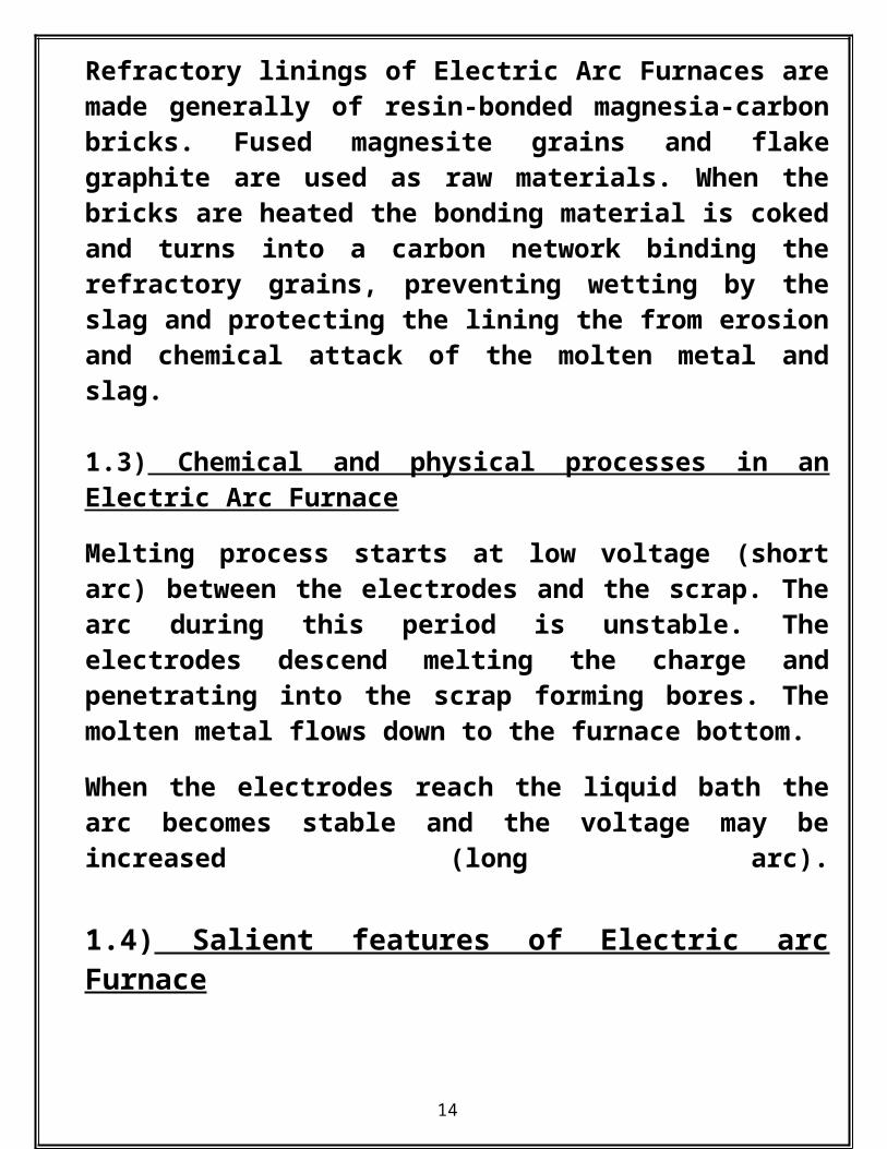
Melting process starts at low voltage (short arc) between the electrodes and the scrap. The arc during this period is unstable. The electrodes descend melting the charge and penetrating into the scrap forming bores. The molten metal flows down to the furnace bottom.
When the electrodes reach the liquid bath the arc becomes stable and the voltage may be increased (long arc).
1.4) Salient features of Electric arc Furnace
12
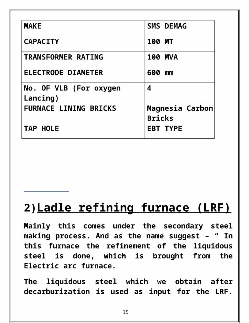
MAKE SMS DEMAG
CAPACITY 100 MT
TRANSFORMER RATING 100 MVA
ELECTRODE DIAMETER 600 mm
No. OF VLB (For oxygen Lancing)
4
FURNACE LINING BRICKS Magnesia Carbon Bricks
TAP HOLE EBT TYPE
2)Ladle refining furnace (LRF)Mainly this comes under the secondary steel making process. And as the name suggest – “ In this furnace the refinement of the liquidous steel is done, which is brought from the Electric arc furnace.”
The liquidous steel which we obtain after decarburization is used as input for the LRF. It also plays important role for deciding the grade of the steel.
2.1)Operation & process in LRF.
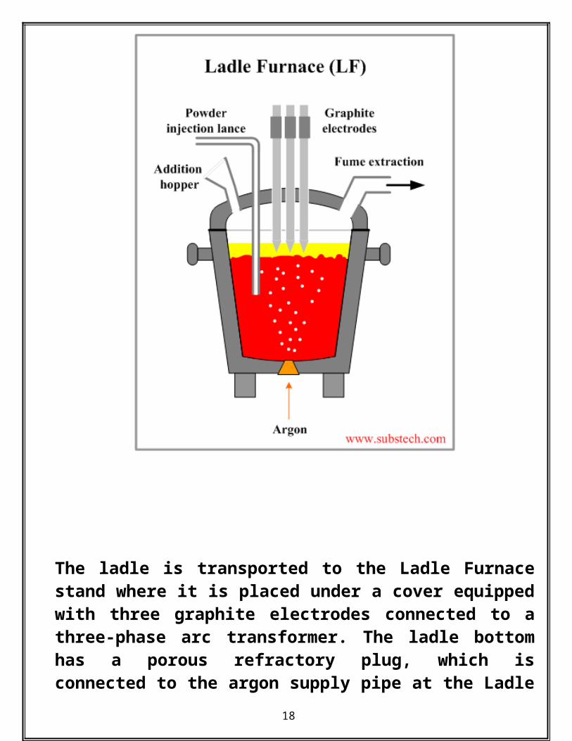
The ladle is transported to the Ladle Furnace stand where it is placed under a cover equipped with three graphite electrodes connected to a three-phase arc transformer. The ladle bottom has a porous refractory plug, which is connected to the argon supply pipe at the Ladle Furnace stand. The LF stand is also equipped with an addition hopper mounted on the cover and a lance for injection of desulphurizing agents. Fumes formed during the operation are extracted through the cover. Molten steel treated in Ladle Furnace is covered by a layer of desulphurizing slag. The graphite electrodes are submerged into the slag, which protects the ladle lining from overheating produced by the electric arcs. The arcs are capable to heat the steel at the rate about 5°F/min (3°C/min).During the treatment process argon is
13
blown through the bottom porous plug providing continuous metal stirring. Stirring results in distribution of heat produced by the arcs, chemical homogenization and desulfurization of the steel by the slag.
Alloying elements and or slag components may be added through the addition hopper. Aluminum in the form of wire is added during heating, as this is a very good killing agent. It readily reacts with the oxygen and makes aluminum oxide and deoxidizes it. Calcium silicate is added at high speed so that vigorous purging takes place. It makes slag to remain in liquidous form.
Schematic Diagram to Show LRF
14
The ladle is transported to the Ladle Furnace stand where it is placed under a cover equipped with three graphite electrodes connected to a three-phase arc transformer. The ladle bottom has a porous refractory plug, which is connected to the argon supply pipe at the Ladle Furnace stand. The LF stand is also equipped with an addition hopper mounted on the cover and a lance for
15

injection of desulphurizing agents. Fumes formed during the operation are extracted through the cover.
Molten steel treated in Ladle Furnace is covered by a layer of desulphurizing slag. The graphite electrodes are submerged into the slag, which protects the ladle lining from overheating produced by the electric arcs. The arcs are capable to heat the steel at the rate about 5°F/min.
During the treatment process argon is blown through the bottom porous plug providing continuous metal stirring. Stirring results in distribution of heat produced by the arcs, chemical homogenization and desulfurization of the steel by the slag. Alloying may be added through the addition hopper. If deep desulfurization is required active desulphurizing agents are injected into the melt through the injection lance or in form of cored wire.
2.2) Salient feature of Ladle refining furnace:-
No. of LRF 3Make SMS DEMAG
16

Capacity 100 T eachTransformer rating 18 MVA
2.3) Importance of LRF:
Its main function is reducing impurities. This zone is usually used to reduce the sulphur presence in the hot metal. Sulphur presence is controlled between 0.2 – 0.4. Its excess presence leads to the hotshortness which increase the difficulty during the hot rolling process. Afterwards from LRF the refined hot metal is passed into degassifier zone to remove the presence of gas.
2.4) This is mainly done by these two processes
i). Vacuum Degasserii). RH- Degasser2.4.i)VACCUM DEGASER
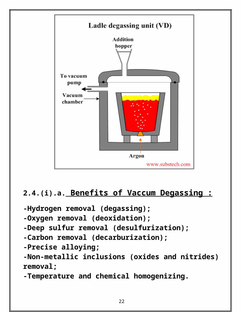
In the Tank Degassing method the ladle with molten steel is placed into a vacuum chamber. The ladle is equipped with a porous refractory plug mounted in the ladle bottom. Through the plug argon is supplied during vacuum treatment. There is an addition hopper with vacuum lock on the chamber cover. The hopper is used for adding alloying elements and or slag components.The reaction inclusions and gaseous nitrogen
[C] + [O] = {CO} starting in the steel under vacuum conditions causes stirring, which is
17
additionally intensified by argon blown through the bottom porous plug. Intensive stirring of the melt and the slag results in deep desulfurization of the steel. Desulphurizing slags possessing high sulphur solubility are used in this process. Argon and CO bubbles also favor the process of floating and removal of nitride.
Schematic Diagram to Vacuum degasser
2.4.(i).a. Benefits of Vaccum Degassing :
18

-Hydrogen removal (degassing);-Oxygen removal (deoxidation);-Deep sulfur removal (desulfurization);-Carbon removal (decarburization);-Precise alloying;-Non-metallic inclusions (oxides and nitrides) removal;-Temperature and chemical homogenizing.
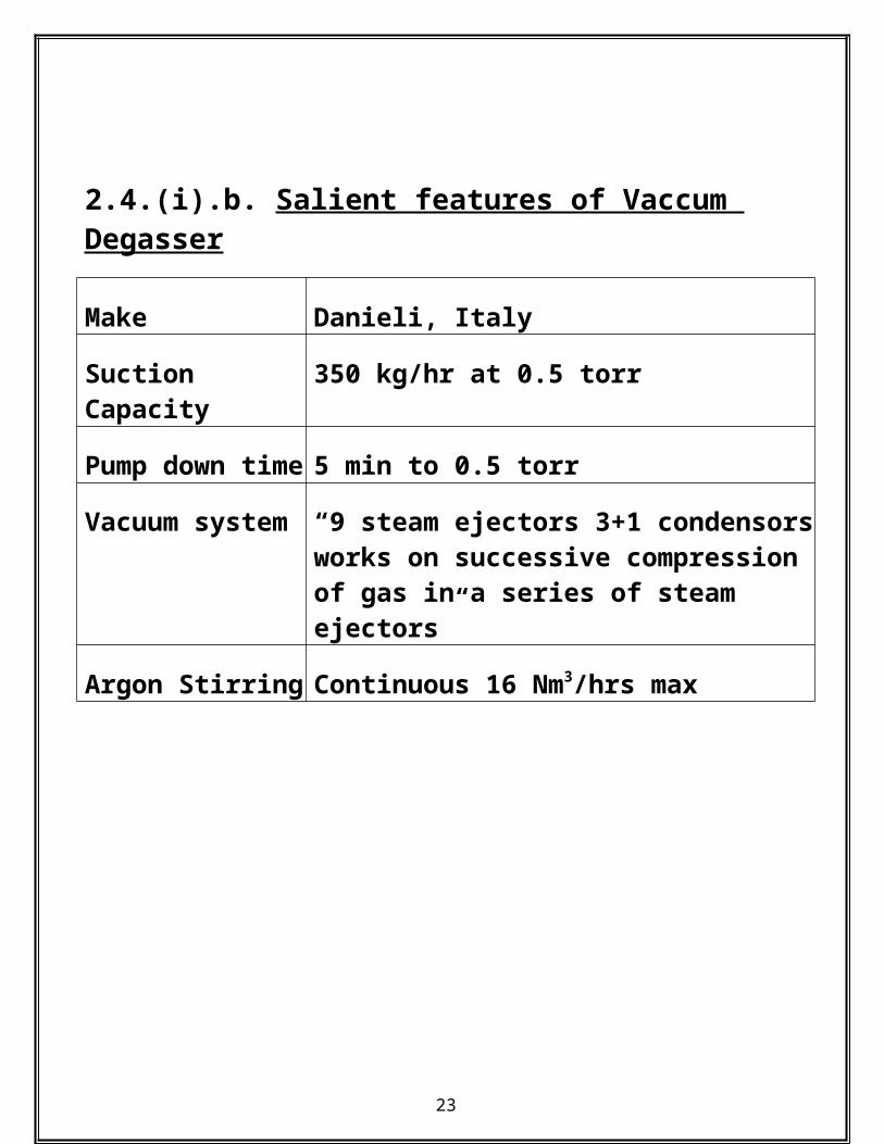
2.4.(i).b. Salient features of Vaccum Degasser
Make Danieli, Italy
Suction Capacity
350 kg/hr at 0.5 torr
Pump down time
5 min to 0.5 torr
Vacuum system“9 steam ejectors 3+1 condensors works on successive compression of gas in a series of steam ejectors”
Argon Stirring Continuous 16 Nm3/hrs max
19

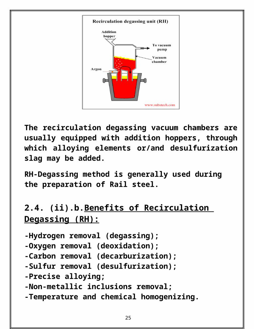
2.4. (ii).a. RH-DEGASSER
RH-Degasser is the degasifying method in which RH stands for name of scientist “Ruhrstahl Hareous” Recirculation degassing unit uses a vacuum chamber having two snorkels connected to the chamber bottom. One of the snorkels is equipped with pipes supplying Argon through its refractory lining.The snorkels of the vacuum chamber are immersed into the ladle with molten steel. Liquid metal fills the chamber to a level determined by the atmospheric pressure (4.2ft/1.3m). Argon bubbles floating up in one of the snorkels (up-leg) force the melt to rise in the snorkel. Through the second snorkel (down-leg) the molten steel flows down back to the ladle producing circulation. The circulation rate may reach 150-200 t/min.
Schematic Diagram to show RH Degasser-
20

The recirculation degassing vacuum chambers are usually equipped with addition hoppers, through which alloying elements or/and desulfurization slag may be added.
RH-Degassing method is generally used during the preparation of Rail steel.
2.4. (ii).b.Benefits of Recirculation Degassing (RH):
-Hydrogen removal (degassing);-Oxygen removal (deoxidation);-Carbon removal (decarburization);-Sulfur removal (desulfurization);-Precise alloying;-Non-metallic inclusions removal;-Temperature and chemical homogenizing.
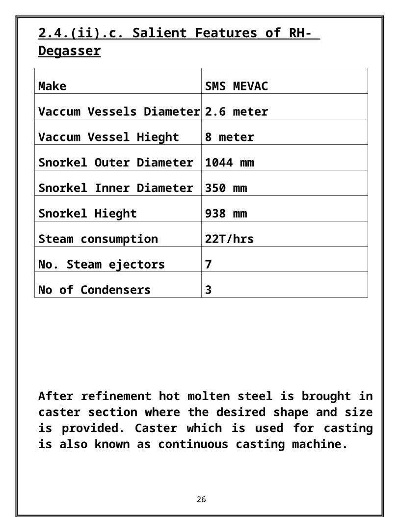
2.4.(ii).c. Salient Features of RH- Degasser
Make SMS MEVAC
21
Vaccum Vessels Diameter
2.6 meter
Vaccum Vessel Hieght 8 meter
Snorkel Outer Diameter 1044 mm
Snorkel Inner Diameter 350 mm
Snorkel Hieght 938 mm
Steam consumption 22T/hrs
No. Steam ejectors 7
No of Condensers 3
After refinement hot molten steel is brought in caster section where the desired shape and size is provided. Caster which is used for casting is also known as continuous casting machine.
3). There are mainly three types caster which is used
i. COMBI CASTER
ii. BILLET CASTER
iii. SLAB CASTER
22
3. (i)COMBI CASTER
3. (i). a. Overview of Combi Caster at JSPL Jindal steel and power limited at Raigarh, cg, has in its SMS 2, a very important and crucial section. This section is mainly responsible for the tonnage production of the bloom, beam blank and round bars. This is none other than the combicaster at JSPL. Positioned near the billet caster, section it acts as a competitor the billet caster for the massive production of above three items. The final product then is either sent to the reheating furnace or to the plate mill or RUBM sections for the preparation of the final products.
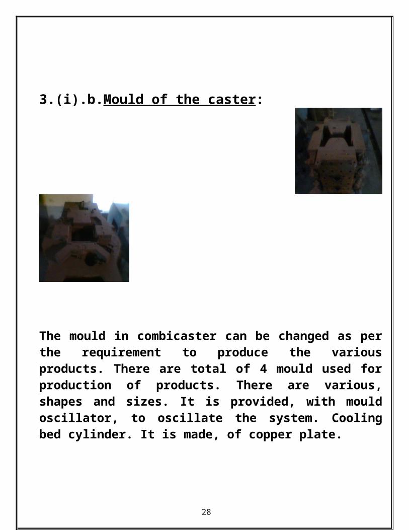
3.(i).b.Mould of the caster:
23

The mould in combicaster can be changed as per the requirement to produce the various products. There are total of 4 mould used for production of products. There are various, shapes and sizes. It is provided, with mould oscillator, to oscillate the system. Cooling bed cylinder. It is made, of copper plate.
Mould oscillator set up
Round mould: 305 mm dia, 255mm dia, 285mm dia .Bloom mould: 250*250mm2, 390*285mm2.
3.(i).c. Segment area:
24
Segment area , view of seg, 01.
The segment area , is yet the mechanical massive part of the combicaster. Unlikethe slab caster, it has atotal of 3 segments, and they are housed inside a large block. Segment 1: first segment after the mould. Has a footroll of 8 rollers, segments has 120 rolls. Back up, has rolls, fixed to it. Each , segment has brackets, 6 rolls on inner sides, 6 rolls on outer side, it is provided with a header spray, which spray water on the bloom, there are 8 spray pipes. There are 3 zones of spray, zone 01, 8 sprays. Zone 02, 15 spray, and zone 03,8 spray in all. Segment 2: second in position after the first segment, it has no footrolls. It has 24 rolls, total of 6 bracket. It has no phalanges, spray zone has 12 nozzles, zone 05 has 12 nozzles. Segment 3: no footrolls, 4 rolls, 1 big piece rolls, to straighten the bloom blank. Spray header 4 no is there is a guide plate.
25
3.(i).d. Use of Gega cutter:
The gega control, cause the correct length of the bloom, blank to be cut. It uses an automatic sensor that , senses the length to be cut and reaches the position to cut the bloom blank using torch and lpg flame. It has an measuring roll, that automatically senses the position to be cut. It has a zero set of 1800 mm. it has 3 motors, to provide the machine drive. One motor conducts the machine drive, another causes the torch drive and the other one causes torch movements up and down. There is a clamping arm that clamps to a position, and sets the length to be cut.
3.(i).e.Conclusion:
The combicaster induction was very useful in knowing the essence of casting and its various parameters, set and used to provide the company
26
its semi finished products in form of bloom, beam blank etc.
Features of Combi Caster:No of strands 4Machine type Combination Caster with
curve mouldSupplier VAIRadius 12000 mmMode of Strengthening
Continuous
Machine Speed Speed range: 0-2.5 m/minRestranding Speed: 3 m/min
Length from meniscus inmould to torch cutter
32.5 meter
Mould Length 800mm Metallurgical Length 20.5 meterDummy Bar system Chain type dummy bar
systemMould level control Co6o with stopper rod
controlOscillation DynaflexCut length 4.5-12 meterType of mould Curved mould with Cu
plates for beam blank and blooms.Copper tube for rounds.
27
3. (ii)Billet Caster
3. (ii).a. Overview of Billet Caster at JSPL
The Billet Caster here at JSPL, Raigarh, is a 6 strand continuous casting machine capable of producing billets of both round and square cross section of various cross section, details of which is given below.
SQUARE(Side in mm)
ROUND(dia in mm)
130 142150 162165 180200 200
220
3. (ii).b.CASTING PROCESS:
The casting process begins with the preparation of the moulds and the tundish. Tundish in the casting area is heated for 1.5 to 3 hrs as hot tundish practice is followed. This is done in the tundish car itself. It is always
28

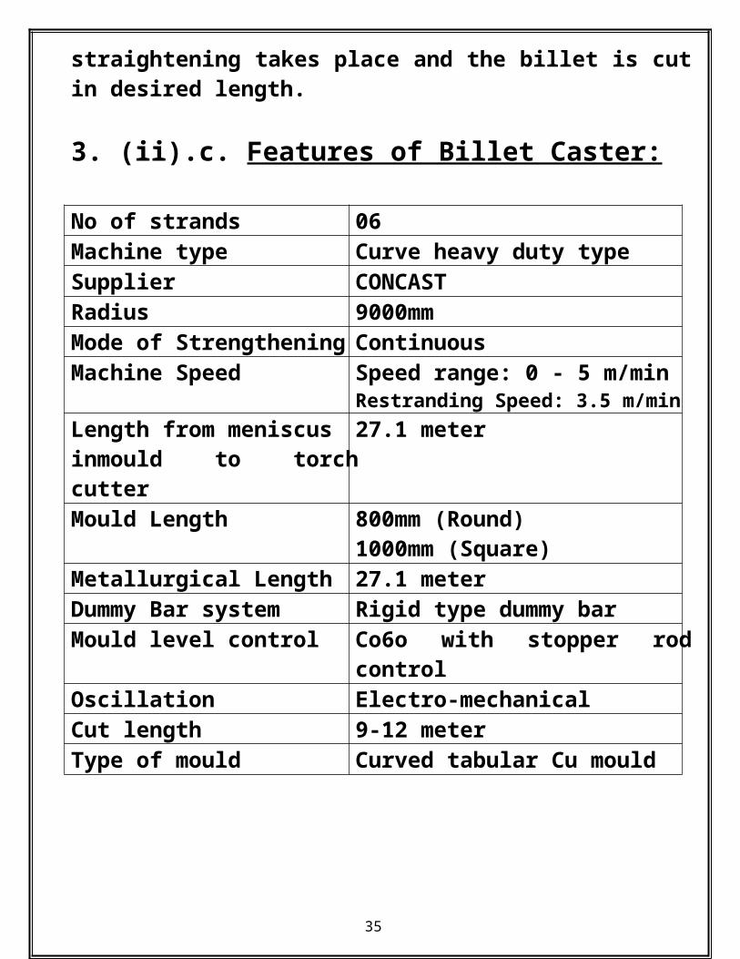
preferred to start heating the tundish then after sometime the SEN; it is because moisture from SEN is removed as tundish gets heated up. The dummy bar is brought in with the help of withdrawal and sealing of dummy bar is done using suitable materials. Then ready to cast conditions are checked for which when fulfilled we proceed forward. The tundish placed in the ladle turret is brought over the tundish. The fitting of argon purge pipe and shroud is fitted. The hydraulically operated slide gate is opened and shroud connected to ensure a proper passage for the steel melt. As the casting is underway casting powder is added to the mould at frequent intervals to avoid the sputtering of metal to outside. The moulded melt passes down the caster while being extensively spray cooled. The withdrawal and straightening takes place and the billet is cut in desired length. 3. (ii).c. Features of Billet Caster:
No of strands 06Machine type Curve heavy duty typeSupplier CONCASTRadius 9000mmMode of Strengthening ContinuousMachine Speed Speed range: 0 - 5 m/min
Restranding Speed: 3.5 m/minLength from meniscus inmould to torch cutter
27.1 meter
Mould Length 800mm (Round)
29
1000mm (Square) Metallurgical Length 27.1 meterDummy Bar system Rigid type dummy barMould level control Co6o with stopper rod
controlOscillation Electro-mechanicalCut length 9-12 meterType of mould Curved tabular Cu mould
3. (iii). Slab caster:3. (iii).a. Overview of Slab caster at JSPL:
Slab caster is an important functional part in any of the steel industry. It is the place where the hot, molten steel is brought with the help of ladle and poured into tundish , which slowly regulates the steel into the mould and provided with the initial support of the dummy bar the required shape and size of the slab is achieved.
The required process flowshet for slab.
30

3. (iii).b. Sections of a slab caster:
These are the major portions of the slab caster unit.
31

Diagram of the continuous caster producing slab.
3. (iii). c. Features of Slab Caster:
32

No of strands 01Machine type Curved mould slab casterSupplier SMS DEMAGRadius 12000 mmMode of Strengthening
Single point
Machine Speed Speed range: 0-2 m/minRestranding Speed: 1.2 m/min
Mould Length 700mm Metallurgical Length 17.3 meterDummy Bar system Chain type dummy bar
systemMould level control Co6o with stopper rod
controlOscillation HydraulicCut length 3.5-9 meterType of mould Curved mould with copper
Mould.
33

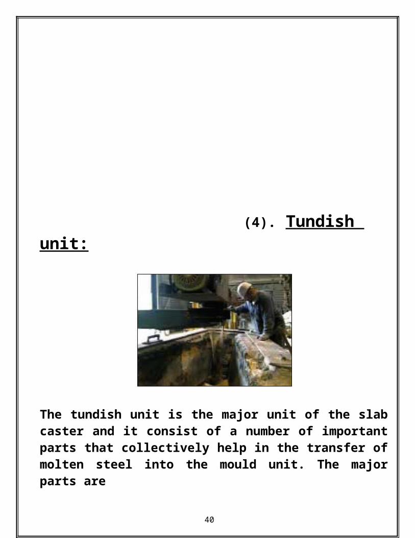
(4). Tundish unit:
The tundish unit is the major unit of the slab caster and it consist of a number of important parts that collectively help in the transfer of molten steel into the mould unit. The major parts are
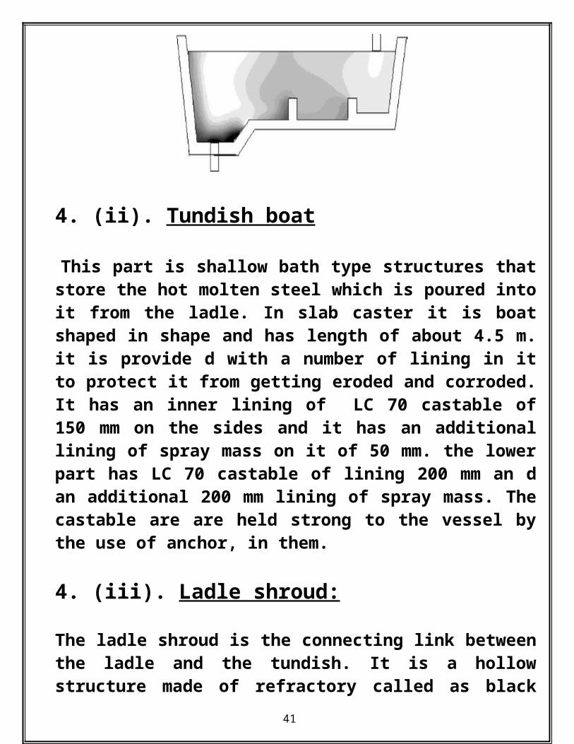
4. (ii). Tundish boat
This part is shallow bath type structures that store the hot molten steel which is poured into it
34
from the ladle. In slab caster it is boat shaped in shape and has length of about 4.5 m. it is provide d with a number of lining in it to protect it from getting eroded and corroded. It has an inner lining of LC 70 castable of 150 mm on the sides and it has an additional lining of spray mass on it of 50 mm. the lower part has LC 70 castable of lining 200 mm an d an additional 200 mm lining of spray mass. The castable are are held strong to the vessel by the use of anchor, in them.
4. (iii). Ladle shroud:
The ladle shroud is the connecting link between the ladle and the tundish. It is a hollow structure made of refractory called as black refractory. It has a length of 126 cm. and it has an upper dia of 19 cm, and inner dia of 13cm, where as the lower portion is 13 cm, and the id is 8 cm. the main function of using shroud is to maintain a continuity among the ladle and tundish, to see that there is no loss of heat when metal is transferred from ladle to tundish, to prevent splashing and spurting of the metal as it falls on the tundish base.
35

Ladle to tundish connection.
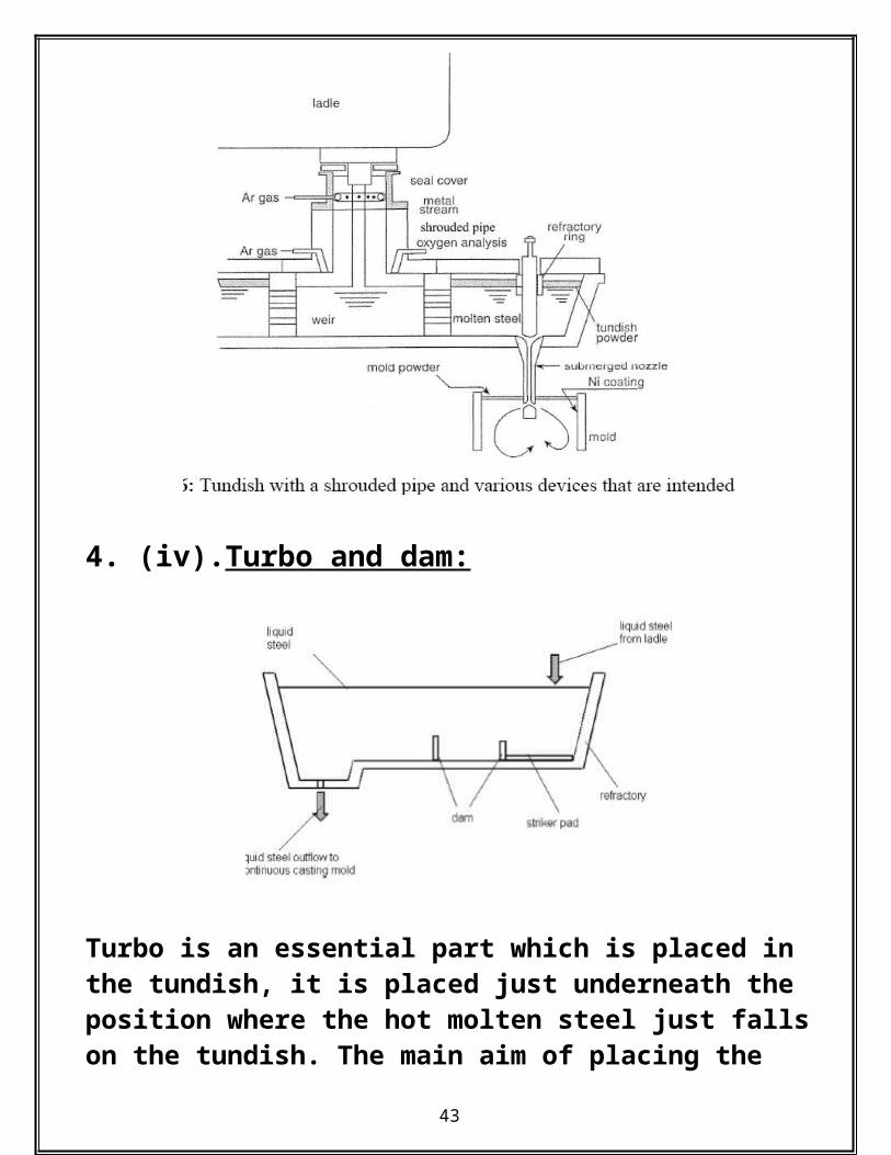
4. (iv).Turbo and dam:
36

Turbo is an essential part which is placed in the tundish, it is placed just underneath the position where the hot molten steel just falls on the tundish. The main aim of placing the turbo is to lessen the impact and maintain the ferrostatic pressure between the tundish and the ladle. The turbo absorbs and nullifies the high pressure with which the molten steel falls on it,. it is made up of alumina refractory.
Turbo diagram.
37

The Dam which comes next to it is also an essential part that helps to maintain the free flowing hot metal away from contact with the solidified part of the molten metal. The dam also helps in maintaining the ferrostatic pressure.
4. (v).Sub entry nozzle (SEN): The sub entry nozzle is the channel through which the molten steel flows into the mould. It is provided with 2 ports, diametrically opposite to each other. The port measures 80mm * 65 mm. The length of the SEN is 1205 mm, in length. it has an diameter of 60 mm. it pours the metal into the mould. It is made of alumina graphite, refractory and is covered from outer side by glass wool. SEN is generally preheated before start of casting at 700 to 800 degree Celsius for one and half hour.
4. (vi). Stopper:
38

The stopper is operated through the help of a hydraulic system, and it performs the work of regulating the amount of flow of molten metal into the mould. It has a length of 1495 mm.
4. (vii). The Role of Tundish in the Continuous Casting Process:
To transfer finished steel melt from a ladle to the mold in a continuous casting machine, an intermediate vessel, called a tundish, is used. A tundish, is a rectangular big-end-up, refractory-lined vessel, which may have a refractory-lined lid on the top. The tundish bottom has one or more nozzle port with slidegate or stopper rod for controlling the metal flow. The vessel is often divided into two sections: an inlet section, which generally has a Tundish with a shrouded pipe and
39
various devices that are intended to minimize contamination by and maximize flotation of macro inclusion pour box and where steel melt is fed from the ladle; and an outlet section from which melt is fed into the mold. Various flow control devices, such as dams, weirs, baffles with holes, may be arranged along the length of the tundish.
DIFFERENT SEMI PRODUCTS OF SMS-II
40
41

5. SAFETY ASPECTS
1. We should always wear safety helmet, safety shoes etc.
2. Don’t wear loose clothes in the industry.
3. Don’t move here and there without permission and in the restricted areas.
4. Always use gas mask in dusty and poisonous gas regions.
5. Use ear plugs while moving towards noisy region.
6. Don’t touch any panels in control room.
42
6.CONCLUSION1. The main part of steel melting shop is electric arc furnace, in which 52% of hot metal and 48% of DRI get charged.
2. Steel melter must have knowledge about the refractory lining. In the electric arc furnace the nature of slag is acidic, that is why basic refractory (magnesite) is used.
3. When the slag becomes foamy than the oxygen supply will set. This is primary steel making process where decarburization and dephosphorization.
4. Ladle refining furnace is secondary steel making process.Its main function is to reduce the inclusion and impurities which are present in the molten steel.
5. Desulphurization process is basically carried out in LRF. And for this process basicity of 2 is maintained.
6. All the caster consisits of mould which is made up of 99.9 % copper and 0.1 % of silver.
7. Casting powder is basic in nature which works as a lubricant.
8. Now a day in the caster high pitch roller are used to prevent from bulging.
43

9. The coordination between the EAF, LRF and Caster must be maintained.
7). REFERANCE:
1. Materials received from SMS-II office like Process flow chart, SOP etc.2. www.google.com/ Steel melting shop3. www.wikipedia.com/ steel melting process4. By discussion with the Sr. Managers of SMS-II
44