research memorandum - digital library/67531/metadc58041/m... · · 2018-04-24research memorandum...
TRANSCRIPT
"
RESEARCH MEMORANDUM
AERODYNAMIC CHARACTERISTICS 0F.A 45' SWEPT-BACK WING
WITITASPECT RATIO OF 3.5 AND NACA 2S-50(05) -50f05)
AIRFOIL SECTIONS
Anthony J. Proterra
Laggley Memorial Aeronautical Laboratory Langley Field, Va.
CLASSIFICATION CANCEL "
.. . c
NATIONAL ADVISORY COMMITTEE FOR AERONAUTICS.

E R R A T U M - NACA RM NO. ~ 7 ~ 1 1
i
! I
i
UNCLASSIFIED NATIONAL ADVISORY CCMMInEE FCLR AERONAUTICS
"
BY ethony J. Froterra
SUMMARY
The results of an investigation to deternine tho aerodynamic characteristics a t high Reynolds numbere and low Mach IlIHnbers of a 45' swept-back wing with aspect ratio -3 .5, tqer ratio of 0.5 and circular-arc seations are premnted i n , this report I Scale effects were investi@ted at Reynolds nunibore ranging from 2.1 X 10⁶ to 8.0 X 10⁶; the effects of yaw were ~nvestigated at a Reynolds number of k.1 x 106.
The results indicate that the wing has goor characterfstics from low-speed considerations. The w i n g kaa a maximwn lift
of attack. Tho longitudinal stability is neutral up to a l i f t coefficient of approximtely O..3 and increases above this value to a lift coefficient of' approxbately 0.5. Between 8 lift coefficient of 0.5 and maximum lift cosfficient C h the wing ie longitudinally unetable but at C h the wing has a diving tendency. The effeat5ve dihedral is positive. up to a lift coefficient of 0.45 but is negative above this value. The w i n g has neutral directional stability up to a lift coefficient of 0.43 and is directionally unstable at h i e e r ' l i f -b ooefficients The lift, drag, and pitching-moment coefficients are almost unaffected by variations in Reynolds number.
- coefficient of approximately 0.87 ana has high drag at high angles
INTRODUCTION
L
The proposed w e of swept and, low-aspect-ratio wing plan f o r m . .
and blconvex profiles to minimize compressibility effects at transonic
scale aerodynamic ChWaCt~ri6tiCs of these w i n g 6 at low Mach numbers. I arid supersonic speeds has omphasized the need for data on t h e fa-

0 -
A &uQ- ia, therefore, betng made In t h o Langley full-scale tunnel of the lownspeed characteristics -of win@ havjlla lopercent-thick circular-arc supersonic a i r foi l8 and various hi&-l i f t devices. fls a pert of this 13tud.y an invepltigation ha8 been made with a 45' swopt- beck wing of aspect r a t i o 3.5 and taper ra t io 0.5.
The present paper premnta the scale effect on the longttudinal aerodynamdc characteristics, the aerodynamic characteristics i n yaw, and the tuft studies f o r Oo and 3.7O yaw. ?%e resul ts of the effect of leadks-ed&e and tyal l inpedp- flaps on the aerodynamic character- istics of the wing w i l l be preeonted in later reporta.
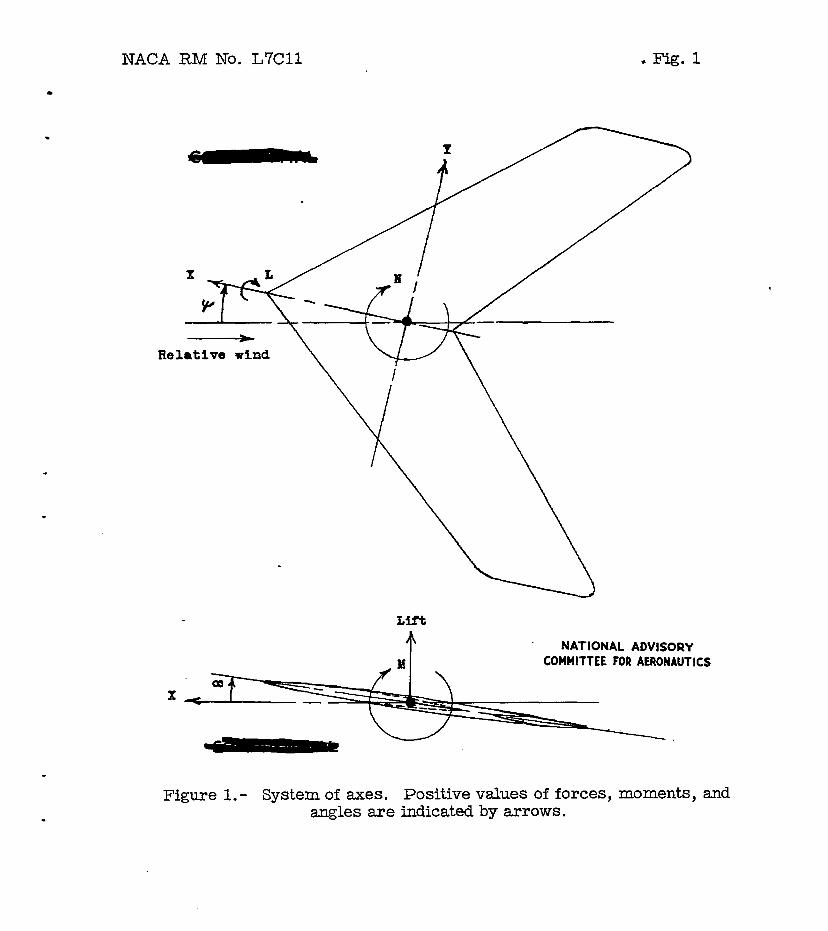
The data are referred t o the atability axos, which a re a eystem of ax8s in which the Z-axis is in the plane of syrmnetrg and perpen- dicular to t h e relative wind, the. X-axis is i n the plane of S-IZY and perpendicaar Lo the z-axis, and. athe Y-axis is porpendicuhr t o the plane of symnetry . The o r i d n w a ~ loca-ted a t guaryfie1- chord of, mean aarodynaic chord. The poeitive dlrect iom of forces,,,of. . . moments, of dieplacemente of the model are #van in figure 1.
. . .
. . .
I . '
, . . . .
Y l a t e ra l force, pounds . . .
RACA RM No. L7CU
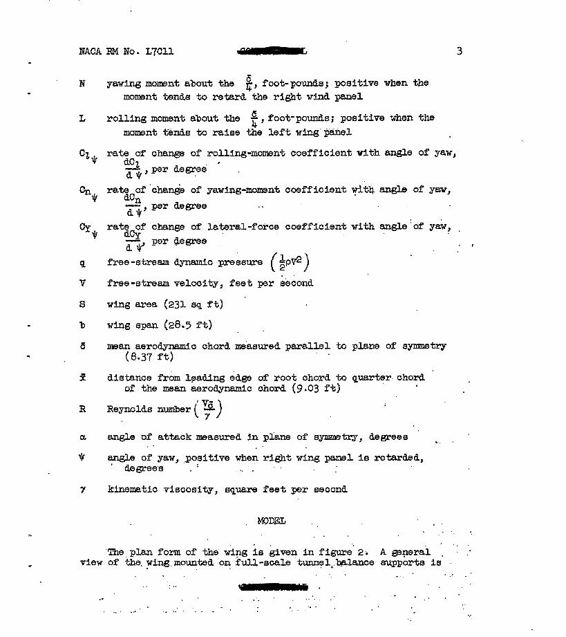
N gawirig mmnt about the 8, foot- pounds; positive when the - moment tends to retard the r i g h t wind pmel
L ro l l i ng moment abaut the a foot-pounds; positive when the 4 j moment t b d s to raise the l e f t win@;- panel
3
E distance f r o m leading edge of root chord to buarter- chord '
€4 Reynolds nuniber (F) o f the mean aerodynamic chord (9.03 f t )
a angle of attack msasured i n phm of symmta~ , degrees
f angle of yaw, positive when right wing panel is ratarded,
. . ' degrees . . .. -
y kinematic viscositr , square fee t per second
"
4 - MACA RM NO. ~ 7 ~ 1 1
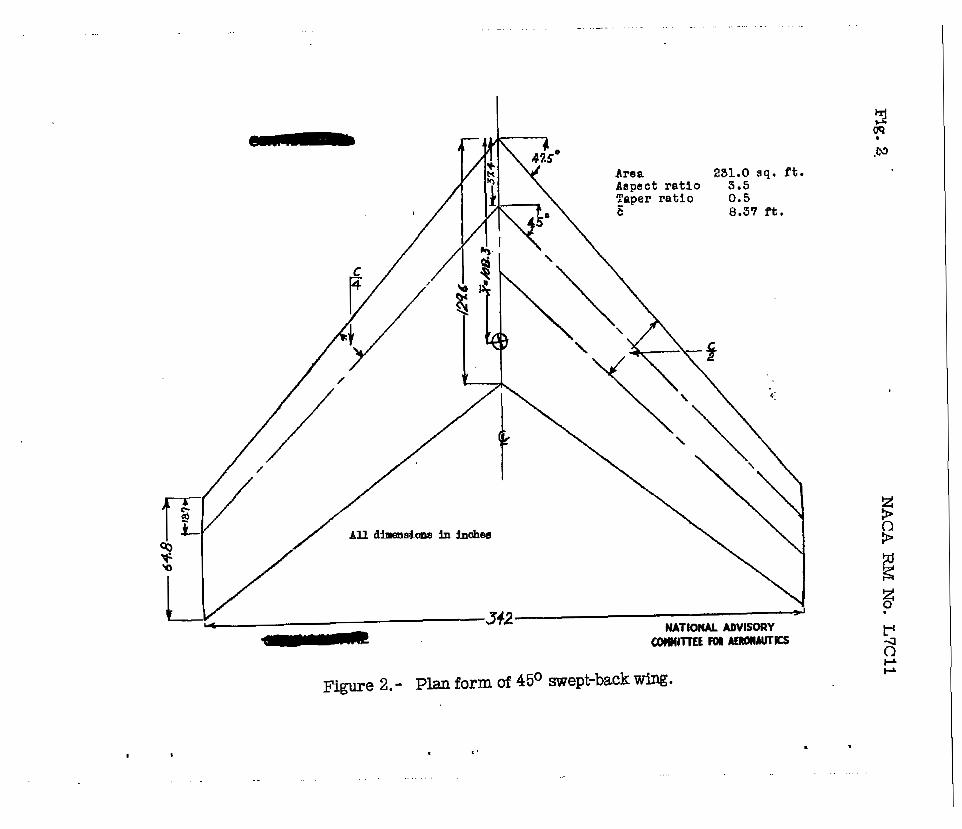
shown in fi- 3 The WFng kas an an@e of sweep of 45* at the quarter-chord line. The airfoil eections perpendicular to the 50-percent chord l i ne are circ@w-arc sectione and have a maximum t h i chese of 10 percent a t the W-percent chord. The mdel has an aepect r a t lo of 3.5 and a taper r a t lu of 0.5 with the wing t i p s sl ight ly rounded. The has no geometric dihedral or twiet.
The wing vas Qonatructed of l b - inch aluminum sheet reinforced by steel channel spars. The wtng surfaces wore about the equivalent in roughness t o canvantianal thin dural sheet cmstruo.tion with dimpled skin and unfilled flush rivete. The viw construction was extremely rigid and it is not bslievod that deflections of any appreciable magnitude occwed during the teats .
The Jet-boundary ekPect6, the blocking effects, the stream ,
alinement, and. the taree cawed by the wins dupport s t ru t s m6e '
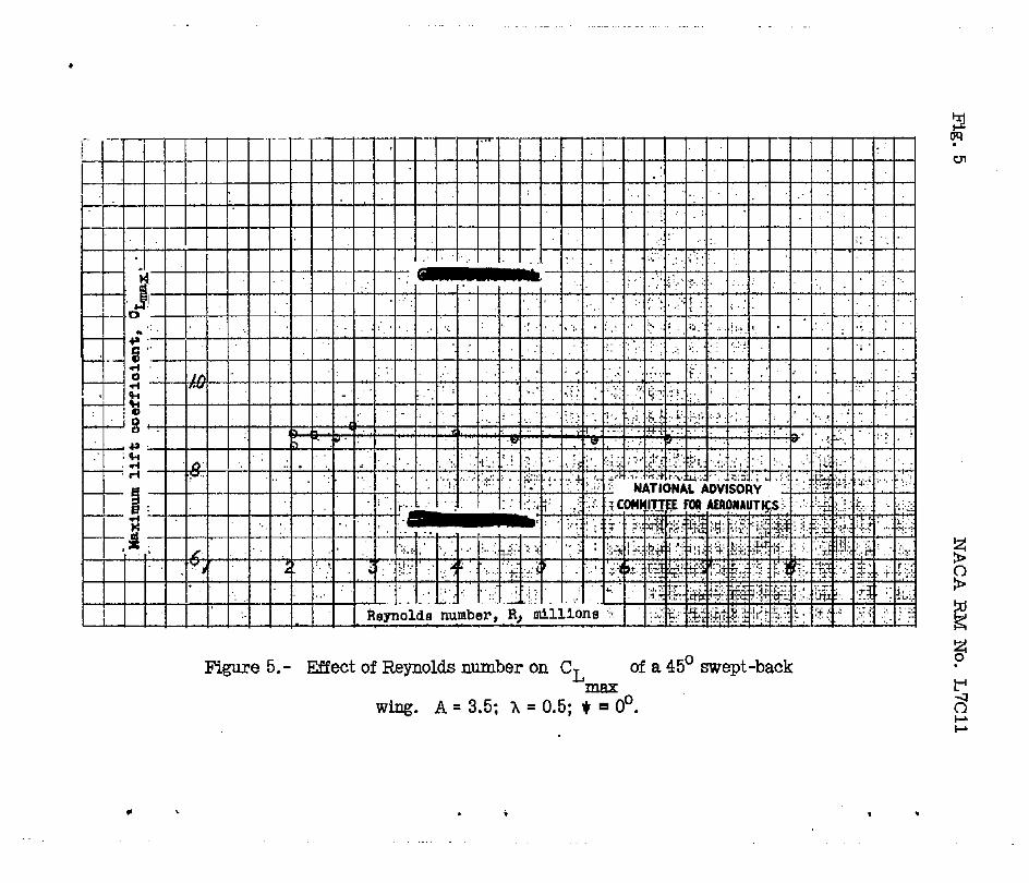
calculated for t h e zero yaw condition and were used for correcting the angles of attack, the longitudinal-force, %he W f t , and the . pitching-nwnt coefficients of t he d a t a &ven'her6in at all . angles of yaw. No corrections were applied t o .-the yawhg.and rolling-mament coefficients Due t o 'the .sU&t -+hriatiloh bf the tunnel apeed with an- of attack the results i n ' f i w e k a& figure 5 are presented for ReynoldEl numbers a t zero Uf't and ,a t max$m~~.U-ft, reepectively. ' . . . , , . . *
Oor convenience the discussion is presented in three parts. The first part deals with the scale effect oa the aerodynamic - ._ I . . . , . . . ..,a: ., .:. 8 . .- . . . " . . . , . . . . .
I . , r . . :. r .. . I . , '
, . . . . . . . .

Scale Effect OR the Aerodynamic Characteristios at Zero Yaw I "
The ef fec t of Reynolaa mmb8r on th8 Eterodymmic charwter i s t ics of the w i n g is shown in figure 4. The lif %-curve peaks, the drag, and the pitching-moment coefficients were almost unaffected by variations i n Reynolds number. The pitching-moment ourvea (fig. 4(c)t .micate that the wing w i l l be neutrally stable up to a lift '
coefficient of approximately 0.3 and above this value to a l i f t coefficient of approxbxatelg 0.5 the Longitudinal s t ab i l i t y of the wlng increased. The increa-d. stabflity between l i f t coefficients of OI.3 and 0.5 f o r the wing i s at&$buted to an outward sh i f t in the spanwise location of the center of pressure an each wing. panel. . From the l l f t coefficient of 0.5 to about the piwhing- moment curve'a indi'oa.ts a rapid increase in pftohing momnt in the unatable direction. This increase is attributed to inward shi f t in the spanwise location of the center .of pressure on each w i n g panel. Tuft observation (fig. 8 ( ~ ) ) indicates *at &8 the lift coefficient . is increased from approximately 0.5 t o sbout k, the stall mves progressively toward the center sections of the wing. The pitching- momnt curves also indicate that the wing at a b u t CrmalE w i l l have a diving tendency. .-w aving tendency it about would indicate a loss in the load at the root section. Tuft observation (f ig . 8(a)) a t th i s attitude indicates t h a t the air flow beoomse spanwise an& rough near the center portions of the' wing. At angles . of attack up t o approximately 80 the elope of the lift curve I increased w i t h an@e of attack. Abom th i s value the slope deoreaeed w i t h angle of attack. The drag of the wing is considered fairly high at hi& angles of attack when compared xith'round-leading-edge wags.
6
The aerodynamic Cha.raCteriEtiC6 of the w i n g over a rt5nge of yaw asgle at severe a@es of attack are presented in f fgure 6 . The lateral s tab i l i ty pasametere Cz Jr' Cnv a Cy. Of the w3ng '
are plotted in figure 7 as a function of lift ooef icient. The slopes of Cz Jo Cne a& CyQ were taken from the curves simtlar to those of figure 6(a) a t 00 em- of yaw and are therefore f '
appropriate t o the v a l e s of l z f t coefficient f o r -00 yaw,. A t -I . . ., -
lift coefficients up to 0.4 ' the rolling m w n t increased nearly , . 1inePtrl.y with yaw in the airection to raise &e forward wiq pass1 ... . Above this value the rol l ing maments -ohan@ imgularly In ,the dlrectian t o lower the forward wing panel. ._ This vwiafsion of rolling mmmt * '
with yaw indicates that the forward w i n g panel; etalled first. Tuff . . . . observations (fig. 8(b)) also indicate the. sarne resul.t3s.
. I
. .
" . . . ..
A t a I L f t coefficient up to 0,.3 ;&,yaw+g momsst of the *ng changeavery little ..y& %,h yaw. Abow, *,Is qalue tlp .yaw- rbwnts change fairJy sLar2.y and imgu&arly , w i t h yaw.
The results in figure 8.
A t zero yaw
. .
Tuft studies of the Wt studies fo r Oo
and low angles of attack the air flow over tho wing swept-back wing having conventional a i r f o i l
I - e . , .
. . I . . , . . . .
. *
lche 'results obtained with t h i s wing are sommd~at cmtradic.t;ory t.0 those that have been ob%ained. with swept-back vin@ havine con- v e n t i m l a9 r fo i l eectLons. It is, therefore> desirable t o take note of same of the flow phenmena tha t produce these rerjulte, especially since they are.beUeved to be chay.acteristic of hi&lg swept-baok win- havlng a M o i l Boctfons w i t h s h a q leading €dg€tB= A difference between the flow aver win@ of thie type and TKLWS. having cmvantfaaal a i r fo i l eections with round leading edges is t o be expected inasmuch as the flow over the basic airfoil aectiollls themselves ia also g a t e different. Consider first the f l a w over tke bas lc a i r fo i l in two dimensions. The sharp-leading-oQe & ? f o i l is characterized by 8 very early separation a t the leading edge and the f o m t i o n of a so-.czalled bubble of eeparation, aft of which the flow reeatabliahes itsew and ccmtinues in a more o r b s a noma1 fashion; whereas, a canventional section nharacterized by ~ ~ 2 , - zrr*.+r+ an i n i t i a l separation OGCUTB aZ; a much hi q an& of aebck and --:kc 6-7 f,@ther a f t on t h e airfoil surface.
F :S,. . ..
,:>I When the sharp-leading-edge wing is swept back, the fl& t r i e s t o separate a t t h e 1oa-g edae at a low arise of attack (in the
ease of this wing about > or a t a '@ ' 'of' about 0.3) On account
of the relief i n t h e adveme pressure gradient t ha t results from high sweepback, however, the a i r erhply flows spanwise a t the leading edge I These effects are FPdica?ed fn the tuft surveys of figure 8(a) The SpanTkise flow-at t h e lea- edge C~~t tP ibUk8S m e a t l y toward the early stal l ing of the t i p , which stalle first a t the leading edae due fo the ccaabined effects of the spanwise flow a& of the
- .- .-
lo 2
8 MACA RM No. L7CU.
eharp Leet- e d p . On a~mpt-back Hfnga with conventional atrf'oil Bectimm, by aontresti the s t a l l mdinar i ly ,has been observed t o s.tayyG a t t h e t ra i l ing e&ze of the t i2 because of outward floTt Of the boundary layer on the af ter portiona of the wi~~g.
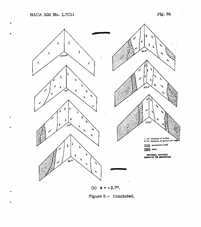
When a swept wing sidsslips, the effect 9s f3iml3sr t o that which t70uld be created by decreasing t h e meep of .the I?adin@; Wfng and incr4iasing the sweep of' the t r a i l i ng T K I ~ . Contrary to the resulte obtsined win! wlslga of conventional airfoil 8ection8, d e c r e w l q t he sweep of the biconvex win6 does not alleviate the s.t;all EF'reciably, and Ln f ac t in ~ o m e stieep ranges may, as in thin cam, even a m a n t e it. LikewiEe, i n C r e a f 3 i w the sweep of the biconvex wing may improve the flow conditiana by a flow meohnim sMhr to the large vortex observed an tho DM-1 glider a f t m the sharp leading eQes were added (ref eronce 3) The generally low effective dihedral -of this wing and the early change f r o m positive t o negt ive ef'fec.t;ive dihedral then appears t o reeult from t h e combined effects of' these chanms In .the flow due to the eideslip anti the early tip stall., The tuft surveys of f i g r e 8 show these effects qui39 clearly. Although hi@'effective dihedral hat3 been m e of the moet seriosw problem ccmfrontine; the desimer attempting t o me swept-back w i n g s I the low effective dihedral cif this wing is by no meane cansidered a soLution to'the problem, because it would probably be .almost impossible to maintain adequate l a t e ra l control by conventional methods af te r the tlp had begun to stall and becawe of the longitudinal tmta'kiUty eqmriencsd a t moderate and hi& a-s of attaak. These problems do npt appear to be unsolvable, but fur ther experimental inverstigation and 13Zud.y of t h e fundamental-flow phenomena wi1L be roqwired before they CEl'n be successf ull;g overcone
S U M M A R Y O F ~ S
. The resalts of force tests of a 45' swe&-back wing having biconvex airfofl sec.t;ions Zn the Langley full-scale tunnel are summarized 8s follows:
1. From lofurrjpeed considerations, the WLng has poor character- i e t fcs &ich a m primarily due to .ear ly tip stall in^.
2 The max3m8n lift coefficient obtained far the is 0
3; 'me ~ i n c is neu t raw stable up to a let coefficient .of approxbately 0,3 and abo& this value .to a lift coefficient of approxWBtel.y.0.!3 the lon@tudinal stability of the ~ d n ; ~ increases,

HACA RM No. L7CU "-m 9
4. The ving has hi& drag at high an@es. of attack.
7. The l i f t , the drag and the pttchinpnmuent CoefficionfiB are a b e t unaffected by variations in Reynolds number
1. Sweberg, Harold 3. and Lange, R a y E. : Summary of Available Data Relating to Reynolds Nmber X f a c t s on the Maximum L i f t Coefficients of Swept-Back W i n g s . NACA RM Xo. ~6120a, 1946
2, Letko, William, and Gaodmsn, Alex: Preliminary Wind-Tmnel Invosti@tion at Lowspeed of Stabi l i ty and Control Character- i s t f c s of Swept-Back Winw. WACA Tm No. l.046, 1946.
3 Wihon, Herbert A. , Jr . , ana Lcnrell, 3. Calvin: Full-Scale Inveetigation of the Mmimum Lift and Flow Characteristics of an Airplane Having A rox3mteI.y 2ria-r Plan Fam. NACA E4 No L&20, 1 9 8
NACA RM No. L7Cll s Fig. 1
. Y /-
- NATIONAL ADVISORY COMMITTEE FOR AERONAUTICS
x, - Figure 1.- System of axes. Positive values of forces, moments, and
angles are indicated by arrows.
. . . . . . . . . . . . . - . . . . . . . . . . . . . . . . . -
. . . . . . . .
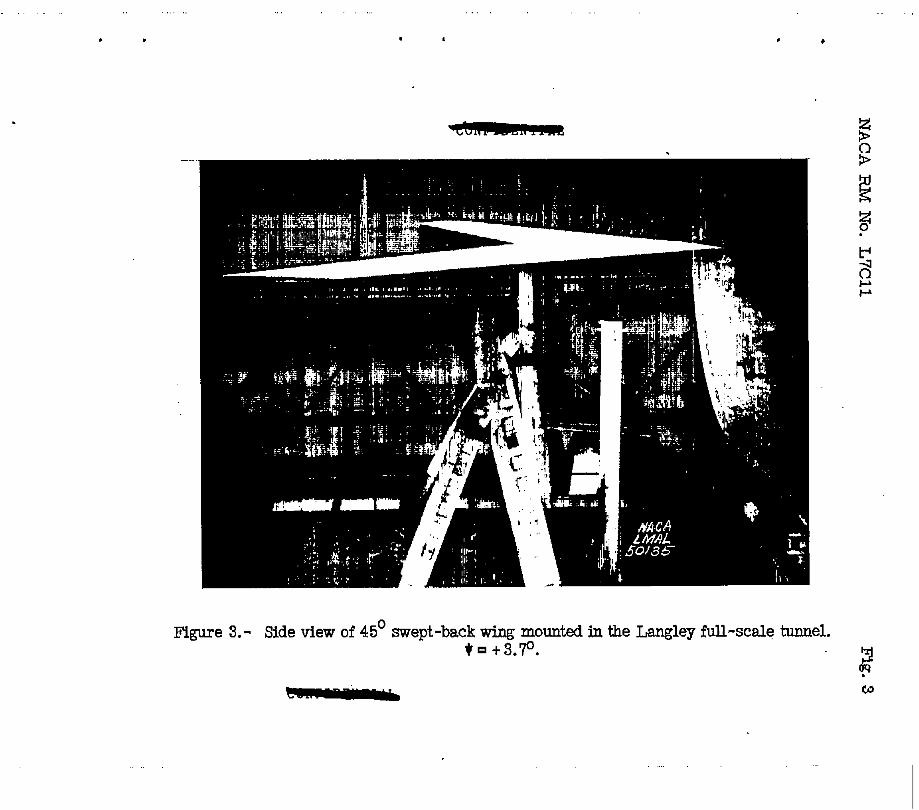
Figure 3.- Side view of 45' swept-back wing mounted in the Langley full-scale tunnel. t t3.70. . 3
c? - 0
.. .. .

. . . .. . .
.
.
(a) CL versus a.
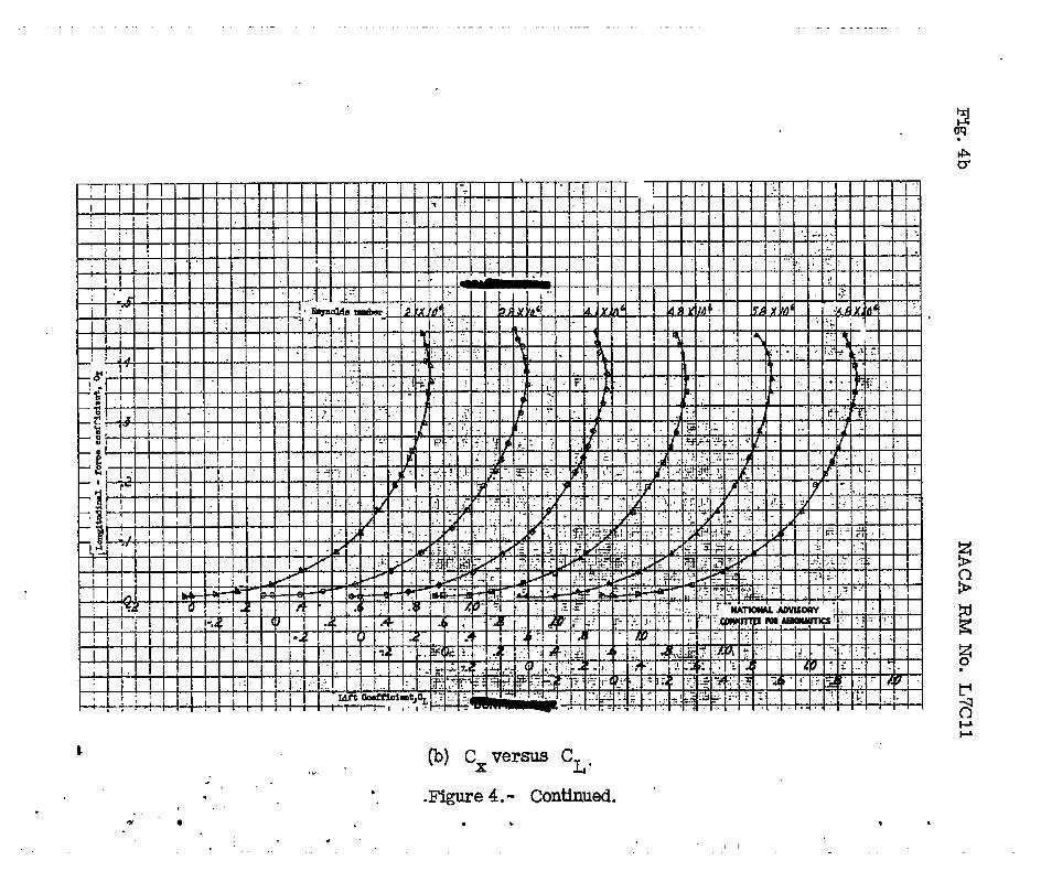
Flgure 4.- Effect of R e p o l d s number on lift, drag, and pitching-moment coefficients of a 45' swept-back wing. A = 3.5; A = 0.5; = 00.
- . . . . . . - . . . . . . . . . . . . . . . . . . .- . . . . . . .
c , ,..
“gure 4.- Continued. *
. I
. . .. ... . ’ , I . . . .

MACA RM No. L 7 C l l Fig. 4c
(c) C, versus CL . Figure 4. - Concluded.
. . . . . . . . . . . . . . . - . . . . . . . . .- . . . . . . . . , . . . . . .
Figure 5.- Effect of Reynolds number on CL of a 45' swept-back max
wing. A = 3.5; h = 0.5; $ 0'.
c
. . .

NACA RM No. L7Cll Fig. 6a
. *
Figure 6. - Variation with angle of yaw of the aerodynamic characteristics of a 45' swept-back wing. A = 3.5; A = 0.5; R = 4.10 x IO6.
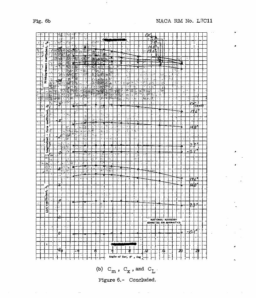
Fig. 6b NACA RM No. L7Cll
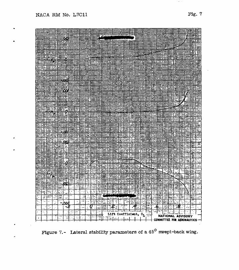
NACA RM No. L7C11 Fig. 7
*

Fig. 8a NACA RM No. L7Cll
(a) + = 00
Figure 8.- Tuft studies for a 45O swept-back wing. R = 4.10 x lo6.
" .
NACA RNL No. L7Cl l Fig. 8b
(b) * = +3.70.
Figure 8. - Concluded.
"
. . . .