reusable case transformation rule specification · reusable case transformation rule...
TRANSCRIPT

Reusable Case Transformation RuleSpecification
Deliverable D3.3, version 1.0, 31.07.2007

IST-2006-033596ReDSeeDSRequirements DrivenSoftware Development Systemwww.redseeds.eu
Infovide-Matrix S.A., Poland
Warsaw University of Technology, Poland
Hamburger Informatik Technologie Center e.V., Germany
University of Koblenz-Landau, Germany
University of Latvia, Latvia
Vienna University of Technology, Austria
Fraunhofer IESE, Germany
Algoritmu sistemos, UAB, Lithuania
Cybersoft IT Ltd., Turkey
PRO DV Software AG, Germany
Heriot-Watt University, United Kingdom
Reusable Case Transformation Rule Specification
Workpackage WP3Task T3.3Document number D3.3Document type DeliverableTitle Reusable Case Transformation Rule SpecificationSubtitleAuthor(s) Audris Kalnins, Elina Kalnina, Edgars Celms, Agris Sostaks,
Hannes Schwarz, Albert Ambroziewicz, Jacek Bojarski, WiktorNowakowski, Tomasz Straszak, Sevan Kavaldjian, Jürgen Falb
Internal Reviewer(s) John Paul Brogan, Albert Ambroziewicz, Jacek Bojarski, WiktorNowakowski, Tomasz Straszak, Hermann Kaindl, Daniel Bildhauer,Hannes Schwarz, Kizito Ssamula Mukasa
Internal Acceptance Project BoardLocation https://svn.redseeds.eu/svn/redseeds/1_DeliverablesSpace/WP3_Re-
usable-case_specification_language/D3.3/ReDSeeDS_D3.3_Re-usable_Case_Transformation_Rule_Specification.pdf
Version 1.0Status FinalDistribution Public
The information in this document is provided as is and no guarantee or warranty is given that the information is fitfor any particular purpose. The user thereof uses the information at its sole risk and liability.
31.07.2007

Reusable Case Transformation Rule Specification – D3.3History of changes
ver. 1.031.07.2007
History of changes
Date Ver. Author(s) Change description06.06.2007 0.01 Audris Kalnins Proposition of ToC
03.07.2007 0.02 Audris Kalnins Changed structure of chapter Providing
models to be transformed
16.07.2007 0.03 Audris Kalnins Added initial content for chapter 4
16.07.2007 0.04 Audris Kalnins Added initial content for chapters 2 and 5
17.07.2007 0.05 Hannes Schwarz Added content for parts of section 5.2
18.07.2007 0.06 The UL team Added content for 2.2, 2.3, 5.2.2
18.07.2007 0.07 Hannes Schwarz Added content for section 5.4
20.07.2007 0.08 The WUT team Added initial content for sections 3.1, 3.2and 3.4
25.07.2007 0.09 The UL team Added MOLA procedures for 4.2
26.07.2007 0.10 The TUW team Added initial content for section 3.3
27.07.2007 0.11 The WUT team Added content for sections 3.1, 3.2 and 3.4
27.07.2007 0.12 John Paul Brogan HWU Conducted document language check anddocument update.
30.07.2007 0.13 The UL team Added MOLA procedures for chapter 4.4
31.07.2007 0.14 Audris Kalnins Added Conclusion
31.07.2007 0.15 TUW team Added content for section 4.3
31.07.2007 0.16 John Paul Brogan HWU Conducted document language check anddocument update.
31.07.2007 0.17 TUW team Minor changes to section 4.3.
IST-2006-033596 ReDSeeDS: Requirements Driven Software Development System page III

Reusable Case Transformation Rule Specification – D3.3Summary
ver. 1.031.07.2007
Summary
This deliverable has a relatively narrow focus on using model transformations for building asoftware case in ReDSeeDS. These software cases are assumed to be built according to theprinciples of model-driven software development. According to these principles, several modelsare built one after another as artefacts of this software case. This building should be performedaccording to a well defined design methodology, of which we currently are interested only as aset of precisely defined rules, what model elements should be used at which artefacts, what arethe naming and structuring rules, what are the desired dependencies between the artefacts andsimilar issues. It should be specially noted that the starting point of a software case is also awell defined artefact - it is the requirements model in RSL.
Model-driven software development includes as one of the basic principles the use of automatictransformations between design steps whenever this is possible. Thus only the initial version ofthe next model is obtained, which is then extended manually.
The above mentioned facts on software case development in ReDSeeDS enables the transfor-mations there to have a significantly greater role than in many standard MDSD applications.In many cases the use of automated transformations can be a critical enabler for building asoftware case according to a strictly defined design methodology in ReDSeeDS.
According to previous deliverables, the SCL includes a special language for defining such trans-formations - the model transformation language MOLA.
This deliverable illustrates a consistent use of model transformations on an example designmethodology, which is based on a 4-layer architecture. For transitions from requirements toarchitecture model and from architecture to design model initially natural informal transforma-tion rules are provided. Then these rules are implemented in the model transformation languageMOLA. For the chosen example methodology, the part of the next model generated by trans-formations can be especially large. Finally, it is briefly discussed, what is necessary to integrate
IST-2006-033596 ReDSeeDS: Requirements Driven Software Development System page IV

Reusable Case Transformation Rule Specification – D3.3Summary
ver. 1.031.07.2007
the model transformations with other tools and support features for software case development.The full solution of these technology issues goes to Workpackage 5.
It should be noted, that transformations developed in this deliverable are not specific to onesoftware case, but to any case built according to the selected example methodology.
IST-2006-033596 ReDSeeDS: Requirements Driven Software Development System page V

Reusable Case Transformation Rule Specification – D3.3Table of contents
ver. 1.031.07.2007
Table of contents
History of changes III
Summary IV
Table of contents VI
List of figures VIII
1 Scope, conventions and guidelines 11.1 Document scope . . . . . . . . . . . . . . . . . . . . . . . . . . . . . . . . . . 11.2 Conventions . . . . . . . . . . . . . . . . . . . . . . . . . . . . . . . . . . . . 21.3 Related work and relations to other documents . . . . . . . . . . . . . . . . . . 31.4 Structure of this document . . . . . . . . . . . . . . . . . . . . . . . . . . . . 31.5 Usage guidelines . . . . . . . . . . . . . . . . . . . . . . . . . . . . . . . . . 4
2 Introduction 52.1 Role of transformations in ReDSeeDS Software Case development . . . . . . . 52.2 Automatic transformations and manual development . . . . . . . . . . . . . . . 72.3 SCL elements where transformations have the most value . . . . . . . . . . . . 8
3 Informal description of transformation rules 103.1 Transformation-ready SCL architecture example . . . . . . . . . . . . . . . . . 10
3.1.1 4-layer architecture model in SCL . . . . . . . . . . . . . . . . . . . . 123.1.2 Example of 4-layer architecture in SCL . . . . . . . . . . . . . . . . . 14
3.2 Transformations from RSL (requirements model) to architecture model . . . . . 233.2.1 Generating architectural details . . . . . . . . . . . . . . . . . . . . . . 263.2.2 Naming of architectural model elements . . . . . . . . . . . . . . . . . 293.2.3 Manual editing of generated model by an architect . . . . . . . . . . . 29
3.3 Transformations of UI elements in RSL . . . . . . . . . . . . . . . . . . . . . 323.3.1 Dialog generation . . . . . . . . . . . . . . . . . . . . . . . . . . . . . 34
3.4 Transformations to detailed design model . . . . . . . . . . . . . . . . . . . . 393.4.1 Generation of Application Logic . . . . . . . . . . . . . . . . . . . . . 423.4.2 Generation of Business Logic . . . . . . . . . . . . . . . . . . . . . . 43
IST-2006-033596 ReDSeeDS: Requirements Driven Software Development System page VI

Reusable Case Transformation Rule Specification – D3.3Table of contents
ver. 1.031.07.2007
3.4.3 Generation of Data Access Layer . . . . . . . . . . . . . . . . . . . . . 443.4.4 Generating data transfer objects (DTOs) . . . . . . . . . . . . . . . . . 463.4.5 Generating relationships between layers . . . . . . . . . . . . . . . . . 46
4 Formal definition of transformations in MOLA 484.1 Source and target metamodels . . . . . . . . . . . . . . . . . . . . . . . . . . 50
4.1.1 RSL metamodel for transformations . . . . . . . . . . . . . . . . . . . 504.1.2 Metamodel of UML subset . . . . . . . . . . . . . . . . . . . . . . . . 51
4.2 Transformations from RSL to architecture model . . . . . . . . . . . . . . . . 594.3 Transformations of UI elements in RSL . . . . . . . . . . . . . . . . . . . . . 93
4.3.1 Source and target metamodels for UI transformations . . . . . . . . . . 934.3.2 Generating dialog structures . . . . . . . . . . . . . . . . . . . . . . . 94
4.4 Transformations from architecture to detailed design . . . . . . . . . . . . . . 103
5 Providing models to be transformed 1125.1 Obtaining source models for transformations from JGraLab . . . . . . . . . . . 1145.2 Storing transformation results to JGraLab . . . . . . . . . . . . . . . . . . . . 115
5.2.1 JGraLab XML-RPC server . . . . . . . . . . . . . . . . . . . . . . . . 1165.2.2 MOLA transformation XML-RPC client . . . . . . . . . . . . . . . . . 116
5.3 Storing of traceability information . . . . . . . . . . . . . . . . . . . . . . . . 117
6 Conclusion 118
Bibliography 119
IST-2006-033596 ReDSeeDS: Requirements Driven Software Development System page VII

Reusable Case Transformation Rule Specification – D3.3List of figures
ver. 1.031.07.2007
List of figures
3.1 Transformations between models defined on different levels of abstraction . . . 113.2 Example of 4-layer architecture generated from requirements model . . . . . . 133.3 4-layer architecture model example - actors . . . . . . . . . . . . . . . . . . . 143.4 4-layer architecture model example - Presentation layer components with inter-
faces . . . . . . . . . . . . . . . . . . . . . . . . . . . . . . . . . . . . . . . . 153.5 4-layer architecture model example - Application Logic layer components with
interfaces . . . . . . . . . . . . . . . . . . . . . . . . . . . . . . . . . . . . . 153.6 4-layer architecture model example - Business Logic layer components with
interfaces . . . . . . . . . . . . . . . . . . . . . . . . . . . . . . . . . . . . . 153.7 4-layer architecture model example - Data Access layer components with inter-
faces . . . . . . . . . . . . . . . . . . . . . . . . . . . . . . . . . . . . . . . . 163.8 4-layer architecture model example - sequence diagram for basic path scenario
of Enter Facility Use Case . . . . . . . . . . . . . . . . . . . . . . . . . . . . 173.9 4-layer architecture model example - sequence diagram for 1st alternate path
scenario of Enter Facility Use Case . . . . . . . . . . . . . . . . . . . . . . . . 183.10 4-layer architecture model example - sequence diagram for 2nd alternate path
scenario of Enter Facility Use Case . . . . . . . . . . . . . . . . . . . . . . . . 193.11 4-layer architecture model example - sequence diagram for basic path scenario
of Browse An Offer And Reserve Use Case . . . . . . . . . . . . . . . . . . . 203.12 4-layer architecture model example - sequence diagram for 1st alternate path
scenario of Browse An Offer And Reserve Use Case . . . . . . . . . . . . . . . 213.13 4-layer architecture model example - sequence diagram for 2nd alternate path
scenario of Browse An Offer And Reserve Use Case . . . . . . . . . . . . . . . 223.14 4-layer architecture generation overview . . . . . . . . . . . . . . . . . . . . . 243.15 4-layer architecture generation - interfaces . . . . . . . . . . . . . . . . . . . . 253.16 4-layer architecture generation - sequence diagrams . . . . . . . . . . . . . . . 273.17 4-layer architecture generation - methods of interfaces . . . . . . . . . . . . . . 303.18 Overview of the UI component’s detailed design model . . . . . . . . . . . . . 333.19 Example of a UI component’s detailed design model . . . . . . . . . . . . . . . 343.20 A conceptual GUI meta-model . . . . . . . . . . . . . . . . . . . . . . . . . . 353.21 UI storyboard for “Make facility reservation” scenario . . . . . . . . . . . . . . 383.22 Reservable facility list dialog structure . . . . . . . . . . . . . . . . . . . . . . 38
IST-2006-033596 ReDSeeDS: Requirements Driven Software Development System page VIII

Reusable Case Transformation Rule Specification – D3.3List of figures
ver. 1.031.07.2007
3.23 Facility reservation summary dialog . . . . . . . . . . . . . . . . . . . . . . . 393.24 Customer wants to make facility reservation UI scenario. . . . . . . . . . . . . 403.25 Overview of detailed design model generated from architectural model . . . . . 413.26 Generation of Application logic detailed design . . . . . . . . . . . . . . . . . 423.27 Generation of Business logic detailed design . . . . . . . . . . . . . . . . . . . 433.28 Generation of Data access layer detailed design . . . . . . . . . . . . . . . . . 45
4.1 Top RSL metaclasses in MOLA-ready metamodel . . . . . . . . . . . . . . . . 524.2 Constrained language sentences for activity scenario elements . . . . . . . . . 534.3 Phrases and terms used in MOLA-ready metamodel . . . . . . . . . . . . . . . 544.4 Notions and their relationships . . . . . . . . . . . . . . . . . . . . . . . . . . 554.5 The used fragment of UML Kernel package . . . . . . . . . . . . . . . . . . . 574.6 Metamodel fragment for classes . . . . . . . . . . . . . . . . . . . . . . . . . 584.7 The simplified Interactions package . . . . . . . . . . . . . . . . . . . . . . . . 604.8 Traceability elements used for transformations . . . . . . . . . . . . . . . . . . 614.9 Main procedure of the transformation . . . . . . . . . . . . . . . . . . . . . . 624.10 Main procedure for building the static structure . . . . . . . . . . . . . . . . . 634.11 Static package creation . . . . . . . . . . . . . . . . . . . . . . . . . . . . . . 644.12 Procedure building the Application logic elements . . . . . . . . . . . . . . . . 654.13 Procedure building the data transfer objects . . . . . . . . . . . . . . . . . . . 664.14 Procedure building UML actors . . . . . . . . . . . . . . . . . . . . . . . . . . 674.15 Procedure building data access objects . . . . . . . . . . . . . . . . . . . . . . 684.16 Procedure building business logic components . . . . . . . . . . . . . . . . . . 694.17 Procedure managing the behaviour . . . . . . . . . . . . . . . . . . . . . . . . 704.18 Main procedure for behaviour processing . . . . . . . . . . . . . . . . . . . . 714.19 Procedure distinguishing scenario kinds . . . . . . . . . . . . . . . . . . . . . 724.20 Procedure processing activity scenarios . . . . . . . . . . . . . . . . . . . . . . 734.21 Initialiser procedure for activity graph traversing . . . . . . . . . . . . . . . . . 744.22 Procedure building lifelines . . . . . . . . . . . . . . . . . . . . . . . . . . . . 754.23 Procedure traversing the activity graph . . . . . . . . . . . . . . . . . . . . . . 764.24 Procedure processing invocation messages . . . . . . . . . . . . . . . . . . . . 774.25 Procedure building invocation lifelines . . . . . . . . . . . . . . . . . . . . . . 784.26 Procedure distinguishing message kinds . . . . . . . . . . . . . . . . . . . . . 794.27 Procedure generating actor-to-system messages . . . . . . . . . . . . . . . . . 804.28 Procedure generating lifeline . . . . . . . . . . . . . . . . . . . . . . . . . . . 814.29 Procedure generating system-to-actor messages . . . . . . . . . . . . . . . . . 824.30 Procedure generating system-to-system messages . . . . . . . . . . . . . . . . 834.31 Procedure generating system (“business”) lifeline . . . . . . . . . . . . . . . . 844.32 Procedure initialising interaction for constrained language scenario . . . . . . . 85
IST-2006-033596 ReDSeeDS: Requirements Driven Software Development System page IX

Reusable Case Transformation Rule Specification – D3.3List of figures
ver. 1.031.07.2007
4.33 Procedure processing constrained language scenarios . . . . . . . . . . . . . . 864.34 Main procedure for behaviour processing . . . . . . . . . . . . . . . . . . . . 874.35 Procedure for deletion of unused interfaces . . . . . . . . . . . . . . . . . . . . 884.36 Utility procedure providing verb phrase text . . . . . . . . . . . . . . . . . . . 894.37 Utility procedure providing operation name . . . . . . . . . . . . . . . . . . . 904.38 Utility procedure converting string to UpperCamelCase . . . . . . . . . . . . . 914.39 Utility procedure providing interaction name prefix . . . . . . . . . . . . . . . 924.40 UI elements and relationships . . . . . . . . . . . . . . . . . . . . . . . . . . . 934.41 UI behaviour representations . . . . . . . . . . . . . . . . . . . . . . . . . . . 944.42 Procedure generating GUI dialogs together with traceability links . . . . . . . . 954.43 Decision between different UI elements . . . . . . . . . . . . . . . . . . . . . 964.44 Procedure generating GUI elements for input UI elements . . . . . . . . . . . . 974.45 Procedure generating GUI elements for selection UI elements . . . . . . . . . . 984.46 Procedure generating GUI elements for trigger UI elements . . . . . . . . . . . 1004.47 Procedure generating GUI widgets together with traceability links. . . . . . . . 1014.48 Procedure generating factory methods for retrieving dialogs. . . . . . . . . . . 1024.49 Procedure generating additional methods for the UI class. . . . . . . . . . . . . 1024.50 Main procedure for detailed design . . . . . . . . . . . . . . . . . . . . . . . . 1044.51 Static package creation for detailed design . . . . . . . . . . . . . . . . . . . . 1054.52 Procedure generating layers . . . . . . . . . . . . . . . . . . . . . . . . . . . . 1064.53 Procedure generating data access layer . . . . . . . . . . . . . . . . . . . . . . 1074.54 Procedure generating relationships between layers . . . . . . . . . . . . . . . . 1084.55 Procedure copying data transfer objects . . . . . . . . . . . . . . . . . . . . . 1094.56 Procedure copying interfaces . . . . . . . . . . . . . . . . . . . . . . . . . . . 1104.57 Procedure copying value specifications . . . . . . . . . . . . . . . . . . . . . . 111
IST-2006-033596 ReDSeeDS: Requirements Driven Software Development System page X
Reusable Case Transformation Rule Specification – D3.3Scope, conventions and guidelines
ver. 1.031.07.2007
Chapter 1
Scope, conventions and guidelines
1.1 Document scope
This document describes transformation rules required for building a software case in ReD-SeeDS software case language (SCL). The provided rules are based on an example designmethodology, which in turn is based on a 4-layer architecture for the target system.
On the one hand, this architecture is very typical for information systems nowadays and there-fore can successfully be applied to many software cases. The architecture is described by meansof an appropriately chosen subset of UML, some methodology elements prescribe a natural wayhow these UML elements should be used to define a model, including some naming conven-tions. On the other hand, this architecture (and the design methodology based on it) is wellsuited for applying transformations for transition from one step to the next one. In particular, asignificantly greater part of the next model can be built by means of automatic transformations,than it is for standard model driven software development. However, a manual refinement ofthe obtained model is still required at each step.
The deliverable contains a short description of the selected architecture. Then an informaldescription of the relevant transformation algorithms is provided. A detailed transformationdescription is given for the following steps:
• transition from requirements in RSL to architecture model in UML
• transition from the architecture model to the detailed design model (both in UML)
• transformation of user interface elements in RSL (directly to detailed design).
IST-2006-033596 ReDSeeDS: Requirements Driven Software Development System page 1
Reusable Case Transformation Rule Specification – D3.3Scope, conventions and guidelines
ver. 1.031.07.2007
Other places where transformations could be applied in software case development are onlybriefly sketched in this deliverable.
The informal transformation algorithms are implemented in the model transformation language
MOLA, which is also part of SCL. They support transitions from requirements to architecturemodel and from the architecture model to detailed design model. The transformation definitionsprovided in this deliverable have undergone a certain validation, though a complete testing ofthem will be done in Workpackage 5, when data will be available from the RSL tool. Thechosen steps are the most basic ones for demonstrating the ReDSeeDS approach to softwarecase development.
This deliverable discusses also basic principles, which should be used for obtaining models tobe transformed from the software case repository and placing the transformation results back tothis repository.
The transformations described in this deliverable only depend on the chosen 4-layer architectureand methodology elements related to it. Therefore they are applicable to any software case inReDSeeDS, which is being developed according to this architecture and methodology elements.
The transformations in this deliverable are typical in the sense that they could serve as exam-ples for transformation development for similar architectures. Especially, the solutions used inMOLA procedures could serve as design patterns for similar situations.
1.2 Conventions
Whenever possible, the language descriptions in this document are based on the correspond-ing metamodels. The metamodels, in turn, have been developed in accordance with the metamodelling guidelines in deliverable 3.1.
Lowest level package descriptions use the following notation conventions:
• sans-serif font is used for names of classes, attributes and associations, e.g. Requirement
• if a class name is used in description of package other than the one it is included in, itis preceded with package name and a double colon (“::”), e.g. RequirementsSpecifica-
tions::Requirement
• bold/italics font is used for emphasised text, e.g. Abstract syntax
IST-2006-033596 ReDSeeDS: Requirements Driven Software Development System page 2

Reusable Case Transformation Rule Specification – D3.3Scope, conventions and guidelines
ver. 1.031.07.2007
Class colours used on the diagrams indicate membership of the packages. The introductionof colours is intended to enhance readability of diagrams which contain classes from differentpackages (e.g. a blue colour denotes that classes are from Requirement packages, yellow arefrom RequirementRepresentation package and green are from DomainElement package). Referto deliverable 2.4.1 for more information about RSL packages and colours.
MOLA elements are notated in the way used in the initial version of MOLA tool. Metamodelsin the MOLA tool use a different colour coding than in SCL definitions. MOLA elements areprovided according to the MOLA syntax definition in deliverable 3.2.1.
1.3 Related work and relations to other documents
Model driven development of software has become the de-facto standard for software develop-ment in practise, though actually only few books (see e.g.,[KWW03], [SV06]) provide a theoret-ical background for it. Therefore the systematic transformation based approach in ReDSeeDSto building software cases is quite a pioneering work in this area. The specific transformationsto a significant degree depend on the chosen architecture, therefore no close comparison to othersources is possible. A more or less complete description of used transformations for a systemdevelopment is provided in [KWW03], but a non-standard model transformation language isused there.
Since all languages constituting SCL are defined by means of metamodels, this deliverablesignificantly relies on deliverable 3.1, where the meta modelling principles for ReDSeeDS weredefined. The languages being parts of SCL are described in detail in deliverable 3.2.1. Thetransformation language MOLA also has a complete description in this deliverable. Thereforethe notation and syntax used in this deliverable completely relies on deliverable 3.2.1.
The 4-layer architecture and some transformations related to it were also already used as an ex-ample in deliverable 3.2.1. Here they are significantly extended and given a complete descrip-tion, in order to provide a systematic support for software case development in ReDSeeDS.
1.4 Structure of this document
Chapter 2 is an introduction to the topic of this work. It describes the general role of transfor-mations in ReDSeeDS Software Case development.
IST-2006-033596 ReDSeeDS: Requirements Driven Software Development System page 3
Reusable Case Transformation Rule Specification – D3.3Scope, conventions and guidelines
ver. 1.031.07.2007
Chapter 3 describes the selected 4-layer software architecture model and the defined informaltransformation algorithms: from requirements to architecture model, from architecture to de-tailed design and user interface related transformations (from requirements to design).
Chapter 4 provides the formal transformation definitions in MOLA (from requirements to ar-chitecture and from architecture to detailed design).
Chapter 5 discusses the possible solutions for obtaining models to be transformed from thesoftware case repository and placing the transformation results back to this repository. Only thesituation when models are stored in JGraLab based repository is discussed currently.
1.5 Usage guidelines
The transformation rule specification document should be used as a book that supplies the soft-ware architect with the basic information on transformations applicable for software case de-velopment. This document offers one specific 4-layer architecture and methodology elementsrelated to it. If a software case is being developed according to this architecture then the docu-ment provides ready-to-use transformations from requirements to architecture model and fromarchitecture to detailed design, as well as transformations for building user interface elements.Complete descriptions of transformations in the MOLA language allow for the modification ofsome transformation details if required.
If another architecture is selected for the software case, transformations in this document canbe used as an example and guidelines for new transformation development for this case.
Users of the this document are expected to know the basics of meta modelling and MOF (MetaObject Facility) specification [Obj06], as well as the syntax and semantics of the MOLA trans-formation language described in deliverable 3.2.1.
IST-2006-033596 ReDSeeDS: Requirements Driven Software Development System page 4
Reusable Case Transformation Rule Specification – D3.3Introduction
ver. 1.031.07.2007
Chapter 2
Introduction
2.1 Role of transformations in ReDSeeDS Software Case development
Due to the requirement of high reusability, software cases in ReDSeeDS should be developedaccording to well defined design methodologies. Currently there is one such example method-ology, based on the 4-layer software architecture model. Most probably, there will be severalsuch methodologies within the ReDSeeDS project. A design methodology prescribes how ex-actly the vast possibilities of SCL (software case language) should be used at various softwaredesign steps. In particular, it provides also guidelines how RSL should be used for require-ments definition. Just to avoid terminological confusions, by methodology we here understandits part directly related to the development rules and suggested structure of design artefacts, notits broader sense in ReDSeeDS, which involves also human aspects of the design process.
The existence of a well defined methodology provides an important side effect. Since all designsteps are built as SCL artefacts in the corresponding subsets of SCL under a strong method-ological guidance, there are natural and well defined dependencies between these artefacts inconsecutive design steps. These dependencies can be expressed as precise transformation algo-rithms, how the initial version of the next artefact in the chain can be obtained automaticallyfrom the previous one. Certainly, then this initial version of the artefact is manually extendedby the software case designer.
The above-mentioned fact ensures a much greater role of automatic transformations in ReD-SeeDS software case development, than it is in a standard model driven software development(MDSD). In standard MDSD situations transformations frequently are applied only to somesteps - typically from PIM to PSM and from PSM to code skeletons [KWW03]. On the con-
IST-2006-033596 ReDSeeDS: Requirements Driven Software Development System page 5

Reusable Case Transformation Rule Specification – D3.3Introduction
ver. 1.031.07.2007
trary, in the ReDSeeDS approach transformations can be successfully applied also to the firststep - from precisely defined requirements in RSL to the initial architecture model in UML.Also the next steps from the architecture model to detailed design (which plays the role of PIMin ReDSeeDS) and further to code can be well supported by automatic transformations.
Therefore a special component has been included in SCL for the development of automatictransformations - the transformation language MOLA. The MOLA language is used to definetransformations in a well documented and readable way.
Transformations in ReDSeeDS may be of two kinds. A part of them is dependent on the chosendesign methodology only and is relevant for all software cases, which have been developedaccording to this methodology. Other transformations may be software case dependent, whichrefine the general transformation algorithms for a specific software case (and, consequently, arepart of this case). Up to the moment, only transformations of the first kind have been developed.
Automatic transformations have an important role for bolstering case reuse in ReDSeeDS. Theyguarantee a strict application of the chosen design methodology and, what is especially im-portant, the precise use of automatically generated traceability links. In many situations, themethodology can be strictly adhered to (including all naming conventions) only by means ofautomatic transformations.
Taking all this into account, the goal of this deliverable is to provide a first set of executabletransformations, which would be practically usable for the example design methodology, whosedevelopment was started within deliverable 3.2.1 and is continued in this deliverable.
Certainly, the practical value of developed MOLA transformations to a great degree dependson the informal transformation algorithms, inspired by the chosen design methodology. Firstsuch algorithms were developed already in the deliverable 3.2.1. Now these algorithms havebeen refined and cover not only transition from requirements in RSL to architecture in UML,but also transition from architecture model to detailed design. Accordingly, the example basedmethodology has been extended to fully cover the detailed design step. The set of informalalgorithms is quite natural and intuitive, well harmonised with the proposed model structureitself. Therefore, it could be expected that practical application of the developed transformationswill be successful.
In order to have practical value, the developed transformations must be well integrated withother software case design tools in ReDSeeDS. Mainly, these are editors for different partsof SCL. While the UML part is expected to be supported by Enterprise Architect, currentlythere is no clear vision of RSL support in ReDSeeDS. To have at least something tangible, the
IST-2006-033596 ReDSeeDS: Requirements Driven Software Development System page 6

Reusable Case Transformation Rule Specification – D3.3Introduction
ver. 1.031.07.2007
prototype version of JGraLab repository based editor is taken as a possible counterpart. Thoughit will have limited functionality (only textual representations) and it is not ready yet, it has oneessential positive aspect. It will directly support RSL according to the tool-ready metamodel ofRSL, specified already in deliverable 3.2.1. The exact choice of source and target metamodelsis crucial for developing transformation procedures in MOLA. The facilities for transferringmodels from JGraLab repository and back are also investigated in this deliverable, because thisis a crucial precondition for developed transformations to be applied to real models.
2.2 Automatic transformations and manual development
In the classic MDSD approach the automatic transformation based approach is always combinedwith the manual extension of the generated model by the designer. The same situation is in theReDSeeDS approach. It is completely universally accepted not to expect a transformation whichwould be able to generate a software case from its requirements.
Therefore within each software case design methodology it is assumed, that transformationsprovide only the initial version of the next artefact in the chain. Then this initial version is man-ually extended within the relevant SCL sublanguage - mainly, UML or code (Java). The initialversion provided by transformations must be “user friendly” enough to be easily understoodand extended by designers.
The percentage of the automatically generated part of the next artefact with respect to its fullcontents depends on chosen design methodology and the step within it. Thus, in the providedexample design methodology a very significant part of the architecture model (when measuredagainst the number of classes, interfaces and messages in sequence diagrams) is generated au-tomatically by transformations provided in this deliverable. However, a significant manual finetuning of the generated architecture model is required. For example, in most cases the param-eters and return types of generated operations (except those for Business Logic layer services)can only be adequately selected by the architect manually.
For the transition from architecture model to detailed design model in the above-mentionedmethodology the percentage of the automatically generated part most probably will be lower,but still the static structure of the model can be generated mostly automatically. Only variousmanual decisions on additional class operations and more associations should be implementedmanually after the initial model generation.
IST-2006-033596 ReDSeeDS: Requirements Driven Software Development System page 7
Reusable Case Transformation Rule Specification – D3.3Introduction
ver. 1.031.07.2007
One more aspect which could enhance the automatically generated part is the possibility for thedesigner to annotate the current model. These annotations have no direct semantic meaning forthe current model, but are specially oriented towards guiding the transformations the desiredway. One such example could be the grouping of RSL notions into packages. However, instandard MDSD practise such annotations frequently are based on simple extensions of themodelling language - UML in this case. UML has the simple stereotype concept (having thename only) and the tagged value concept for this. Strictly speaking, these are not UML 2.0features (UML 2.0 has a much more advanced and complicated stereotype concept), but mostof the UML tools, including Enterprise Architect, support these simple ad-hoc concepts. Thenthey can be used in a simple way to guide the transformations. Most probably, such a simpleextension facility should be added also to RSL.
For automatic generation and manual extension to coexist in the best way, it is necessary toprovide also the update mode for transformations, which update the target artefact (model),when the source one is modified. But these update transformations must not overwrite themanual extensions to the target model (unless they are made explicitly obsolete by the sourcemodification, e.g., a deletion of a class or use case). Therefore these update transformationsare more complicated than the initial generation ones, more semantic issues must be taken intoaccount. In this deliverable only the initial generation transformations have been provided,because even the example methodology is not stable enough yet to invest the required effort.
2.3 SCL elements where transformations have the most value
As it was already noted, automatic transformations in the given design methodology have dif-ferent value and power in transitions from different steps. Currently only the above mentionedexample methodology can be analysed. But results could be similar for other methodologiestoo.
In this methodology the most important transformations are those from requirements in RSL toarchitecture model in UML, a significant part of the architecture model is generated by trans-formations. Partially it is due to specially selected structure and naming conventions within thearchitecture model (which appeared already in deliverable 3.2.1). However, these conventionsare quite natural and acceptable in practise. Therefore it is expected, that transformations fromrequirements to architecture model will be of high value for many design methodologies. Thisfact is important for ReDSeeDS in general, because software cases will be compared by theirrequirements, and precisely defined (by transformations) dependencies of architecture from re-quirements will help to identify required changes.
IST-2006-033596 ReDSeeDS: Requirements Driven Software Development System page 8
Reusable Case Transformation Rule Specification – D3.3Introduction
ver. 1.031.07.2007
Transformations from architecture model to detailed design typically can have a lesser ratio ofgenerated part in the target model. This step frequently will be the most creative one. However,for the chosen example methodology the generated part actually is quite large. The main roleof transformations could be in guaranteeing precise traceability and naming conventions forthe generated parts, which is hardly achievable by other means. It should be noted that userinterface part of a system can be directly transformed from requirements to detailed design ifthe requirements are described in sufficient detail.
The last step is the transition from detailed design to code. In a sense, this step is quite similarto the standard step from the PSM model to code in MDSD. Typically, code skeletons (classsignature with attributes and methods) are generated in the relevant language (Java, C#). Thisfeature is supported in most UML tools, including Enterprise Architect.
However, the ReDSeeDS approach can offer more. The well organised sequence diagram struc-ture in the detailed design model (it is especially visible in the example methodology) permitsto generate the control structure part of method bodies as well. Currently no standard UML tooloffers this (there was a similar attempt in earlier versions of Borland Together).
The existence of easily modifiable transformations in MOLA permits to adapt to various codestyles, which is the main issue in standard tools. The SCL definition in ReDSeeDS includes alsoJava metamodel, which makes the application of MOLA possible for this task. The remainingstep is to obtain the Java code from its model (abstract syntax), for which there are severalsolutions based on standard template languages. This step is not analysed in any great detail inthis deliverable.
IST-2006-033596 ReDSeeDS: Requirements Driven Software Development System page 9
Reusable Case Transformation Rule Specification – D3.3Informal description of transformation rules
ver. 1.031.07.2007
Chapter 3
Informal description of transformationrules
3.1 Transformation-ready SCL architecture example
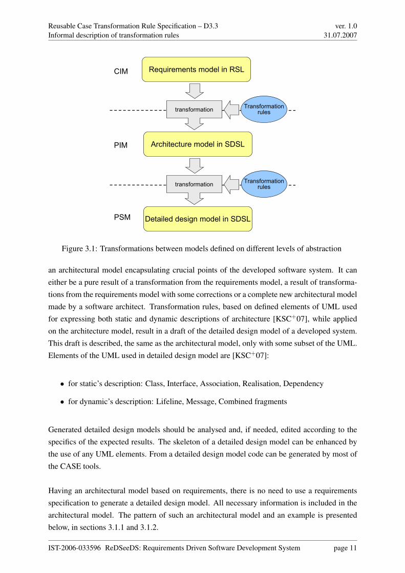
The Software Case Language (SCL) contains descriptions for requirements, architecture, de-tailed design and code models. From pure functional requirements based on domain speci-fication we can obtain a code model by use of transformations between intermediate models(architecture, detailed design). SCL specifies rules for transformations of these models (seeFigure 3.1). Intermediate models may be analysed and edited in order to include informationomitted during transformation (e.g non-functional requirements).
The architectural model, which is a result of transformation from requirements model, is builtwith some subset of the UML, as transformation rules are limited to such elements of UML as[KSC+07] defines:
• for static’s description: Component, Interface, Dependency, Class, Package
• for dynamic’s description: Lifeline, Message
A generated model should be corrected and completed by a software architect. There is com-plete freedom of using UML elements not limited by any rules, but there must be kept a con-sistency with the requirements specification. Having the architectural model, transformationrules to detailed design model can be applied. The source of these transformations should be
IST-2006-033596 ReDSeeDS: Requirements Driven Software Development System page 10
Reusable Case Transformation Rule Specification – D3.3Informal description of transformation rules
ver. 1.031.07.2007
Requirements model in RSL
Architecture model in SDSL
Detailed design model in SDSL
transformation Transformationrules
CIM
PIM
PSM
transformation Transformationrules
Figure 3.1: Transformations between models defined on different levels of abstraction
an architectural model encapsulating crucial points of the developed software system. It caneither be a pure result of a transformation from the requirements model, a result of transforma-tions from the requirements model with some corrections or a complete new architectural modelmade by a software architect. Transformation rules, based on defined elements of UML usedfor expressing both static and dynamic descriptions of architecture [KSC+07], while appliedon the architecture model, result in a draft of the detailed design model of a developed system.This draft is described, the same as the architectural model, only with some subset of the UML.Elements of the UML used in detailed design model are [KSC+07]:
• for static’s description: Class, Interface, Association, Realisation, Dependency
• for dynamic’s description: Lifeline, Message, Combined fragments
Generated detailed design models should be analysed and, if needed, edited according to thespecifics of the expected results. The skeleton of a detailed design model can be enhanced bythe use of any UML elements. From a detailed design model code can be generated by most ofthe CASE tools.
Having an architectural model based on requirements, there is no need to use a requirementsspecification to generate a detailed design model. All necessary information is included in thearchitectural model. The pattern of such an architectural model and an example is presentedbelow, in sections 3.1.1 and 3.1.2.
IST-2006-033596 ReDSeeDS: Requirements Driven Software Development System page 11

Reusable Case Transformation Rule Specification – D3.3Informal description of transformation rules
ver. 1.031.07.2007
3.1.1 4-layer architecture model in SCL
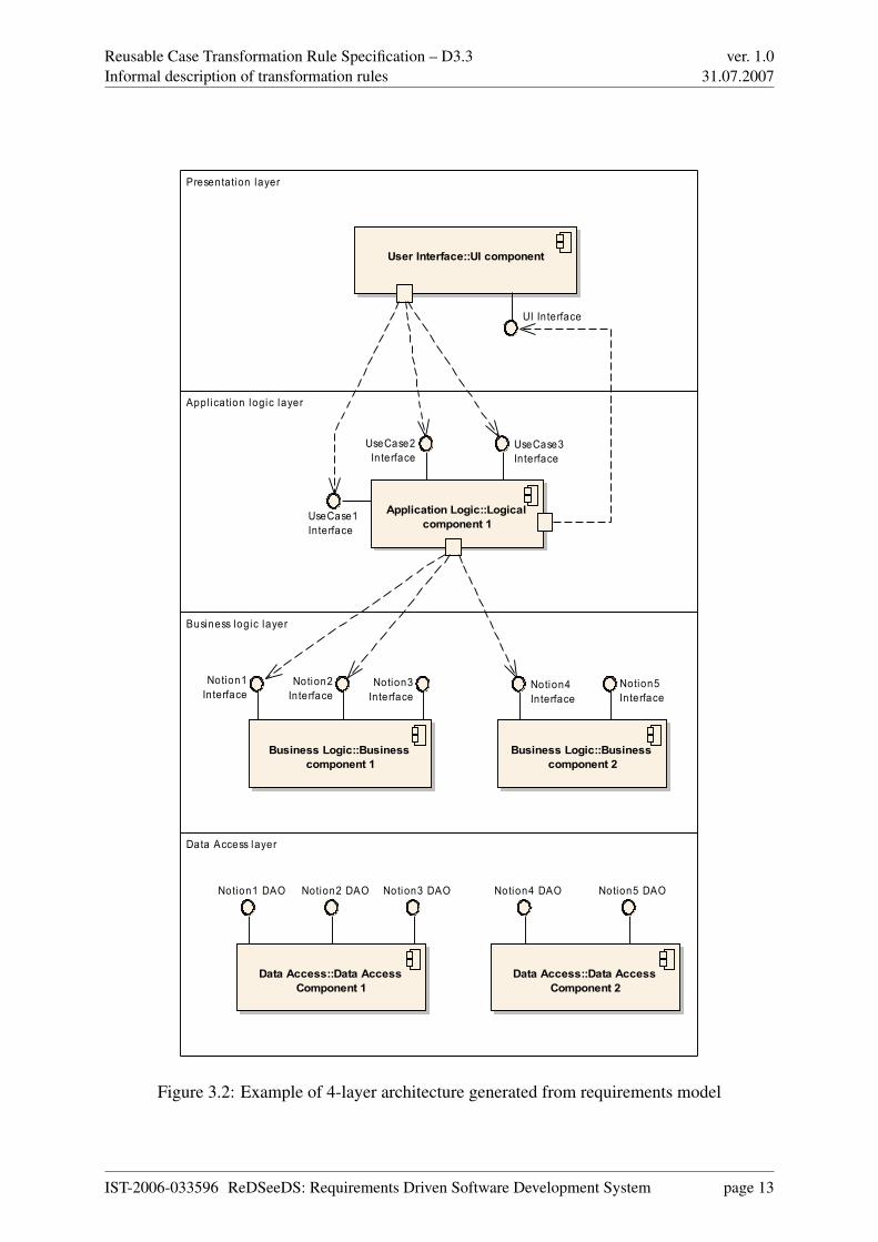
As a typical example of an architecture model in SCL, the model of 4-layer architecture willbe used. It is the most common multi-layer architecture in today’s business software, mostlybecause of the possibility to distribute logical layers among several machines (servers). Themodel describes both the static structure - by component and class diagrams, and the systembehaviour - by sequence diagrams.
Presentation Tier (UI) - one UI component with one interface is built for the whole application.It mediates between a user and the system, “translating” user-system interaction to calls to theApplication Logic tier. Although some logic can be implemented in the UI (like some com-mon sense validation of data entered by user), it is recommended to avoid realising functionalrequirements in this layer.
The Application Logic layer is responsible for the realisation of rules described in functionalrequirements of the system. No business logic should be implemented at this tier, only thelogic that is needed to control the flow of functional requirements (e.g. Use Cases). The layerstructure is designed using component and class diagrams. The application logic layer con-sists of components, which correspond to logically related groups of use cases. Each use casecorresponds to an interface of the corresponding component. Interface contents (operations)are described by means of class diagrams. A components’ creation is based on grouping log-ically related functional requirements. This layer uses Data Transfer Objects (DTOs) for dataexchange with the Business Logic layer.
The Business Logic layer is a tier where all business rules of the system are implemented. Theabove layer, Application Logic, calls interfaces of this tier to retrieve and process data neededto facilitate the flow of user-system interaction. The Business Logic layer calls the Data Accesslayer for basic objects operations used in performing high-level business data manipulation (forinstance validation of sets of data against some aggregated data). The Business logic layerconsists of components, which correspond to related groups of domain concepts - notions. Foreach notion’s corresponding interface of this component is created if there are any businessmethods resulting from functional requirements concerning this notion. This interface is treatedas a service providing business methods.
The Data Access layer is a direct access to data source (like database or flat file) of the system.Please note that there can be more than one data source for a given system. In this tier interfacesexposing basic CRUD (Create/Read/Update/Delete) operations on data access objects (DAOs)are implemented for every notion.
IST-2006-033596 ReDSeeDS: Requirements Driven Software Development System page 12
Reusable Case Transformation Rule Specification – D3.3Informal description of transformation rules
ver. 1.031.07.2007
Presentation layer
Appl ication logic layer
Business logic layer
Data Access layer
Application Logic::Logical component 1
UseCase1Interface
UseCase2Interface
UseCase3Interface
User Interface::UI component
UI Interface
Business Logic::Business component 1
Notion1Interface
Notion2Interface
Notion3Interface
Business Logic::Business component 2
Notion4Interface
Notion5Interface
Data Access::Data Access Component 1
Notion1 DAO Notion2 DAO Notion3 DAO
Data Access::Data Access Component 2
Notion4 DAO Notion5 DAO
Figure 3.2: Example of 4-layer architecture generated from requirements model
IST-2006-033596 ReDSeeDS: Requirements Driven Software Development System page 13

Reusable Case Transformation Rule Specification – D3.3Informal description of transformation rules
ver. 1.031.07.2007
3.1.2 Example of 4-layer architecture in SCL
A part of an architectural model based on the Fitness Club System requirements specification ispresented in this section. It is the result of transformations whose the rules are widely describedin the sections below. The rules have been applied using an automatic technique, but withoutusing any scripting/transformation tool (by manual editing of the architectural model).
The source for the presented transformation was the RSL Elaborate Example, which is a com-plete requirements specification written in the RSL for an imaginary Fitness Club softwareconcept. The specification contains 36 requirements – high-, low-level and non-functional,among these are 12 Use Cases, which have several scenarios. The vocabulary part consists of45 notions with 122 domain statements.
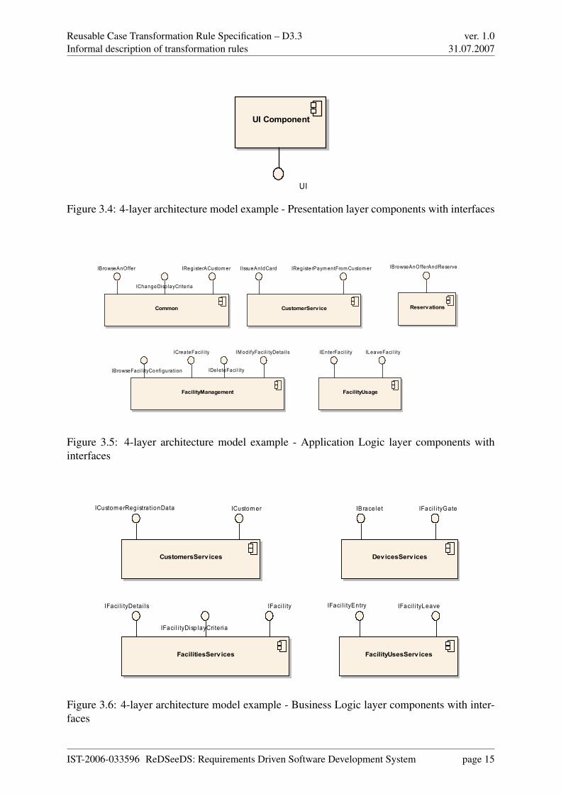
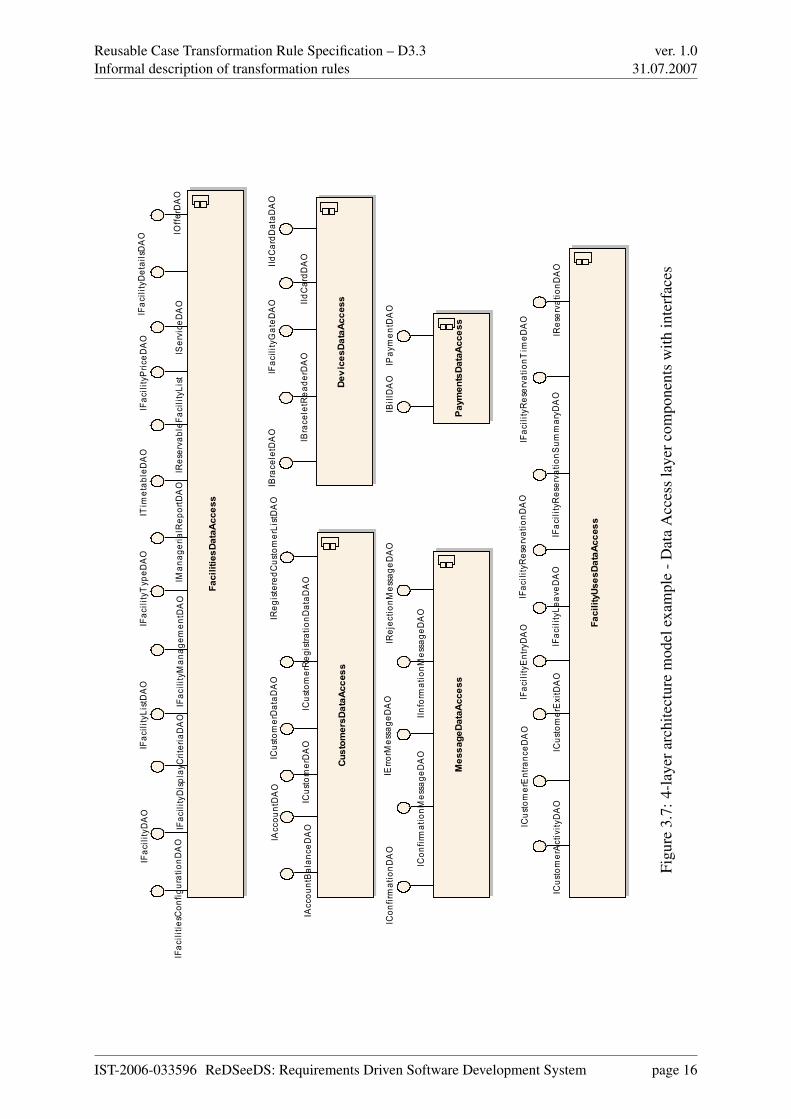
The output of the example transformation is divided into the 4-layer architecture as described inthe example from 3.1.1. The resulting model contains 16 components with 62 interfaces having213 methods and using 40 data transfer objects (DTOs). This gives satisfactory results fromthe perspective of method-per-interface and interface-per-component ratios. Please note thatmost of the components and interfaces exist in the Data Access layer, which also has the mostcomplex components (in terms of number of interfaces).
The components with interfaces for all layers are presented in figures 3.4 – 3.7.
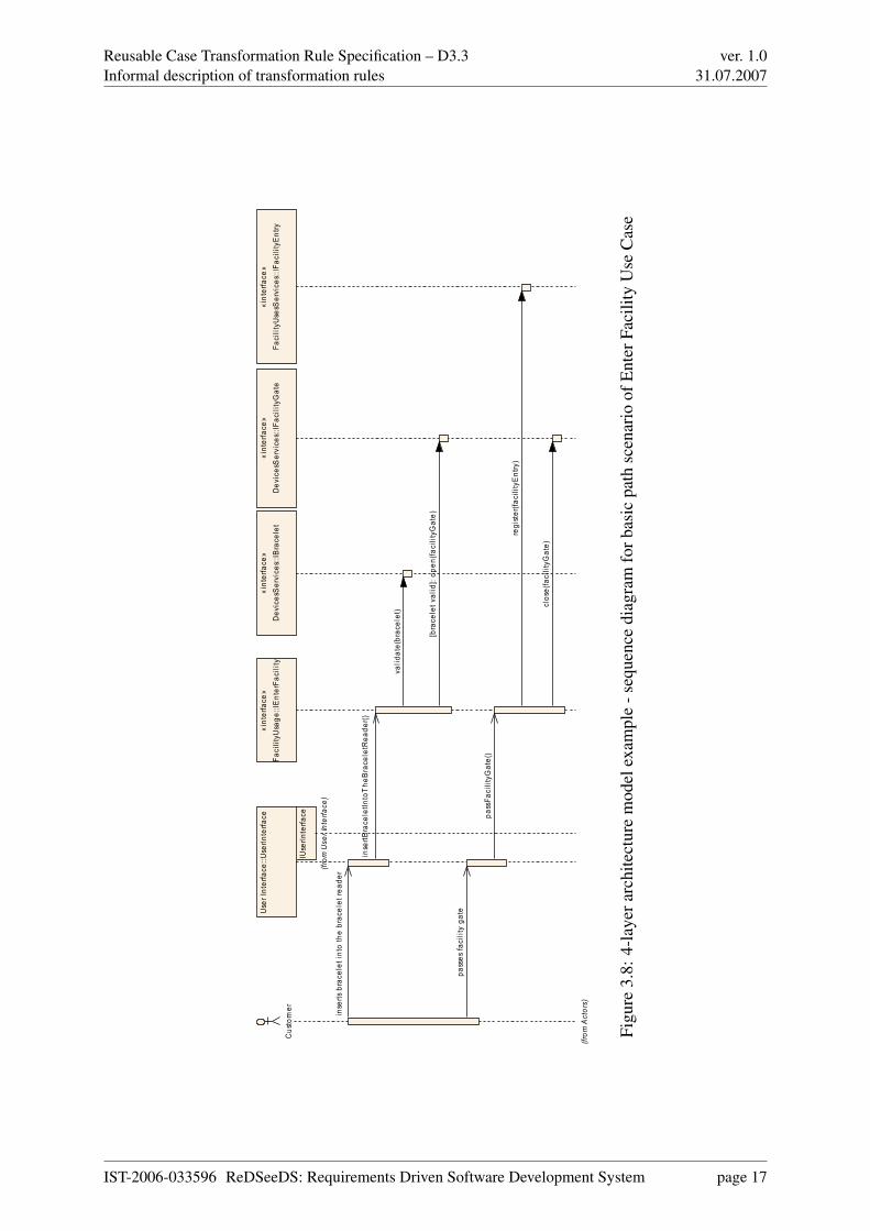
The example also contains a few sequence diagrams for selected use cases, that are shown infigures 3.8 – 3.13.
Customer Receptionist Administrator
User
Figure 3.3: 4-layer architecture model example - actors
IST-2006-033596 ReDSeeDS: Requirements Driven Software Development System page 14
Reusable Case Transformation Rule Specification – D3.3Informal description of transformation rules
ver. 1.031.07.2007
UI Component
UI
Figure 3.4: 4-layer architecture model example - Presentation layer components with interfaces
Common
IBrowseAnOffer
IChangeDisp layCri teria
IRegisterACustomer
CustomerService
IIssueAnIdCard IRegisterPaymentFromCustomer
FacilityManagement
IBrowseFaci l i tyConfiguration
ICreateFaci l i ty
IDe leteFaci l i ty
IModi fyFaci l i tyDeta i ls
FacilityUsage
IEnterFaci l i ty ILeaveFaci l i ty
Reservations
IBrowseAnOfferAndReserve
Figure 3.5: 4-layer architecture model example - Application Logic layer components withinterfaces
CustomersServices
ICustomerRegistrationData ICustomer
FacilitiesServices
IFaci l i tyDetai ls
IFaci l i tyDisp layCri teria
IFaci l i ty
FacilityUsesServices
IFaci l i tyEntry IFaci l i tyLeave
DevicesServices
IBracelet IFaci l i tyGate
Figure 3.6: 4-layer architecture model example - Business Logic layer components with inter-faces
IST-2006-033596 ReDSeeDS: Requirements Driven Software Development System page 15
Reusable Case Transformation Rule Specification – D3.3Informal description of transformation rules
ver. 1.031.07.2007
FacilitiesDataAccess
IFac
ilitie
sCon
figurationD
AO
IFac
ilityDAO
IFac
ilityDetailsDAO
IFac
ilityDisplay
CriteriaDAO
IFac
ilityListDAO
IFac
ilityMan
agem
entDAO
IFac
ilityPric
eDAO
IFac
ilityTyp
eDAO
IMan
agerialRep
ortDAO
IOffe
rDAO
IReserva
bleF
acilityList
IService
DAO
ITim
etab
leDAO
CustomersDataAccess
IAccou
ntBalan
ceDAO
IAccou
ntDAO
ICustomerDAO
ICustomerDataD
AO
ICustomerReg
istra
tionD
ataD
AO
IReg
isteredC
ustomerListDAO
DevicesDataAccess
IBrace
letDAO
IBrace
letRea
derDAO
IFac
ilityGateD
AO IId
CardD
AO
IIdCardD
ataD
AO
PaymentsDataAccess
IBillDAO
IPay
men
tDAO
MessageDataAccess
ICon
firmationD
AO
ICon
firmationM
essage
DAO
IErro
rMessage
DAO
IInform
ationM
essage
DAO
IRejec
tionM
essage
DAO
FacilityUsesDataAccess
ICustomerActivity
DAO
ICustomerEntranc
eDAO
ICustomerExitDAO
IFac
ilityEntryDAO
IFac
ilityLe
aveD
AO
IFac
ilityReserva
tionD
AO
IFac
ilityReserva
tionS
ummaryD
AO
IFac
ilityReserva
tionT
imeD
AO
IReserva
tionD
AO
Figu
re3.
7:4-
laye
rarc
hite
ctur
em
odel
exam
ple
-Dat
aA
cces
sla
yerc
ompo
nent
sw
ithin
terf
aces
IST-2006-033596 ReDSeeDS: Requirements Driven Software Development System page 16
Reusable Case Transformation Rule Specification – D3.3Informal description of transformation rules
ver. 1.031.07.2007
Cus
tom
er
(from
Act
ors)
Use
r Int
erfa
ce::U
serIn
terfa
ce«i
nter
face
»Fa
cilit
yUsa
ge::I
Ent
erFa
cilit
y«i
nter
face
»D
evic
esS
ervi
ces:
:IBra
cele
t«i
nter
face
»D
evic
esS
ervi
ces:
:IFac
ility
Gat
e«i
nter
face
»Fa
cilit
yUse
sSer
vice
s::IF
acili
tyE
ntry
IUse
rInte
rface
(from
Use
r Int
erfa
ce)
inse
rts b
race
let i
nto
the
brac
elet
read
er
inse
rtBra
cele
tInto
The
Bra
cele
tRea
der()
valid
ate(
brac
elet
)
[bra
cele
t val
id]:
open
(faci
lityG
ate)
pass
es fa
cilit
y ga
te
pass
Faci
lityG
ate(
)
regi
ster
(faci
lityE
ntry
)
clos
e(fa
cilit
yGat
e)
Figu
re3.
8:4-
laye
rarc
hite
ctur
em
odel
exam
ple
-seq
uenc
edi
agra
mfo
rbas
icpa
thsc
enar
ioof
Ent
erFa
cilit
yU
seC
ase
IST-2006-033596 ReDSeeDS: Requirements Driven Software Development System page 17

Reusable Case Transformation Rule Specification – D3.3Informal description of transformation rules
ver. 1.031.07.2007
Cus
tom
er
(from
Act
ors)
Use
r Int
erfa
ce::U
serIn
terfa
ce«i
nter
face
»Fa
cilit
yUsa
ge::I
Ent
erFa
cilit
y«i
nter
face
»D
evic
esS
ervi
ces:
:IBra
cele
t
IUse
rInte
rface
(from
Use
r Int
erfa
ce)
inse
rts b
race
let i
nto
the
brac
elet
read
er
inse
rtBra
cele
tInto
The
Bra
cele
tRea
der()
valid
ate(
brac
elet
)
[bra
cele
t inv
alid
]: em
itRej
ectio
nMes
sage
()
Figu
re3.
9:4-
laye
rarc
hite
ctur
em
odel
exam
ple
-seq
uenc
edi
agra
mfo
r1st
alte
rnat
epa
thsc
enar
ioof
Ent
erFa
cilit
yU
seC
ase
IST-2006-033596 ReDSeeDS: Requirements Driven Software Development System page 18

Reusable Case Transformation Rule Specification – D3.3Informal description of transformation rules
ver. 1.031.07.2007
Cus
tom
er
(from
Act
ors)
Use
r Int
erfa
ce::U
serIn
terfa
ce«i
nter
face
»Fa
cilit
yUsa
ge::I
Ent
erFa
cilit
y«i
nter
face
»D
evic
esS
ervi
ces:
:IBra
cele
t«i
nter
face
»D
evic
esS
ervi
ces:
:IFac
ility
Gat
e
IUse
rInte
rface
(from
Use
r Int
erfa
ce)
inse
rts b
race
let i
nto
the
brac
elet
read
er
inse
rtBra
cele
tInto
The
Bra
cele
tRea
der()
valid
ate(
brac
elet
) open
(faci
lityG
ate)
[tim
e ou
t]: c
lose
(faci
lityG
ate)
Figu
re3.
10:4
-lay
erar
chite
ctur
em
odel
exam
ple
-seq
uenc
edi
agra
mfo
r2nd
alte
rnat
epa
thsc
enar
ioof
Ent
erFa
cilit
yU
seC
ase
IST-2006-033596 ReDSeeDS: Requirements Driven Software Development System page 19
Reusable Case Transformation Rule Specification – D3.3Informal description of transformation rules
ver. 1.031.07.2007
Cus
tom
er
(from
Act
ors)
Use
r Int
erfa
ce::U
serIn
terfa
ce«i
nter
face
»R
eser
vatio
ns::I
Bro
wse
AnO
fferA
ndR
eser
ve«i
nter
face
»C
usto
mer
sSer
vice
s::IC
usto
mer
«int
erfa
ce»
Com
mon
::IC
hang
eDis
play
Crit
eria
IUse
rInte
rface
(from
Use
r Int
erfa
ce)
wan
ts to
mak
e fa
cilit
y re
serv
atio
n
wan
tToM
akeF
acili
tyR
eser
vatio
n()
show
Res
erva
bleF
acili
tyLi
st()
[requ
est]:
wan
ts to
cha
nge
faci
lity
disp
lay
crite
ria
[requ
est]:
wan
tToC
hang
eDis
play
Crit
eria
()
sele
cts
faci
lity
sele
ctFa
cilit
y()
askT
oSel
ectF
acili
tyR
eser
vatio
nTim
e()
sele
cts
faci
lity
rese
rvat
ion
time
from
tim
e ta
ble
sele
ctFa
cilit
yRes
erva
tionT
imeF
rom
Tim
etab
le()
askT
oCon
firm
Faci
lityR
eser
vatio
n()
conf
irms
faci
lity
rese
rvat
ion
conf
irmFa
cilit
yRes
erva
tion(
)
rese
rveF
acili
ty(c
usto
mer
,faci
lity)
show
Faci
lityR
eser
vatio
nSum
mar
y()
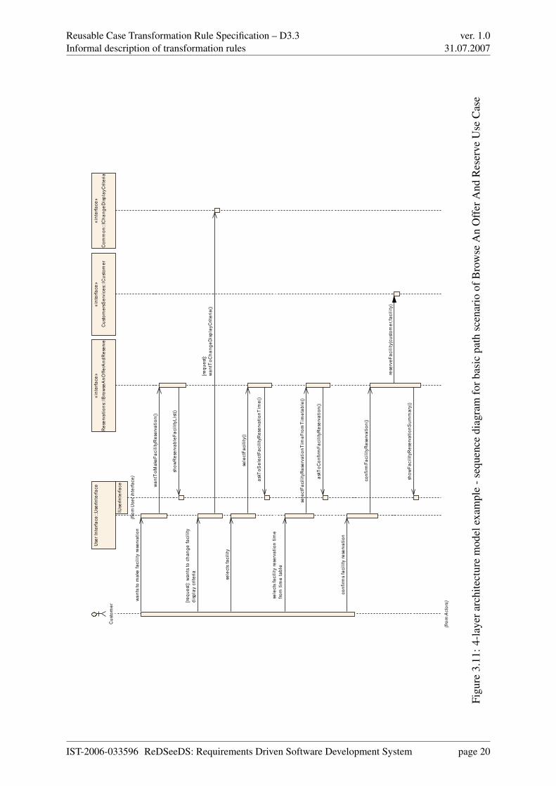
Figu
re3.
11:4
-lay
erar
chite
ctur
em
odel
exam
ple
-seq
uenc
edi
agra
mfo
rbas
icpa
thsc
enar
ioof
Bro
wse
An
Off
erA
ndR
eser
veU
seC
ase
IST-2006-033596 ReDSeeDS: Requirements Driven Software Development System page 20

Reusable Case Transformation Rule Specification – D3.3Informal description of transformation rules
ver. 1.031.07.2007
Use
r Int
erfa
ce::U
serIn
terfa
ce«i
nter
face
»R
eser
vatio
ns::I
Bro
wse
AnO
fferA
ndR
eser
ve«i
nter
face
»C
usto
mer
sSer
vice
s::IC
usto
mer
«int
erfa
ce»
Com
mon
::IC
hang
eDis
play
Crit
eria
Cus
tom
er
(from
Act
ors)
IUse
rInte
rface
(from
Use
r Int
erfa
ce)
wan
ts to
mak
e fa
cilit
y re
serv
atio
n
wan
tToM
akeF
acili
tyR
eser
vatio
n()
show
Res
erva
bleF
acili
tyLi
st()
[requ
est]:
wan
ts to
cha
nge
faci
lity
disp
lay
crite
ria
[requ
est]:
wan
tToC
hang
eDis
play
Crit
eria
()
[list
is e
mpt
y]: s
how
Info
rmat
ionM
essa
ge()
[inse
rt]: w
antT
oCha
ngeD
ispl
ayC
riter
ia()
[rejo
in]:
show
Res
erva
bleF
acili
tyLi
st()
Figu
re3.
12:4
-lay
erar
chite
ctur
em
odel
exam
ple
-seq
uenc
edi
agra
mfo
r1st
alte
rnat
epa
thsc
enar
ioof
Bro
wse
An
Off
erA
ndR
eser
veU
seC
ase
IST-2006-033596 ReDSeeDS: Requirements Driven Software Development System page 21

Reusable Case Transformation Rule Specification – D3.3Informal description of transformation rules
ver. 1.031.07.2007
Cus
tom
er
(from
Act
ors)
Use
r Int
erfa
ce::U
serIn
terfa
ce«i
nter
face
»R
eser
vatio
ns::I
Bro
wse
AnO
fferA
ndR
eser
ve«i
nter
face
»C
usto
mer
sSer
vice
s::IC
usto
mer
«int
erfa
ce»
Com
mon
::IC
hang
eDis
play
Crit
eria
IUse
rInte
rface
(from
Use
r Int
erfa
ce)
wan
ts to
mak
e fa
cilit
y re
serv
atio
n
wan
tToM
akeF
acili
tyR
eser
vatio
n()
show
Res
erva
bleF
acili
tyLi
st()
[requ
est]:
wan
ts to
cha
nge
faci
lity
disp
lay
crite
ria
[requ
est]:
wan
tToC
hang
eDis
play
Crit
eria
()
sele
cts
faci
lity
sele
ctFa
cilit
y()
askT
oSel
ectF
acili
tyR
eser
vatio
nTim
e()
sele
cts
faci
lity
rese
rvat
ion
time
from
tim
e ta
ble
sele
ctFa
cilit
yRes
erva
tionT
imeF
rom
Tim
etab
le()
askT
oCon
firm
Faci
lityR
eser
vatio
n()
disc
ards
faci
lity
rese
rvat
ion
disc
ardF
acili
tyR
eser
vatio
n()
[rejo
in]:
show
Res
erva
bleF
acili
tyLi
st()
Figu
re3.
13:4
-lay
erar
chite
ctur
em
odel
exam
ple
-seq
uenc
edi
agra
mfo
r2nd
alte
rnat
epa
thsc
enar
ioof
Bro
wse
An
Off
erA
ndR
eser
veU
seC
ase
IST-2006-033596 ReDSeeDS: Requirements Driven Software Development System page 22
Reusable Case Transformation Rule Specification – D3.3Informal description of transformation rules
ver. 1.031.07.2007
3.2 Transformations from RSL (requirements model) to architecture model
The purpose of requirements-architecture transformations is generating a draft of an architec-tural model based on the precise requirements specification. Rules of these transformationsshould fulfil following criteria:
• the result architecture model should conform to good practises of creating such models(proper granularity of components, good ratio of interfaces per component and methodsper interface, etc.)
• changes in source model should have predictable impact on result (target) model
• the rules should be flexible (customisable in part at least)
The precise requirements specification should be the result of collective activities of an ana-lyst and an architect. Some analytical decisions have an important influence on the architecturalmodel and should be made during creation of requirements specification (e.g. grouping vocabu-lary notions into vocabulary packages and functional requirements into requirements packages).
Having precise, RSL-compliant requirements specification as a source of transformation, a draftof a 4-layer architecture (transformation target, the significance of all tiers of 4-layer architec-tures is described in section 3.1.1) can be generated by applying following rules1 (see Fig. 3.14,3.15):
• every vocabulary package is transformed into one business component and one data ac-cess component
• every notion used in an SVO sentence is transformed into a data transfer object (DTO).Notions which occur only in “high-level requirements” and system vision are ignored.Every relation between notions is transformed into association between correspondingDTO classes. Associations between DTO classes reflects direction and multiplicities ofnotions’ relations (if present).
• for every notion used in an SVO sentence, a DAO interface is generated in the corre-sponding data access component. This interface will provide CRUD operations for anygiven notion.
1This set of rules is refined from [KSC+07]
IST-2006-033596 ReDSeeDS: Requirements Driven Software Development System page 23

Reusable Case Transformation Rule Specification – D3.3Informal description of transformation rules
ver. 1.031.07.2007
Presentation layer
Appl ica tion logic layer
Business logic layer
Data Access layer
Application Logic::Logical component 1
UseCase1Interface
UseCase2Interface
UseCase3In terface
Application Logic::Logical component 2
UseCase4Interface
UseCase5Interface
User Interface::UI component
UI Interface
Business Logic::Business component 1
Notion1Interface
Notion2Interface
Notion3Interface
Business Logic::Business component 2
Notion4In terface
Notion5In terface
Business Logic::Business component 3
Notion6Interface
Notion7In terface
Data Access::Data Access Component 1
Notion1 DAO Notion2 DAO Notion3 DAO
Data Access::Data Access Component 3
Notion6 DAO Notion7 DAO
Data Access::Data Access Component 2
Notion4 DAO Notion5 DAO
Functional requirements package 1
+ Use Case 1+ Use Case 2+ Use Case 3
Functional requirements package 2
+ Use Case 4+ Use Case 5
Vocabulary notions package 1
+ Notion 1+ Notion 2+ Notion 3
Vocabulary notions package 2
+ Notion 4+ Notion 5
Vocabulary notions package 3
+ Notion 6+ Notion 7
Figure 3.14: 4-layer architecture generation overview
IST-2006-033596 ReDSeeDS: Requirements Driven Software Development System page 24

Reusable Case Transformation Rule Specification – D3.3Informal description of transformation rules
ver. 1.031.07.2007
«interface»Notion3 DAO
+ create(Notion3) : void+ delete(Notion3) : vo id+ read(Notion3) : vo id+ update(Notion3) : vo id
«interface»Business Logic::Notion1 Interface
+ verb(object) : vo id
«interface»Application Logic::UseCase1 Interface
+ actorPredicate() : vo id+ in i tia lActorPredicate() : vo id
«interface»Application Logic::UseCase2 Interface
+ in i tia lPredicate() : void
«interface»User Interface::UI Interface
+ systemCondi tionalPredicate() : vo id+ systemPredicate() : vo id
Presenta tion layer
App l ica tion log ic layer
Business logic layer
Data Access layer
Application Logic::Logical component 1
UseCase1In terface
UseCase2In terface
UseCase3In terface
Application Logic::Logical component 2
UseCase4Interface
UseCase5In terface
User Interface::UI component
UI In terface
Business Logic::Business component 1
Notion1In terface
Notion2In terface
Notion3In terface
Business Logic::Business component 2
Notion4Interface
Notion5In terface
Business Logic::Business component 3
Notion6In terface
Notion7In terface
Data Access::Data Access Component 1
Notion1 DAO Notion2 DAO Notion3 DAO
Data Access::Data Access Component 3
Notion6 DAO Notion7 DAO
Data Access::Data Access Component 2
Notion4 DAO Notion5 DAO
Figure 3.15: 4-layer architecture generation - interfaces
IST-2006-033596 ReDSeeDS: Requirements Driven Software Development System page 25
Reusable Case Transformation Rule Specification – D3.3Informal description of transformation rules
ver. 1.031.07.2007
• a notion in a given vocabulary package is transformed into one interface provided by abusiness component. An interface corresponding to this vocabulary notion is generatedonly if the method for this notion is called on a business component (in the scenario wehave self message with this notion in predicate).
• every functional requirements package is transformed into one application logic compo-nent; it is important to keep the number of functional requirements in packages low (forinstance: less than 4), to prevent creation of too complex components with too manyinterfaces (see also next rule)
• every UseCase (functional requirement) is transformed into one interface provided byapplication logic component
• one UI component with one interface is generated for the whole application; further divi-sion of this component can be done by an architect at a later stage, when storyboards areready and UIElements are placed in the vocabulary
• all actors are transferred with no changes to architectural model
3.2.1 Generating architectural details
To generate further architectural detail, a sequence diagram from a requirements specificationneeds to be transformed into a sequence diagram for the generated architecture.
In requirements sequence diagram we have several types of messages:
• initial actor predicate - the first message from an actor to the system
• actor’s predicate - every message from actor to the system (Every sentence with actor assubject)
• system predicate - every message from the system to the actor (Every sentence with sys-tem as subject, followed by sentence with Actor as subject)
• System’s “self-message” - every message from the system to itself (Every sentence withsystem as subject, followed sentence with system as subject)
Based on the above terminology we should apply the following rules of transformation to createa more detailed architectural model (see Fig. 3.16):
IST-2006-033596 ReDSeeDS: Requirements Driven Software Development System page 26

Reusable Case Transformation Rule Specification – D3.3Informal description of transformation rules
ver. 1.031.07.2007
Actor
System
Use Case 2
precond i tionprecond i tion
successsuccess
in i tia l actor p red ica te
<<invoke/insert>>
system pred icate
actor pred ica te
se l f p red icate
[cond i tion]: system cond i tional p red icate
Actor
User In te rface::UI com ponent « in te rface»Appl ication Logic::UseCase1
Inte rface
« in terface»Appl i ca tion Logic::UseCase2
Interface
«in terface»Business Logic::Notion1
In terface
UI In terface
(from User In terface)
in i tia l actor pred icate
in i tia l acto r pred ica te
invoke m essage
system pred icate
actor p red icate
actor p red icate
se l f pred icate
[cond i tion]: system condi tiona l pred ica te
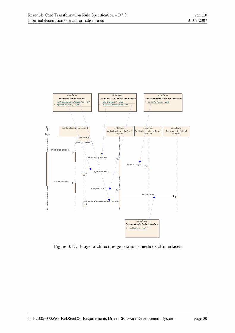
Figure 3.16: 4-layer architecture generation - sequence diagrams
IST-2006-033596 ReDSeeDS: Requirements Driven Software Development System page 27
Reusable Case Transformation Rule Specification – D3.3Informal description of transformation rules
ver. 1.031.07.2007
• initial actor predicate (description of an action that initiates a UseCase) is transformedinto two calls: one from Actor to presentation layer component and the other one frompresentation layer component to application logic component 2. Also, a dependency be-tween the presentation layer component and the application logic component’s interfaceused in this call should be created.
• each actor predicate is transformed analogously to initial actor’s predicate
• every system predicate (description of an action that is a system’s response to Actorsactivity) is transformed into call from application logic layer component to presentationlayer component
• every “invoke” construct is transformed into call from “current” application logic layercomponent (the one for “current” UseCase) to application logic layer component of in-voked UseCase
• every System’s “self-message” is transformed into call from application logic layer com-ponent to business layer component; this business layer component corresponds to a no-tion which occurs in a predicate in an object. For this call a dependency between “source”application logic layer component and “target” business layer component’s interface usedin this call should be created in the architectural model.
• each of the above calls is transformed into a method of a related interface
• calls to business logic layer component’s interface should correspond to verb phrases ofNotion which forms this interface (see Fig. 3.17):
– if verb phrase in predicate is a simple verb phrase, then verb is used for the method’sname, and object part of predicate is a method’s parameter (example: [[v: add n:user]] => add(User))
– if phrase is a complex one, then verb and direct object form method’s name and bothdirect and indirect objects are method’s parameters (example: [[v: add n: user p: ton: user list]] => addUser(User, UserList))
• actors in architectural models should be separated from actors from the requirementsmodel (but they should have same names, the architectural model actors are just “copies”of actors used in requirements)
• calls to UI interface are asynchronous by default (but can be changed later by an architectto synchronise if needed)
• no returns are shown on architectural sequence diagrams
2Both components are specific for this UseCase - see above
IST-2006-033596 ReDSeeDS: Requirements Driven Software Development System page 28
Reusable Case Transformation Rule Specification – D3.3Informal description of transformation rules
ver. 1.031.07.2007
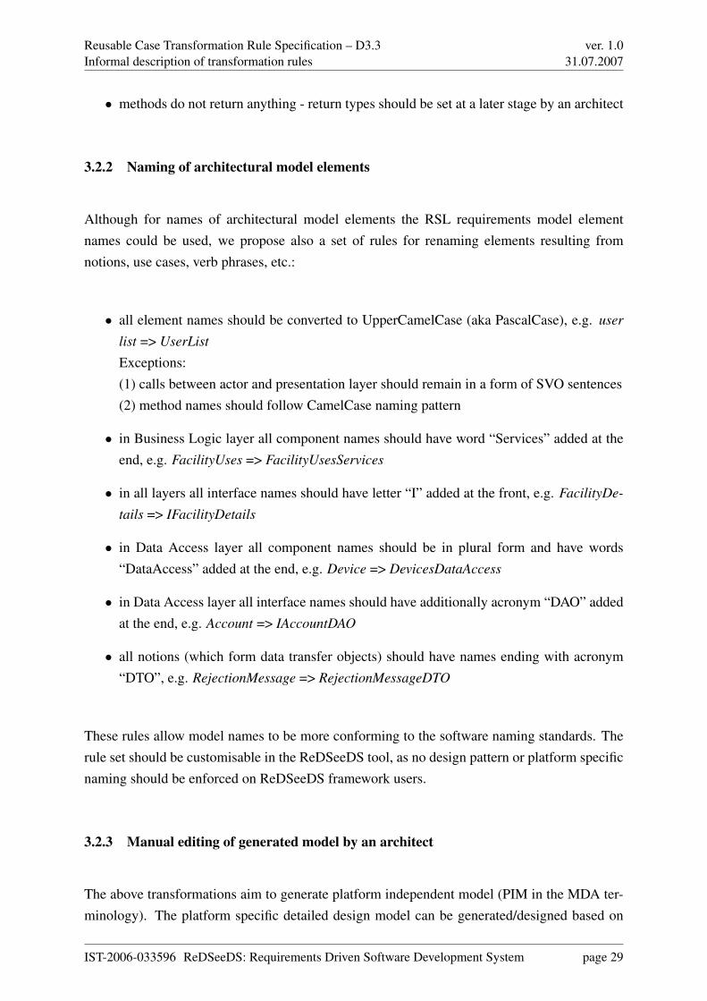
• methods do not return anything - return types should be set at a later stage by an architect
3.2.2 Naming of architectural model elements
Although for names of architectural model elements the RSL requirements model elementnames could be used, we propose also a set of rules for renaming elements resulting fromnotions, use cases, verb phrases, etc.:
• all element names should be converted to UpperCamelCase (aka PascalCase), e.g. user
list => UserList
Exceptions:(1) calls between actor and presentation layer should remain in a form of SVO sentences(2) method names should follow CamelCase naming pattern
• in Business Logic layer all component names should have word “Services” added at theend, e.g. FacilityUses => FacilityUsesServices
• in all layers all interface names should have letter “I” added at the front, e.g. FacilityDe-
tails => IFacilityDetails
• in Data Access layer all component names should be in plural form and have words“DataAccess” added at the end, e.g. Device => DevicesDataAccess
• in Data Access layer all interface names should have additionally acronym “DAO” addedat the end, e.g. Account => IAccountDAO
• all notions (which form data transfer objects) should have names ending with acronym“DTO”, e.g. RejectionMessage => RejectionMessageDTO
These rules allow model names to be more conforming to the software naming standards. Therule set should be customisable in the ReDSeeDS tool, as no design pattern or platform specificnaming should be enforced on ReDSeeDS framework users.
3.2.3 Manual editing of generated model by an architect
The above transformations aim to generate platform independent model (PIM in the MDA ter-minology). The platform specific detailed design model can be generated/designed based on
IST-2006-033596 ReDSeeDS: Requirements Driven Software Development System page 29
Reusable Case Transformation Rule Specification – D3.3Informal description of transformation rules
ver. 1.031.07.2007
«interface»Business Logic::Notion1 Interface
+ verb(object) : vo id
«interface»Application Logic::UseCase1 Interface
+ actorPredicate() : void+ i n i tia lActorPredicate() : vo id
«interface»Application Logic::UseCase2 Interface
+ in i tia lPredicate() : vo id
«interface»User Interface::UI Interface
+ systemCondi tionalPredicate() : vo id+ systemPredicate() : vo id
Actor
User In terface::UI com ponent « interface»Appl ication Logic::UseCase1
Interface
«interface»Appl ication Logic::UseCase2
Interface
«interface»Business Logic::Notion1
Interface
UI In terface
(from User In terface)
in i tia l actor predicate
in i tial actor predicate
invoke m essage
system predicate
actor predicate
actor predicate
self predicate
[condi tion]: system condi tional predicate
Figure 3.17: 4-layer architecture generation - methods of interfaces
IST-2006-033596 ReDSeeDS: Requirements Driven Software Development System page 30

Reusable Case Transformation Rule Specification – D3.3Informal description of transformation rules
ver. 1.031.07.2007
a given architecture (see 3.4), which the architect should carefully examine and improve. Forthis purpose the architect can use any elements of UML, but should have in mind the fact, thatonly the SCL-compliant UML subset can be used for later transformation (from architecture todetailed design).
Some of the decisions made by an architect after generation of the architecture model shouldtake into account difficulties with determining which of the notions should have correspondingDAOs in the final architectural model (e.g. collections for existing DAOs should be removed,as typical, auto-generated CRUD methods do not make sense for lists of objects).
In the ReDSeeDS tool a feature should be implemented to mark an architect’s changes in the fi-nal model, so re-generating the model again from requirements (for example: after requirementchanges) would not overwrite the architect’s work. The solution could be based on keepingtraces between the generated model and the final model. The example of such a link couldbe IsAllocatedTo ([KSC+07], p. 214). Also, changed elements in a model should be indicatedwith some kind of “change flag”. During re-generation of architecture the architect would beprompted for overwriting their changes. Of course there are still few problems to solve: forexample if an architect splits a component into two new components, and after generation anew method appears in the original component, the decision has to be taken: to which of theresulting two components the new method should be added.
Presented transformation rules are appropriate for generating 4-layer architecture. For otherarchitectures (like for the real time systems, service-oriented architectures or client-server ar-chitecture) different transformation rules should be proposed. In fact we need a “family” oftransformations which probably should be customisable.
While 4-layer architecture seems to be most illustrative for purpose of creating transformationrules, transforming to other architectures following the layer architectural design patterns couldbe based on rules presented above; e.g. transforming to 3-layer architecture could be very simi-lar with exception of merging UI and application logic layers (calls between UI and applicationlogic become UI layer self-messages).
IST-2006-033596 ReDSeeDS: Requirements Driven Software Development System page 31
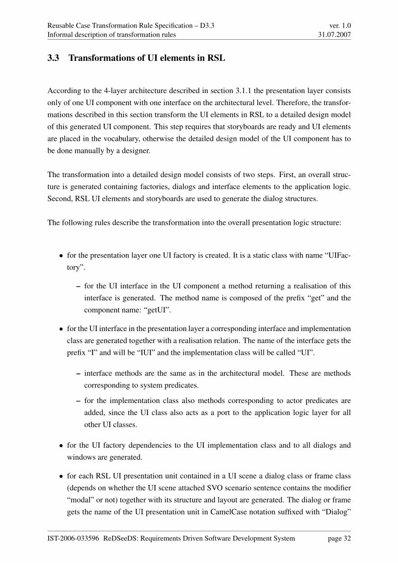
Reusable Case Transformation Rule Specification – D3.3Informal description of transformation rules
ver. 1.031.07.2007
3.3 Transformations of UI elements in RSL
According to the 4-layer architecture described in section 3.1.1 the presentation layer consistsonly of one UI component with one interface on the architectural level. Therefore, the transfor-mations described in this section transform the UI elements in RSL to a detailed design modelof this generated UI component. This step requires that storyboards are ready and UI elementsare placed in the vocabulary, otherwise the detailed design model of the UI component has tobe done manually by a designer.
The transformation into a detailed design model consists of two steps. First, an overall struc-ture is generated containing factories, dialogs and interface elements to the application logic.Second, RSL UI elements and storyboards are used to generate the dialog structures.
The following rules describe the transformation into the overall presentation logic structure:
• for the presentation layer one UI factory is created. It is a static class with name “UIFac-tory”.
– for the UI interface in the UI component a method returning a realisation of thisinterface is generated. The method name is composed of the prefix “get” and thecomponent name: “getUI”.
• for the UI interface in the presentation layer a corresponding interface and implementationclass are generated together with a realisation relation. The name of the interface gets theprefix “I” and will be “IUI” and the implementation class will be called “UI”.
– interface methods are the same as in the architectural model. These are methodscorresponding to system predicates.
– for the implementation class also methods corresponding to actor predicates areadded, since the UI class also acts as a port to the application logic layer for allother UI classes.
• for the UI factory dependencies to the UI implementation class and to all dialogs andwindows are generated.
• for each RSL UI presentation unit contained in a UI scene a dialog class or frame class(depends on whether the UI scene attached SVO scenario sentence contains the modifier“modal” or not) together with its structure and layout are generated. The dialog or framegets the name of the UI presentation unit in CamelCase notation suffixed with “Dialog”
IST-2006-033596 ReDSeeDS: Requirements Driven Software Development System page 32
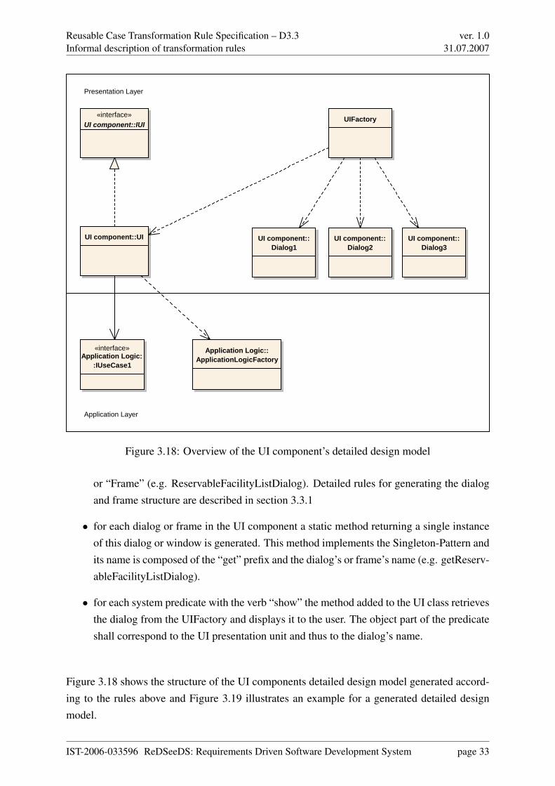
Reusable Case Transformation Rule Specification – D3.3Informal description of transformation rules
ver. 1.031.07.2007
UIFactory
UI component::Dialog1
UI component::Dialog2
UI component::Dialog3
Application Logic::ApplicationLogicFactory
«interface»Application Logic:
:IUseCase1
Application Layer
Presentation Layer
UI component::UI
«interface»UI component::IUI
Figure 3.18: Overview of the UI component’s detailed design model
or “Frame” (e.g. ReservableFacilityListDialog). Detailed rules for generating the dialogand frame structure are described in section 3.3.1
• for each dialog or frame in the UI component a static method returning a single instanceof this dialog or window is generated. This method implements the Singleton-Pattern andits name is composed of the “get” prefix and the dialog’s or frame’s name (e.g. getReserv-ableFacilityListDialog).
• for each system predicate with the verb “show” the method added to the UI class retrievesthe dialog from the UIFactory and displays it to the user. The object part of the predicateshall correspond to the UI presentation unit and thus to the dialog’s name.
Figure 3.18 shows the structure of the UI components detailed design model generated accord-ing to the rules above and Figure 3.19 illustrates an example for a generated detailed designmodel.
IST-2006-033596 ReDSeeDS: Requirements Driven Software Development System page 33
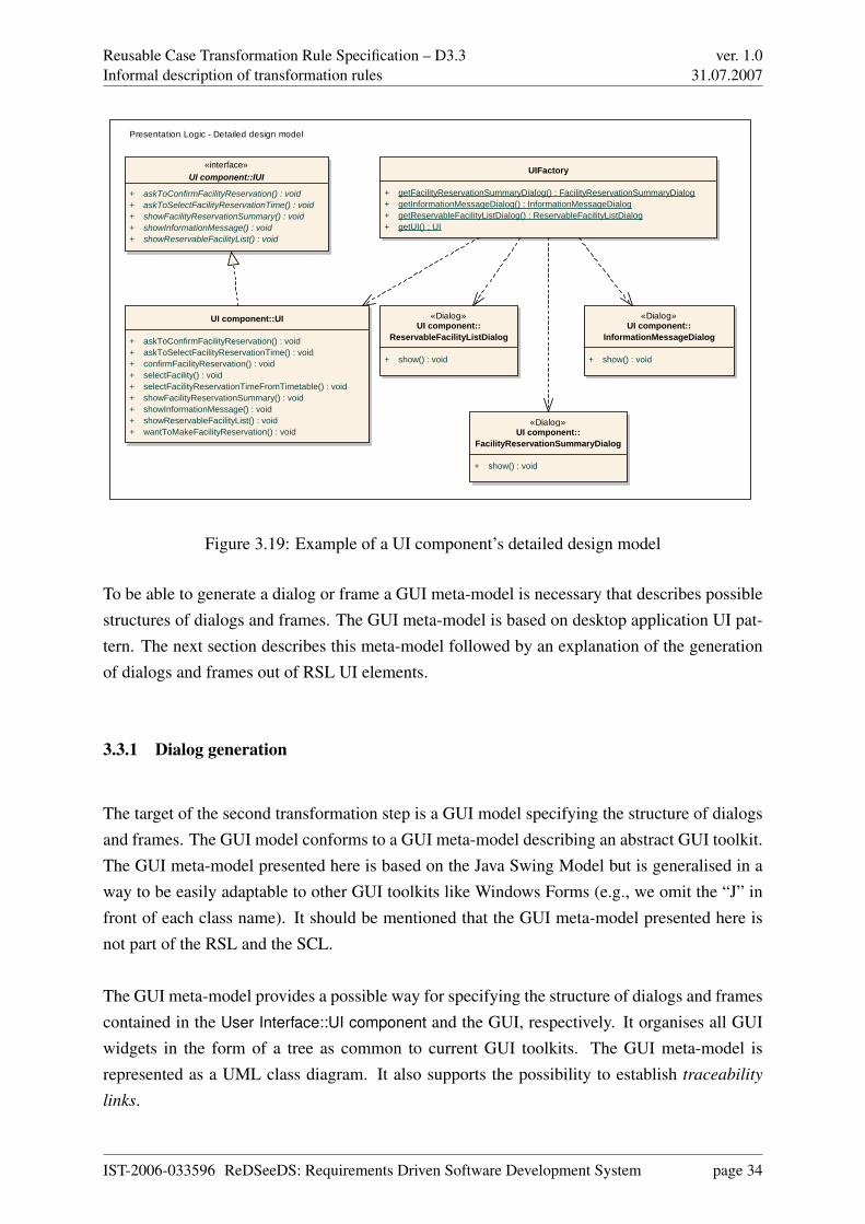
Reusable Case Transformation Rule Specification – D3.3Informal description of transformation rules
ver. 1.031.07.2007
UIFactory
+ getFacilityReservationSummaryDialog() : FacilityReservationSummaryDialog+ getInformationMessageDialog() : InformationMessageDialog+ getReservableFacilityListDialog() : ReservableFacilityListDialog+ getUI() : UI
«interface»UI component::IUI
+ askToConfirmFacilityReservation() : void+ askToSelectFacilityReservationTime() : void+ showFacilityReservationSummary() : void+ showInformationMessage() : void+ showReservableFacilityList() : void
UI component::UI
+ askToConfirmFacilityReservation() : void+ askToSelectFacilityReservationTime() : void+ confirmFacilityReservation() : void+ selectFacility() : void+ selectFacilityReservationTimeFromTimetable() : void+ showFacilityReservationSummary() : void+ showInformationMessage() : void+ showReservableFacilityList() : void+ wantToMakeFacilityReservation() : void
«Dialog»UI component::
ReservableFacilityListDialog
+ show() : void
«Dialog»UI component::
InformationMessageDialog
+ show() : void
«Dialog»UI component::
FacilityReservationSummaryDialog
+ show() : void
Presentation Logic - Detailed design model
Figure 3.19: Example of a UI component’s detailed design model
To be able to generate a dialog or frame a GUI meta-model is necessary that describes possiblestructures of dialogs and frames. The GUI meta-model is based on desktop application UI pat-tern. The next section describes this meta-model followed by an explanation of the generationof dialogs and frames out of RSL UI elements.
3.3.1 Dialog generation
The target of the second transformation step is a GUI model specifying the structure of dialogsand frames. The GUI model conforms to a GUI meta-model describing an abstract GUI toolkit.The GUI meta-model presented here is based on the Java Swing Model but is generalised in away to be easily adaptable to other GUI toolkits like Windows Forms (e.g., we omit the “J” infront of each class name). It should be mentioned that the GUI meta-model presented here isnot part of the RSL and the SCL.
The GUI meta-model provides a possible way for specifying the structure of dialogs and framescontained in the User Interface::UI component and the GUI, respectively. It organises all GUIwidgets in the form of a tree as common to current GUI toolkits. The GUI meta-model isrepresented as a UML class diagram. It also supports the possibility to establish traceability
links.
IST-2006-033596 ReDSeeDS: Requirements Driven Software Development System page 34

Reusable Case Transformation Rule Specification – D3.3Informal description of transformation rules
ver. 1.031.07.2007
Dialog
LabelComboBox
TextField Button
PanelWindow
Frame
AbstractButton
MenuItem
Widget
TextComponent
TextArea
LayoutManager
FlowLayout
GridBagLayout
GridBagConstraint
Presentation Logic::UI component::UI
+ actorPredicate() : void+ systemPredicate() : void+ initialActorPredicate() : void+ systemConditionalPredicate() : void
«interface»Presentation Logic::UI component::IUI
+ systemPredicate() : void+ systemConditionalPredicate() : void
0..*
+usedLayout
0..1
0..1
1
+parent 1{ordered}
+child0..*
+parent1 {ordered}
+child
0..*
Figure 3.20: A conceptual GUI meta-model
Figure 3.20 shows the GUI meta-model relevant to generating the detailed design of dialogs.The classes and structure of the meta-model are mainly derived from Java Swing. The baseclass for all widgets is the abstract class Widget. The specialised classes Window, Dialog, Frame
and Panel in the left part of Figure 3.20 depict GUI containers that aggregate other widgets.Since in Java Swing each component is also a container, the conceptual GUI meta-model pre-sented here also does not explicitly distinguish between container and non-container elements.Conforming to Java Swing, all GUI widgets can be associated with a LayoutManager, but usu-ally it makes sense to attach layout managers only to GUI containers. Some layout managerslike GridBagLayout assign additional constraints (e.g., row, column, padding, etc.) to the GUIwidgets aggregated in the associated GUI container. Other layout managers like FlowLayout
only depend on the order the widgets are added to the container. This order is assured by theorder constraint of the aggregation between panels or windows and their child widgets.
The content of a window (dialog or frame) is determined by the following rules. If a detailedspecification of an RSL UI presentation unit is available, the following rules apply:
• Every RSL UI container is transformed into a Panel. By default, a FlowLayout is associ-ated with the Panel. The name of the generated panel and flow layout will be the nameof the UI container suffixed with “Panel” and “FlowLayout” respectively. All RSL UIelements contained in the RSL UI container get processed in the order defined by theassociated RSL presentation order. The following rules are applied to the contained RSL
IST-2006-033596 ReDSeeDS: Requirements Driven Software Development System page 35

Reusable Case Transformation Rule Specification – D3.3Informal description of transformation rules
ver. 1.031.07.2007
UI element depending on their specialisation type. Each generated widget is then addedto the Panel.
• Every RSL input UI element is transformed into a TextField and an associated Label. Ifit is possible to determine the type of data through the associated SVO scenario sentence,it is possible to generate a text area, spinner, date/time picker, gauge or slider insteadof a text field. The default text of the generated label will be the predicate of the SVOsentence. If the associated SVO sentence is an actor predicate, an input change methodis generated, that calls the application logic method via the UI class. The name of thegenerated text field and label will be the name of the input UI element suffixed with“TextField” and “Label” respectively.
• Every selection UI element is transformed into either a ComboBox, ListBox, CheckBox orRadioButtons depending on the number of contained RSL option UI elements and on theallowance of multiple selection. For each RSL option UI element a single CheckBox ora single RadioButton is generated depending on the value of the isReSelectable attribute.Additionally, an associated Label is generated. The default text of the generated labelwill be the predicate of the SVO sentence. If the associated SVO sentence is an actorpredicate, a selection change method is generated, that calls the application logic methodvia the UI class (e.g. SelectFacility). The name of the generated input widget will be thename of the input UI element suffixed with the type name. The name of the generatedLabel Widget will be the name of the label element suffixed with “Label”.
• Every RSL trigger UI element associated with an RSL user action results in the corre-sponding specialisation of AbstractButton and an action method assigned to the buttonthat triggers the actor predicate associated with the RSL user action. If the SVO sentenceis an initial actor predicate, a MenuItem specialisation will be generated. The name ofthe generated specialisation of abstract button will be the name of the trigger UI elementsuffixed with “Button” or “MenuItem”.
If no detailed specification of an RSL UI presentation unit is available, the following rules canbe used to generate a first prototype for the detailed design model of the dialogs contained inthe UI component. Those rules enforce the use of English in writing requirements. They can bea guideline for the designer. The detailed design model needs to be manually reworked by thedesigner:
• Every SVO sentence attached to an RSL UI scene where the subject refers to the systemand the verb denotes a required selection by the user like “offer” is transformed into aLabel representing the object and either a ComboBox, ListBox, CheckBox or RadioButtons
depending on the number of contained data and if multiple selection is allowed or not.
IST-2006-033596 ReDSeeDS: Requirements Driven Software Development System page 36

Reusable Case Transformation Rule Specification – D3.3Informal description of transformation rules
ver. 1.031.07.2007
• Every SVO sentence attached to an RSL UI scene where the subject refers to the systemand the verb denotes gathering information from the user like “ask” or “request” is trans-formed into a Panel containing a list of pairs of Label and input widgets. These widgetsrepresent the domain information referred to by the object of the sentence. The name ofthe domain element is transformed into the Label and the type of the domain element de-termines the type of the input widget. By default, the type of the input widget is TextField
allowing to enter any kind of information.
• Every SVO sentence attached to an RSL UI scene where the subject refers to the systemand the verb denotes the presentation of information like “inform” is transformed into aLabel representing the information denoted by the object of the sentence.
• Every SVO sentence attached to an RSL user action where the subject refers to the userof the system results in the creation of a Button that allows submission of information thatthe user entered based on other SVO sentences attached to predecessor RSL UI scene ofthe RSL user action. If there is also a conditional sentence associated with the RSL useraction, the condition evaluation is also included in the action method of the generatedbutton.
Figure 3.21 shows an RSL storyboard for the “Make facility reservation” scenario used as anexample throughout these sections. The storyboard consists of RSL UI scene, each attachedwith a list of SVO sentences and an RSL presentation unit displaying the envisioned dialogstructure. Each RSL UI presentation unit gets transformed into dialogs according to the rulesabove. The generated dialog structure for the “Reservable Facility List Dialog” and the “FacilityReservation Summary Dialog” are shown in Figure 3.22 and Figure 3.23.
The ReservableFacilityListDialog in Figure 3.22 is composed of two Labels, two ComboBoxesand two Buttons. The “UI presentation order” is transformed to an instance of FlowLayout
assigned the ReservableFacilityListDialog. The order is given by the order constraint of theaggregation specified in the GUI meta-model. The flow layout places everything in one rowuntil there is not enough space in the row which leads to switching to the next row. In thereservable facility list dialog only the buttons are placed on the same line.
Figure 3.23 illustrates the GUI Model for the “Facility Reservation Summary Dialog”, whichresults from the UI presentation unit shown in scene 4 in Figure3.21. The dialog is invoked bythe “show facility reservation summary” system predicate. The FacilityReservationSummaryDi-
alog is composed of a Label displaying the status and a Button arranged with a FlowLayout.
Figure 3.24 shows a typical sequence for the “Make facility reservation” scenario. The “wantsto make facility reservation” initial actor predicate leads to the system predicate “show reserv-
IST-2006-033596 ReDSeeDS: Requirements Driven Software Development System page 37

Reusable Case Transformation Rule Specification – D3.3Informal description of transformation rules
ver. 1.031.07.2007
Reservable Facility List
Information Message
Facility Reservation Summary
facility list
facility reservation time
reservecancel
No facility is currently available!
ok
You successfully reserved facility xy.
ok
7. Customer confirms facility reservation.[Facility available]
7. Customer confirms facility reservation.[Facility not available]
2. FCS shows reservable facility list.3. Customer selects facility.4. FCS asks to select facility reservation time.5. Customer selects facility reservation time from timetable.6. FCS asks to confirm facility reservation.
Fitness Club System
File Services Help
Make facility reservation
Scene 1
Scene 2
Scene 3
Scene 4
1. Customer wants to make facility reservation.
8. FCS shows facility reservation status.
8. FCS shows facility reservation status.
facility list:
facility reservation time:
Figure 3.21: UI storyboard for “Make facility reservation” scenario
«Button»ReserveButton
«Dialog»UI component::ReservableFacilityListDialog
+ show() : void
«ComboBox»FacilityListComboBox
«ComboBox»ReservationTimeComboBox
«Button»CancelButton
«Label»FacilityListLabel
«Label»ReservationTimeLabel
«FlowLayout»ReservableFacilityListFlowLayout
Figure 3.22: Reservable facility list dialog structure
IST-2006-033596 ReDSeeDS: Requirements Driven Software Development System page 38
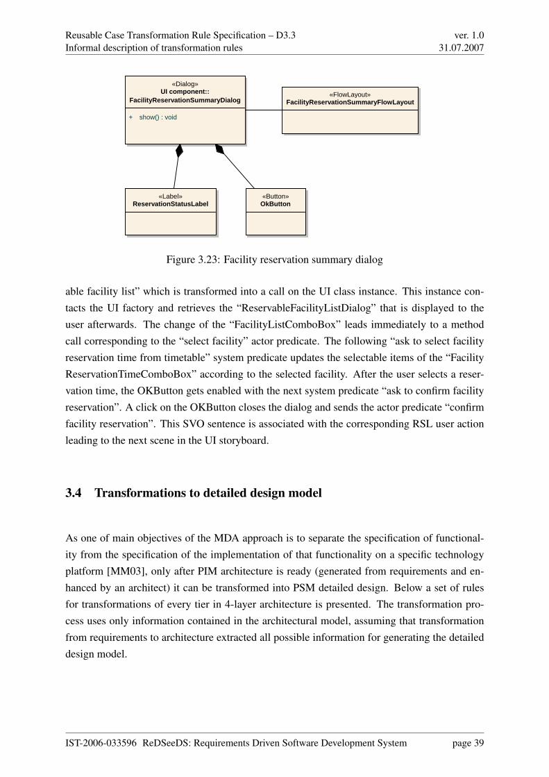
Reusable Case Transformation Rule Specification – D3.3Informal description of transformation rules
ver. 1.031.07.2007
«Dialog»UI component::
FacilityReservationSummaryDialog
+ show() : void
«Button»OkButton
«Label»ReservationStatusLabel
«FlowLayout»FacilityReservationSummaryFlowLayout
Figure 3.23: Facility reservation summary dialog
able facility list” which is transformed into a call on the UI class instance. This instance con-tacts the UI factory and retrieves the “ReservableFacilityListDialog” that is displayed to theuser afterwards. The change of the “FacilityListComboBox” leads immediately to a methodcall corresponding to the “select facility” actor predicate. The following “ask to select facilityreservation time from timetable” system predicate updates the selectable items of the “FacilityReservationTimeComboBox” according to the selected facility. After the user selects a reser-vation time, the OKButton gets enabled with the next system predicate “ask to confirm facilityreservation”. A click on the OKButton closes the dialog and sends the actor predicate “confirmfacility reservation”. This SVO sentence is associated with the corresponding RSL user actionleading to the next scene in the UI storyboard.
3.4 Transformations to detailed design model
As one of main objectives of the MDA approach is to separate the specification of functional-ity from the specification of the implementation of that functionality on a specific technologyplatform [MM03], only after PIM architecture is ready (generated from requirements and en-hanced by an architect) it can be transformed into PSM detailed design. Below a set of rulesfor transformations of every tier in 4-layer architecture is presented. The transformation pro-cess uses only information contained in the architectural model, assuming that transformationfrom requirements to architecture extracted all possible information for generating the detaileddesign model.
IST-2006-033596 ReDSeeDS: Requirements Driven Software Development System page 39

Reusable Case Transformation Rule Specification – D3.3Informal description of transformation rules
ver. 1.031.07.2007
Pre
sent
atio
n Lo
gic
App
licat
ion
Logi
c
Cus
tom
er
:UI
Mak
e Fa
cilit
yR
eser
vatio
n:M
enuI
tem
«int
erfa
ce»
:IBro
wse
AnO
fferA
ndR
eser
ve:U
IFac
tory
Res
erva
bleF
acili
tyLi
stD
ialo
g:D
ialo
gFa
cilit
yLis
tCom
boB
ox:C
ombo
Box
Faci
lityR
eser
vatio
nTim
eCom
boB
ox:C
ombo
Box
OkB
utto
n :B
utto
n
sele
ct
Wan
tToM
akeF
acili
tyR
eser
vatio
n()
Wan
tToM
akeF
acili
tyR
eser
vatio
n()
Sho
wR
eser
vabl
eFac
ility
List
()
getR
eser
vabl
eFac
ility
List
Dia
log(
) :R
eser
vabl
eFac
ility
List
Dia
log
show
()
show
upda
teIte
ms(
)
sele
ct it
em fr
om fa
cilit
y co
mbo
box
Sel
ectF
acili
ty()
Sel
ectF
acili
ty()
Ask
ToS
elec
tFac
ility
Res
erva
tionT
ime(
)
upda
teIte
ms(
)
timet
able
upd
ated
sele
ct it
em fr
om fa
cilit
y re
serv
atio
n tim
e co
mbo
box
Sel
ectF
acili
tyR
eser
vatio
nTim
eFro
mT
imet
able
()
Sel
ectF
acili
tyR
eser
vatio
nTim
eFro
mT
imet
able
()
Ask
ToC
onfir
mFa
cilit
yRes
erva
tion(
)
enab
le()
enab
led
clic
k
Con
firm
Faci
lityR
eser
vatio
n()
Con
firm
Faci
lityR
eser
vatio
n()
Figure 3.24: Customer wants to make facility reservation UI scenario.
IST-2006-033596 ReDSeeDS: Requirements Driven Software Development System page 40

Reusable Case Transformation Rule Specification – D3.3Informal description of transformation rules
ver. 1.031.07.2007
AL
BL
DAL
«in te rface»IChangeDisplayCriteria
« in te rface»IRegisterACustomer
« in te rface»IBrowseAnOfferAndReserveChangeDisplayCriteria
RegisterACustomer
BrowseAnOfferAndReserve
ApplicationLogicFactory
CommonFactory ReservationsFactory
« in te rface»ICustomer
Customer
« in te rface»IFacility
Facility
BusinessLogicFactory
CustomerFactory FacilityFactory
« in te rface»IFacilityDAO
« in te rface»ICustomerDAO
« in te rface»ICustomerDataDAO
CustomerDAO
CustomerDataDAO
FacilityDAO
DataAccessFactory
CustomerDataAccessFactory FacilityDataAccessFactory
ConnectionFactory
+custom er
+faci l i tyDAO+cutomerDAO
Figure 3.25: Overview of detailed design model generated from architectural model
IST-2006-033596 ReDSeeDS: Requirements Driven Software Development System page 41

Reusable Case Transformation Rule Specification – D3.3Informal description of transformation rules
ver. 1.031.07.2007
Appl ica tion Log ic - Arch i tectura l m odel
App l ica tion Log ic - Deata i led design m odel
Application logic::Common
IChangeDisp layCri te ria IReg isterACustom er
Application logic::Reservations
IBrowseAnOfferAndReserve
« interface»Common::IChangeDisplayCriteria
+ EnterFaci l i tyDisp layCri te ria() : vo id+ WantToChangeDisp layCri te ria () : vo id
«interface»Common::IRegisterACustomer
+ EnterCustomerRegistra tionData() : vo id+ WantToRegisterACustomer() : vo id
«in terface»Reservations::IBrowseAnOfferAndReserve
+ Confi rmFaci l i tyReservation() : vo id+ DiscardFaci l i tyReservation() : vo id+ SelectFaci l i ty() : vo id+ SelectFaci l i tyReservationTimeFromTimetab le() : vo id+ WantToMakeFaci l i tyReservation() : vo id
Common::ChangeDisplayCriteria
+ EnterFaci l i tyDisp layCri te ria () : vo id+ WantT oChangeDisp layCri te ria () : vo id
Common::RegisterACustomer
+ EnterCustom erRegistrationData() : vo id+ WantT oRegisterACustom er() : vo id
Reservations::BrowseAnOfferAndReserve
+ Confi rm Faci l i tyReservation() : void+ DiscardFaci l i tyReservation() : vo id+ SelectFaci l i ty() : void+ SelectFaci l i tyReservationT im eFrom T im etab le() : vo id+ WantT oM akeFaci l i tyReservation() : vo id
Application Logic::ApplicationLogicFactory
+ getCom m onFactory() : Com m onFactory+ getReservationsFactory() : ReservationsFactory
Common::CommonFactory
+ getIChangeDisp layCri teria () : IChangeDisp layCri teria+ getIReg isterACustom er() : IReg isterACustom er
Reservations::ReservationsFactory
+ getIBrowseAnOfferAndReserve() : IBrowseAnOfferAndReserve
Figure 3.26: Generation of Application logic detailed design
3.4.1 Generation of Application Logic
Below we present rules for generation of the application logic layer elements, including theirnaming patterns and relationships that may exist among them.
• for the application logic layer one application logic factory is created. It is a static classwith name “AppLogicFactory”.
– for every component in the application logic layer a method returning a componentfactory is generated. The method name is composed of “get” prefix and componentname (e.g. getReservationsFactory)
• for each component in the application logic layer a corresponding component factory iscreated. They are static classes with a name composed of a component name + “Factory”suffix (e.g. ResevervationsFactory)
IST-2006-033596 ReDSeeDS: Requirements Driven Software Development System page 42
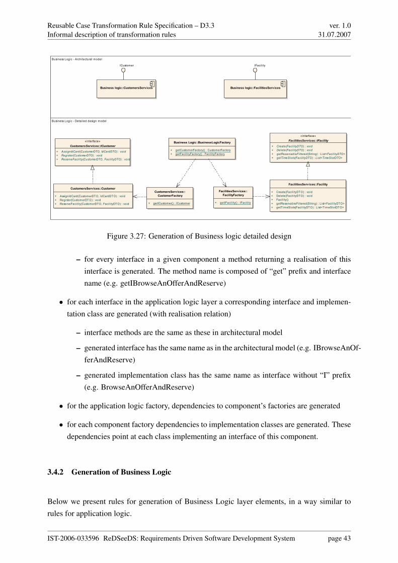
Reusable Case Transformation Rule Specification – D3.3Informal description of transformation rules
ver. 1.031.07.2007
Business Logic - Archi tectural m odel
Business Logic - Detai led design model
Business logic::CustomersServices
ICustomer
Business logic::FacilitiesServ ices
IFaci l i ty
«interface»CustomersServices::ICustomer
+ AssignIdCard(CustomerDTO, IdCardDTO) : void+ Register(CustomerDTO) : void+ ReserveFaci l i ty(CustomerDTO, Faci l i tyDTO) : void
CustomersServices::Customer
+ AssignIdCard(Custom erDT O, IdCardDT O) : void+ Register(CustomerDT O) : void+ ReserveFaci l i ty(Custom erDT O, Faci l i tyDT O) : void
«interface»FacilitiesServices::IFacility
+ Create(Faci l i tyDTO) : void+ Delete(Faci l i tyDTO) : void+ getReservableFi l tered(String) : L ist<Faci l i tyDTO>+ getTimeSlots(Facil i tyDTO) : L ist<TimeSlotDTO>
FacilitiesServ ices::Facility
+ Create(Faci l i tyDTO) : void+ Delete(Faci l i tyDTO) : void+ Facil i ty()+ getReservableFi l tered(String) : L ist<Faci l i tyDT O>+ getT im eSlots(Faci l i tyDT O) : L ist<T im eSlotDT O>
Business Logic::BusinessLogicFactory
+ getCustom erFactory() : CustomerFactory+ getFacil i tyFactory() : Faci l i tyFactory
CustomersServices::CustomerFactory
+ getICustom er() : ICustom er
FacilitiesServices::FacilityFactory
+ getIFaci l i ty() : IFaci l i ty
Figure 3.27: Generation of Business logic detailed design
– for every interface in a given component a method returning a realisation of thisinterface is generated. The method name is composed of “get” prefix and interfacename (e.g. getIBrowseAnOfferAndReserve)
• for each interface in the application logic layer a corresponding interface and implemen-tation class are generated (with realisation relation)
– interface methods are the same as these in architectural model
– generated interface has the same name as in the architectural model (e.g. IBrowseAnOf-ferAndReserve)
– generated implementation class has the same name as interface without “I” prefix(e.g. BrowseAnOfferAndReserve)
• for the application logic factory, dependencies to component’s factories are generated
• for each component factory dependencies to implementation classes are generated. Thesedependencies point at each class implementing an interface of this component.
3.4.2 Generation of Business Logic
Below we present rules for generation of Business Logic layer elements, in a way similar torules for application logic.
IST-2006-033596 ReDSeeDS: Requirements Driven Software Development System page 43
Reusable Case Transformation Rule Specification – D3.3Informal description of transformation rules
ver. 1.031.07.2007
• for business logic layer one business logic factory is created. It is a static class with thename “BusinessLogicFactory”.
– for every component in the business logic layer a method returning component fac-tory is generated. The method name is composed of a “get” prefix and a componentname (e.g. getCustomerServicesFactory)
• for each component in the business logic layer a corresponding component factory iscreated. They are static classes with the name composed of component name + “Factory”suffix (e.g. CustomerServicesFactory)
– for every interface in a given component, method returning realisation of this inter-face is generated. The method name is composed of “get” prefix and interface name(e.g. getICustomer)
• for each interface in the business logic layer a corresponding interface and implementa-tion class are generated (with realisation relation)
– interface methods are the same as these in the architectural model
– a generated interface has the same name as in the architectural model (e.g. ICus-tomer)
– a generated implementation class has the name as interface without “I” prefix (e.g.Customer)
• for business logic factory dependencies to component’s factories are generated
• for each component factory dependencies to implementation classes are generated. Thesedependencies point at each class implementing an interface of this component.
3.4.3 Generation of Data Access Layer
The rules for the data access layer are analogous to the rules presented in previous sections.
• for the data access layer one data access factory is created. It is a static class with name“DataAccessFactory;”.
– for every component in the data access layer a method returning component factoryis generated. The method name is composed of a “get” prefix and a componentname (e.g. getCustomerDataAccessFactory)
IST-2006-033596 ReDSeeDS: Requirements Driven Software Development System page 44

Reusable Case Transformation Rule Specification – D3.3Informal description of transformation rules
ver. 1.031.07.2007
Data Access Layer - Architectural model
Data Access Layer - Detai led design m odel
Data Access layer::CustomersDataAccess
Custom erDAO CustomerDataDAO
Data Access layer::FacilitiesDataAccess
Faci l i tyDAO
«interface»FacilitiesDataAccess::IFacilityDAO
+ create(Faci l i tyDTO) : void+ get(Faci l i tyDTO) : void+ getAl l () : List<Faci l i tyDTO>+ getAl lFi l tered(String) : List<Faci l i tyDTO>+ update(Faci l i tyDTO) : void
«in terface»CustomersDataAccess::ICustomerDAO
+ create(CustomerDTO) : void+ delete(CustomerDTO) : void+ read(CustomerDTO) : void+ reserveFacil i ty()() : void+ update(CustomerDTO) : void
«interface»CustomersDataAccess::ICustomerDataDAO
+ create(CustomerDataDTO) : void+ delete(CustomerDataDTO) : void+ read(CustomerDataDTO) : void+ update (CustomerDataDTO) : void
CustomerDAO
+ create(CustomerDT O) : void+ delete(Custom erDTO) : void+ read(CustomerDT O) : void+ reserveFaci l i ty()() : vo id+ update(Custom erDT O) : void
CustomerDataDAO
+ create(CustomerDataDT O) : vo id+ dele te(CustomerDataDT O) : void+ read(Custom erDataDTO) : void+ update(Custom erDataDT O) : void
FacilitiesDataAccess::FacilityDAO
+ create(Faci l i tyDT O) : void+ get(Faci l i tyDT O) : void+ getAl l () : List<Faci l i tyDT O>+ getAl lFi l tered(String) : List<Faci l i tyDTO>+ update(Faci l i tyDT O) : void
DataAccessFactory
+ getCustomerDataAccessFactory() : Custom erDataAccessFactory+ getFaci l i tyDataAccessFacto ry() : Faci l i tyDataAccessFacto ry
CustomerDataAccessFactory
+ getICustom erDAO() : ICustom erDAO+ getICustom erDataDAO() : ICustomerDataDAO
FacilityDataAccessFactory
+ getIFaci l i tyDAO() : IFaci l i tyDAO
ConnectionFactory
Figure 3.28: Generation of Data access layer detailed design
IST-2006-033596 ReDSeeDS: Requirements Driven Software Development System page 45

Reusable Case Transformation Rule Specification – D3.3Informal description of transformation rules
ver. 1.031.07.2007
• for each component in the data access layer a corresponding component factory is created.They are static classes with a name composed of component name + “Factory” suffix (e.g.CustomerDataAccessFactory)
– for every interface in a given component a method returning realisation of this inter-face is generated. The method name is composed of a “get” prefix and an interfacename (e.g. getICustomerDataDAO)
• for the data access layer one connection factory is created. It is a static class with name“ConnectionFactory”
• for each interface in the data access layer a corresponding interface and implementationclass are generated (with a realisation relation)
– interface methods are the same as those in the architectural model
– generated interfaces have the same name as in the architectural model (e.g. ICus-tomerDataDAO)
– generated implementation classes have the same name as the interface without “I”prefix (e.g. CustomerDataDAO)
• for data access factory dependencies to component’s factories are generated
• for each component factory dependencies to implementation classes are generated. Thesedependencies point at each class implementing an interface of this component.
3.4.4 Generating data transfer objects (DTOs)
All DTOs from the architectural model are copied with associations between them to the de-tailed design model
3.4.5 Generating relationships between layers
Associations between all layers are generated based on sequence diagrams. Messages betweenelements of the application logic layer and business logic layer are generated automaticallyfrom requirements. Messages between elements of the business logic layer and the data accesslayer are not generated during transformation from requirements and can be set manually by anarchitect.
IST-2006-033596 ReDSeeDS: Requirements Driven Software Development System page 46

Reusable Case Transformation Rule Specification – D3.3Informal description of transformation rules
ver. 1.031.07.2007
Relationships between the application logic layer and the business logic layer
• for each class implementing an interface in the application logic layer, which uses thebusiness logic layer, a dependency to the business logic factory is generated
• each message between the application logic layer interface and the business componentinterface in architectural model is transformed into an association between implementa-tion classes in the application logic layer and the business interface in the detailed designmodel. The source of the association is a class implementing interface which is the sourcein the sequence diagram.
Relationships between the business logic layer and the data access layer
• for each class implementing interface in the application logic layer, which uses the dataaccess layer, dependency to the data access factory is generated
• each message between the business logic layer interface and the data access layer interfacein the architectural model is transformed into an association between the implementationclass in the business logic layer and the data access interface in the detailed design model.The source of association is a class implementing interface which is the source in thesequence diagram.
IST-2006-033596 ReDSeeDS: Requirements Driven Software Development System page 47
Reusable Case Transformation Rule Specification – D3.3Formal definition of transformations in MOLA
ver. 1.031.07.2007
Chapter 4
Formal definition of transformations inMOLA
This chapter describes the MOLA implementations of transformations described informally inthe previous chapter. Again, the content of this chapter is a further development of ideas fromdeliverable 3.2.1, in order to obtain a practically usable set of transformations for experimentalevaluation of the approach in the next deliverables.
The informal transformations in the chapter 3 are based on one of the possible solutions forsoftware case architecture in ReDSeeDS. It is the 4-layer software architecture model intro-duced already in deliverable 3.2.1. Chapter 3 of this deliverable refines further this model. Inparticular, sufficient details are added to the detailed design model.
Precise transformations defined in MOLA can be applied to all design steps of a software casein ReDSeeDS, wherever some automatic transition from one model to another is possible. How-ever, the value and applicability of transformations significantly depend on the informal trans-formation algorithms and principles which have been designed for that step. These algorithmsmust reflect natural design dependencies of some model elements upon the corresponding frag-ment of the previous model. Therefore MOLA transformations in this deliverable have beenbuilt only for those steps, where approved informal algorithms exist.
The most important and also the most elaborated currently are transformations from the Re-quirements model to the Architecture model, applicable to the above mentioned 4-layer archi-tecture. They are a further refinement of the informal transformations provided as an examplein deliverable 3.2.1. According to this, the corresponding MOLA transformations are also es-sential improvements of the MOLA transformation example in section 6.5 of deliverable 3.2.1.
IST-2006-033596 ReDSeeDS: Requirements Driven Software Development System page 48
Reusable Case Transformation Rule Specification – D3.3Formal definition of transformations in MOLA
ver. 1.031.07.2007
In addition to activity representations, textual representations of use cases by SVO sentencescenarios can also be used as a source for these transformations. However, the most importantfact is that these MOLA procedures now represent complete descriptions of transformations,without any omissions. The new features of informal algorithms, such as the generation of de-pendencies between components and interfaces and associations between DTO classes, are alsoimplemented in the transformation. Transformations are also partially tested now on some testmodel instances, using the initial version of MOLA tool execution facilities. The main goal oftransformation development in this deliverable is to provide solutions, which could be used asa base for testing the whole approach on real examples within the next deliverables. Certainly,some updates may be required, when the first prototype of the RSL tool really appears. Theseimproved transformations from RSL to Architecture model are described in detail in section4.2.
Chapter 3 in this deliverable now provides also an initial version of informal transformationsfrom the architecture model to detailed design model. They are defined in the context of thesame proposed 4-layer software architecture model. The architecture model is assumed to berefined manually by a software architect, after an initial version of it was generated by trans-formations from requirements. Some of these refinements are crucial for these transformations.The static structure of the detailed design model (actually, a set of class diagrams) to a signifi-cant degree can be generated from the refined architecture model. The corresponding informalalgorithms in chapter 3 provide a clear picture of these transformations, sufficient for imple-mentation, though they are more complicated than for transition to the architecture model. Ac-cording to the provided algorithms, an initial version of the respective MOLA transformationsis given in section 4.4. Since the informal descriptions of the algorithms may not be completelystable yet, the corresponding MOLA procedures are not complete in this deliverable, only themost essential solutions are provided. These transformations differ from the above ones by thefact that both source and target models are UML based.
This chapter concludes with a brief sketch of other situations, where transformations in MOLAwould be required for the support of building a software case. In particular, problems of codeskeleton generation are briefly sketched.
Thus this chapter describes a possible set of transformations which is required for support ofsoftware case building according to a specific software architecture model - the 4-layer softwarearchitecture model. Certainly, if this model changes both the informal algorithms and formaltransformations in MOLA must be adapted. However, the basic transformation principles wouldremain the same. The implemented transformations are adapted to support integration to soft-ware case repository, details of this adaptation are described in chapter 5.
IST-2006-033596 ReDSeeDS: Requirements Driven Software Development System page 49

Reusable Case Transformation Rule Specification – D3.3Formal definition of transformations in MOLA
ver. 1.031.07.2007
One more issue not addressed in this deliverable is the update versions of transformations.Currently only the initial version of the corresponding target model is generated. The updateversion of transformations must be aware of possible manual extensions of the existing part ofthe target model, which must not be overwritten. The structure of transformation implementa-tion in MOLA and the generated traceability links are sufficient to incorporate also this aspect.However, the corresponding update branches have not been implemented yet, because it wouldincrease the size of transformations, but no new solutions would be required. Their implemen-tation is delayed till the next deliverable, when some initial RSL tool would really be available,because some modifications of algorithms are possible in relation to this.
4.1 Source and target metamodels
Each MOLA transformation must have a precisely defined source and target metamodels, whichmust be specified in accordance to MOLA MOF requirements, which have been describedalready in deliverables 3.1 and 3.2.1. If a chain of transformations is to be defined, then thetarget model (and metamodel, respectively) becomes the source for the next transformation inthe chain. Therefore metamodels in this section are structured according to the language theydefine. Section 4.1.1 describes the used version of RSL metamodel. Section 4.1.2 describesa metamodel for a subset of UML, which is used both as a source and target metamodel forrespective transformations.
4.1.1 RSL metamodel for transformations
As it was already mentioned, MOLA MOF requires some restrictions to meta modelling, basi-cally, those of EMOF [Obj06] and in addition, currently single inheritance only. The previousdeliverable 3.2.1, in its section 6.5.1, already contained such an adaptation of the relevant subsetof the general tool-ready metamodel for RSL. However, the tool-ready metamodel for RSL it-self has been slightly updated since then, to remove the found design errors. On the other hand,the chosen subset of RSL has been extended too, to include also the textual representation ofuse cases. Therefore the MOLA-ready metamodel for the relevant RSL subset must be repeatedin this deliverable, in order to make the transformations readable.
The RSL subset currently usable for transformations includes use cases and their “formal”representations (activity and SVO sentences), use case packaging and relations, notions, theirgrouping and relations and, finally, phrase and term related elements which define the textualstructure of the previously mentioned RSL elements. The selected subset of the tool-ready RSL
IST-2006-033596 ReDSeeDS: Requirements Driven Software Development System page 50

Reusable Case Transformation Rule Specification – D3.3Formal definition of transformations in MOLA
ver. 1.031.07.2007
metamodel was converted according to EMOF requirements and multiple inheritance (activelyused in the tool-ready RSL) was excluded. During that process those abstract superclasses,which provide no new attributes and whose associations are redefined at a lower level, havebeen simply eliminated. In addition, to ease writing of MOLA rules, role names have beenadded to many empty association ends in the original metamodel.
The provided MOLA-ready metamodel is semantically equivalent to the current version of thetool-ready RSL metamodel for the chosen RSL subset. The equivalence is at the instance level- if a software case repository is consistent to the tool-ready RSL metamodel, then instances ofclasses and associations in the subset can be exported to/from MOLA repository without anyloss of information (see details in chapter 5). However, small modifications to this metamodelmay be required when RSL tools become available within workpackage 5.
Similarly to the version in deliverable 3.2.1, the MOLA-ready RSL metamodel is representedby several class diagrams (figures 4.1 to 4.4). Each diagram shows related classes in some ofthe RSL packages.
The current version of the metamodel contains also temporary updates, which are necessary fortransformations. First, the name attribute has been added to RequirementRepresentation class,in order to have names for different scenarios within a use case. Second, a string-typed attributetag is added to RSLActivityEdge class, in order to have a place for a requirements designer tocomment, which outgoing edge in branch node corresponds to which path (or scenario). Boththese are issues, which must be solved in the context of an RSL tool, but since there are no clearvisions of this tool yet, temporary solutions are offered.
4.1.2 Metamodel of UML subset
As it was already mentioned, the metamodel for a UML subset may play several roles for trans-formations. It is the target metamodel for transformations from RSL to architecture model. Fortransformations from architecture to detailed design model it is both source and target meta-model. Therefore this metamodel has been significantly extended with respect to its previousform in deliverable 3.2.1, though the approach is the same.
Several decisions have been made in relation to the used subset of UML and its version, inorder to harmonise it with requirements from other possible ReDSeeDS tool components andwith design styles used in the selected design architecture.
IST-2006-033596 ReDSeeDS: Requirements Driven Software Development System page 51
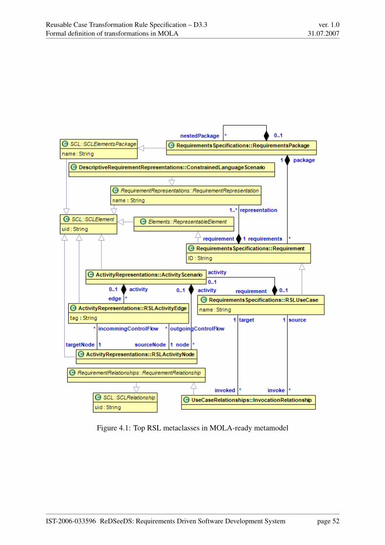
Reusable Case Transformation Rule Specification – D3.3Formal definition of transformations in MOLA
ver. 1.031.07.2007
Figure 4.1: Top RSL metaclasses in MOLA-ready metamodel
IST-2006-033596 ReDSeeDS: Requirements Driven Software Development System page 52

Reusable Case Transformation Rule Specification – D3.3Formal definition of transformations in MOLA
ver. 1.031.07.2007
Figure 4.2: Constrained language sentences for activity scenario elements
IST-2006-033596 ReDSeeDS: Requirements Driven Software Development System page 53

Reusable Case Transformation Rule Specification – D3.3Formal definition of transformations in MOLA
ver. 1.031.07.2007
Figure 4.3: Phrases and terms used in MOLA-ready metamodel
IST-2006-033596 ReDSeeDS: Requirements Driven Software Development System page 54

Reusable Case Transformation Rule Specification – D3.3Formal definition of transformations in MOLA
ver. 1.031.07.2007
Figure 4.4: Notions and their relationships
IST-2006-033596 ReDSeeDS: Requirements Driven Software Development System page 55
Reusable Case Transformation Rule Specification – D3.3Formal definition of transformations in MOLA
ver. 1.031.07.2007
Firstly, UML 2.0 is used as the base version of the metamodel. However, a relatively smallsubset is selected, containing only the basic UML notations typically used for software designspecification. This is done to make the transformation writing in MOLA manageable. Onthe other hand, this subset is sufficient for the design style, proposed for design examples inReDSeeDS.
The original UML 2.0 metamodel [Obj05] heavily uses CMOF [Obj06] elements. Thereforeit had to be transformed in a way similar to the RSL metamodel, to make it MOLA-ready. Itshould be noted, that a similar approach is used internally for several professional UML tools,including RSA by IBM Rational [SCG+05]. There UML 2.0 metamodel is reduced to EMOFand single inheritance too.
The static structure part of UML includes support for all elements typically used in class dia-grams: classes, interfaces, associations, data types etc. They are mainly contained in the Kernelpackage. The main elements for component modelling are also included (from the packageBasicComponents). Since components in the proposed ReDSeeDS software architecture areused in a quite restricted way, UML elements meant for description of deployment componentscurrently are not included. The subset of UML 2.0 elements for static structure modelling is in-cluded in a way which is semantically equivalent (instance equivalent) to the original UML 2.0metamodel. Therefore it will be possible to use the original UML 2.0 metamodel for the soft-ware case repository definition and have a complete data-preserving import/export to MOLArepository. If in the future it would occur that more UML elements would be used in trans-formations then the metamodel for the subset is easily extendable to required features, withoutthe need to modify the existing part. The only element which has been simplified with respectto the UML 2.0 standard, is a simplified stereotype concept, applicable to any UML element(without profiles and profile application, the same way as it is in Enterprise Architect and manyother tools). Figures 4.5 and 4.6 show the static structure part of the used metamodel.
The situation with behaviour description is more complicated. The main requirement is tosupport relatively complete sequence diagram notation. The solution is again based on the pre-liminary solution in deliverable 3.2.1, however, a much wider set of sequence diagram featuresare supported. The basic metamodel is close to UML 2.0 (its Interactions package), but withsome parts simplified. This is due to the fact of excessive complexity of Interactions package(already discussed in deliverable 3.2.1), which would make the transformations unnecessarycomplicated, without adding any modelling power. These excessive metamodel elements alsocould not be transferred to Enterprise Architect in a reasonable way since it uses a custom meta-model. Again, it should be noted, that the used solution is similar to that used in IBM RationalRSA [SCG+05]. A special situation is with conditional messages. All existing sequence dia-grams in ReDSeeDS examples use the traditional UML 1.4 guard notation, but not the UML
IST-2006-033596 ReDSeeDS: Requirements Driven Software Development System page 56

Reusable Case Transformation Rule Specification – D3.3Formal definition of transformations in MOLA
ver. 1.031.07.2007
Figure 4.5: The used fragment of UML Kernel package
IST-2006-033596 ReDSeeDS: Requirements Driven Software Development System page 57

Reusable Case Transformation Rule Specification – D3.3Formal definition of transformations in MOLA
ver. 1.031.07.2007
Figure 4.6: Metamodel fragment for classes
IST-2006-033596 ReDSeeDS: Requirements Driven Software Development System page 58
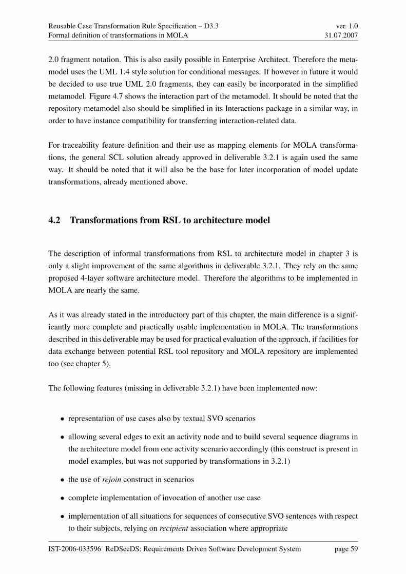
Reusable Case Transformation Rule Specification – D3.3Formal definition of transformations in MOLA
ver. 1.031.07.2007
2.0 fragment notation. This is also easily possible in Enterprise Architect. Therefore the meta-model uses the UML 1.4 style solution for conditional messages. If however in future it wouldbe decided to use true UML 2.0 fragments, they can easily be incorporated in the simplifiedmetamodel. Figure 4.7 shows the interaction part of the metamodel. It should be noted that therepository metamodel also should be simplified in its Interactions package in a similar way, inorder to have instance compatibility for transferring interaction-related data.
For traceability feature definition and their use as mapping elements for MOLA transforma-tions, the general SCL solution already approved in deliverable 3.2.1 is again used the sameway. It should be noted that it will also be the base for later incorporation of model updatetransformations, already mentioned above.
4.2 Transformations from RSL to architecture model
The description of informal transformations from RSL to architecture model in chapter 3 isonly a slight improvement of the same algorithms in deliverable 3.2.1. They rely on the sameproposed 4-layer software architecture model. Therefore the algorithms to be implemented inMOLA are nearly the same.
As it was already stated in the introductory part of this chapter, the main difference is a signif-icantly more complete and practically usable implementation in MOLA. The transformationsdescribed in this deliverable may be used for practical evaluation of the approach, if facilities fordata exchange between potential RSL tool repository and MOLA repository are implementedtoo (see chapter 5).
The following features (missing in deliverable 3.2.1) have been implemented now:
• representation of use cases also by textual SVO scenarios
• allowing several edges to exit an activity node and to build several sequence diagrams inthe architecture model from one activity scenario accordingly (this construct is present inmodel examples, but was not supported by transformations in 3.2.1)
• the use of rejoin construct in scenarios
• complete implementation of invocation of another use case
• implementation of all situations for sequences of consecutive SVO sentences with respectto their subjects, relying on recipient association where appropriate
IST-2006-033596 ReDSeeDS: Requirements Driven Software Development System page 59

Reusable Case Transformation Rule Specification – D3.3Formal definition of transformations in MOLA
ver. 1.031.07.2007
Figure 4.7: The simplified Interactions package
IST-2006-033596 ReDSeeDS: Requirements Driven Software Development System page 60

Reusable Case Transformation Rule Specification – D3.3Formal definition of transformations in MOLA
ver. 1.031.07.2007
Figure 4.8: Traceability elements used for transformations
• implementation of some missing purely technical features, such as unnecessary instancefiltering in the generated static structure.
The basic structure of the transformation is the same as in section 6.5 of deliverable 3.2.1. Inparticular, the building of static structure of the architecture model is nearly the same as inthe previous version (deliverable 3.2.1). The main extensions are in procedures building thebehaviour aspects.
MOLA procedures, which are nearly the same will be given in this deliverable without muchcomments. In general, the comments will be mainly related to algorithm details, but not MOLAconstructs. Section 6.5 of deliverable 3.2.1 already has played the role of an additional MOLAtutorial.
Similarly to the version in deliverable 3.2.1, the transformation consists of two parts - process-ing the static structure and behaviour. The static structure building is practically the same asin the previous version. It consists of procedures stc_Structure 4.10, stc_CreatePackages 4.11,stc_ApplicationLogic 4.12, stc_DataTransferObject 4.13, stc_Actors 4.14, stc_DataAccessLayer
4.15 and stc_BusinessLogic 4.16. The procedures stc_DataTransferObject and stc_DataAccess-
Layer have been modified to generate DTO and DAO objects only for those notions, which ap-pear in SVO sentences in the role of objects. The procedure stc_BusinessLogic still generatesinterfaces for all notions, but the unused ones (those which have no operations generated) aredeleted at the end of transformation (by a new procedure flt_FilterServices 4.35). The dependen-cies between the UIComponent and application logic layer interfaces are generated at the static
IST-2006-033596 ReDSeeDS: Requirements Driven Software Development System page 61

Reusable Case Transformation Rule Specification – D3.3Formal definition of transformations in MOLA
ver. 1.031.07.2007
Figure 4.9: Main procedure of the transformation
structure step. Notion relationships are now analysed in the procedure stc_DataTransferObject4.13. For each relationship a UML association is built. There currently is a problem in the RSLmetamodel, that role names cannot be provided for relationships, therefore associations will benameless now (this problem should be solved in the context of RSL tool).
The behaviour part is modified in several places due to the new functionality described above.Firstly, it is the possibility to represent a use case behaviour either by activity scenario or con-strained language scenario (if both are present, the former one is used). To implement this, themain procedure for behaviour processing - bhv_SequenceDiagramms is modified in order tosupport also text scenarios.
The processing of constrained language scenarios is similar to the processing of activity sce-narios, in the sense that an activity scenario is interpreted as a sequence of SVO or control sen-tences according to the sequence of nodes linked by edges, but a constrained language scenarioalready is such a sequence. If an edge in the activity scenario has a condition sentence, then thesame condition sentence is inserted between the normal sentences in the constrained languagescenario. A constrained language scenario can have no branching, therefore one sequence dia-gram is always generated from such a scenario. Otherwise the message building process is thesame, based on subject analysis of two consecutive SVO sentences, the processing of controlsentences is also the same.
Therefore the MOLA procedures for processing constrained language scenarios can be wellintegrated with the processing of activity scenarios. Actually, procedures are slightly redefined,so that after a common initial part processing a valid use case, the kind of its representation isfound and processed accordingly. However, the differences are only in the way how one or moreinteraction (sequence diagram) instances are created and in the way how the current and the next
IST-2006-033596 ReDSeeDS: Requirements Driven Software Development System page 62

Reusable Case Transformation Rule Specification – D3.3Formal definition of transformations in MOLA
ver. 1.031.07.2007
Figure 4.10: Main procedure for building the static structure
constrained language sentence (SVO or control sentence) is found in the scenario. The newfeature that an activity scenario may contain branching nodes, and consequently, several pathscorresponding to several interactions to be generated, is supported by a recursive procedure atthis level. The proper processing of sentences is common to both cases and actually is the sameas before.
Now, some more details of the restructured procedures.
A new important procedure for the behaviour part now is bhv_CreateUseCaseInteractions 4.19,which analyses a use case and finds, whether it has an activity scenario or constrained languagescenario and decides, which kind of processing is required (if both are available, activity isused).
In the case of activity scenario, the procedure bhv_CreateActivityScenarioInteraction 4.20 isinvoked for the given use case. It prepares the environment for a recursive traversal of thecomplete activity graph. First, the initialiser procedure bhv_CreateEmptyInteraction 4.21 isinvoked, which creates an interaction with the static lifelines valid for all situations, includingthe lifeline for the current application layer interface (for this use case). Then the recursive
IST-2006-033596 ReDSeeDS: Requirements Driven Software Development System page 63
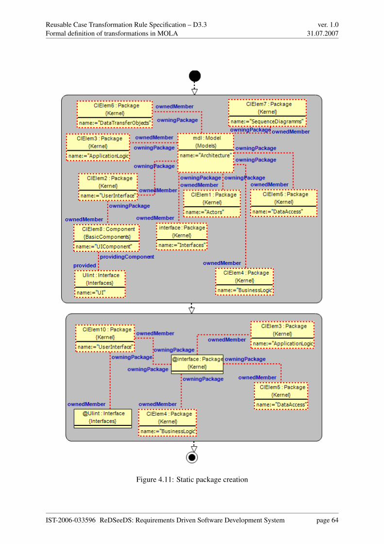
Reusable Case Transformation Rule Specification – D3.3Formal definition of transformations in MOLA
ver. 1.031.07.2007
Figure 4.11: Static package creation
IST-2006-033596 ReDSeeDS: Requirements Driven Software Development System page 64

Reusable Case Transformation Rule Specification – D3.3Formal definition of transformations in MOLA
ver. 1.031.07.2007
Figure 4.12: Procedure building the Application logic elements
IST-2006-033596 ReDSeeDS: Requirements Driven Software Development System page 65

Reusable Case Transformation Rule Specification – D3.3Formal definition of transformations in MOLA
ver. 1.031.07.2007
Figure 4.13: Procedure building the data transfer objects
IST-2006-033596 ReDSeeDS: Requirements Driven Software Development System page 66

Reusable Case Transformation Rule Specification – D3.3Formal definition of transformations in MOLA
ver. 1.031.07.2007
Figure 4.14: Procedure building UML actors
traversal is started, by invoking bhv_ActivityScenarioTraversal 4.23 on the initial node and onthe empty interaction.
The recursive procedure bhv_ActivityScenarioTraversal is capable to process one node and addthe corresponding messages to the interaction (via bhv_GenerateMessages, required actor life-lines are also created upon request). Then, if only one edge exits the node, the next node is foundand the same procedure invoked recursively on this node and the same interaction. If there is abranch node with several edges exiting, a loop is organised, which for every exit creates a newcopy of the interaction and invokes the same procedure on this copy and the appropriate node.The tag on the branch is stored, in order to build the correct name of the interaction (currentlythe name of the last branch is used as a suffix to the use case name). If a final node (or rejoin
edge) is reached, the current interaction is finalised and this recursive procedure ended. It caneasily be seen, that this way the classical graph traversal algorithm is implemented and as manyinteractions generated, as there are branches in the graph.
In the case of constrained language scenarios, the procedure bhv_CreateTextScenarioInteraction
4.32 initialises an interaction for each available scenario and invokes bhv_CreateTextInteraction-
Data 4.33 on this scenario and interaction. This procedure in turn processes language sentencesin the defined order and for each does the standard processing via bhv_GenerateMessages. The
IST-2006-033596 ReDSeeDS: Requirements Driven Software Development System page 67

Reusable Case Transformation Rule Specification – D3.3Formal definition of transformations in MOLA
ver. 1.031.07.2007
Figure 4.15: Procedure building data access objects
IST-2006-033596 ReDSeeDS: Requirements Driven Software Development System page 68

Reusable Case Transformation Rule Specification – D3.3Formal definition of transformations in MOLA
ver. 1.031.07.2007
Figure 4.16: Procedure building business logic components
IST-2006-033596 ReDSeeDS: Requirements Driven Software Development System page 69

Reusable Case Transformation Rule Specification – D3.3Formal definition of transformations in MOLA
ver. 1.031.07.2007
Figure 4.17: Procedure managing the behaviour
only difference from the activity case is that a special construct (using variables) is required tofind also the next sentence.
The processing of one sentence by bhv_GenerateMessages (taking into account also the nextone) is the same in both cases and similar to the previous version, only all situations are nowprocessed adequately. Required actor lifelines must also be added on demand, because they candiffer for several scenarios of one use case. For messages to the system itself the correspondingdependencies must also be built. But otherwise the structure of these procedures is nearly thesame as in deliverable 3.2.1 and will not be described in more detail.
IST-2006-033596 ReDSeeDS: Requirements Driven Software Development System page 70
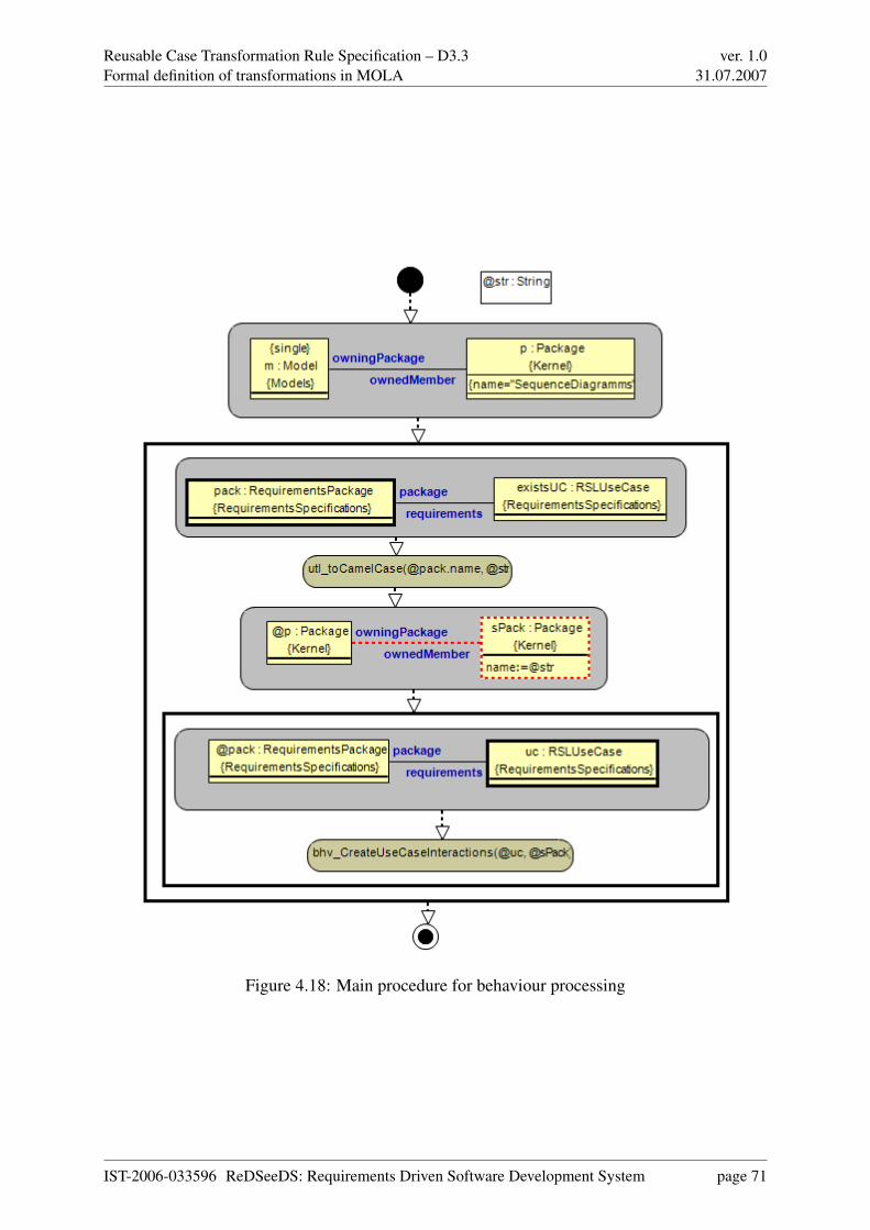
Reusable Case Transformation Rule Specification – D3.3Formal definition of transformations in MOLA
ver. 1.031.07.2007
Figure 4.18: Main procedure for behaviour processing
IST-2006-033596 ReDSeeDS: Requirements Driven Software Development System page 71

Reusable Case Transformation Rule Specification – D3.3Formal definition of transformations in MOLA
ver. 1.031.07.2007
Figure 4.19: Procedure distinguishing scenario kinds
IST-2006-033596 ReDSeeDS: Requirements Driven Software Development System page 72
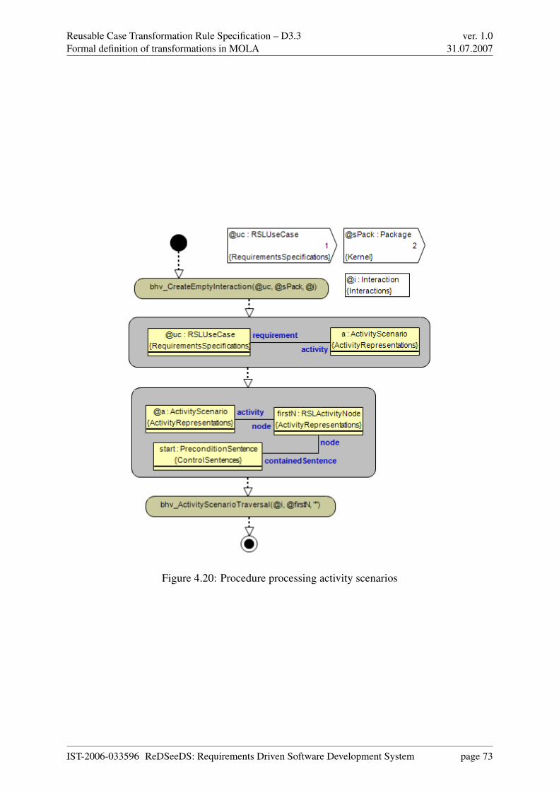
Reusable Case Transformation Rule Specification – D3.3Formal definition of transformations in MOLA
ver. 1.031.07.2007
Figure 4.20: Procedure processing activity scenarios
IST-2006-033596 ReDSeeDS: Requirements Driven Software Development System page 73

Reusable Case Transformation Rule Specification – D3.3Formal definition of transformations in MOLA
ver. 1.031.07.2007
Figure 4.21: Initialiser procedure for activity graph traversing
IST-2006-033596 ReDSeeDS: Requirements Driven Software Development System page 74
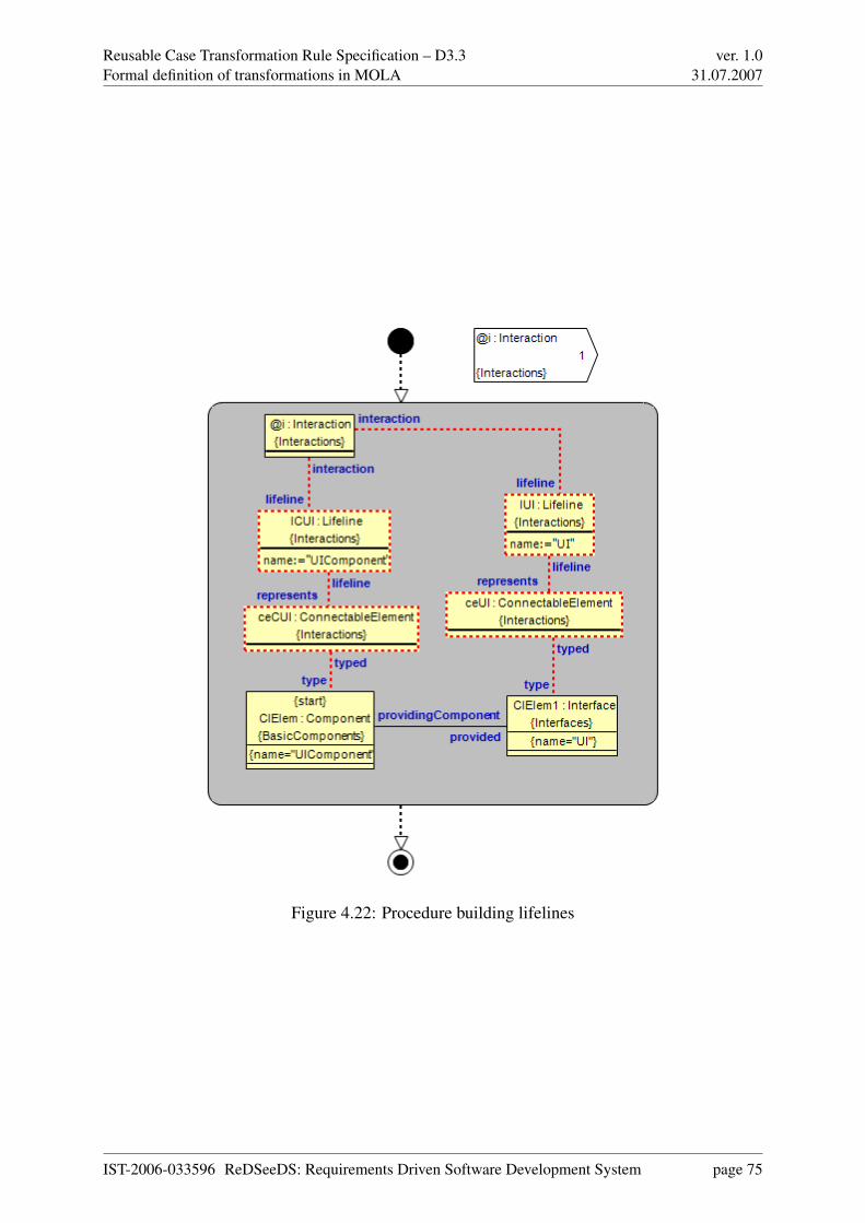
Reusable Case Transformation Rule Specification – D3.3Formal definition of transformations in MOLA
ver. 1.031.07.2007
Figure 4.22: Procedure building lifelines
IST-2006-033596 ReDSeeDS: Requirements Driven Software Development System page 75
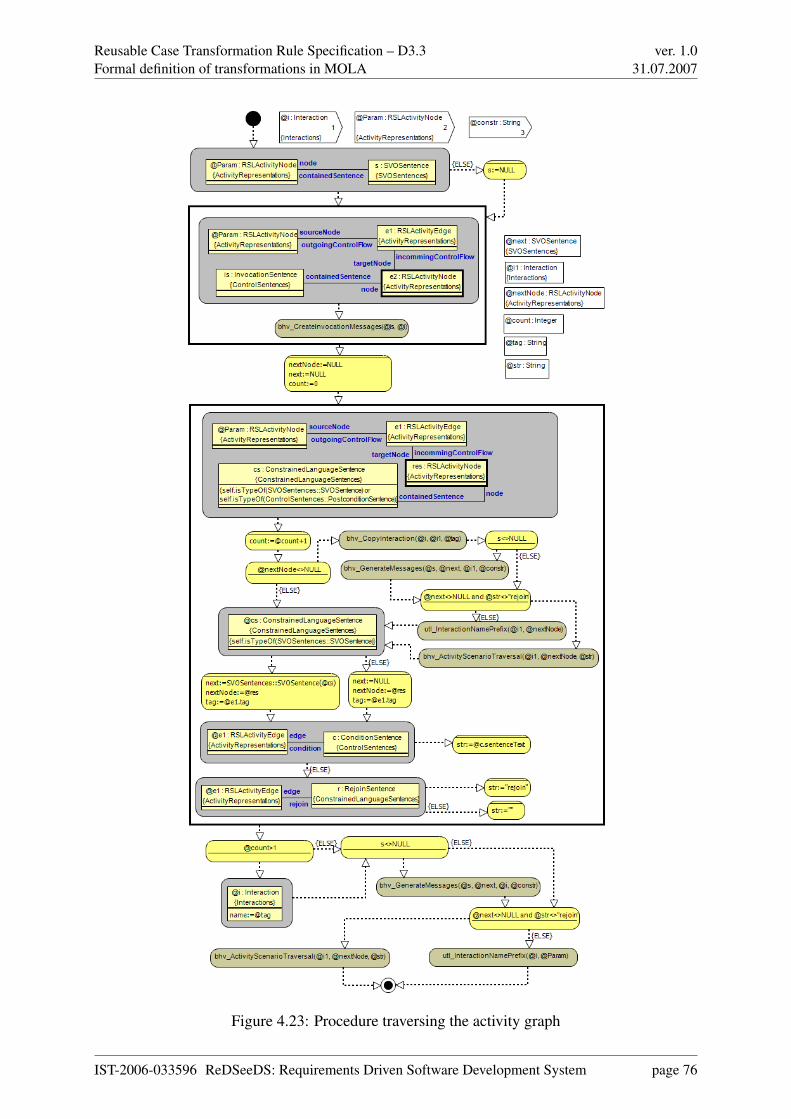
Reusable Case Transformation Rule Specification – D3.3Formal definition of transformations in MOLA
ver. 1.031.07.2007
Figure 4.23: Procedure traversing the activity graph
IST-2006-033596 ReDSeeDS: Requirements Driven Software Development System page 76

Reusable Case Transformation Rule Specification – D3.3Formal definition of transformations in MOLA
ver. 1.031.07.2007
Figure 4.24: Procedure processing invocation messages
IST-2006-033596 ReDSeeDS: Requirements Driven Software Development System page 77
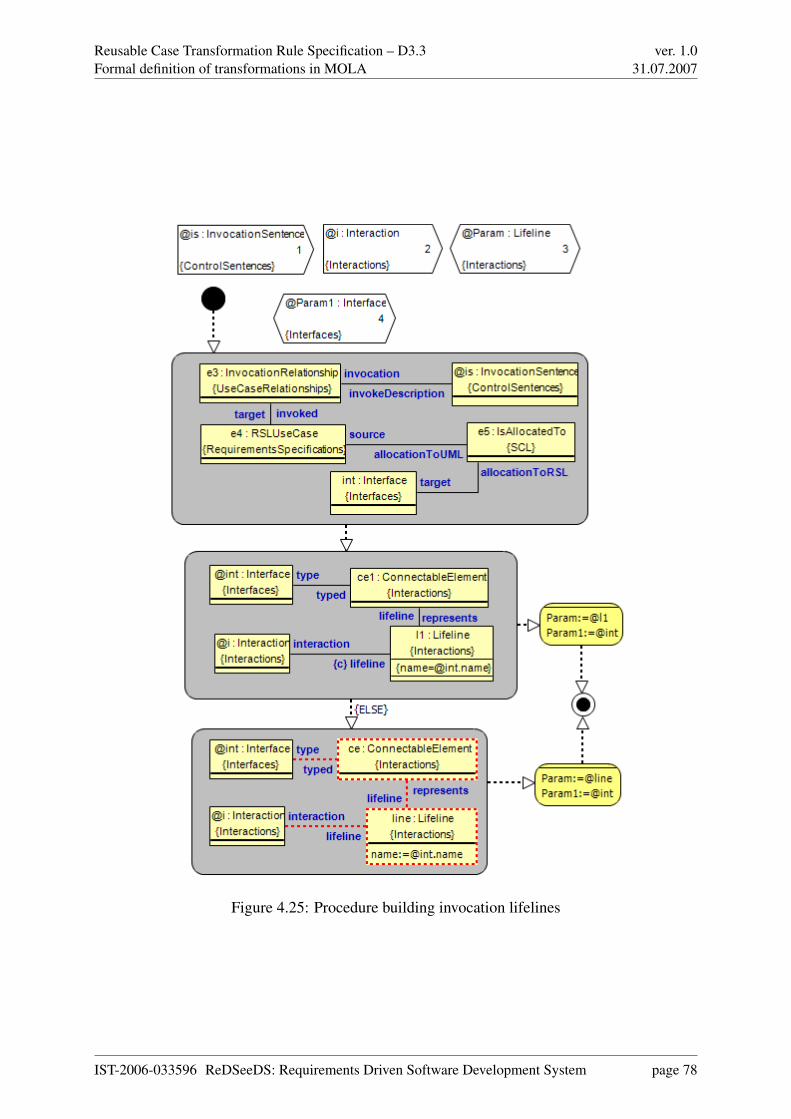
Reusable Case Transformation Rule Specification – D3.3Formal definition of transformations in MOLA
ver. 1.031.07.2007
Figure 4.25: Procedure building invocation lifelines
IST-2006-033596 ReDSeeDS: Requirements Driven Software Development System page 78

Reusable Case Transformation Rule Specification – D3.3Formal definition of transformations in MOLA
ver. 1.031.07.2007
Figure 4.26: Procedure distinguishing message kinds
IST-2006-033596 ReDSeeDS: Requirements Driven Software Development System page 79
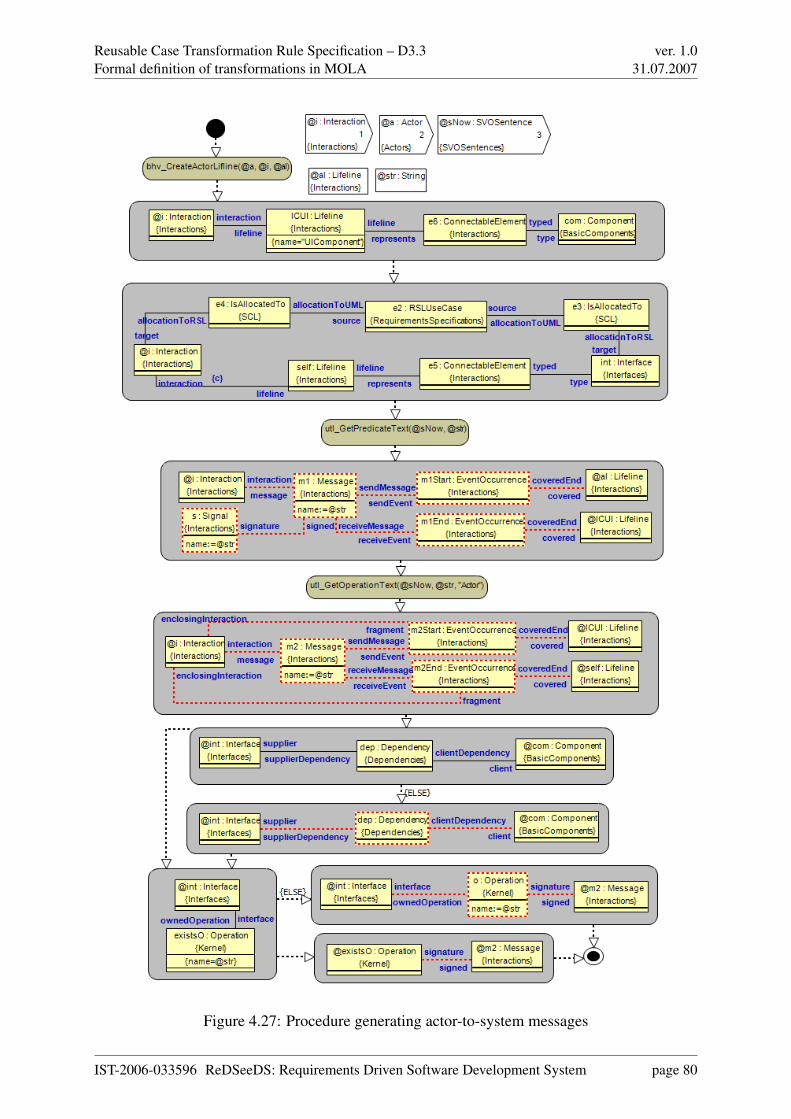
Reusable Case Transformation Rule Specification – D3.3Formal definition of transformations in MOLA
ver. 1.031.07.2007
Figure 4.27: Procedure generating actor-to-system messages
IST-2006-033596 ReDSeeDS: Requirements Driven Software Development System page 80

Reusable Case Transformation Rule Specification – D3.3Formal definition of transformations in MOLA
ver. 1.031.07.2007
Figure 4.28: Procedure generating lifeline
IST-2006-033596 ReDSeeDS: Requirements Driven Software Development System page 81
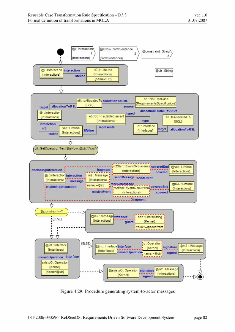
Reusable Case Transformation Rule Specification – D3.3Formal definition of transformations in MOLA
ver. 1.031.07.2007
Figure 4.29: Procedure generating system-to-actor messages
IST-2006-033596 ReDSeeDS: Requirements Driven Software Development System page 82

Reusable Case Transformation Rule Specification – D3.3Formal definition of transformations in MOLA
ver. 1.031.07.2007
Figure 4.30: Procedure generating system-to-system messages
IST-2006-033596 ReDSeeDS: Requirements Driven Software Development System page 83
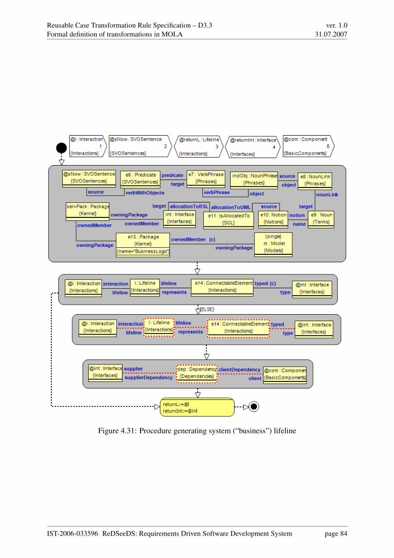
Reusable Case Transformation Rule Specification – D3.3Formal definition of transformations in MOLA
ver. 1.031.07.2007
Figure 4.31: Procedure generating system (“business”) lifeline
IST-2006-033596 ReDSeeDS: Requirements Driven Software Development System page 84

Reusable Case Transformation Rule Specification – D3.3Formal definition of transformations in MOLA
ver. 1.031.07.2007
Figure 4.32: Procedure initialising interaction for constrained language scenario
IST-2006-033596 ReDSeeDS: Requirements Driven Software Development System page 85

Reusable Case Transformation Rule Specification – D3.3Formal definition of transformations in MOLA
ver. 1.031.07.2007
Figure 4.33: Procedure processing constrained language scenarios
IST-2006-033596 ReDSeeDS: Requirements Driven Software Development System page 86

Reusable Case Transformation Rule Specification – D3.3Formal definition of transformations in MOLA
ver. 1.031.07.2007
Figure 4.34: Main procedure for behaviour processing
IST-2006-033596 ReDSeeDS: Requirements Driven Software Development System page 87

Reusable Case Transformation Rule Specification – D3.3Formal definition of transformations in MOLA
ver. 1.031.07.2007
Figure 4.35: Procedure for deletion of unused interfaces
IST-2006-033596 ReDSeeDS: Requirements Driven Software Development System page 88
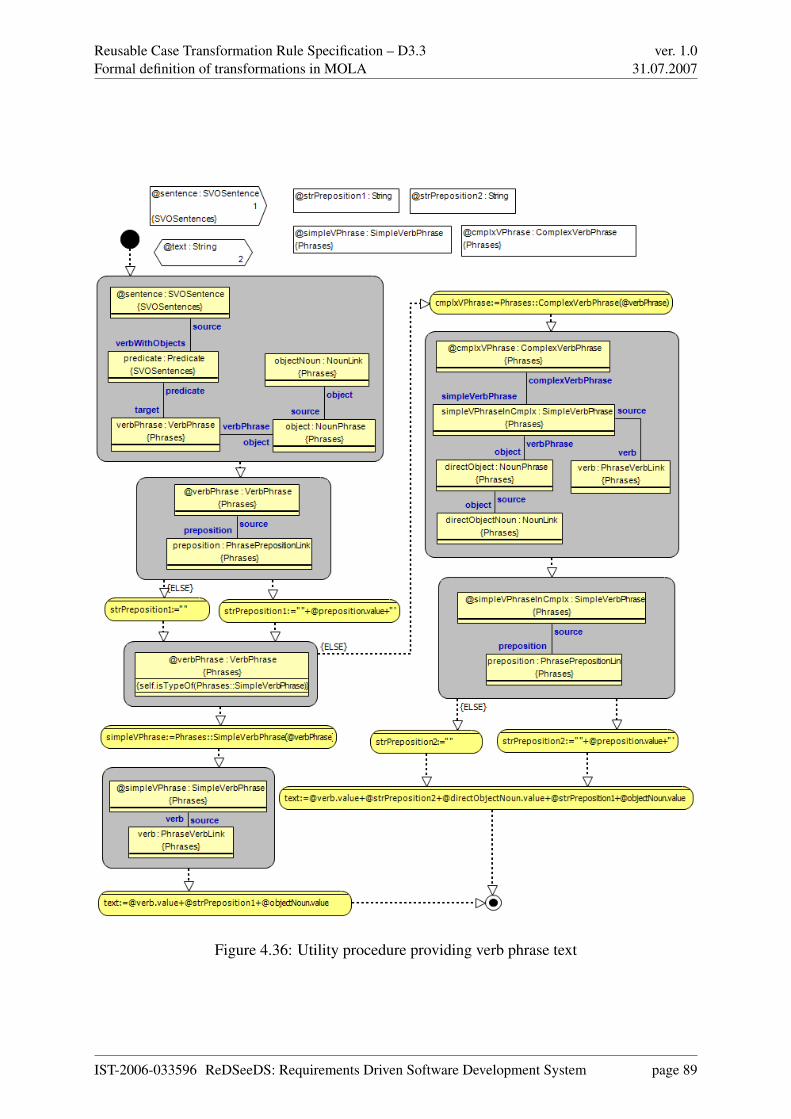
Reusable Case Transformation Rule Specification – D3.3Formal definition of transformations in MOLA
ver. 1.031.07.2007
Figure 4.36: Utility procedure providing verb phrase text
IST-2006-033596 ReDSeeDS: Requirements Driven Software Development System page 89
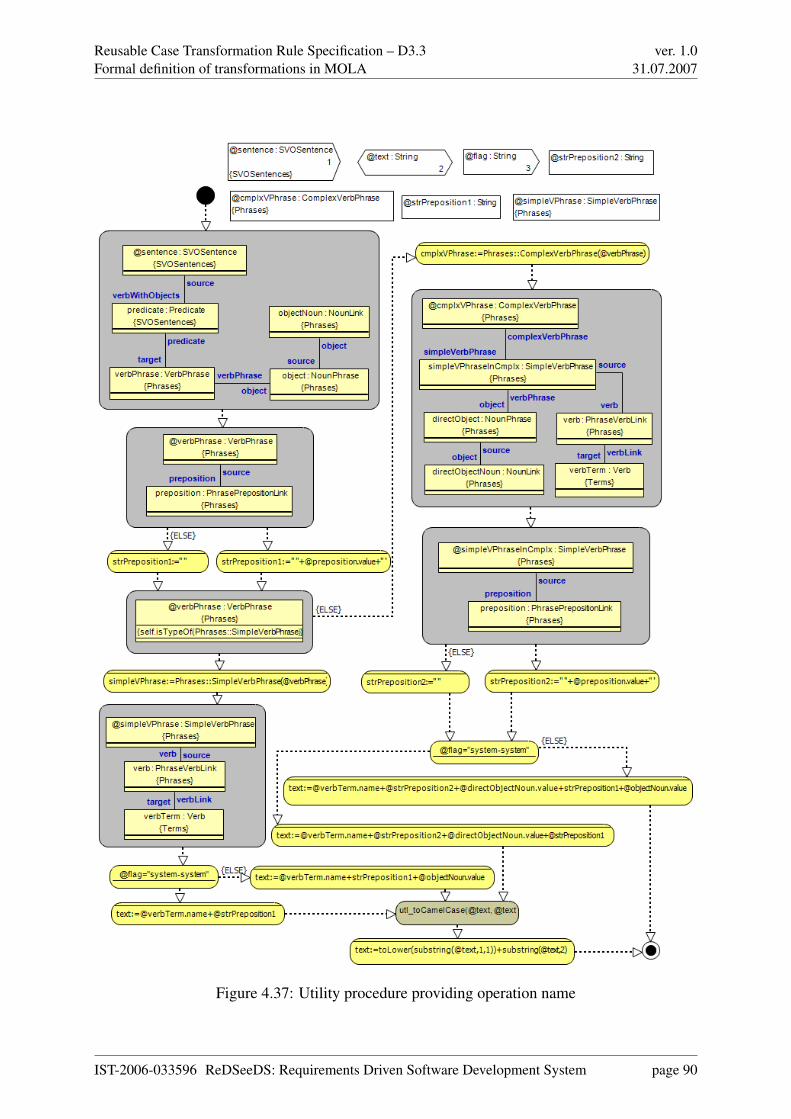
Reusable Case Transformation Rule Specification – D3.3Formal definition of transformations in MOLA
ver. 1.031.07.2007
Figure 4.37: Utility procedure providing operation name
IST-2006-033596 ReDSeeDS: Requirements Driven Software Development System page 90

Reusable Case Transformation Rule Specification – D3.3Formal definition of transformations in MOLA
ver. 1.031.07.2007
Figure 4.38: Utility procedure converting string to UpperCamelCase
IST-2006-033596 ReDSeeDS: Requirements Driven Software Development System page 91
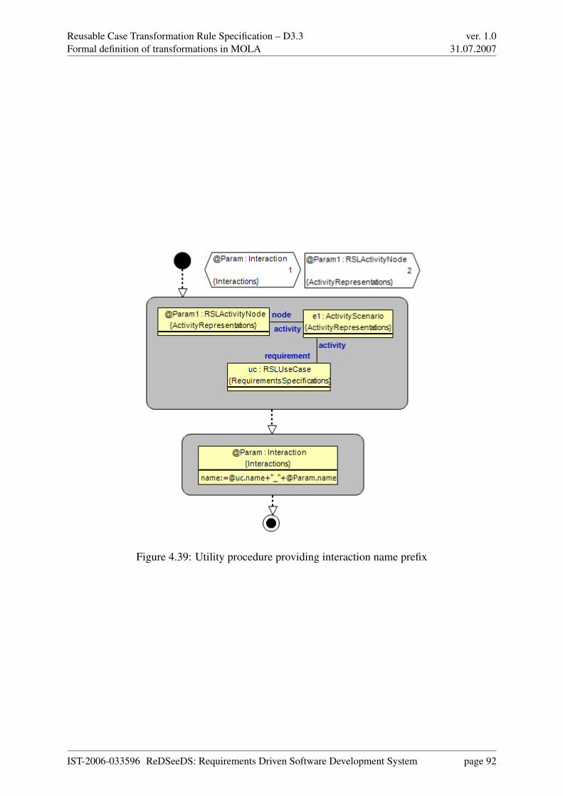
Reusable Case Transformation Rule Specification – D3.3Formal definition of transformations in MOLA
ver. 1.031.07.2007
Figure 4.39: Utility procedure providing interaction name prefix
IST-2006-033596 ReDSeeDS: Requirements Driven Software Development System page 92

Reusable Case Transformation Rule Specification – D3.3Formal definition of transformations in MOLA
ver. 1.031.07.2007
Figure 4.40: UI elements and relationships
4.3 Transformations of UI elements in RSL
This section formalises the transformation of UI elements defined in section 3.3. MOLAtransformations require metamodels restricted basically to EMOF as already mentioned in sec-tion 4.1. To be able to transform user interface requirements, a MOLA-ready version of the RSLUI metamodel part and the GUI metamodel is required. Based on these MOLA-ready sourceand target metamodels, additional MOLA transformation rules for the UI specification are de-fined. The remainder of this section is organised as follows: First, the user interface specificadditions to the MOLA-ready version of RSL are explained, Second, the target GUI metamodelis described. Third, MOLA rules which formalise the rules of section 3.3 are specified and inthe last step, MOLA rules that extend the behaviour of the UI component are defined.
4.3.1 Source and target metamodels for UI transformations
Figures 4.40 and 4.41 illustrate the MOLA-ready version of the user interface part. Since,the UI part of RSL does not rely on CMOF constructs, the RSL UI elements and RSL UIbehaviour representation packages have been added to the MOLA-ready RSL version withoutmodifications. Only missing association role names had to be added to make them accessiblein the MOLA tool.
For the target metamodel we stick to the MOLA-ready UML version. The UML profile mech-anism is used to describe target GUI models conforming to the GUI metamodel. In detail, onlyUML stereotypes are used to specify instances of the GUI metamodel. It has to be noted that inmost projects and GUI frameworks the model-to-code transformation generates only one classfor each dialog, containing initialisation code building up the GUI structure according to the
IST-2006-033596 ReDSeeDS: Requirements Driven Software Development System page 93
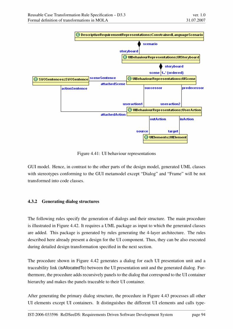
Reusable Case Transformation Rule Specification – D3.3Formal definition of transformations in MOLA
ver. 1.031.07.2007
Figure 4.41: UI behaviour representations
GUI model. Hence, in contrast to the other parts of the design model, generated UML classeswith stereotypes conforming to the GUI metamodel except “Dialog” and “Frame” will be nottransformed into code classes.
4.3.2 Generating dialog structures
The following rules specify the generation of dialogs and their structure. The main procedureis illustrated in Figure 4.42. It requires a UML package as input to which the generated classesare added. This package is generated by rules generating the 4-layer architecture. The rulesdescribed here already present a design for the UI component. Thus, they can be also executedduring detailed design transformation specified in the next section.
The procedure shown in Figure 4.42 generates a dialog for each UI presentation unit and atraceability link (isAllocatedTo) between the UI presentation unit and the generated dialog. Fur-thermore, the procedure adds recursively panels to the dialog that correspond to the UI containerhierarchy and makes the panels traceable to their UI container.
After generating the primary dialog structure, the procedure in Figure 4.43 processes all otherUI elements except UI containers. It distinguishes the different UI elements and calls type-
IST-2006-033596 ReDSeeDS: Requirements Driven Software Development System page 94

Reusable Case Transformation Rule Specification – D3.3Formal definition of transformations in MOLA
ver. 1.031.07.2007
Figure 4.42: Procedure generating GUI dialogs together with traceability links
IST-2006-033596 ReDSeeDS: Requirements Driven Software Development System page 95
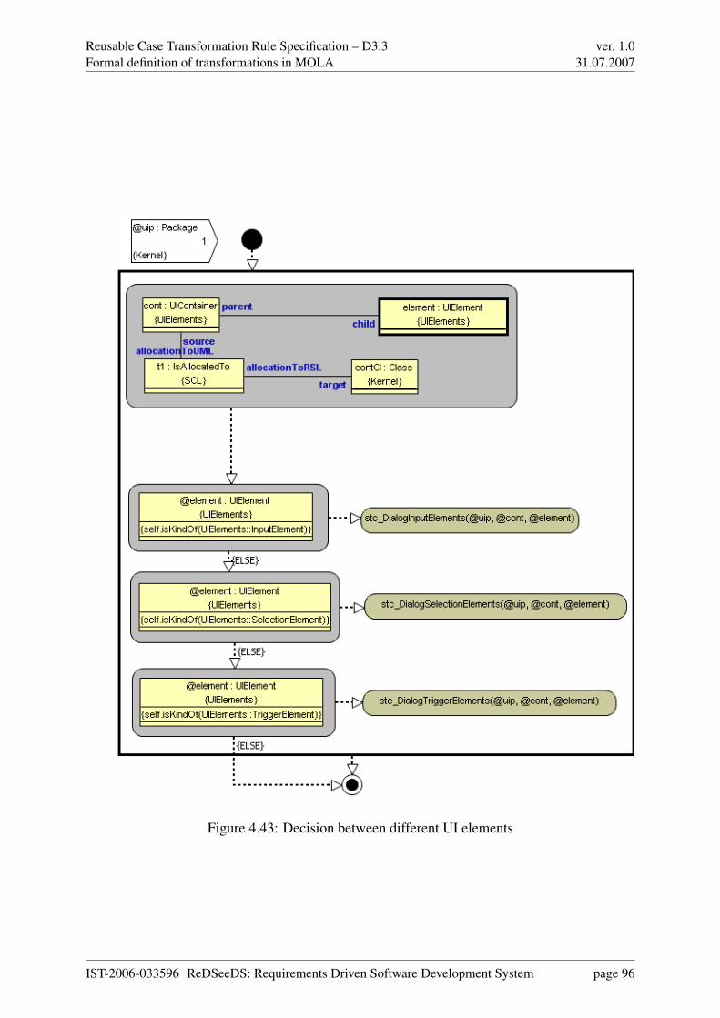
Reusable Case Transformation Rule Specification – D3.3Formal definition of transformations in MOLA
ver. 1.031.07.2007
Figure 4.43: Decision between different UI elements
IST-2006-033596 ReDSeeDS: Requirements Driven Software Development System page 96

Reusable Case Transformation Rule Specification – D3.3Formal definition of transformations in MOLA
ver. 1.031.07.2007
Figure 4.44: Procedure generating GUI elements for input UI elements
specific subprocedure and passes the element, its container and the UML package to the subprocedure.
The procedure shown in Figure 4.44 is responsible for generating text fields out of input UIelements. It simply calls the procedure responsible for generating the concrete widget withan associated label. The procedure in Figure 4.44 selects the appropriate stereotypes and handsthem over to the subprocedure which then is able to generate correctly stereotyped UML classes.
The procedure shown in Figure 4.45 is similar to the prior procedure but responsible for selec-tion UI elements. The threshold for distinguishing between radio buttons or check boxes andlist boxes on the other hand should be adapted to the needs in each project according to usabilityguidelines. This procedure distinguishes between four cases:
• Only one option is selectable and there are less or equal options than defined by thethreshold. In this case the procedure loops over all options UI elements and generates foreach option a radio button.
• Only one option is selectable and there are more options than defined by the threshold.In this this case only one list box is generated that will be populated with data duringruntime.
IST-2006-033596 ReDSeeDS: Requirements Driven Software Development System page 97

Reusable Case Transformation Rule Specification – D3.3Formal definition of transformations in MOLA
ver. 1.031.07.2007
Figure 4.45: Procedure generating GUI elements for selection UI elements
IST-2006-033596 ReDSeeDS: Requirements Driven Software Development System page 98

Reusable Case Transformation Rule Specification – D3.3Formal definition of transformations in MOLA
ver. 1.031.07.2007
• More than one option is selectable and there are less or equal options than defined by thethreshold. In this case the procedure loops over all options UI elements and generates foreach option a check box.
• More than one option is selectable and there are more options than defined by the thresh-old. In this case only one list box is generated that will be populated with data duringruntime.
The procedure shown in Figure 4.46 generates either menu items or buttons for trigger UIelements. The decision if a menu item or a button is generated depends on the attached SVOsentence. If the attached SVO sentence is an initial actor predicate, a menu item is generatedthat invokes the dialog, otherwise a button is generated.
The procedure shown in Figure 4.47 generates the actual widget and label and adds the appro-priate UML stereotype. Both widgets are added to the corresponding panel. Additionally, theprocedure establishes traceability links between the UI element and both widgets (input wid-get and label widget). After executing this procedure for all UI elements, the complete GUIstructure is generated.
To retrieve and instantiate a dialog a method is required in the UI factory. The procedure inFigure 4.48 adds a get operation for each dialog, named “get”+dialog name+“Dialog” to the UIfactory. Furthermore, the procedure establishes a dependency link between the UIFactory classand the dialog class.
The procedure in Figure 4.49 adds delegate methods for each actor predicate to the UI class thatimplements the UI interface for decoupling the GUI widgets and the application logic. Thismeans that all widgets forward their actions (actor predicates) to the UI class which then callsthe method corresponding to the actor predicate on the application logic.
IST-2006-033596 ReDSeeDS: Requirements Driven Software Development System page 99
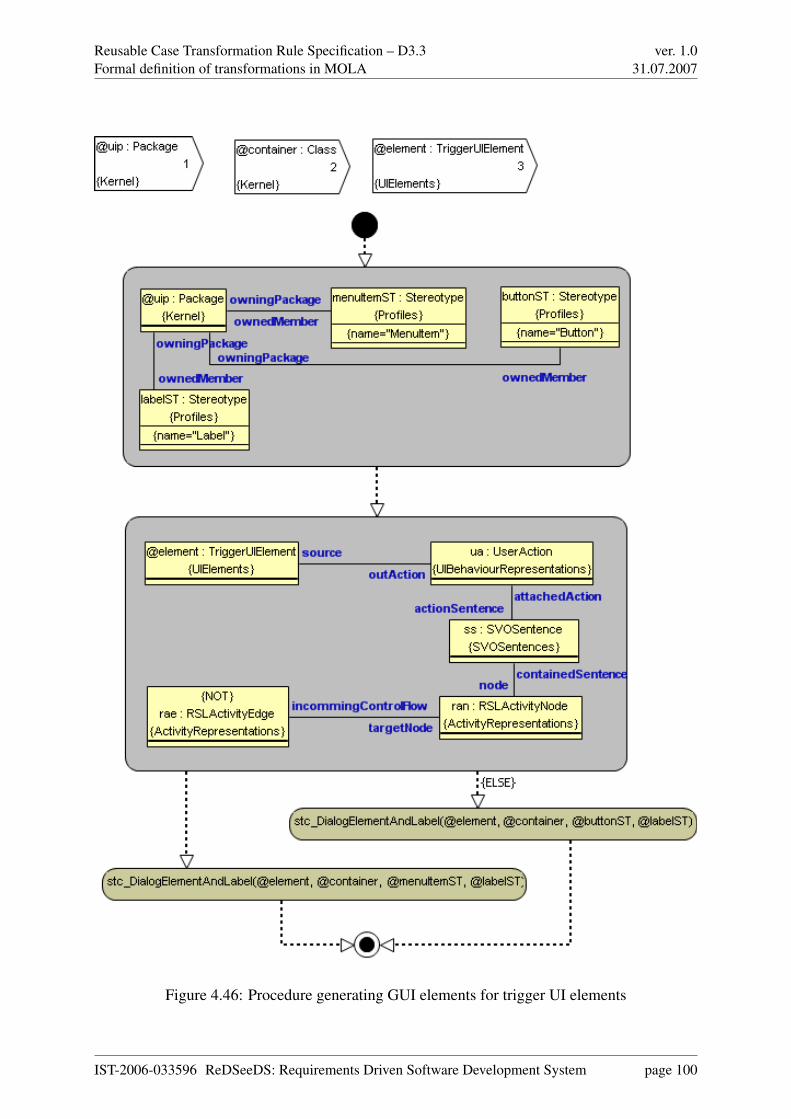
Reusable Case Transformation Rule Specification – D3.3Formal definition of transformations in MOLA
ver. 1.031.07.2007
Figure 4.46: Procedure generating GUI elements for trigger UI elements
IST-2006-033596 ReDSeeDS: Requirements Driven Software Development System page 100

Reusable Case Transformation Rule Specification – D3.3Formal definition of transformations in MOLA
ver. 1.031.07.2007
Figure 4.47: Procedure generating GUI widgets together with traceability links.
IST-2006-033596 ReDSeeDS: Requirements Driven Software Development System page 101

Reusable Case Transformation Rule Specification – D3.3Formal definition of transformations in MOLA
ver. 1.031.07.2007
Figure 4.48: Procedure generating factory methods for retrieving dialogs.
Figure 4.49: Procedure generating additional methods for the UI class.
IST-2006-033596 ReDSeeDS: Requirements Driven Software Development System page 102

Reusable Case Transformation Rule Specification – D3.3Formal definition of transformations in MOLA
ver. 1.031.07.2007
4.4 Transformations from architecture to detailed design
The algorithms for transition from the manually refined architecture model to the detailed de-sign, described in the section 3.4, are quite straightforward, if the chosen example methodologyis used. They build the static structure of detailed design model - its packages, classes and in-terfaces, with the relevant operations included. Wherever possible, the dependencies betweenelements are built, realisations between an interface and the class realising it, and a certainamount of associations. Only, because of the fact that the 4-layer architecture is to be used,the number of elements to be generated is quite large. It is clear that without an automatedtransformation support, such a model would be difficult to build correctly.
The implementation of these algorithms in MOLA to a degree would remind the structure whilebuilding for architecture, but in a much more complicate way. Initially, the general packagestructure of the detailed design model should be built, partly, in a fixed way or partly on thebasis of architecture model elements.
Then the building of classes and interfaces, their operations with full signatures and relevantdependencies can be started.
For example, to build the Application logic package, in the subpackage for the current applica-tion logic component in the architecture model, an interface and a class realisation are built foreach relevant interface in the architecture, with interface operations (with full signature) copiedin both.
Then for each architecture component a factory class is created, according to the given namingrules. Then for each class in this package (generated as described above) a factory operation isgenerated, with the name composed of the get prefix and the corresponding interface name, andwith the return type of the corresponding class. Finally, a factory class for the whole applicationlogic is built, with an operation for each component-related factory class.
Finally required dependencies are added - from component factory to interface realisationclasses and from the top factory to component factories.
Thus the algorithm implementation in MOLA to a great degree can follow the informal descrip-tion, only the correct order of instance generation must be chosen. However, taking into accountthe MOLA metamodel details, the number of instances to be generated by the transformation isquite large. And so will be the transformation program size.
IST-2006-033596 ReDSeeDS: Requirements Driven Software Development System page 103

Reusable Case Transformation Rule Specification – D3.3Formal definition of transformations in MOLA
ver. 1.031.07.2007
Figure 4.50: Main procedure for detailed design
Algorithms for other layers are similar.
According to the algorithm, associations (only between classes of different layers) are builtaccording to messages in sequence diagrams in the architecture, this occurs when a class in onelayer invokes an operation of an interface in another layer.
The described algorithm implementation in MOLA is quite straightforward and requires nocomplicated constructs, however the size of transformation procedures can be quite large. Thecomplete implementation of these transformations will be provided later, when the issue of linksto possible UML tool (Enterprise Architect) will become clearer. Namely, the necessity to seethe generated classes and interfaces as readable class diagrams may impose some modificationsto the algorithm implementation.
MOLA procedures implementing transformations from architecture to detailed design modelare shown in figures 4.50 - 4.57.
IST-2006-033596 ReDSeeDS: Requirements Driven Software Development System page 104

Reusable Case Transformation Rule Specification – D3.3Formal definition of transformations in MOLA
ver. 1.031.07.2007
Figure 4.51: Static package creation for detailed design
IST-2006-033596 ReDSeeDS: Requirements Driven Software Development System page 105
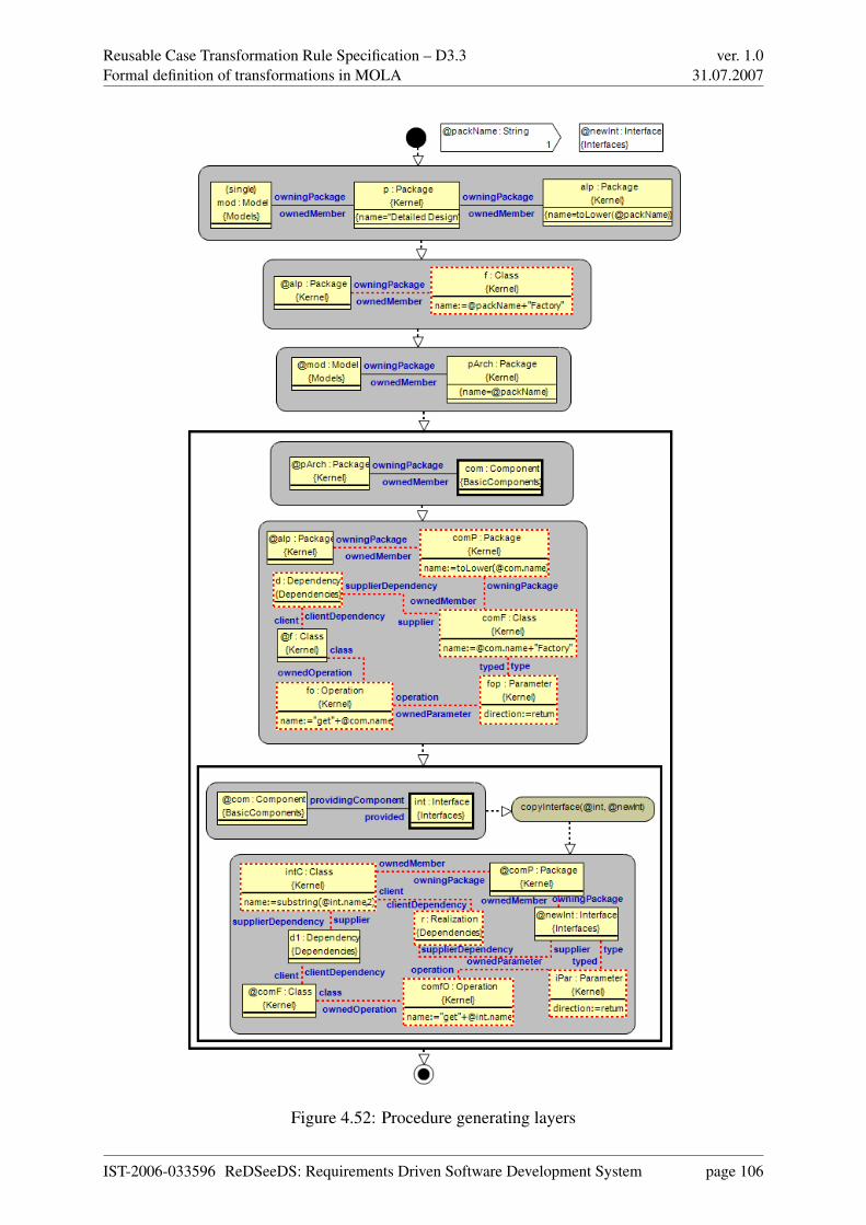
Reusable Case Transformation Rule Specification – D3.3Formal definition of transformations in MOLA
ver. 1.031.07.2007
Figure 4.52: Procedure generating layers
IST-2006-033596 ReDSeeDS: Requirements Driven Software Development System page 106

Reusable Case Transformation Rule Specification – D3.3Formal definition of transformations in MOLA
ver. 1.031.07.2007
Figure 4.53: Procedure generating data access layer
IST-2006-033596 ReDSeeDS: Requirements Driven Software Development System page 107
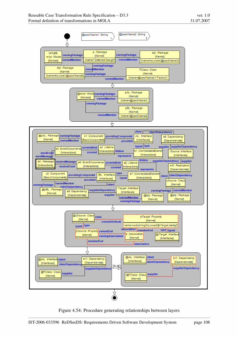
Reusable Case Transformation Rule Specification – D3.3Formal definition of transformations in MOLA
ver. 1.031.07.2007
Figure 4.54: Procedure generating relationships between layers
IST-2006-033596 ReDSeeDS: Requirements Driven Software Development System page 108

Reusable Case Transformation Rule Specification – D3.3Formal definition of transformations in MOLA
ver. 1.031.07.2007
Figure 4.55: Procedure copying data transfer objects
IST-2006-033596 ReDSeeDS: Requirements Driven Software Development System page 109
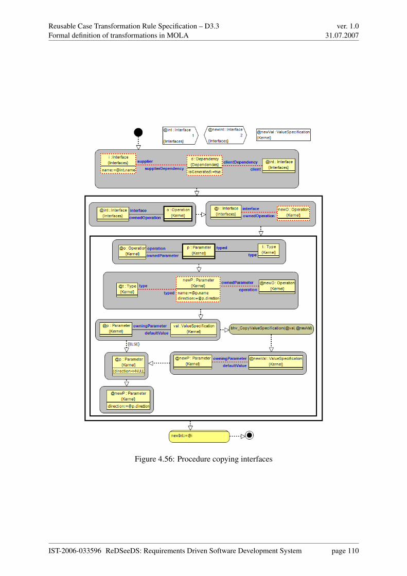
Reusable Case Transformation Rule Specification – D3.3Formal definition of transformations in MOLA
ver. 1.031.07.2007
Figure 4.56: Procedure copying interfaces
IST-2006-033596 ReDSeeDS: Requirements Driven Software Development System page 110
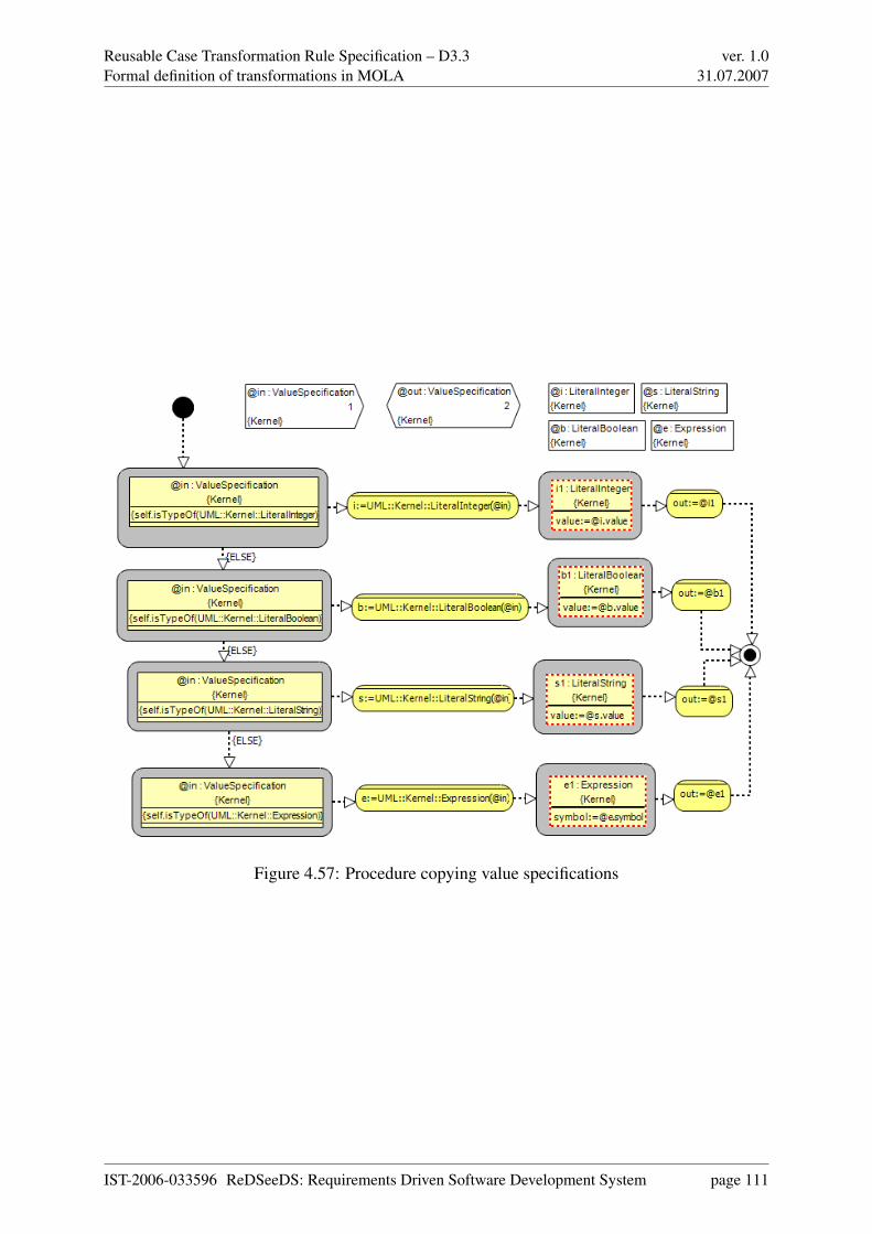
Reusable Case Transformation Rule Specification – D3.3Formal definition of transformations in MOLA
ver. 1.031.07.2007
Figure 4.57: Procedure copying value specifications
IST-2006-033596 ReDSeeDS: Requirements Driven Software Development System page 111
Reusable Case Transformation Rule Specification – D3.3Providing models to be transformed
ver. 1.031.07.2007
Chapter 5
Providing models to be transformed
The current version of MOLA can only transform models which are in the MOLA repository.The same way, the transformation results - target models are stored in the same repository. Thecurrent version of MOLA uses a specific metamodel based repository with a well defined API(in C++).
Therefore facilities have to be developed for transferring SCL models from/to repository wherethey are built using the corresponding SCL editors to/from the MOLA repository. At the givenstage no final decision has been made on SCL editors and repositories they store the models.However, one assumption has to be fixed already in this deliverable.
The models must be stored in their repositories according to the tool-ready SCL metamodel,specified already in the deliverable 3.2.1. Only in this case transformations as specified inthis deliverable make sense. If models are stored by the corresponding editors according toanother metamodel, then it is much easier for MOLA to use this metamodel as a source ortarget metamodel respectively. Especially, this refers to the RSL part of the complete SCL,where much effort has been spent on fine tuning the tool-ready RSL metamodel.
Since currently no decision has been made as to how the RSL editor in ReDSeeDS will beimplemented, a temporal solution has to be provided. A prototype RSL editor (with textual rep-resentation only) is being developed by UKo partner in ReDSeeDS, using JGraLab (describedin previous deliverables for software case repository implementation) as its repository. Thisrepository directly uses the tool-ready RSL metamodel as the repository schema. Thereforethis chapter mainly concentrates on the use of JGraLab as the repository, with which the sourceand target models are exchanged by the MOLA repository. This includes also target or source
IST-2006-033596 ReDSeeDS: Requirements Driven Software Development System page 112

Reusable Case Transformation Rule Specification – D3.3Providing models to be transformed
ver. 1.031.07.2007
models in UML 2.0, which are expected to be stored in JGraLab and then transferred to/fromEnterprise Architect.
An alternative solution could be to use Enterprise Architect as a model repository. Then UMLmodels could be stored in this repository in a more direct way. The Enterprise Architect repos-itory also has a well defined internal API for retrieving and storing models. Unfortunately,Enterprise Architect as a repository does not support an arbitrary metamodel. This metamodelhas to be very close to UML (the same classes and associations, only the attribute set may beextended). In addition, the metamodel version used is not UML 2.0, it is a custom version closeto UML 1.3 (though externally even UML 2.1 is supported by Enterprise Architect). All thisposes problems when trying to store RSL models in such a repository where this point of viewis derived from the tool-ready RSL metamodel. Besides it is the software case contained designcomponents that are required to be manipulated within Enterprise Architect by the software ar-chitect. Therefore the use of Enterprise Architect as a software case design collection repositoryis not discussed in more detail in this chapter.
This chapter describes model exchange solutions, which could be implemented with not largeefforts and consequently, could be used for experimental application of transformations to ex-ample software models in ReDSeeDS.
The clearest and simplest problem is to import a model from the JGraLab repository to theMOLA repository, with a requirement that the metamodel to be used by MOLA is a directsubset of the metamodel used as the repository schema. Namely this is the situation with thetool-ready RSL. The situation with UML 2.0 also can be reduced to this one. The proposedsolution is discussed in section 5.1. Namely this solution is the basis for some transformationtesting on real instances.
The opposite way - from MOLA to JGraLab is slightly more demanding, but still manageable.It is based on the XML-RPC exchange between the tool components. The basic principles of itare described in section 5.2.
Other subsections discuss some other issues related to model exchange between repositories.
One more issue is how to exchange UML models between JGraLab (where they are placed bytransformations in MOLA) and Enterprise Architect. Currently experiments show that this taskis solvable, but specific solutions to a great degree depend on the chosen architecture of theReDSeeDS tool in general. Therefore this issue is delayed to Workpackage 5.
IST-2006-033596 ReDSeeDS: Requirements Driven Software Development System page 113

Reusable Case Transformation Rule Specification – D3.3Providing models to be transformed
ver. 1.031.07.2007
In the conclusion one remark should be provided. It is feasible to build a new version of MOLAwithin ReDSeeDS, which would directly use JGraLab as it runtime repository (certainly, thisMOLA implementation would be Java based instead of C++ for the current one). Then transfor-mations could be executed directly within the JGraLab repository. Another gain would be to getrid of the single inheritance restriction in MOLA MOF, the EMOF restriction would still apply.Since this solution is more effort demanding, it could be provided only within the workpackage5, and not for the first evaluations of transformation technology in ReDSeeDS.
5.1 Obtaining source models for transformations from JGraLab
This section describes a relatively easy implementable solution, how models from JGraLabrepository can be transferred to MOLA repository, in order to be used as source models fortransformations. Certainly, the metamodel used in MOLA during transformation developmentmust be a direct subset of the metamodel used as the repository schema. However, it is feasiblealso to have more metamodel elements in MOLA, simply they will not get any instances.
JGraLab repository is based on TGraphs as its metamodel formalism (see deliverable 3.1, sec-tion 6.3). Currently a new simpler mapping between EMOF-based metamodel elements andTGraphs has been defined. Each metamodel class corresponds to a VertexClass in TGraphs.Each association corresponds to an EdgeClass (or CompositionClass). Class attributes corre-spond to VertexClass attributes, attributes of EdgeClass (having no counterpart in EMOF) arenot used directly. Because of this simplified mapping model exchange has become much sim-pler.
The instance import algorithm is quite straightforward. It has access to the corresponding meta-model definitions both in MOLA and JGraLab repositories. The algorithm scans classes inthe MOLA metamodel. For each such class a VertexClass with the same (qualified) name issought in JGraLab. If it is found, all vertices (i.e., instances) of that class are transformedinto instances of the corresponding class in the MOLA repository (attribute correspondence isstraightforward). Then for each association in the MOLA metamodel the corresponding Edge-Class in JGraLab is sought on the basis of role names (EdgeClass names are generated andhave no direct counterpart in MOLA), it is permitted to use more role names in MOLA thanin JGraLab. For each found correspondence all instances of the EdgeClass are converted intocorresponding association instances (links) in MOLA.
The only technical problem in the implementation of this algorithm is that JGraLab is in Javaand MOLA repository has a C++ API. The import application (GraMol) will be developed in
IST-2006-033596 ReDSeeDS: Requirements Driven Software Development System page 114

Reusable Case Transformation Rule Specification – D3.3Providing models to be transformed
ver. 1.031.07.2007
Java, and it will access both repositories simultaneously. The JNI (Java Native Interface) willbe used for accessing the MOLA repository with its C++ API. The application will directlyimplement the above mentioned algorithm.
MOLA transformation execution, most probably, will be invoked from the ReDSeeDS engine.Then the described import application (GraMol) will be invoked as a prologue to this execution.
This simple execution schema is oriented towards the first experimental applications of transfor-mations in ReDSeeDS. Therefore the client-server aspect is completely ignored in this simpleapproach.
For storing the transformation results (target model) back to the JGraLab repository, however,a different technology, most probably, will be used. This technology is described in the nextsection.
5.2 Storing transformation results to JGraLab
This section explores the possibilities of storing the results of transformations performed by acompiled MOLA transformation to JGraLab. Basically, there are two concepts which can bethought of. First, the MOLA transformation could store the resulting model only to its internalrepository. A separate converter tool would then have to read this model from the MOLA repos-itory, convert it to the JGraLab format and then store it to the JGraLab repository. The othernotion requires the MOLA transformation to publish the operations which must be executedon the source model in order to transform it to the target model (certainly, these operations areexecuted also inside the MOLA repository in the standard way, this is required to ensure thestandard MOLA execution logic). These operations could then be immediately applied to theJGraLab repository.
Closely connected to the two approaches described above is the question of how to access theJGraLab repository. Besides the Java API offering the full range of graph and schema creation,manipulation and traversal, JGraLab also provides an XML-RPC (XML Remote Procedure Call)[Win99] interface for remote access. Although, at present, it only features the calling of proce-dures to handle graphs, this is sufficient to map the results of transformations to the repository.
The following description is based on the assumption that in both issues, the second option ischosen, i.e. the MOLA transformation directly changes the JGraLab repository via the XML-RPC interface. This alternative seems to be advantageous due to two aspects: While JGraLab is
IST-2006-033596 ReDSeeDS: Requirements Driven Software Development System page 115

Reusable Case Transformation Rule Specification – D3.3Providing models to be transformed
ver. 1.031.07.2007
implemented in Java, MOLA is written in C++. Consequently, a converter tool would need toemploy JNI (Java Native Interface) [Lia99] in order to bridge this gap. However, the main prob-lem with the converter approach is that no clear semantics can be defined for instance updateand delete semantics in JGraLab. It should be noted, that there are no such semantics problemsfor instance import to MOLA. Furthermore, a current idea concerning the architecture of theReDSeeDS engine is to run the fact repository, i.e. JGraLab, on a server while the transforma-tion engine resides on the client side. The realisation of this architecture requires a technologyto remotely access JGraLab’s methods.
The next section goes more into the details of the XML-RPC interface on the server side(JGraLab). Afterwards, the client side (MOLA) is described.
5.2.1 JGraLab XML-RPC server
The server-side XML-RPC interface of JGraLab is based on the Java Servlet technology. Graphsand their elements, i.e. vertices and edges are referenced by using numerical handles or IDsreturned by the server.
The following list shows a selection of JGraLab features which can be invoked by a client:
• creation, loading and saving of graphs
• creation and deletion of vertices and edges
• getting and setting of attribute values of vertices and edges
• traversal of graphs
As it can be seen, these features cover all the operations needed to perform changes as requiredby a model transformation: creation, deletion and modification of graph elements. The lattercorresponds to the modification of attribute values.
5.2.2 MOLA transformation XML-RPC client
As it was already noted, to perform this simultaneous modification of JGraLab repository, theMOLA transformation for each repository related operation (instance creation, instance dele-tion, attribute modification, link creation/deletion) must perform the same operation on the
IST-2006-033596 ReDSeeDS: Requirements Driven Software Development System page 116

Reusable Case Transformation Rule Specification – D3.3Providing models to be transformed
ver. 1.031.07.2007
JGraLab repository. Since initially the MOLA repository was a copy of part of JGraLab repos-itory, this synchronous execution of operations would guarantee, that at the transformation ex-ecution end also the JGraLab repository would contain the target model.
Certainly, to achieve this, the MOLA compiler has to be extended to perform these duplicate op-erations on the JGraLab repository, whenever there is such an operation in the native repository.The size of extended code seems not to be very large.
These special operations will invoke the relevant JGraLab API operations via XML-RPC. Onlythe graph (i.e., instance) modification operations are required in this approach. All these opera-tions are supported by the XML-RPC client.
The main gain from this approach would be the completely safe instance management semanticsin JGraLab.
5.3 Storing of traceability information
The transformation of models requires traceability links to be created between correspondingelements of the source model and the target model. For example, a Requirement specified byan RSL model is connected to the architectural UML construct supposed to realise the Re-
quirement. This connection is established by a traceability link of type IsAllocatedTo. A designmodel having its source in an architectural model is linked to the latter via an UML::Dependency.Generated program code can be traced back to its source model by Implements links. See De-liverable 3.2.1 for more details on different traceability link types.
The JGraLab repository holds a graph representation of artifacts contained in a Software Case.Thus, it is also well suited to store information on traceability links as additional edges inter-connecting the representation of related artifacts. Since the transformation engine is supposedto create instances of traceability links along with the target model, these links could be storedto the repository according to the concepts described in section 5.2.
IST-2006-033596 ReDSeeDS: Requirements Driven Software Development System page 117

Reusable Case Transformation Rule Specification – D3.3Conclusion
ver. 1.031.07.2007
Chapter 6
Conclusion
This document describes transformations to be used for software case development in ReD-SeeDS. Possible generation of the initial version of the next model from the previous one iscovered for the basic transition steps in software case development.
This document offers one specific 4-layer architecture and methodology elements related to it,where the part of the next model to be generated automatically is sufficiently high. If a softwarecase is being developed according to this architecture then the document provides ready-to-usetransformations from requirements in RSL to architecture model in a subset of UML and fromarchitecture to detailed design, as well as transformations for building user interface elements.Both the informal transformation algorithms and their implementation in MOLA language areprovided in the document. Therefore the transformations can be used as is or easily be modifiedif the software case requires some modifications to the architecture.
The transition step from the detailed design model to code is not covered in this document sincethis requires some basic solutions in ReDSeeDS tool set to be made beforehand.
The document discusses also basic principles, which should be used for obtaining models tobe transformed from the software case repository and placing the transformation results backto this repository. Currently only the version where models are taken from a JGraLab basedrepository and placed back to such a repository is discussed. This version could be imple-mented relatively easily. However, the final solution in this area also depends on some generalarchitecture principles for the ReDSeeDS tool set.
IST-2006-033596 ReDSeeDS: Requirements Driven Software Development System page 118
Reusable Case Transformation Rule Specification – D3.3Bibliography
ver. 1.031.07.2007
Bibliography
[KSC+07] Audris Kalnins, Agris Sostaks, Edgars Celms, Elina Kalnina, Albert Ambroziewicz,Jacek Bojarski, Wiktor Nowakowski, Tomasz Straszak, Volker Riediger, HannesSchwarz, Daniel Bildhauer, Sevan Kavaldjian, Roman Popp, and Jurgen Falb.Reuse-oriented modelling and transformation language definition. Technical report,ReDSeeDS, 2007.
[KWW03] A G Kleppe, J B Warmer, and Bast W. MDA Explained, The Model Driven Archi-
tecture: Practice and Promise. Addison-Wesley, Boston, 2003.
[Lia99] Sheng Liang. The Java Native Interface. Programmer’s Guide and Specification.Addison-Wesley, 1999.
[MM03] Joaquin Miller and Jishnu Mukerji, editors. MDA Guide Version 1.0.1, omg/03-06-
01. Object Management Group, 2003.
[Obj05] Object Management Group. Unified Modeling Language: Superstructure, version
2.0, formal/05-07-04, 2005.
[Obj06] Object Management Group. Meta Object Facility Core Specification, version 2.0,
formal/2006-01-01, 2006.
[SCG+05] P Swithinbank, M Chessell, T Gardner, C Griffin, J Man, H Wylie, and L Yusuf.Patterns: Model-Driven Development Using IBM Rational Software Architect (IBM
Redbook SG24-7105-00). International Business Machines Corporation (IBM).,2005.
[SV06] T Stahl and M Voelter. Model-Driven Software Development (Technology, Enge-
neering, Management). John Wiley & Sons, Ltd, 2006.
[Win99] Dave Winer. XML-RPC Specification, June 1999. http://www.xmlrpc.com/spec.
IST-2006-033596 ReDSeeDS: Requirements Driven Software Development System page 119