revere 6 - biolapsa.com
TRANSCRIPT

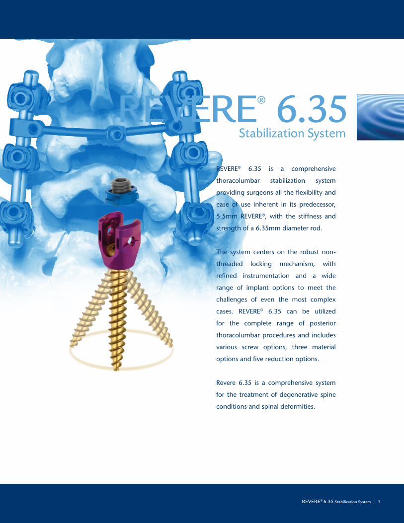
REVERE® 6.35Stabilization System
Surgical Technique

2 | Life moves uswww.globusmedical.com
At Globus, we move with a sense of urgency to deliver innovations that improve the quality of life for patients with spinal disorders. We are inspired by the needs of these patients and also the needs of the surgeons and health care providers who treat them.
This passion combined with Globus’s world class engineering transforms clinical insights into tangible spine care solutions. We are driven to provide the highest quality products to improve
the techniques and outcomes of spine surgery so patients can resume their lives as quickly as possible. We extend our reach beyond our world class implants, instrumentation, and service by partnering with researchers and educators to advance the science and knowledge of spine care.
The energy and enthusiasm each of us bring everyday to Globus is palpable. We are constantly in the pursuit of better patient care and understand that speed is critical because life cannot wait.
REVERE® 6.35 Stabilizatin System | 1
reVere® 6.35 is a comprehensive
thoracolumbar stabilization system
providing surgeons all the flexibility and
ease of use inherent in its predecessor,
5.5mm reVere®, with the stiffness and
strength of a 6.35mm diameter rod.
The system centers on the robust non-
threaded locking mechanism, with
refined instrumentation and a wide
range of implant options to meet the
challenges of even the most complex
cases. reVere® 6.35 can be utilized
for the complete range of posterior
thoracolumbar procedures and includes
various screw options, three material
options and five reduction options.
revere 6.35 is a comprehensive system
for the treatment of degenerative spine
conditions and spinal deformities.
REVERE® 6.35Stabilization System
REVERE® 6.35 Stabilization System | 1
2 | Life moves us
REVERE® 6.35Stabilization SyStEm
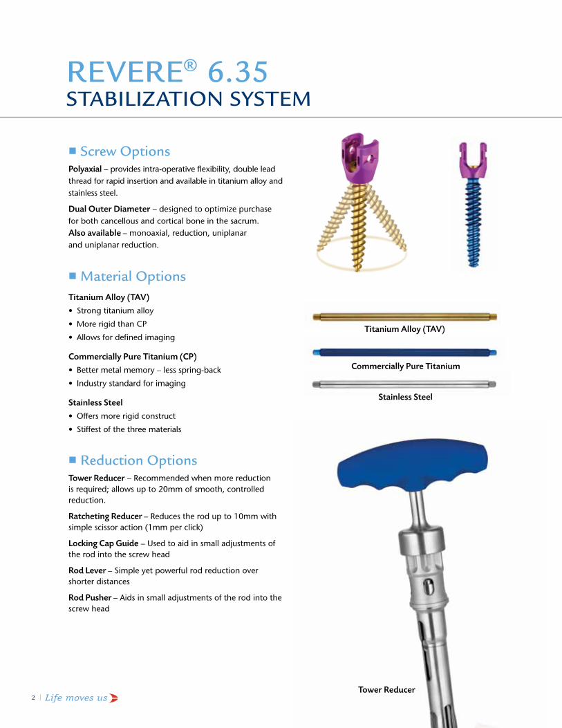
Screw optionsPolyaxial – provides intra-operative flexibility, double lead thread for rapid insertion and available in titanium alloy and stainless steel.
Dual Outer Diameter – designed to optimize purchase for both cancellous and cortical bone in the sacrum.Also available – monoaxial, reduction, uniplanar and uniplanar reduction.
material options Titanium Alloy (TAV)
• Strongtitaniumalloy
• MorerigidthanCP
• Allowsfordefinedimaging
Commercially Pure Titanium (CP)
• Bettermetalmemory–lessspring-back
• Industrystandardforimaging
Stainless Steel
• Offersmorerigidconstruct
• Stiffestofthethreematerials
Reduction optionsTower Reducer – recommended when more reduction is required; allows up to 20mm of smooth, controlled reduction.
Ratcheting Reducer – reduces the rod up to 10mm with simple scissor action (1mm per click)
Locking Cap Guide – used to aid in small adjustments of the rod into the screw head
Rod Lever – Simple yet powerful rod reduction over shorter distances
Rod Pusher – aids in small adjustments of the rod into the screw head
Titanium Alloy (TAV)
Stainless Steel
Commercially Pure Titanium
Tower Reducer

REVERE® 6.35 Stabilizatin System | 3
ImplantOverview 4
MaterialOptions 6
InstrumentOverview 7
Surgical Technique
1. approach 15
2.PolyaxialScrewInsertion 15
3. rod insertion and locking cap Delivery 18
4.CompressionorDistraction 25
5. Final construct 26
6.OptionalTechniques 27
reVere® 6.35 implant Set list 30
reVere®6.35InstrumentISetList 34
reVere® 6.35 instrument ii Set list 36
reVere®6.35DualOuterDiameterScrewImplantSetList 38
Stainless Steel reVere®6.35ImplantSetList 40
ImportantInformation 43
ContEntS
The surgical technique shown is for illustrative purposes only. The technique(s) actually employed in each case always depends on the medical judgment of the surgeon exercised before and during surgery as to the best mode of treatment for each patient. Additionally, as instruments may occasionally be updated, the instruments depicted in this Surgical Technique may not be exactly the same as the instruments currently available. Please consult with your sales representative or contact Globus directly for more information.
REVERE® implants have not been evaluated for safety and compatibility in the MR environment. They have not been tested for heating or migration in the MR environment. REVERE® implants are made from titanium alloy or commercially pure titanium, and are also available in stainless steel. Implants made from titanium alloy or commercially pure titanium have been shown to produce less artifact on CT or MRI than stainless steel implants.

4 | Life moves us
non-threaded locking Cap• non-threaded design eliminates cross-threading
• low torque locking mechanism
• 90° rotation to capture the rod
• Optimaldesigndecreasesneedforrodreduction
• Set screw pre-torqued in place to prevent any unintentional movement in shipping or handling
• allows direct placement with the hex driver for easier assembly
Screw thread• Self-tapping design
• Blunttipforbicorticalpurchase
• constant outer diameter for maximum bone purchase
• Double lead thread for rapid insertion(upto7.5mmdiameter)
• Taps are available, color-coded to screw size
Polyaxial Screws• ±30° angulation (60° total) provides
intraoperative flexibility
• low torque locking mechanism
• Double lead thread for rapid insertion (upto7.5mmdiameter)
• Screwdiameters4.5,5.0,5.5,6.5,7.5,8.5,9.0mm
• Screw lengths 25–120mm
• available in titanium alloy and stainless steel
• color-coded screws
imPlant oVERViEw
REVERE® 6.35 Stabilizatin System | 5
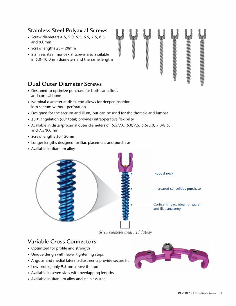
Stainless Steel Polyaxial Screws• Screwdiameters4.5,5.0,5.5,6.5,7.5,8.5,
and 9.0mm
• Screw lengths 25–120mm
• Stainless steel monoaxial screws also available in 5.0–10.0mm diameters and the same lengths
Dual outer Diameter Screws• Designed to optimize purchase for both cancellous and cortical bone
• nominal diameter at distal end allows for deeper insertion into sacrum without perforation
• Designed for the sacrum and ilium, but can be used for the thoracic and lumbar
• ±30° angulation (60° total) provides intraoperative flexibility
•Availableindistal/proximalouterdiametersof5.5/7.0,6.0/7.5,6.5/8.0,7.0/8.5,and7.5/9.0mm
• Screw lengths 30-120mm
• longer lengths designed for iliac placement and purchase
• available in titanium alloy
Variable Cross Connectors•Optimizedforprofileandstrength
• unique design with fewer tightening steps
• angular and medial-lateral adjustments provide secure fit
• low profile, only 9.5mm above the rod
• available in seven sizes with overlapping lengths
• available in titanium alloy and stainless steel
robust neck
increased cancellous purchase
cortical thread, ideal for sacral and iliac anatomy
Screw diameter measured distally
6 | Life moves us
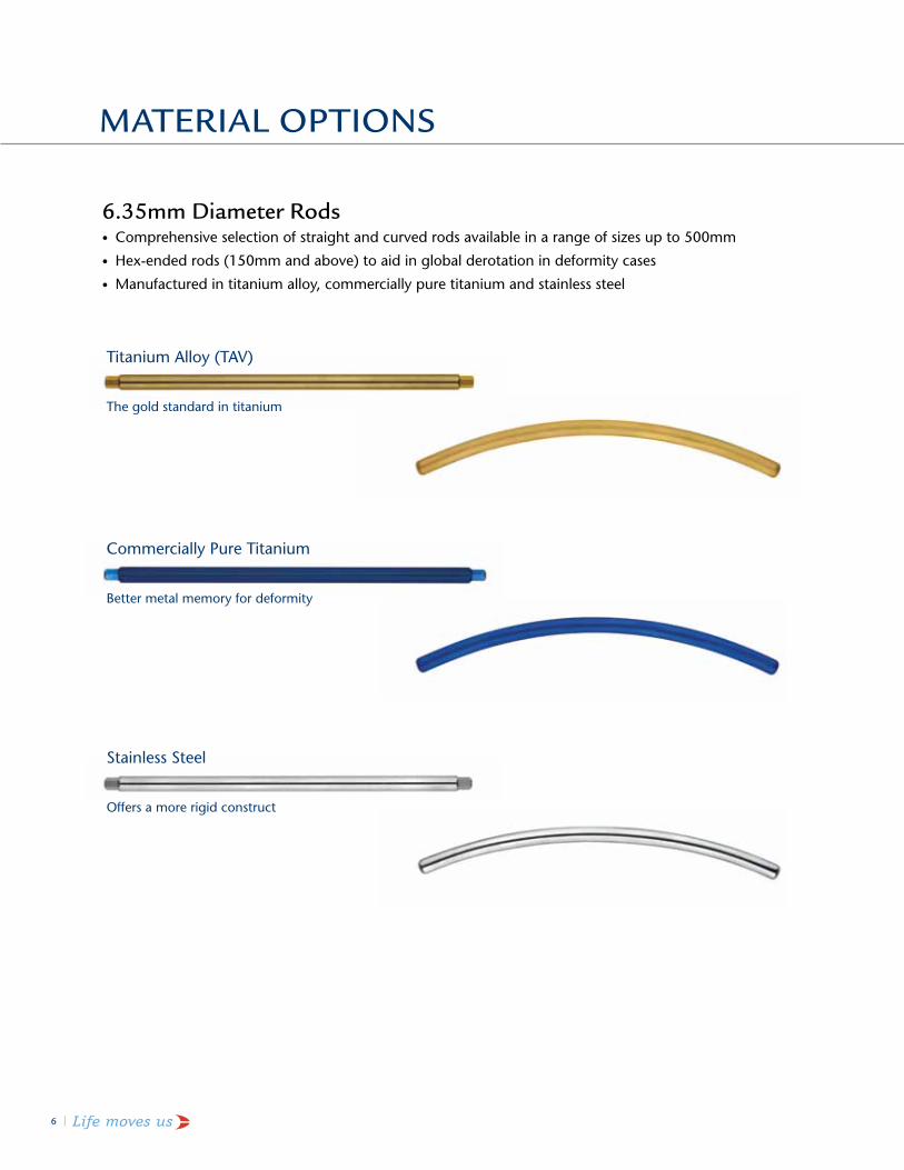
6.35mm Diameter Rods• comprehensive selection of straight and curved rods available in a range of sizes up to 500mm
• hex-ended rods (150mm and above) to aid in global derotation in deformity cases
• Manufacturedintitaniumalloy,commerciallypuretitaniumandstainlesssteel
matERial oPtionS
Titanium alloy (TaV)
The gold standard in titanium
CommerciallyPureTitanium
Bettermetalmemoryfordeformity
Stainless Steel
Offersamorerigidconstruct

REVERE® 6.35 Stabilizatin System | 7
BallTipProbe,Curved602.106
BallTipProbe,DoubleEnded624.110
PedicleProbe,Straight602.101
inStRUmEnt oVERViEw
Pedicle Preparation instruments
PedicleAwl602.104
PedicleProbe,Curved602.102
PedicleProbe,Thoracic602.109
BallTipProbe602.105
8 | Life moves us
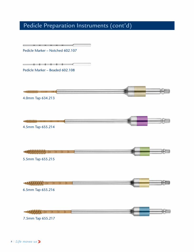
6.5mm Tap 655.216
7.5mmTap655.217
Pedicle Preparation instruments (cont’d)
PedicleMarker–Notched602.107
PedicleMarker–Beaded602.108
4.0mmTap634.213
4.5mmTap655.214
5.5mm Tap 655.215

REVERE® 6.35 Stabilizatin System | 9
QuickDisconnect1/4"Non-Ratcheting,LargeSportHandle634.406(alternativehandle)
3.5mmHexDriverSelf-RetainingShaft,1/4"Connection634.408
BallEndHexDriverShaft630.411
Screw insertion instruments
QuickRelease1/4",Ratchet,StraightHandle630.407
3.5mmHexDriverRigidShaft634.703
6.35HoldingSleeveAssembly634.704
Rigid Driver Assembly (Assembled: Disassemble for cleaning)
10 | Life moves us
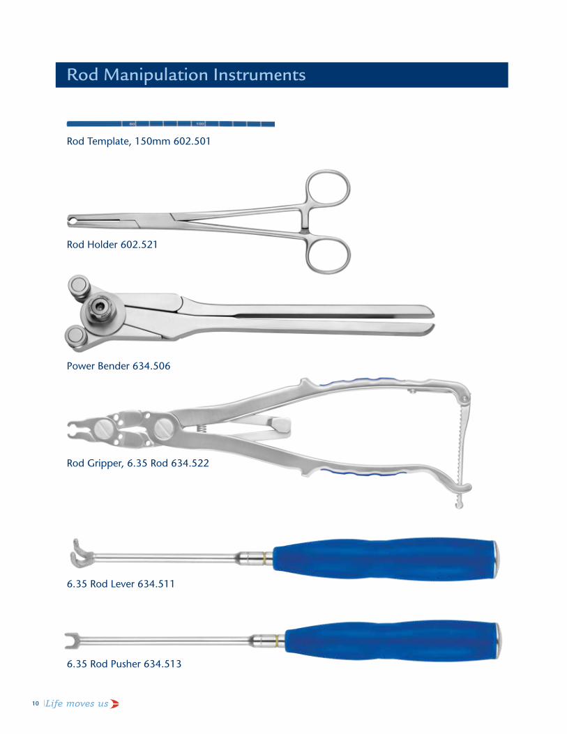
rod Template, 150mm 602.501
rod holder 602.521
PowerBender634.506
RodGripper,6.35Rod634.522
6.35RodLever634.511
6.35RodPusher634.513
Rod manipulation instruments
REVERE® 6.35 Stabilizatin System | 11
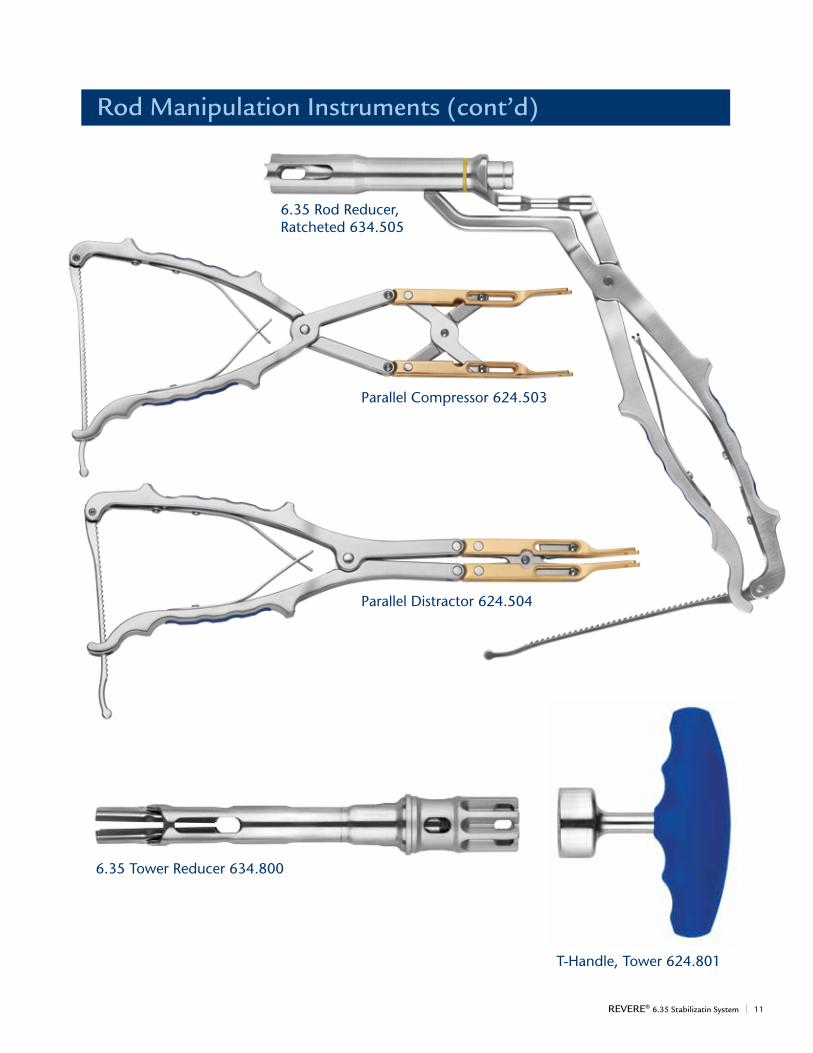
6.35 rod reducer, Ratcheted634.505
Rod manipulation instruments (cont’d)
ParallelCompressor624.503
ParallelDistractor624.504
T-Handle,Tower624.801
6.35TowerReducer634.800

12 | Life moves us
6.35FinalTighteningCounterTorque634.603
6.35LockingCapGuide634.602
Screw locking instruments
3.5mmHexScrewdriverShaft,1/4"Connection634.405
6.35LockingCapDriver634.601
QuickDisconnect1/4",3.5mmRatcheting TorqueLimitingT-Handle634.604
REVERE® 6.35 Stabilizatin System | 13
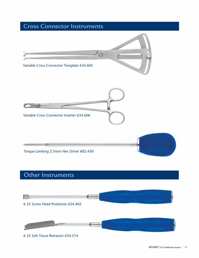
VariableCrossConnectorTemplate634.605
Cross Connector instruments
VariableCrossConnectorInserter634.606
TorqueLimiting2.5mmHexDriver602.430
6.35ScrewHeadPositioner634.402
6.35SoftTissueRetractor634.514
other instruments

14 | Life moves us
8.5mm Tap 655.218
9.0mmTap634.219
additionally available instruments
3.5mmHexDriver,1/4",Connect,Long634.706
rod cutter 602.508
3.5mm Torque limiting Driver, ratcheting, 1/4"Connect,SS634.611–tobeusedwith634.405or634.408
QuickRelease1/4",Ratchet,T-Handle630.401–tobeusedwith634.405or634.408orallthetaps

REVERE® 6.35 Stabilizatin System | 15
REVERE® 6.35 SURgiCal tEChniqUE
approach
The patient is placed under anesthesia and positioned prone. The operative area is carefully cleaned and an incision is made at the appropriate level(s). Lateral C-arm fluoroscopy or other radiographic methods can be utilized throughout surgery to ensure correct screw placement.
There are various techniques for pedicle screw and rod insertion. For the purposes of this technique guide, a Wiltse paramedial approach and building of an L4-L5-S1 construct are shown.
Note: Please refer to product insert for complete description, indications, contraindications and warnings.
1Step
Preparingpediclepathway
2Step PolyaxialScrewInsertion
Pedicle Preparation
Locate pedicles and remove bone and/or soft tissue as needed using standard instruments.
Use the Pedicle Awl to perforate the pedicle cortex.
Use a Pedicle Probe to open the pedicle pathway. Demarcations every 10mm on the probe indicate the depth of the pathway and help determine proper screw length.
Use a Ball Tip Probe to verify that the walls of the prepared pedicle pathway are not violated. Demarcations every 10mm on the probe indicate the depth of the pathway and can also help determine proper screw length.
REVERE® 6.35 pedicle screws are self-tapping, however pedicles may be tapped if desired. Insert the Tap of the desired diameter into the Quick Release Ratchet Handle. Tap the pedicle to the determined depth.

16 | Life moves us
Screwdriver Assembly
Select the appropriate pedicle screw diameter and length. Assemble the 3.5mm Hex Screwdriver Rigid Shaft to the Quick Release Ratchet Handle. Slide the Holding Sleeve Assembly over the shaft. Turn the knurled knob until the indication line (groove) on the shaft is visible. Insert the screwdriver into the screw body. Once engaged, turn the knurled knob counterclockwise (LOCK) until the screw is firmly in place, holding the threaded portion of the screw straight to engage the hex. The thread on the driver should not be visible when the hex is fully engaged.
To disengage, turn the ratcheting mechanism on the handle to neutral or reverse. Turn the knurled knob clockwise (UNLOCK) until the line on the shaft is visible. Pull up and disengage the driver from the screw.
Load the screw onto a screwdriver, as shown above. Verify the size by checking the length and diameter markings on the screw head, in addition to using the gauge provided in the implant tray.
Alternatively, the Self-Retaining 3.5mm Hex Screwdriver Shaft attached to the Quick Disconnect Non-Ratcheting Handle may be used for screw insertion. Simply insert the hex tip into the hexagonal screw head until the indicator line on the shaft is flush (see arrow below).
reVere® 6.35 polyaxial screw loaded onto screwdriver
indication line (groove) on shaft Screw engaged
Self-retaining 3.5mm hex Screwdriver Shaft attached to the quick Disconnect non-ratcheting handle
Self-retaining 3.5mm hex Screwdriver Shaft attached to the quick release ratchet handle

REVERE® 6.35 Stabilizatin System | 17
Inserting Screws
Drive the screws into the prepared pedicles. When complete, remove the screwdriver from the screw head. If using the 3.5mm Hex Screwdriver Rigid Shaft and Holding Sleeve, rotate the knurled knob clockwise in the UNLOCK direction to disengage the screwdriver and remove. If the screws need to be removed or repositioned, the 3.5mm Self-Retaining Screwdriver may be used.
Screw insertion
Screws inserted
Rigid Driver Assembly
18 | Life moves us
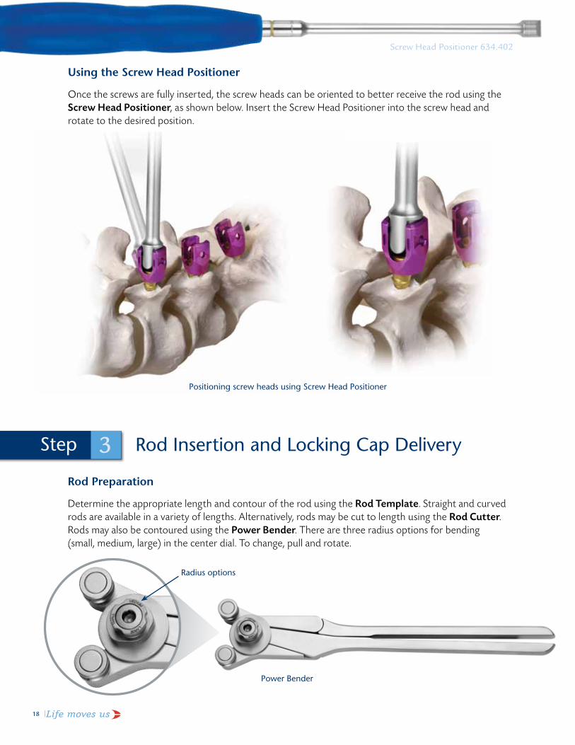
Using the Screw Head Positioner
Once the screws are fully inserted, the screw heads can be oriented to better receive the rod using the Screw Head Positioner, as shown below. Insert the Screw Head Positioner into the screw head and rotate to the desired position.
PositioningscrewheadsusingScrewHeadPositioner
radius options
rod insertion and locking cap Delivery
Rod Preparation
Determine the appropriate length and contour of the rod using the Rod Template. Straight and curved rods are available in a variety of lengths. Alternatively, rods may be cut to length using the Rod Cutter. Rods may also be contoured using the Power Bender. There are three radius options for bending (small, medium, large) in the center dial. To change, pull and rotate.
3Step
PowerBender
Screw Head Positioner 634.402
radius options
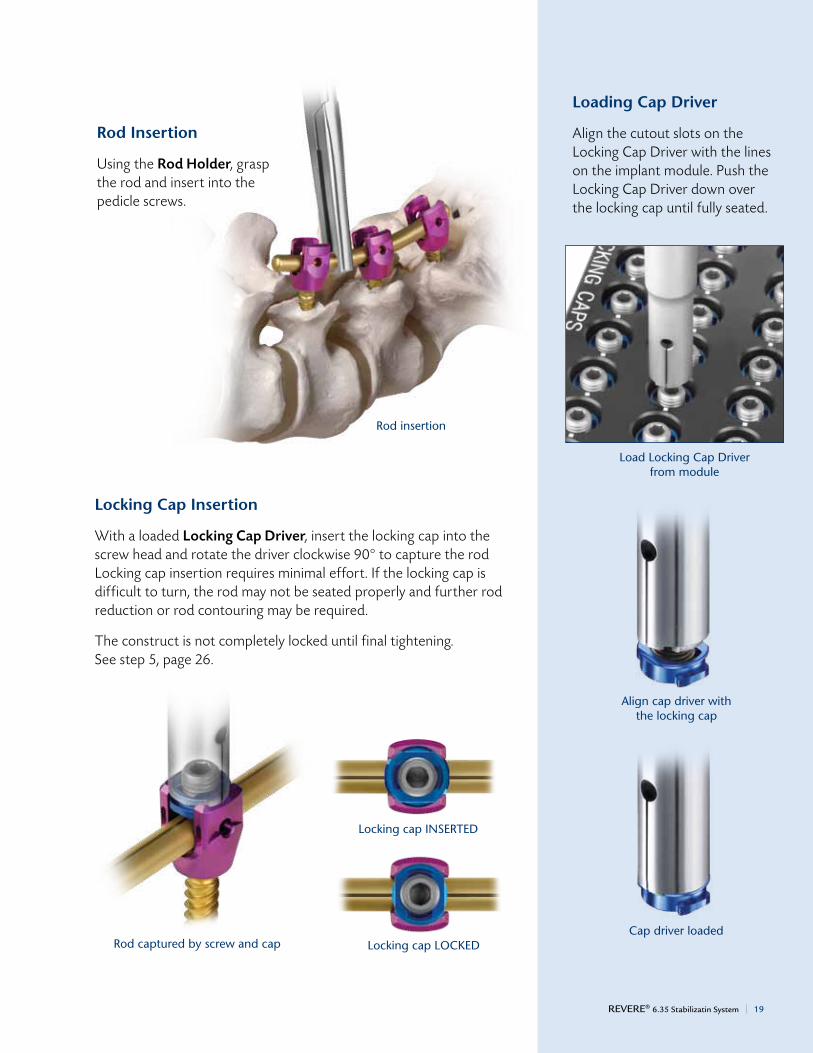
Rod Insertion
Using the Rod Holder, grasp the rod and insert into the pedicle screws.
rod insertion
Locking Cap Insertion
With a loaded Locking Cap Driver, insert the locking cap into the screw head and rotate the driver clockwise 90° to capture the rod Locking cap insertion requires minimal effort. If the locking cap is difficult to turn, the rod may not be seated properly and further rod reduction or rod contouring may be required.
The construct is not completely locked until final tightening. See step 5, page 26.
rod captured by screw and cap
locking cap inSerTeD
LockingcapLOCKED
Loading Cap Driver
Align the cutout slots on the Locking Cap Driver with the lines on the implant module. Push the Locking Cap Driver down over the locking cap until fully seated.
load locking cap Driver from module
align cap driver with the locking cap
cap driver loaded
REVERE® 6.35 Stabilizatin System | 19

20 | Life moves us
Using the Locking Cap Guide Locking Cap Guide
The Locking Cap Guide is used to aid in small adjustments of the rod into the screw head and acts as a guide for the Locking Cap Driver. Place the Locking Cap Guide over the rod and screw head, and apply downward pressure. The Locking Cap Guide handle can be adjusted to a parallel position, as shown at left.
To adjust the Locking Cap Guide to a parallel position, loosen the set screw using the Torque Limiting 2.5mm Hex Driver and rotate the handle on the Locking Cap Guide 90°. Secure the handle by tightening the set screw.
locking cap insertion through locking cap guide
Set Screw
UsingtheRodPusherusing the rod holder
If greater visualization is desired, the Rod Holder, Rod Gripper or Rod Pusher may be used. The Rod Pusher aids in small adjustments of the rod into the screw head. Place the Rod Pusher over the rod and apply downward pressure. Once the rod is seated within the screw head, load the Locking Cap Driver and install the locking cap, as shown.
90°

REVERE® 6.35 Stabilizatin System | 21
Rod Reduction
The REVERE® 6.35 system has five options for rod reduction:
• LockingCapGuide• RodPusher• RodLever• RatchetedRodReducer• TowerReducer
The rod reduction instruments are designed to seat the rod into the screw head, not to bend the rod. Ensure that the rod is properly contoured prior to reduction.
Option 1: Locking Cap Guide
The Locking Cap Guide may be used for rod reduction. The instrument aids in small adjustments of the rod into the screw head.
Option 2: Rod Pusher
The Rod Pusher aids in direct manual reduction of the rod. This instrument aids in small adjustments of the rod into the screw head.
locking Cap guide
Option2:RodreductionusingtheRodPusher
Rod Pusher
Option1:RodreductionusingtheLockingCapGuide

22 | Life moves us
Option 3: Rod Lever
The Rod Lever can be used to maneuver the rod into position. This instrument is useful when the rod is slightly above the screw. Slide the Rod Lever into the reduction slots on the screw head. Lever the rod down, sliding it into the screw head.
rod reduction using the rod lever
Rod lever

REVERE® 6.35 Stabilizatin System | 23
Option 4: Ratcheted Rod Reducer
The Ratcheted Rod Reducer provides up to 10mm of reduction (1mm per click) and can be used to reduce the rod into position. Ensure it is fully open, then place the Ratcheted Rod Reducer squarely over the screw head and push down until it is fully seated. Compress the handles to engage and reduce the rod. The groove on the proximal end of the internal shaft is exposed when the rod is fully reduced. The Locking Cap Driver is inserted through the Reducer.
rod reduction using the ratcheted rod reducer
Ratcheted Rod Reducer

Option 5: Tower Reducer
The Tower Reducer provides up to 20mm of continuous reduction and can be used to reduce the rod into position.
Ensure the reducer is in the starting position by fully backing it up counter clockwise until stop (do not over-tighten). Place the Tower Reducer squarely over the screw head and push down until it is completely flush with the screw head. Turn the reducer clockwise and continue until the horizontal etchings align, as shown at right.
Utilize the T-Handle to reduce, if preferred.
Insert the loaded Cap Driver into the Tower Reducer.
Rotate the Cap Driver 90° clockwise to engage the locking cap.
Provisionally tighten the locking cap set screw.
Remove the Cap Driver and Tower Reducer by turning counterclockwise until stop .
Note: The Tower Reducer provides strong rod reduction (with a range up to 20mm).
24 | Life moves us
Tower reducer
reduction using Tower reducer
etch line indicates rod is fully reduced
REVERE® 6.35 Stabilizatin System | 25
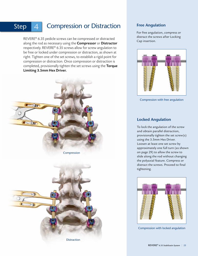
compression or Distraction
REVERE® 6.35 pedicle screws can be compressed or distracted along the rod as necessary using the Compressor or Distractor respectively. REVERE® 6.35 screws allow for screw angulation to be free or locked under compression or distraction, as shown at right. Tighten one of the set screws, to establish a rigid point for compression or distraction. Once compression or distraction is completed, provisionally tighten the set screws using the Torque Limiting 3.5mm Hex Driver.
4Step Free Angulation
For free angulation, compress or distract the screws after Locking Cap insertion.
Locked Angulation
To lock the angulation of the screw and obtain parallel distraction, provisionally tighten the set screw(s) using the 3.5mm Hex Driver. Loosen at least one set screw by approximately one full turn (as shown on page 29) to allow the screw to slide along the rod without changing the polyaxial feature. Compress or distract the screws. Proceed to final tightening.
Distraction
compression with free angulation
compression with locked angulation
compression
26 | Life moves us
Final construct
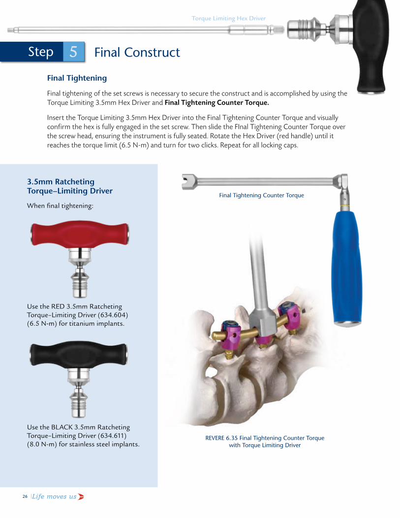
Final Tightening
Final tightening of the set screws is necessary to secure the construct and is accomplished by using the Torque Limiting 3.5mm Hex Driver and Final Tightening Counter Torque.
Insert the Torque Limiting 3.5mm Hex Driver into the Final Tightening Counter Torque and visually confirm the hex is fully engaged in the set screw. Then slide the FInal Tightening Counter Torque over the screw head, ensuring the instrument is fully seated. Rotate the Hex Driver (red handle) until it reaches the torque limit (6.5 N-m) and turn for two clicks. Repeat for all locking caps.
Final Tightening counter Torque
reVere 6.35 Final Tightening counter Torque with Torque limiting Driver
torque limiting hex Driver
3.5mm Ratcheting Torque–Limiting Driver
When final tightening:
Use the RED 3.5mm Ratcheting Torque–Limiting Driver (634.604) (6.5 N-m) for titanium implants.
Use the BLACK 3.5mm Ratcheting Torque–Limiting Driver (634.611) (8.0 N-m) for stainless steel implants.
5Step

REVERE® 6.35 Stabilizatin System | 27
OptionalTechniques
Variable Cross Connector Insertion
To enhance construct stability, the Variable Cross Connector may be used as a transverse connector between two rods. The Variable Cross Connector Template can be used to estimate the length between the two rods.
Using Variable Cross Connector Template
The Variable Cross Connector Template may be used to estimate the length between the two rods, as shown.
•Unlock the thumb screw of the Variable Cross Connector Template.
•Place the template between the rods at the desired level and lock the thumb screw.
•Read the span distance from the template handle indicated at the arrow.
• Use this measurement to determine the appropriate Variable Cross Connector size ranges, as shown below.
6Step
Variable cross connector Template
Variable cross connector Template (end view indicating 69mm)
using Variable cross connector Template

28 | Life moves us
Variable Cross Connector Insertion (cont'd)
Use the Variable Cross Connector Inserter to grasp the desired cross connector. Position the connector between the rods and provisionally tighten the set screws on the rods through the Variable Cross Connector Inserter. Adjust the connector position and provisionally tighten the set screws on the rods. Then tighten the center set screw. Final tighten the set screws bearing on the rods using the same Torque Limiting 2.5mm Hex Driver (2.5 N-m).
inserting the Variable cross connector
Final reVere® 6.35 construct

REVERE® 6.35 Stabilizatin System | 29
Implant Removal
To remove a screw, begin by removing the locking cap. Insert the Self-Retaining 3.5mm Hex Screwdriver into the set screw of the locking cap. Rotate the Hex Driver counterclockwise until the set screw fully backs off from the rod and the locking cap becomes disengaged from the screw head (90° turn). Repeat for all desired screws. Remove the rod using the Rod Holder. Remove each screw using the self-retaining 3.5mm Hex Screwdriver or Ball End Hex Driver, if required. If the set screw strips, the locking cap can be released using the Locking Cap Driver (turning 90º counterclockwise).
removing the locking cap Pullingouttherod
removing a screw using the Self-retaining hex Screwdriver
removing a screw using theBallEndHexDriver

30 | Life moves us
REVERE® 6.35 imPlant SEt
1
1
2
3
4
5

REVERE® 6.35 Stabilizatin System | 31
REVERE® 6.35 implant Set list 934.901
reVere®6.35PolyaxialPedicleScrews
*items highlighted in gray are additionally available.
Length Ø5.5mm Qty25mm* 134.451 030mm 134.452 435mm 134.453 440mm 134.454 645mm 134.455 650mm 134.456 455mm 134.457 2
Length Ø6.5mm Qty25mm 134.461 030mm 134.462 435mm 134.463 440mm 134.464 1045mm 134.465 1050mm 134.466 855mm 134.467 460mm 134.468 265mm 134.469 2
Length Ø7.5mm Qty25mm 134.471 030mm 134.472 235mm 134.473 440mm 134.474 645mm 134.475 650mm 134.476 455mm 134.477 260mm 134.478 265mm 134.479 270mm 134.071 075mm 134.072 080mm 134.073 085mm 134.074 090mm 134.075 0
12345
instruments qty630.407 QuickRelease1/4",Ratchet,StraightHandle 2634.406 QuickDisconnect1/4"Non-Ratcheting,LargeSportHandle 1634.408 3.5mmHexDriverSelf-RetainingShaft,1/4"Connection 2634.703 3.5mmHexDriverRigidShaft 2634.704 6.35HoldingSleeveAssembly 2
934.001 REVERE® 6.35 implant graphic case
Length Ø8.5mm Qty25mm 134.481 030mm 134.482 035mm 134.483 040mm 134.484 045mm 134.485 050mm 134.486 055mm 134.487 060mm 134.488 065mm 134.489 070mm 134.081 075mm 134.082 080mm 134.083 085mm 134.084 090mm 134.085 095mm 134.086 0100mm 134.087 0110mm 134.088 0120mm 134.089 0
Length Ø9.0mm Qty25mm 134.491 030mm 134.492 035mm 134.493 040mm 134.494 045mm 134.495 050mm 134.496 055mm 134.497 060mm 134.498 065mm 134.499 070mm 134.091 075mm 134.092 080mm 134.093 085mm 134.094 090mm 134.095 095mm 134.096 0100mm 134.097 0110mm 134.098 0120mm 134.099 0

32 | Life moves us
Straight Rods – Ti Qty
155.530 6.35mm Straight rod, 30mm 0
155.535 6.35mm Straight rod, 35mm 0
155.540 6.35mmStraightRod,40mm 0
155.545 6.35mmStraightRod,45mm 4
155.550 6.35mm Straight rod, 50mm 0
155.555 6.35mmStraightRod,55mm 4
155.560 6.35mm Straight rod, 60mm 0
155.565 6.35mmStraightRod,65mm 4
155.570 6.35mmStraightRod,70mm 0
155.575 6.35mmStraightRod,75mm 4
155.580 6.35mm Straight rod, 80mm 0
155.585 6.35mmStraightRod,85mm 4
155.510 6.35mmStraightRod,100mm 4
155.512 6.35mmStraightRod,125mm 4
155.515 6.35mm Straight rod, HexEnd,150mm 4
Straight Rods – CP Qty134.530 6.35mmStraightRodCP,30mm 0
134.535 6.35mmStraightRodCP,35mm 0
134.540 6.35mmStraightRodCP,40mm 0
134.545 6.35mmStraightRodCP,45mm 0
134.550 6.35mmStraightRodCP,50mm 0
134.555 6.35mmStraightRodCP,55mm 0
134.560 6.35mmStraightRodCP,60mm 0
134.565 6.35mmStraightRodCP,65mm 0
134.570 6.35mmStraightRodCP,70mm 0
134.575 6.35mmStraightRodCP,75mm 0
134.580 6.35mmStraightRodCP,80mm 0
134.585 6.35mmStraightRodCP,85mm 0
134.510 6.35mmStraightRodCP,100mm 0
134.512 6.35mmStraightRodCP,125mm 0
134.515 6.35mmStraightRodCP, hex end, 150mm 0
Curved Rods – Ti Qty
155.635 6.35mmCurvedRod,35mm 4
155.640 6.35mmCurvedRod,40mm 4
155.645 6.35mmCurvedRod,45mm 4
155.650 6.35mmCurvedRod,50mm 4
155.655 6.35mmCurvedRod,55mm 4
155.660 6.35mm curved rod, 60mm 0
155.665 6.35mmCurvedRod,65mm 4
155.670 6.35mmCurvedRod,70mm 0
155.675 6.35mmCurvedRod,75mm 4
155.680 6.35mm curved rod, 80mm 0
155.685 6.35mmCurvedRod,85mm 4
155.690 6.35mm curved rod, 90mm 0
155.695 6.35mm curved rod, 95mm 0
155.610 6.35mm curved rod, 100mm 0
155.612 6.35mm curved rod, 125mm 0
155.615 6.35mm curved rod, 150mm 0
Curved Rods – CP Qty
134.635 6.35mmCurvedRodCP,35mm 0
134.640 6.35mmCurvedRodCP,40mm 0
134.645 6.35mmCurvedRodCP,45mm 0
134.650 6.35mmCurvedRodCP,50mm 0
134.655 6.35mmCurvedRodCP,55mm 0
134.660 6.35mmCurvedRodCP,60mm 0
134.665 6.35mmCurvedRodCP,65mm 0
134.670 6.35mmCurvedRodCP,70mm 0
134.675 6.35mmCurvedRodCP,75mm 0
134.680 6.35mmCurvedRodCP,80mm 0
134.685 6.35mmCurvedRodCP,85mm 0
134.690 6.35mmCurvedRodCP,90mm 0
134.695 6.35mmCurvedRodCP,95mm 0
134.610 6.35mmCurvedRodCP,100mm 0
134.612 6.35mmCurvedRodCP,125mm 0
134.615 6.35mmCurvedRodCP,150mm 0
REVERE® 6.35 implant Set list 934.901 (cont'd)
6.35mm rods
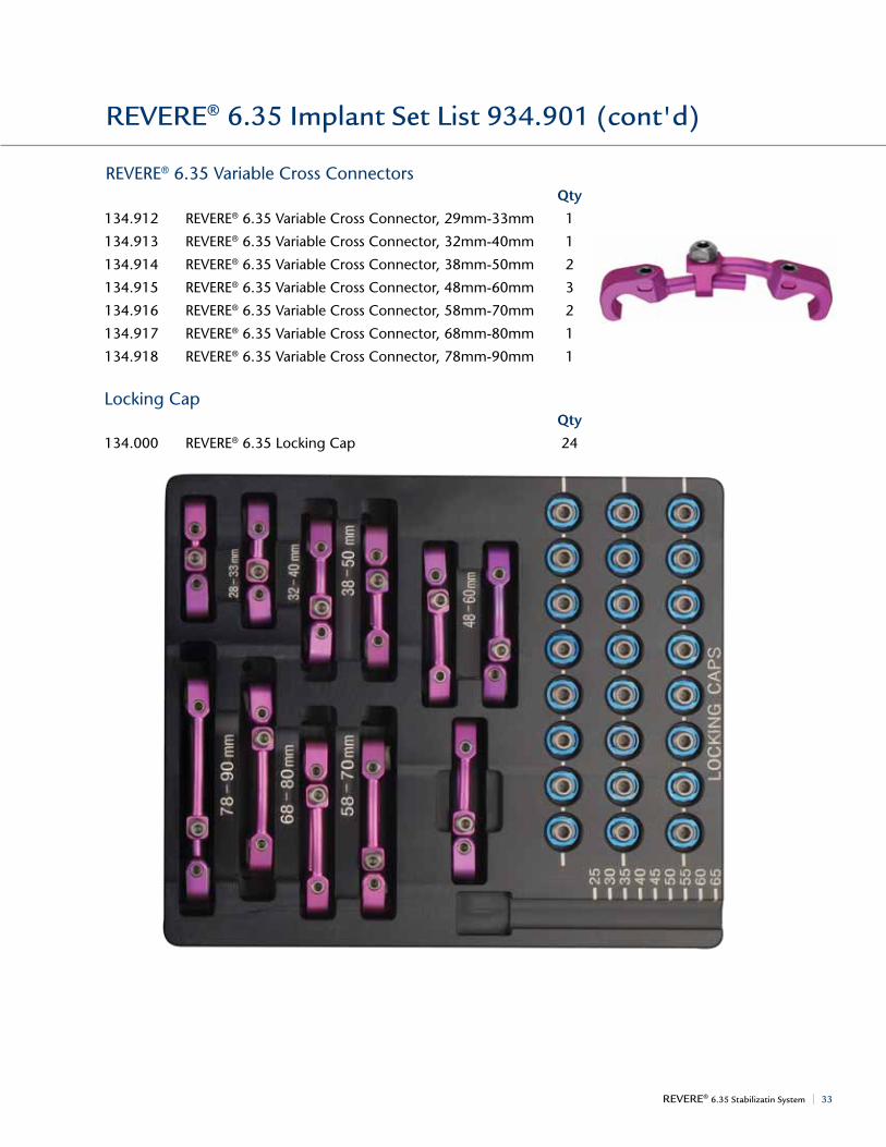
REVERE® 6.35 Stabilizatin System | 33
Qty
134.912 REVERE® 6.35 Variable cross connector, 29mm-33mm 1
134.913 REVERE®6.35VariableCrossConnector,32mm-40mm 1
134.914 REVERE® 6.35 Variable cross connector, 38mm-50mm 2
134.915 REVERE®6.35VariableCrossConnector,48mm-60mm 3
134.916 REVERE®6.35VariableCrossConnector,58mm-70mm 2
134.917 REVERE® 6.35 Variable cross connector, 68mm-80mm 1
134.918 REVERE®6.35VariableCrossConnector,78mm-90mm 1
locking cap Qty
134.000 REVERE®6.35LockingCap 24
Curved Rods – Ti Qty
155.635 6.35mmCurvedRod,35mm 4
155.640 6.35mmCurvedRod,40mm 4
155.645 6.35mmCurvedRod,45mm 4
155.650 6.35mmCurvedRod,50mm 4
155.655 6.35mmCurvedRod,55mm 4
155.660 6.35mm curved rod, 60mm 0
155.665 6.35mmCurvedRod,65mm 4
155.670 6.35mmCurvedRod,70mm 0
155.675 6.35mmCurvedRod,75mm 4
155.680 6.35mm curved rod, 80mm 0
155.685 6.35mmCurvedRod,85mm 4
155.690 6.35mm curved rod, 90mm 0
155.695 6.35mm curved rod, 95mm 0
155.610 6.35mm curved rod, 100mm 0
155.612 6.35mm curved rod, 125mm 0
155.615 6.35mm curved rod, 150mm 0
Curved Rods – CP Qty
134.635 6.35mmCurvedRodCP,35mm 0
134.640 6.35mmCurvedRodCP,40mm 0
134.645 6.35mmCurvedRodCP,45mm 0
134.650 6.35mmCurvedRodCP,50mm 0
134.655 6.35mmCurvedRodCP,55mm 0
134.660 6.35mmCurvedRodCP,60mm 0
134.665 6.35mmCurvedRodCP,65mm 0
134.670 6.35mmCurvedRodCP,70mm 0
134.675 6.35mmCurvedRodCP,75mm 0
134.680 6.35mmCurvedRodCP,80mm 0
134.685 6.35mmCurvedRodCP,85mm 0
134.690 6.35mmCurvedRodCP,90mm 0
134.695 6.35mmCurvedRodCP,95mm 0
134.610 6.35mmCurvedRodCP,100mm 0
134.612 6.35mmCurvedRodCP,125mm 0
134.615 6.35mmCurvedRodCP,150mm 0
REVERE® 6.35 implant Set list 934.901 (cont'd)
reVere® 6.35 Variable cross connectors
Life moves us34 |
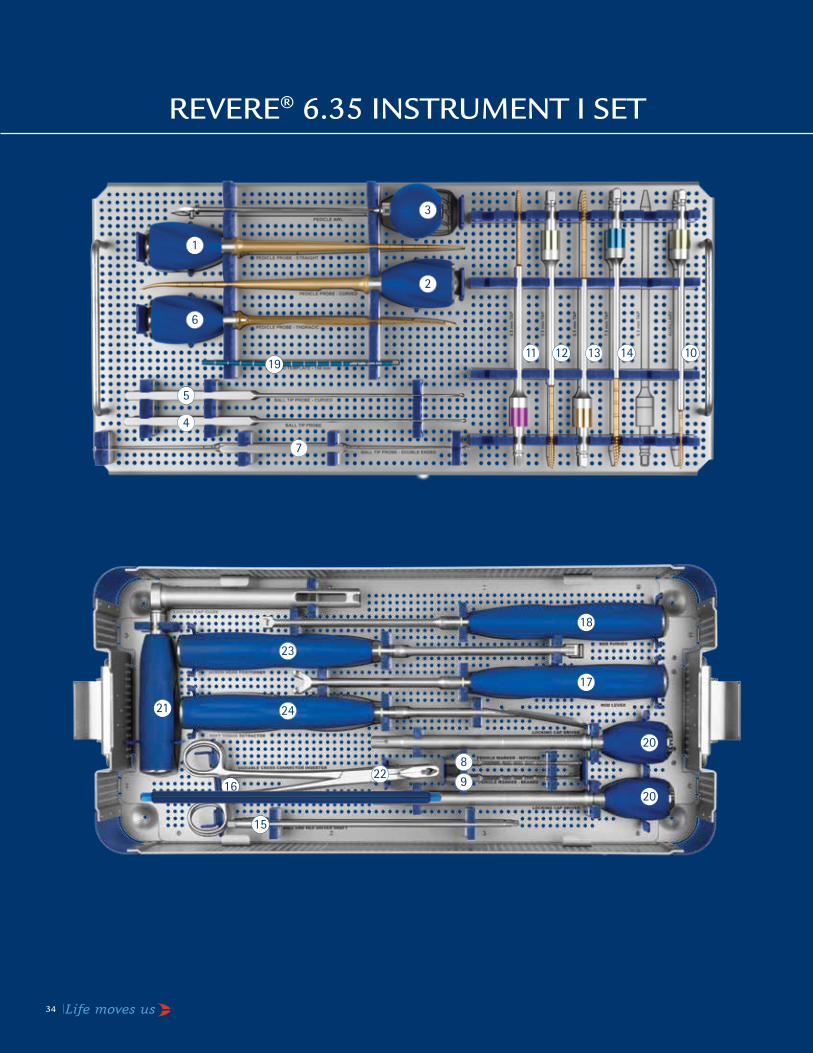
REVERE® 6.35 inStRUmEnt i SEt
1
2
3
4
5
17
6
7
8
9
1011 12 13 14
15
16
18
19
20
20
21
22
23
24

REVERE® 6.35 Stabilizatin System | 35
REVERE® 6.35 instrument i Set list 934.902
Pedicle Preparation Instruments Qty
602.101 PedicleProbe,Straight 1
602.102 PedicleProbe,Curved 1
602.104 PedicleAwl 1
602.105 BallTipProbe 1
602.106 BallTipProbe,Curved 1
602.109 PedicleProbe,Thoracic 1
624.110 BallTipProbe,DoubleEnded 1
602.107 PedicleMarker,Notched 4
602.108 PedicleMarker,Beaded 4
634.213 4.0mmTap 1
655.214 4.5mmTap 1
655.215 5.5mm Tap 1
655.216 6.5mm Tap 1
655.217 7.5mmTap 1
Screw Insertion Instruments Qty
630.411 BallEndHexDriverShaft 2
Rod Manipulation Instruments Qty
602.521 rod holder 1
634.511 6.35RodLever 1
634.513 6.35RodPusher 1
602.501 rod Template, 150mm 1
Screw Locking Instruments Qty
634.601 6.35LockingCapDriver 2
634.602 6.35LockingCapGuide 1
Variable Cross Connector Instrument Qty
634.606 VariableCrossConnectorInserter 1
Other Instruments
634.402 6.35ScrewHeadPositioner 1
634.514 6.35SoftTissueRetractor 1
934.002 REVERE® 6.35 instrument i graphic case
1
2
3
4
5
6
7
8
9
10
11
12
13
14
15
16
17
18
20
19
21
22
23
24

REVERE® 6.35 inStRUmEnt ii SEt
36 | Life moves us
1
2
3 4
567
8
8
910
11
12

REVERE® 6.35 Stabilizatin System | 37
Screw Insertion Instruments Qty
634.405 3.5mmHexScrewdriverShaft, 2 1/4"Connection
634.604 QuickDisconnect1/4",3.5mm 1 ratcheting Torque limiting T- handle
Rod Manipulation Instruments Qty
634.506 PowerBender 1
634.522 RodGripper,6.35Rod 1
624.503 ParallelCompressor 1
624.504 ParallelDistractor 1
634.505 6.35RodReducer,Ratcheted 1
634.800 6.35TowerReducer 2
624.801 T-Handle,Tower 1
Screw Locking Instruments Qty
634.603 6.35FinalTighteningCounterTorque1
Variable Cross Connector Instruments Qty
634.605 VariableCrossConnectorTemplate 1
602.430 TorqueLimiting2.5mmHexDriver 1
934.003 REVERE® 6.35 instrument ii graphic case
Additionally Available Instruments
655.218 8.5mm Tap
634.219 9.0mmTap
634.706 3.5mmHexDriver,1/4"Connect,Long
602.508 rod cutter
634.611 3.5mmTorqueLimitingDriver Ratcheting1/4"Connect,SS
630.401QuickRelease1/4",Ratchet,T-Handle
1
2
3
4
5
6
7
8
9
10
11
12
REVERE® 6.35 instrument ii Set list 934.903
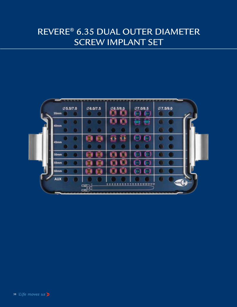
REVERE® 6.35 DUal oUtER DiamEtER SCREw imPlant SEt
38 | Life moves us

REVERE® 6.35 Stabilizatin System | 39
Length Ø5.5mm Qty30mm* 134.751 035mm 134.752 040mm 134.753 045mm 134.754 050mm 134.755 055mm 134.756 060mm 134.757 065mm 134.758 0
Length Ø6.0mm Qty30mm 134.761 035mm 134.762 240mm 134.763 245mm 134.764 250mm 134.765 255mm 134.766 260mm 134.767 265mm 134.768 0
Length Ø6.5mm Qty30mm 134.771 035mm 134.772 240mm 134.773 245mm 134.774 250mm 134.775 255mm 134.776 260mm 134.777 265mm 134.778 070mm 134.779 075mm 134.171 080mm 134.172 085mm 134.173 090mm 134.174 095mm 134.175 0100mm 134.176 0
REVERE® 6.35 Dual outer Diameter Screw implant Set list 934.912
reVere®6.35DualOuterDiameterScrews
Length Ø7.0mm Qty30mm 134.781 035mm 134.782 240mm 134.783 245mm 134.784 250mm 134.785 255mm 134.786 260mm 134.787 265mm 134.788 070mm 134.789 075mm 134.181 080mm 134.182 085mm 134.183 090mm 134.184 095mm 134.185 0100mm 134.186 0110mm 134.187 0120mm 134.188 0
Length Ø7.5mm Qty30mm 134.791 035mm 134.792 040mm 134.793 045mm 134.794 050mm 134.795 055mm 134.796 060mm 134.797 065mm 134.798 070mm 134.799 075mm 134.191 080mm 134.192 085mm 134.193 090mm 134.194 095mm 134.195 0100mm 134.196 0110mm 134.197 0120mm 134.198 0
*items highlighted in gray are additionally available.
934.012 REVERE®6.35DualOuterDiameterScrewGraphicCase

1
1
2
3
4
5
StainlESS StEEl REVERE® 6.35 imPlant SEt 934.909
40 | Life moves us
1
1
2
3
4
5

REVERE® 6.35 Stabilizatin System | 41
Length Ø5.5mm Qty25mm* 234.451 030mm 234.452 435mm 234.453 440mm 234.454 645mm 234.455 650mm 234.456 455mm 234.457 2
Length Ø6.5mm Qty25mm 234.461 030mm 234.462 435mm 234.463 440mm 234.464 1045mm 234.465 1050mm 234.466 855mm 234.467 460mm 234.468 265mm 234.469 2
Length Ø7.5mm Qty25mm 234.471 030mm 234.472 235mm 234.473 440mm 234.474 645mm 234.475 650mm 234.476 455mm 234.477 260mm 234.478 265mm 234.479 270mm 234.071 075mm 234.072 080mm 234.073 085mm 234.074 090mm 234.075 0
Length Ø8.5mm Qty25mm 234.481 030mm 234.482 035mm 234.483 040mm 234.484 045mm 234.485 050mm 234.486 055mm 234.487 060mm 234.488 065mm 234.489 070mm 234.081 075mm 234.082 080mm 234.083 085mm 234.084 090mm 234.085 095mm 234.086 0100mm 234.087 0110mm 234.088 0120mm 234.089 0
Length Ø9.0mm Qty25mm 234.491 030mm 234.492 035mm 234.493 040mm 234.494 045mm 234.495 050mm 234.496 055mm 234.497 060mm 234.498 065mm 234.499 070mm 234.091 075mm 234.092 080mm 234.093 085mm 234.094 090mm 234.095 095mm 234.096 0100mm 234.097 0110mm 234.098 0120mm 234.099 0
Stainless Steel REVERE® 6.35 implant Set list 934.909
SS reVere®6.35PolyaxialPedicleScrews
*items highlighted in gray are additionally available.
12345
instruments qty630.407 QuickRelease1/4",Ratchet,StraightHandle 2634.406 QuickDisconnect1/4"Non-Ratcheting,LargeSportHandle 1634.408 3.5mmHexDriverSelf-RetainingShaft,1/4"Connection 2634.703 3.5mmHexDriverRigidShaft 2634.704 6.35HoldingSleeveAssembly 2
934.009 SSREVERE® 6.35 implant graphic case
42 | Life moves us
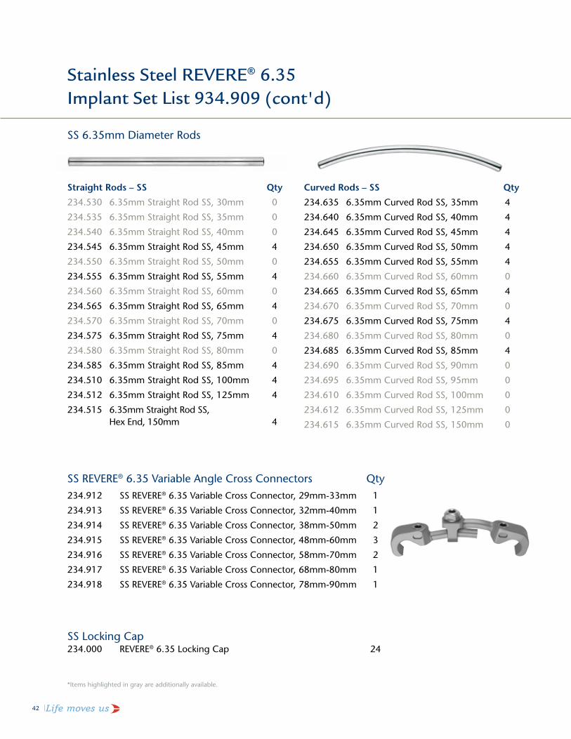
Stainless Steel REVERE® 6.35 implant Set list 934.909 (cont'd)
SS 6.35mm Diameter rods
Straight Rods – SS Qty
234.530 6.35mmStraightRodSS,30mm 0
234.535 6.35mmStraightRodSS,35mm 0
234.540 6.35mmStraightRodSS,40mm 0
234.545 6.35mmStraightRodSS,45mm 4
234.550 6.35mmStraightRodSS,50mm 0
234.555 6.35mmStraightRodSS,55mm 4
234.560 6.35mmStraightRodSS,60mm 0
234.565 6.35mmStraightRodSS,65mm 4
234.570 6.35mmStraightRodSS,70mm 0
234.575 6.35mmStraightRodSS,75mm 4
234.580 6.35mmStraightRodSS,80mm 0
234.585 6.35mmStraightRodSS,85mm 4
234.510 6.35mmStraightRodSS,100mm 4
234.512 6.35mmStraightRodSS,125mm 4
234.515 6.35mmStraightRodSS, HexEnd,150mm 4
*items highlighted in gray are additionally available.
Curved Rods – SS Qty
234.635 6.35mmCurvedRodSS,35mm 4
234.640 6.35mmCurvedRodSS,40mm 4
234.645 6.35mmCurvedRodSS,45mm 4
234.650 6.35mmCurvedRodSS,50mm 4
234.655 6.35mmCurvedRodSS,55mm 4
234.660 6.35mmCurvedRodSS,60mm 0
234.665 6.35mmCurvedRodSS,65mm 4
234.670 6.35mmCurvedRodSS,70mm 0
234.675 6.35mmCurvedRodSS,75mm 4
234.680 6.35mmCurvedRodSS,80mm 0
234.685 6.35mmCurvedRodSS,85mm 4
234.690 6.35mmCurvedRodSS,90mm 0
234.695 6.35mmCurvedRodSS,95mm 0
234.610 6.35mmCurvedRodSS,100mm 0
234.612 6.35mmCurvedRodSS,125mm 0
234.615 6.35mmCurvedRodSS,150mm 0
SS reVere® 6.35 Variable angle cross connectors qty234.912 SSREVERE® 6.35 Variable cross connector, 29mm-33mm 1
234.913 SSREVERE®6.35VariableCrossConnector,32mm-40mm 1
234.914 SSREVERE® 6.35 Variable cross connector, 38mm-50mm 2
234.915 SSREVERE®6.35VariableCrossConnector,48mm-60mm 3
234.916 SSREVERE®6.35VariableCrossConnector,58mm-70mm 2
234.917 SSREVERE® 6.35 Variable cross connector, 68mm-80mm 1
234.918 SSREVERE®6.35VariableCrossConnector,78mm-90mm 1
SS locking cap234.000 REVERE®6.35LockingCap 24

REVERE® 6.35 Stabilizatin System | 43
DESCRIPTIONThe REVERE® Stabilization System consists of rods, hooks, monoaxial screws, uniplanar screws, polyaxial screws, reduction screws, locking caps, t-connectors, offset housing clamps, head offset connectors, trans iliac connectors, staples, and associated manual surgical instruments. Screws and rods are available in a variety of sizes to accommodate individual patient anatomy. REVERE® implants mate with 5.5mm diameter rods; REVERE® 6.35 implants mate with 6.35mm diameter rods. Implant components can be rigidly locked into a variety of configurations for the individual patient and surgical condition. Polyaxial screws, hooks, and t-connectors are intended for posterior use only. Staples are intended for anterior use only. Rods and monoaxial screws may be used anteriorly or posteriorly. Locking caps are used to connect screws or hooks to the rod and trans iliac connectors.
The most common use of this screw, hook, and rod system in the posterior thoracolumbar and sacral spine is two rods, each positioned and attached lateral to the spinous process via pedicle screws and/or lamina, pedicle or transverse process hooks.
The most common use of this screw, hook, and rod system in the anterior thoracolumbar spine is one rod, positioned and attached to the vertebral bodies via monoaxial screws through an appropriate size staple.
Screws and hooks attach to the rods using a locking cap with an inner set screw. The size and number of screws are dependent on the length and location of the rod. Screws are inserted into a pedicle of the thoracolumbar and/or sacral spine. The type and number of hooks are also dependent on the location in the spine needing correction and/or stabilization. Hooks are attached to the laminae, pedicles, or transverse process of the posterior spine.
T-connectors are modular components designed to connect the two rods of a construct and act as a structural cross member. The rod-clamping set screws secure the t-connectors to the rods. Additional set screws secure the adjustable cross members at the desired length. T-connectors from the PROTEX® system may be used with 6.5mm, 6.0mm or 5.5mm rod systems. REVERE® t-connectors may only be used with 5.5mm rods; REVERE® 6.35 t-connectors may only be used with 6.35mm rods. Additional connectors may be used to connect two rods, and are also secured using set screws.
REVERE® rods are composed of titanium alloy, commercially pure titanium, or stainless steel, as specified in ASTM F136, F1472, F1295, F67, and F138. All other REVERE® implants are composed of titanium alloy or stainless steel, as specified in ASTM F136, F1472, F1295, and F138. Due to the risk of galvanic corrosion following implantation, stainless steel implants should not be connected to titanium or titanium alloy implants.
INDICATIONS The REVERE® Stabilization System, when used as a posterior pedicle screw system, is intended to provide immobilization and stabilization of spinal segments in skeletally mature patients as an adjunct to fusion in the treatment of the following acute and chronic instabilities or deformities of the thoracic, lumbar and sacral spine: degenerative disc disease (defined as discogenic back pain with degeneration of the disc confirmed by history and radiographic studies), degenerative spondylolisthesis with objective evidence of neurologic impairment, fracture, dislocation, scoliosis, kyphosis, spinal tumor, pseudoarthrosis and failed previous fusion.
In addition, the REVERE® Stabilization System is intended for treatment of severe spondylolisthesis (Grades 3 and 4) of the L5-S1 vertebra in skeletally mature patients receiving fusion by autogenous bone graft, having implants attached to the lumbosacral spine and/or ilium with removal of the implants after attainment of a solid fusion. Levels of pedicle screw fixation for these patients are L3-sacrum/ilium.
When used as a posterior non-pedicle screw fixation system, the REVERE® Stabilization System is intended for the treatment of degenerative disc disease (defined as discogenic back pain with degeneration of the disc confirmed by history and radiographic studies), spinal stenosis, spondylolisthesis, spinal deformities (i.e. scoliosis, kyphosis, and/or lordosis, Scheuermann’s disease), fracture, pseudoarthrosis, tumor resection, and/or failed previous fusion. Overall levels of fixation are T1-sacrum/ilium.
When used as an anterolateral thoracolumbar system, the REVERE® Stabilization System is intended for anterolateral screw (with or without staple) fixation for the following indications: degenerative disc disease (defined as discogenic back pain with degeneration of the disc confirmed by history and radiographic studies), spinal stenosis, spondylolisthesis, spinal deformities (i.e. scoliosis, kyphosis, and/or lordosis), fracture or dislocation of the thoracolumbar spine, pseudoarthrosis, tumor resection, and/or failed previous fusion. Levels of screw fixation are T8-L5.
WARNINGSThe safety and effectiveness of pedicle screw spinal systems have been established only for spinal conditions with significant mechanical instability or deformity requiring fusion with instrumentation. These conditions are significant mechanical instability or deformity of the thoracic, lumbar, and sacral spine secondary to degenerative disc disease, degenerative spondylolisthesis with objective evidence of neurologic impairment, fracture, dislocation, scoliosis, kyphosis, spinal tumor and failed previous fusion (pseudoarthrosis). The safety and effectiveness of these devices for any other conditions are unknown.
One of the potential risks identified with this system is death. Other potential risks which may require additional surgery, include:
• devicecomponentfracture,• lossoffixation, • non-union, • fractureofthevertebrae, • neurologicalinjury,and • vascularorvisceralinjury.
The components of this system are manufactured from titanium alloy. Mixing of implant components with different materials is not recommended, for metallurgical, mechanical and functional reasons.
PRECAUTIONSThe implantation of screw, hook and rod systems should be performed only by experienced spinal surgeons with specific training in the use of this system because this is a technically demanding procedure presenting a risk of serious injury to the patient. Preoperative planning and patient anatomy should be considered when selecting screw diameter and length, and hook size.
The REVERE® Stabilization System includes 5.5mm REVERE® implants intended for use with a 5.5mm rod and REVERE® 6.35 implants intended for use with a 6.35mm rod.
ATTENTIONSee Warnings, Precautions and Potential Adverse Events sections of the insert entitled "Suggestions Concerning Orthopaedic Metallic Internal Fixation Devices” for a complete list of potential risks.
CONTRAINDICATIONSCertain degenerative diseases or underlying physiological conditions such as diabetes or rheumatoid arthritis may alter the healing process, thereby increasing the risk of implant breakage.
Mental or physical impairment which compromises a patient’s ability to comply with necessary limitations or precautions may place that patient at a particular risk during postoperative rehabilitation.
Factors such as the patient’s weight, activity level, and adherence to weight bearing or load bearing instructions have an effect on the stresses to which the implant is subjected.
CLEANINGCleaning instruments by hand, when properly carried out, causes less damage than mechanical cleaning. When cleaning instruments by hand, the following should be observed:
1. Clear any corners or recesses of all debris. (Note: extra care should be taken to clean out any cannulated areas by using an appropriate cleaning stylet and rinsing immediately.)
2. Remove all traces of blood and other such residues immediately. Do not allow these to dry.
3. The instruments should be submerged (if applicable) and cleaned with a commercially available manual cleaner (i.e. Instraclean from Calgon or Medline High Suds Detergent) prepared according to the manufacturer’s recommendation.
4. A soft nylon bristled brush is then used to manually clean the devices while immersed in the cleaning solution. Never use steel brushes or abrasive pads, as these rupture the passive layer of the instrument surface which can lead to corrosion.
5. The instruments should be thoroughly rinsed after cleaning. Distilled water should be used.
6. Dry instruments immediately after cleaning.
CONTACT INFORMATIONGlobus Medical may be contacted at 1-866-GLOBUS1 (456-2871). A surgical technique manual may be obtained by contacting Globus Medical.
STERILIZATIONREVERE® implants and instruments may be provided sterile or non-sterile. Sterile implants and instruments are sterilized by gamma radiation to ensure a sterility assurance level of 10-6 SAL. The expiration date is provided in the package label. Sterile implants and instruments that are provided STERILE should be considered sterile unless the packaging has been opened or damaged.
Non-sterile REVERE® implants and instruments have been validated to assure a Sterility Assurance Level (SAL) of 10-6. The use of an FDA cleared wrap is recommended, per the Association for the Advancement of Medical Instrumentation (AAMI) ST79, Comprehensive Guide to Steam Sterilization and Sterility Assurance in Health Care Facilities.
Implants:These devices are supplied NONSTERILE. Sterilization is recommended as follows:
Method Cycle Type Temperature Exposure Time Drying TimeSteam Gravity Displacement
(Wrapped)132° - 135°C(270° - 275° F)
28 Minutes 0 Minutes
Steam Pre-vacuum (Wrapped) Preconditioning Pulses: 3
132° - 135°C(270° - 275° F)
4 Minutes 0 Minutes
Instruments:These instruments are supplied NONSTERILE. Sterilization is recommended as follows:
Method Cycle Type Temperature Exposure Time Drying TimeSteam Gravity Displacement
(Wrapped)132° - 135°C(270° - 275° F)
25 Minutes 45 Minutes
Steam Pre-vacuum (Wrapped) Preconditioning Pulses: 3
132° - 135°C(270° - 275° F)
15 Minutes 30 Minutes
These parameters are validated to sterilize only this device. If other products are added to the sterilizer, the recommended parameters are not valid and new cycle parameters must be established by the user. The autoclave must be properly installed, maintained, and calibrated. Ongoing testing must be performed to confirm inactivation of all forms of viable microorganisms.
CAUTION: Federal (U.S.A) Law Restricts this Device to Sale by or on the order of a Physician.
IMPORTAnT InFORMATIOn On THe ReVeRe® 6.35 STAbILIzATIOn SySTeM

44 | Life moves us
Notes

REVERE® 6.35 Stabilizatin System | 45
Notes

Globus MedicalValley Forge Business Center2560 General Armistead AvenueAudubon, PA 19403www.globusmedical.com
Customer Service:Phone 1-866-GLOBUS1 (or 1-866-456-2871) Fax 1-866-GLOBUS3 (or 1-866-456-2873)
GMTGD54 03.10
P: RMS – UK Limited 28 Trinity Road, Nailsea, Somerset, BS484NU England
©2010 Globus Medical. All rights reserved. Patents pending. Life moves us is a trademark of Globus Medical. REVERE is a registered trademark of Globus Medical. Please refer to package insert for description, indications, contraindications, warnings, precautions and other important information.