review exam 2. light behaves like all waves the frequency of an electromagnetic wave is related to...
TRANSCRIPT
Review Exam 2

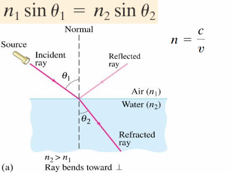
Light Behaves Like All Waves
The frequency of an electromagnetic wave is related to its wavelength:
Wavelengths of visible light: 400 nm to 750 nm
Shorter wavelengths are ultraviolet; longer are infrared
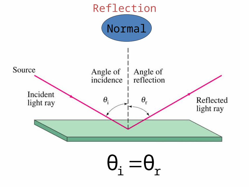
Reflection
ri θθ
Normal
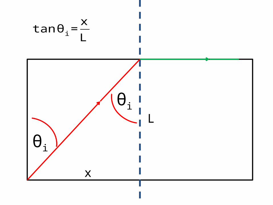
θi
θi
tan θi =xL
x
L
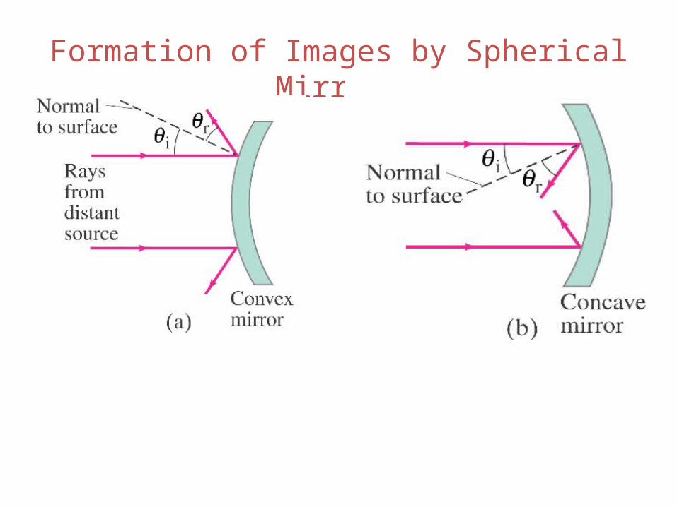
Formation of Images by Spherical Mirrors
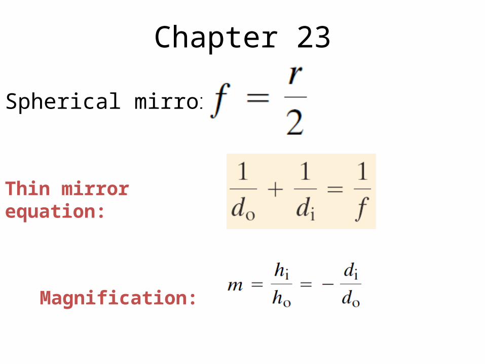
Chapter 23
Thin mirror equation:
Magnification:
Spherical mirror
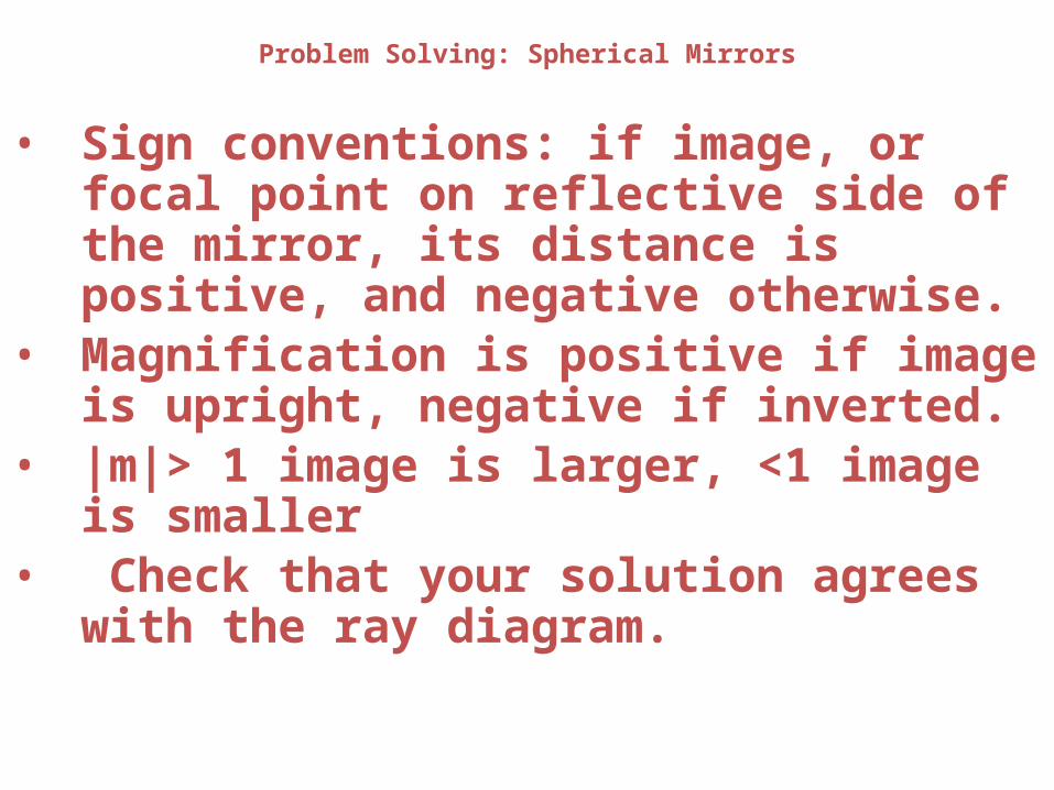
Problem Solving: Spherical Mirrors
• Sign conventions: if image, or focal point on reflective side of the mirror, its distance is positive, and negative otherwise.
• Magnification is positive if image is upright, negative if inverted.
• |m|> 1 image is larger, <1 image is smaller• Check that your solution agrees with the ray
diagram.
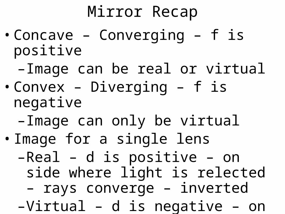
Mirror Recap• Concave – Converging – f is positive–Image can be real or virtual
• Convex – Diverging – f is negative–Image can only be virtual
• Image for a single lens –Real – d is positive – on side where light is
relected – rays converge – inverted–Virtual – d is negative – on opposite side as
object – rays diverge - upright
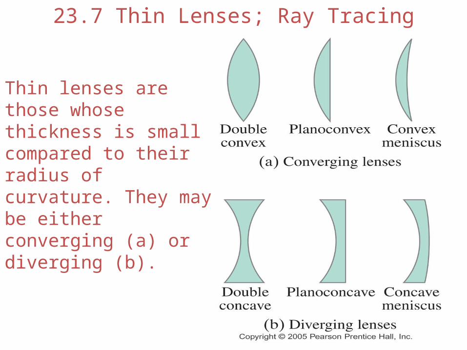
23.7 Thin Lenses; Ray Tracing
Thin lenses are those whose thickness is small compared to their radius of curvature. They may be either converging (a) or diverging (b).
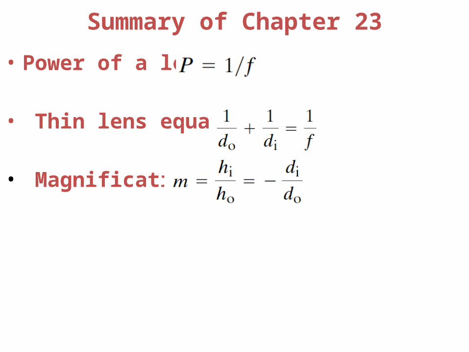
Summary of Chapter 23
• Power of a lens:
• Thin lens equation:
• Magnification:
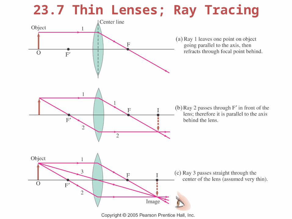
23.7 Thin Lenses; Ray Tracing
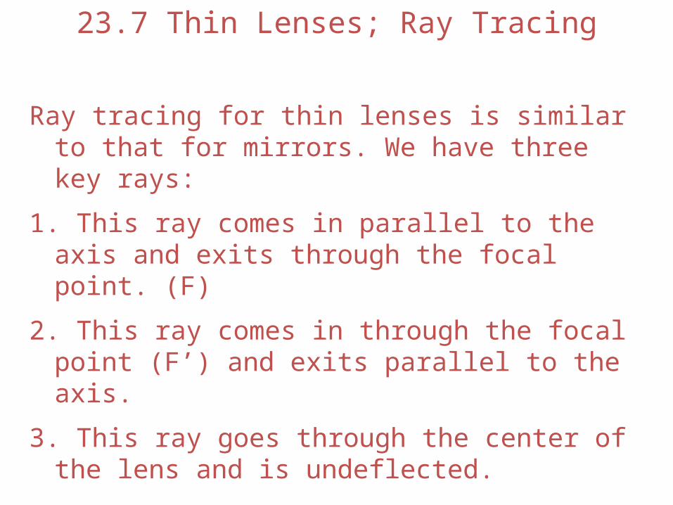
Ray tracing for thin lenses is similar to that for mirrors. We have three key rays:
1. This ray comes in parallel to the axis and exits through the focal point. (F)
2. This ray comes in through the focal point (F’) and exits parallel to the axis.
3. This ray goes through the center of the lens and is undeflected.
23.7 Thin Lenses; Ray Tracing
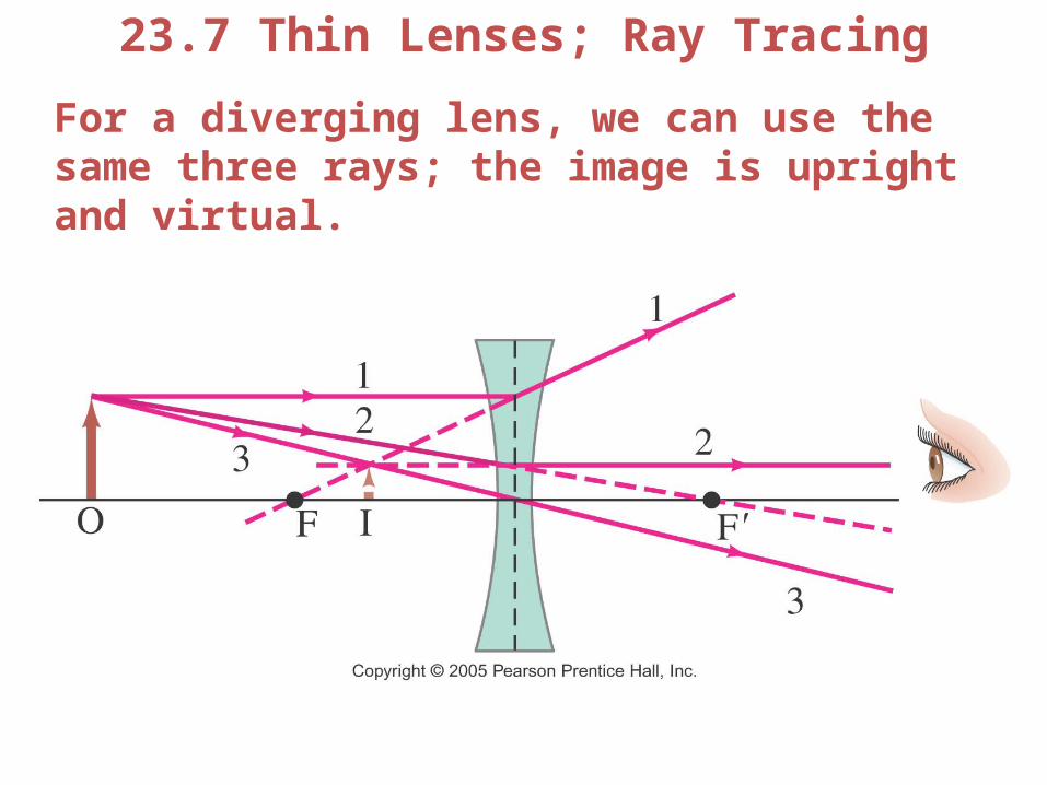
23.7 Thin Lenses; Ray Tracing
For a diverging lens, we can use the same three rays; the image is upright and virtual.

Lens Recap• Convex – Converging – f is positive–Image can be real or virtual
• Concave – Diverging – f is negative–Image can only be virtual
• Image for a single lens –Real – d is positive – on side where light is
transmitted – rays converge – inverted–Virtual – d is negative – on same side as
object – rays diverge - upright
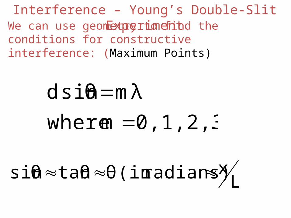
Interference – Young’s Double-Slit ExperimentWe can use geometry to find the conditions for constructive interference: (Maximum Points)
..0,1,2,3,.. m where
mλsinθ d
Lxradians)(in θtanθsinθ
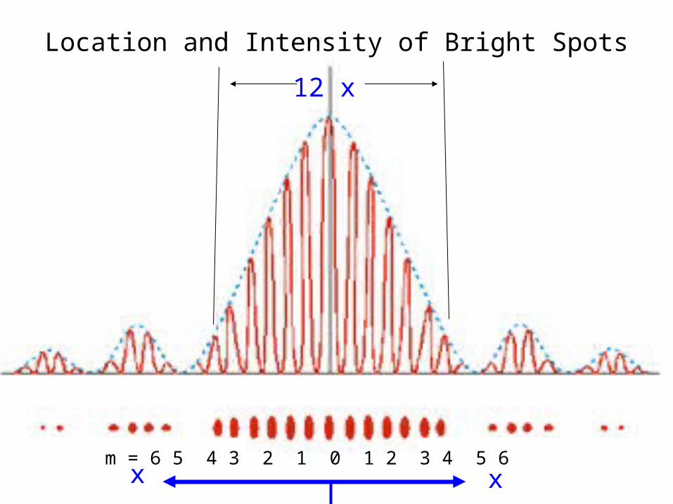
Location and Intensity of Bright Spots
m = 6 5 4 3 2 1 0 1 2 3 4 5 6 xx
12 x
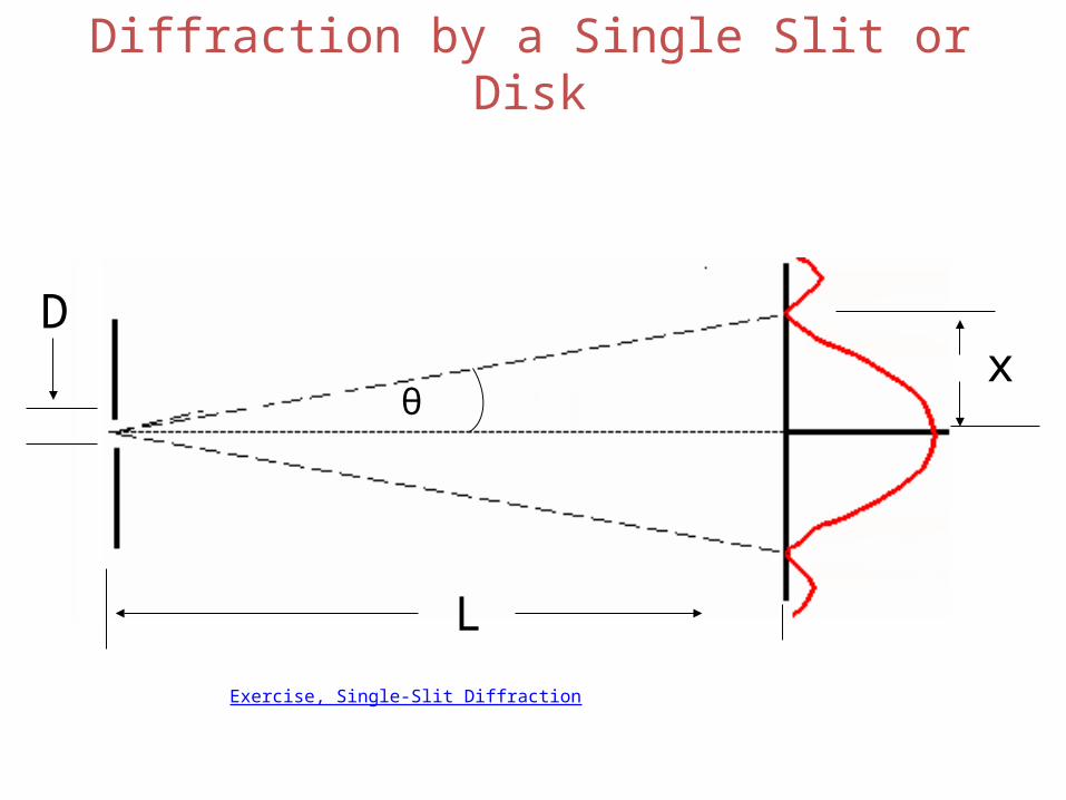
Diffraction by a Single Slit or Disk
Dx
L
θ
Exercise, Single-Slit Diffraction
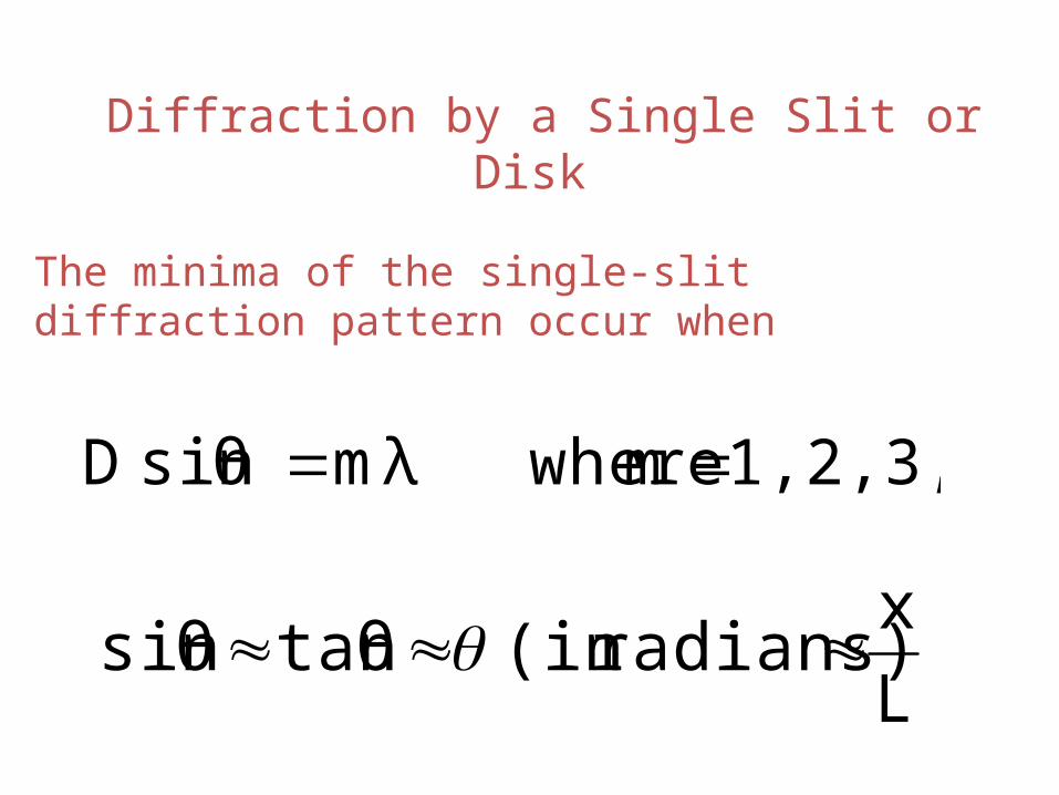
Diffraction by a Single Slit or Disk
The minima of the single-slit diffraction pattern occur when
1,2,3,.... m wheremλsinθ D
L
xradians)(in tanθsinθ
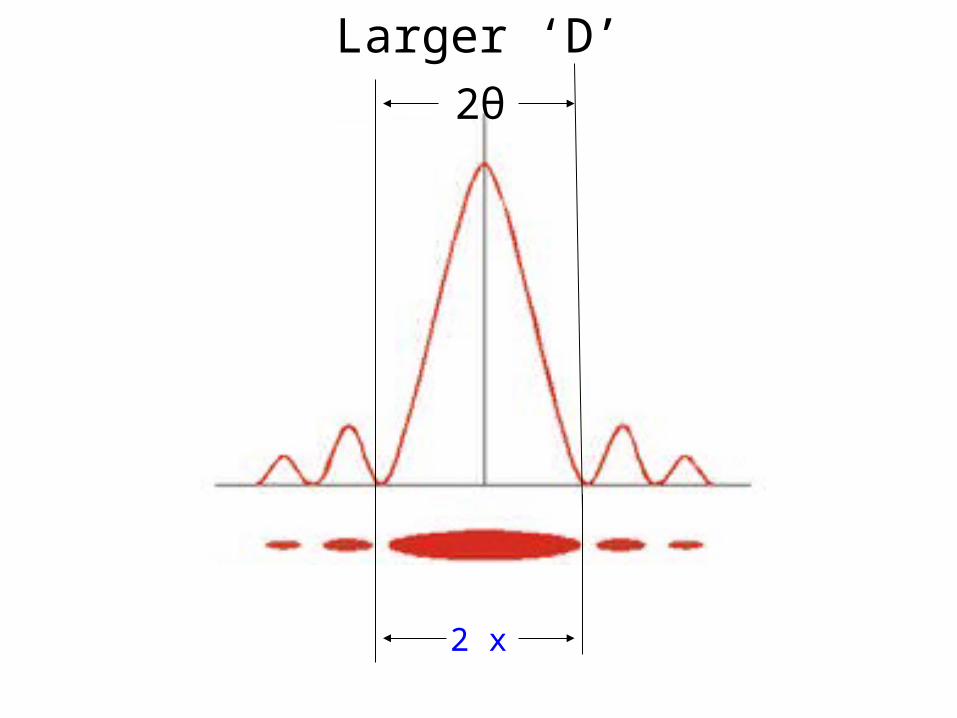
Larger ‘D’2θ
2 x
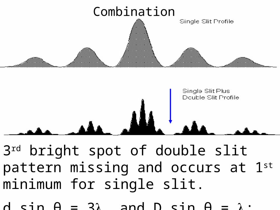
Combination
3rd bright spot of double slit pattern missing and occurs at 1st minimum for single slit.
d sin θ = 3 and D sin θ = ; d/D = 3
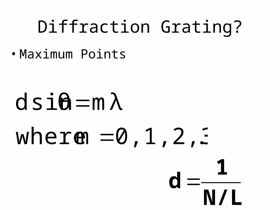
Diffraction Grating?
N/L
1 d
• Maximum Points
..0,1,2,3,.. m where
mλsinθ d

24.10 Polarization
This means that if initially unpolarized light passes through crossed polarizers, no light will get through the second one.
I0I0/2