rf safety for interventional mri procedures ergin atalar, ph.d. bilkent university, ankara, turkey...
TRANSCRIPT
RF Safety for Interventional MRI Procedures
Ergin Atalar, Ph.D.Bilkent University, Ankara, Turkey
Johns Hopkins University, Baltimore MD USA
Ergin Atalar, Ph.D.
Introduction
• Interference with iMRI devices– Guidewires/Catheters– Needles– Surgical tools
• Excessive heating and burns
Ergin Atalar, Ph.D.
RF Heating of Guidewires
• Problem is extensively studied– Heating is real– Sources of problem are well-known
• Conflicting measurement methods are proposed
• Guidelines are not well-established
Ergin Atalar, Ph.D.
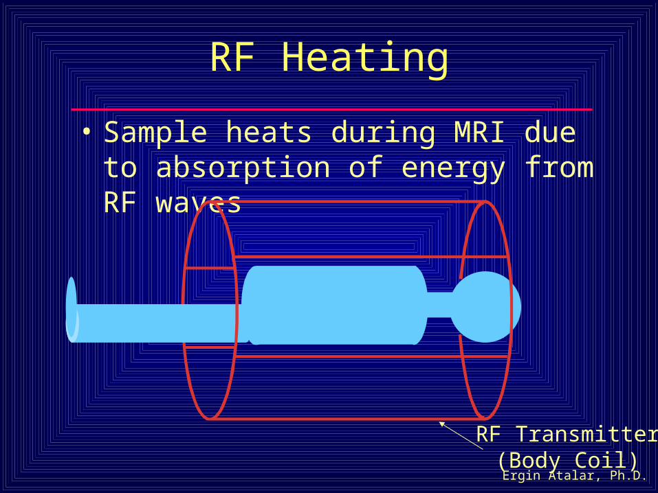
RF Heating
• Sample heats during MRI due to absorption of energy from RF waves
RF Transmitter(Body Coil)
Ergin Atalar, Ph.D.
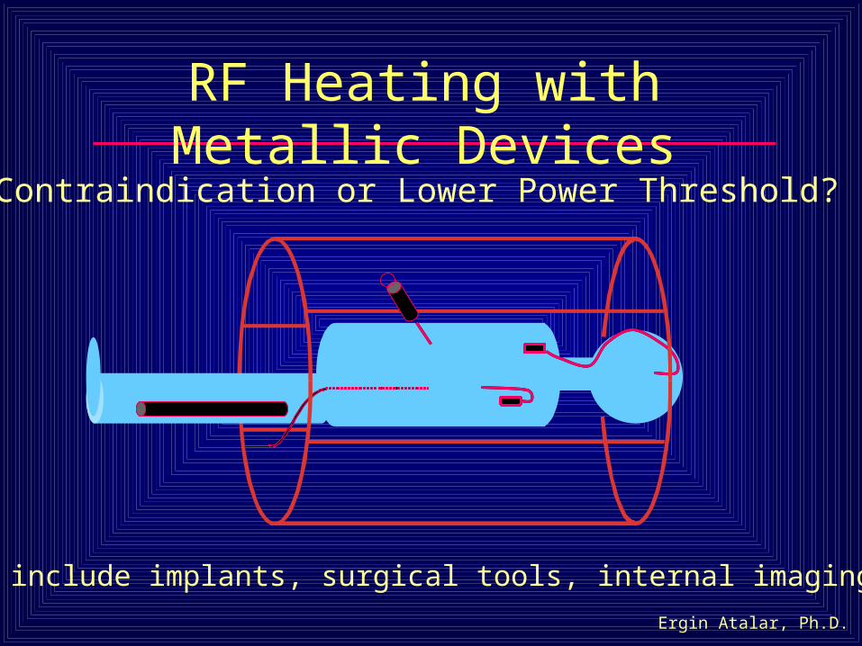
RF Heating with Metallic Devices
Devices include implants, surgical tools, internal imaging coils
Contraindication or Lower Power Threshold?
Ergin Atalar, Ph.D.
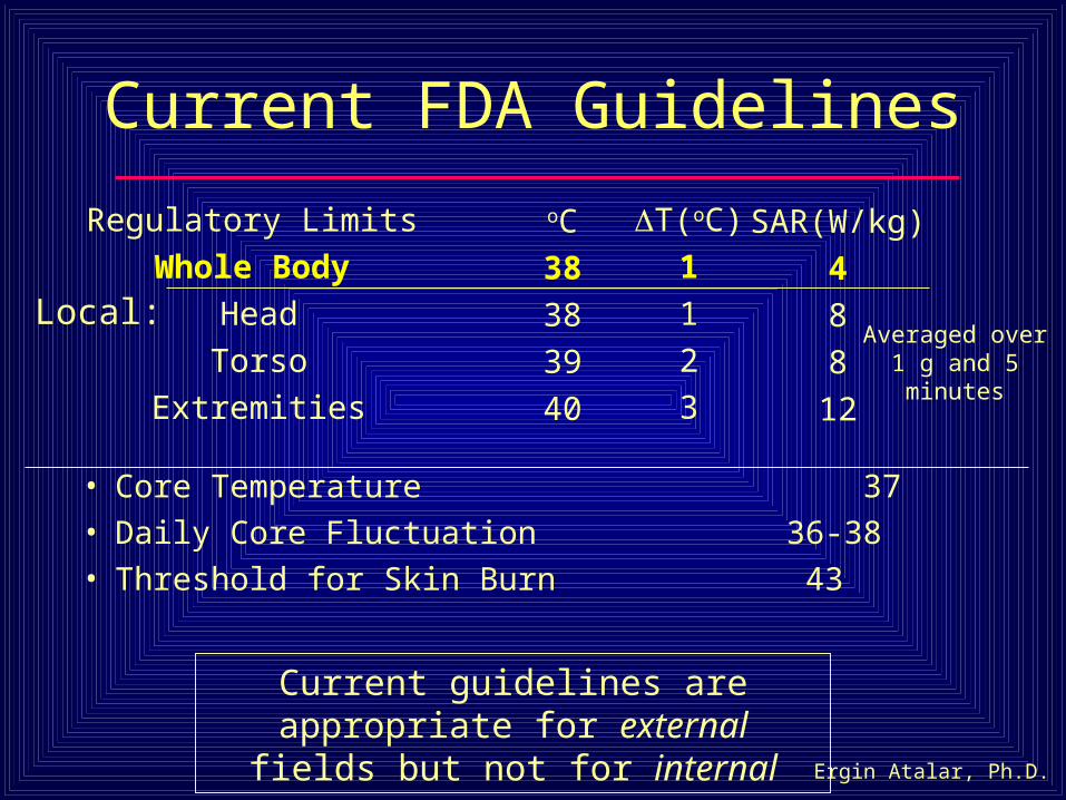
Current FDA Guidelines
• Core Temperature 37
• Daily Core Fluctuation 36-38
• Threshold for Skin Burn 43
Current guidelines are appropriate for external fields but not for internal
SAR(W/kg)
4
8
8
12
Regulatory Limits
Whole Body
Head
Torso
Extremities
oC
38
38
39
40
Averaged over 1 g and 5 minutes
T(oC)
1
1
2
3
Local:
Ergin Atalar, Ph.D.
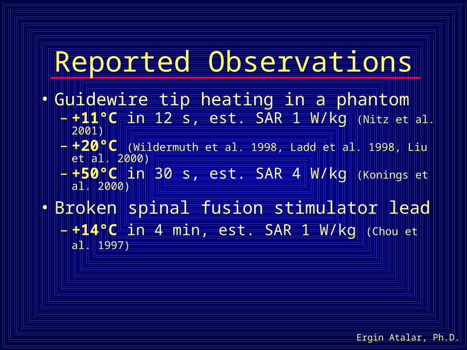
Reported Observations• Guidewire tip heating in a phantom
– +11°C in 12 s, est. SAR 1 W/kg (Nitz et al. 2001)
– +20°C (Wildermuth et al. 1998, Ladd et al. 1998, Liu et al. 2000)
– +50°C in 30 s, est. SAR 4 W/kg (Konings et al. 2000)
• Broken spinal fusion stimulator lead– +14°C in 4 min, est. SAR 1 W/kg (Chou et al. 1997)
Ergin Atalar, Ph.D.
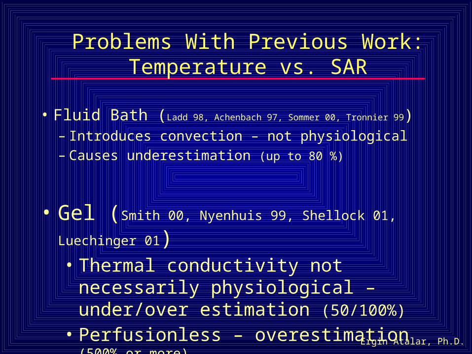
Problems With Previous Work: Temperature vs. SAR
• Fluid Bath (Ladd 98, Achenbach 97, Sommer 00, Tronnier 99)– Introduces convection – not physiological– Causes underestimation (up to 80 %)
• Gel (Smith 00, Nyenhuis 99, Shellock 01, Luechinger 01)• Thermal conductivity not necessarily
physiological – under/over estimation (50/100%)
• Perfusionless – overestimation (500% or more)
Ergin Atalar, Ph.D.
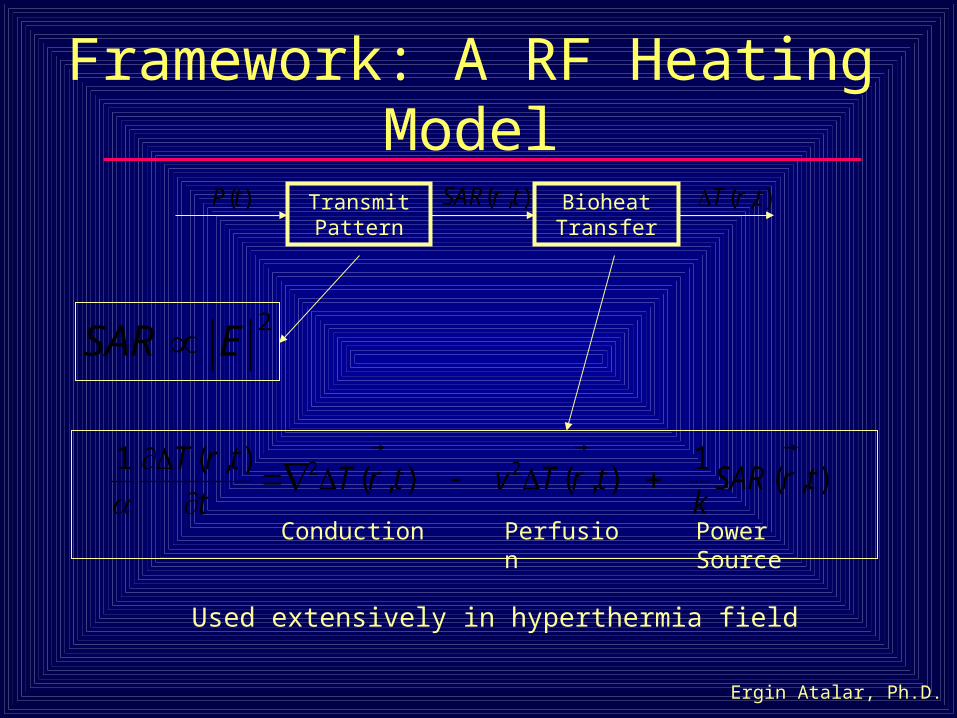
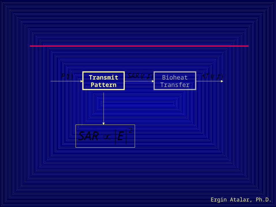
Framework: A RF Heating Model
2ESAR
Conduction Power SourcePerfusion
Used extensively in hyperthermia field
),(1
),(),(),(1 22 trSAR
ktrTvtrT
t
trT
Transmit Pattern
Bioheat Transfer
( , )SAR r t
( , )T r t
( )P t
Ergin Atalar, Ph.D.
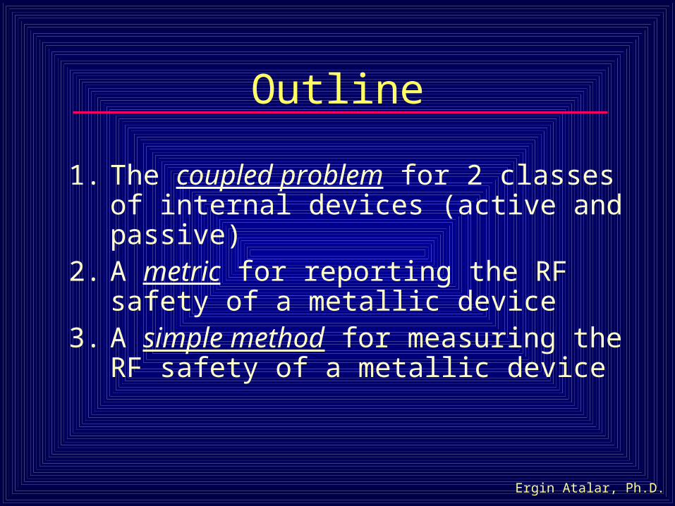
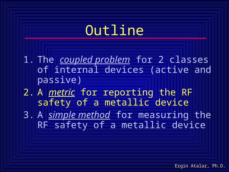
Outline
1. The coupled problem for 2 classes of internal devices (active and passive)
2. A metric for reporting the RF safety of a metallic device
3. A simple method for measuring the RF safety of a metallic device
Ergin Atalar, Ph.D.
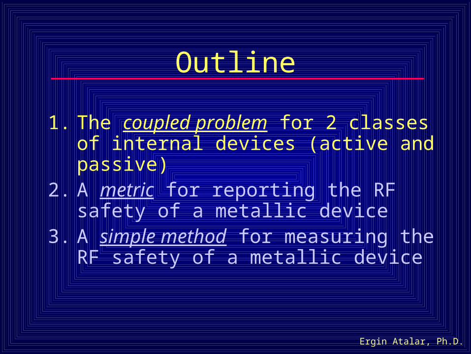
Outline
1. The coupled problem for 2 classes of internal devices (active and passive)
2. A metric for reporting the RF safety of a metallic device
3. A simple method for measuring the RF safety of a metallic device
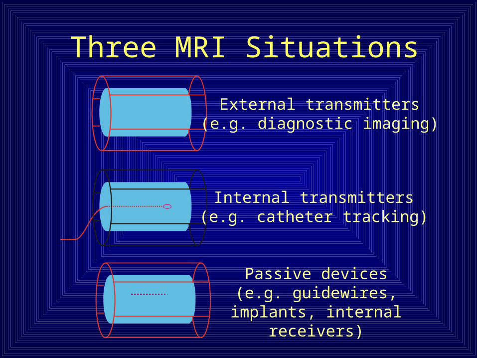
Three MRI Situations
Internal transmitters(e.g. catheter tracking)
Passive devices(e.g. guidewires, implants,
internal receivers)
External transmitters(e.g. diagnostic imaging)
Ergin Atalar, Ph.D.
Transmit Pattern
Bioheat Transfer
2ESAR
( , )SAR r t
( , )T r t
( )P t
Ergin Atalar, Ph.D.
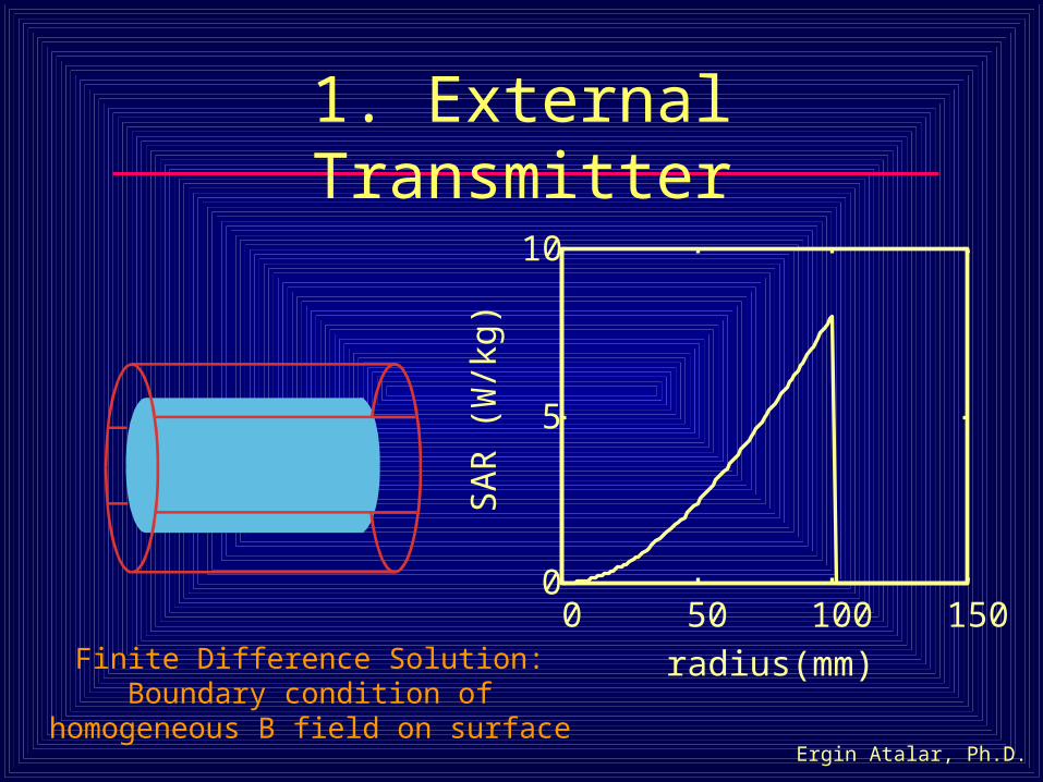
1. External Transmitter
0 50 100 1500
5
10
radius(mm)
SA
R (
W/k
g)
Finite Difference Solution: Boundary condition of homogeneous B field on surface
Ergin Atalar, Ph.D.
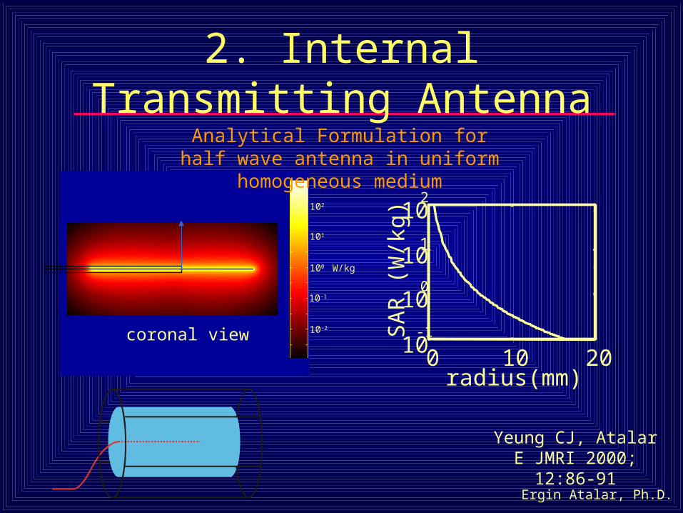
2. Internal Transmitting Antenna
Yeung CJ, Atalar E JMRI 2000; 12:86-91
W/kg100
102
10-1
101
10-2
coronal view
Analytical Formulation for half wave antenna in uniform homogeneous medium
0 10 2010
-1
100
101
102
radius(mm)S
AR
(W
/kg)
Ergin Atalar, Ph.D.
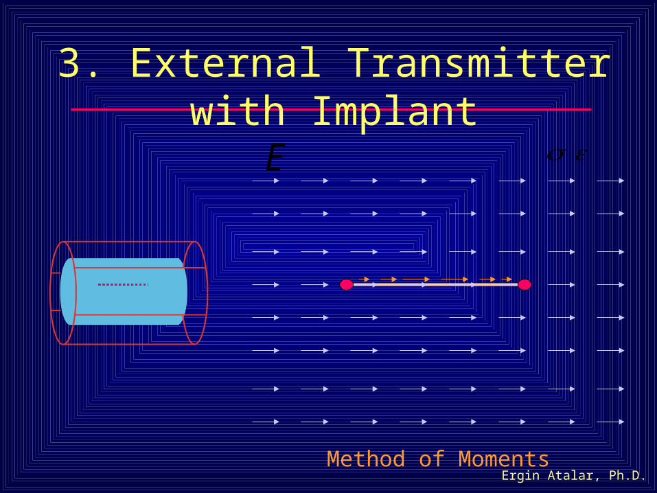
3. External Transmitter with Implant
E
Method of Moments
Ergin Atalar, Ph.D.
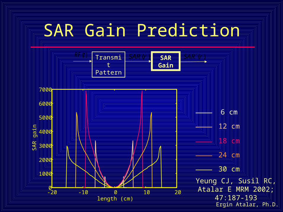
SAR Gain Prediction
-20 -10 0 10 200
1000
2000
3000
4000
5000
6000
7000
length (cm)
SA
R g
ain
Transmit Pattern
( )RF t )(rSAR
)(rRSASAR
Gain
6 cm
12 cm
18 cm
24 cm
30 cm
Yeung CJ, Susil RC, Atalar E MRM 2002; 47:187-193
Ergin Atalar, Ph.D.
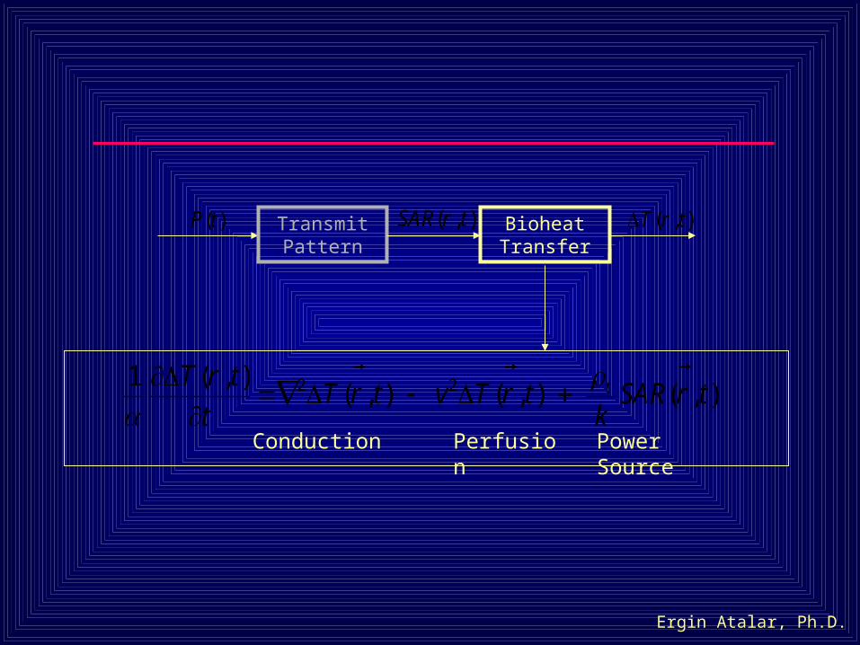
Transmit Pattern
Bioheat Transfer
Conduction Power SourcePerfusion
2 21 ( , )( , ) ( , ) ( , )tT r t
T r t v T r t SAR r tt k
( , )SAR r t
( , )T r t
( )P t
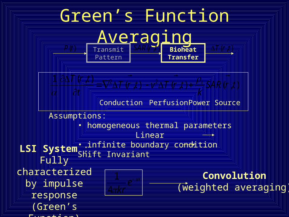
Green’s Function Averaging
2 21 ( , )( , ) ( , ) ( , )tT r t
T r t v T r t SAR r tt k
Convolution(weighted averaging)
LSI System :Fully characterized by
impulse response (Green’s Function)
vrekr
4
1
Conduction Perfusion Power Source
Assumptions:• homogeneous thermal parameters Linear• infinite boundary condition Shift Invariant
Transmit Pattern
Bioheat Transfer
( , )SAR r t
( , )T r t
( )P t
Ergin Atalar, Ph.D.
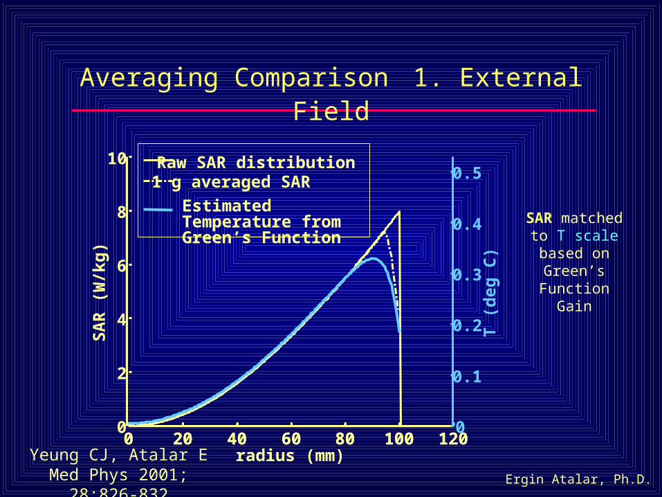
Averaging Comparison 1. External Field
0 20 40 60 80 100 1200
2
4
6
8
10
SA
R (
W/k
g)
radius (mm)
Raw SAR distribution 1 g averaged SAR
Estimated Temperature from Green’s Function
0 20 40 60 80 100 1200
0.1
0.2
0.3
0.4
0.5
T (
deg
C)
Yeung CJ, Atalar EMed Phys 2001; 28:826-832
SAR matched to T scale based on Green’s Function
Gain
Ergin Atalar, Ph.D.
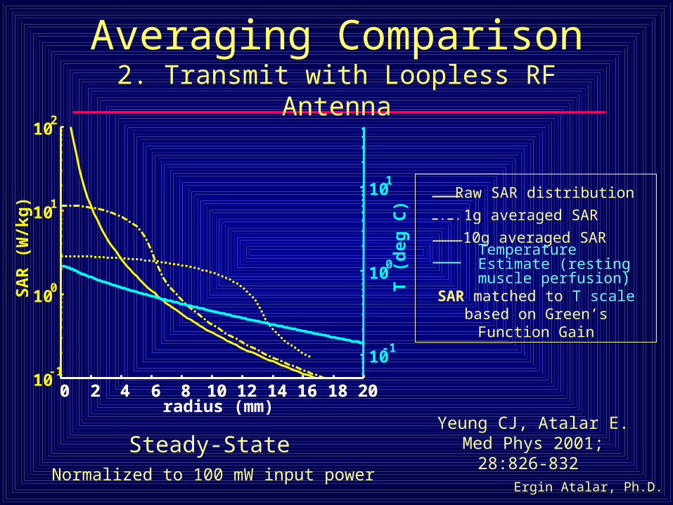
Averaging Comparison2. Transmit with Loopless RF Antenna
Steady-State
Raw SAR distribution
1g averaged SAR
10g averaged SARTemperature Estimate (resting muscle perfusion)
SAR matched to T scale based on Green’s Function Gain
Normalized to 100 mW input power
0 2 4 6 8 10 12 14 16 18 2010
-1
100
101
102
SA
R (
W/k
g)
radius (mm)0 2 4 6 8 10 12 14 16 18 20
10-1
100
101
T (
deg
C)
Yeung CJ, Atalar E.Med Phys 2001; 28:826-832
Ergin Atalar, Ph.D.
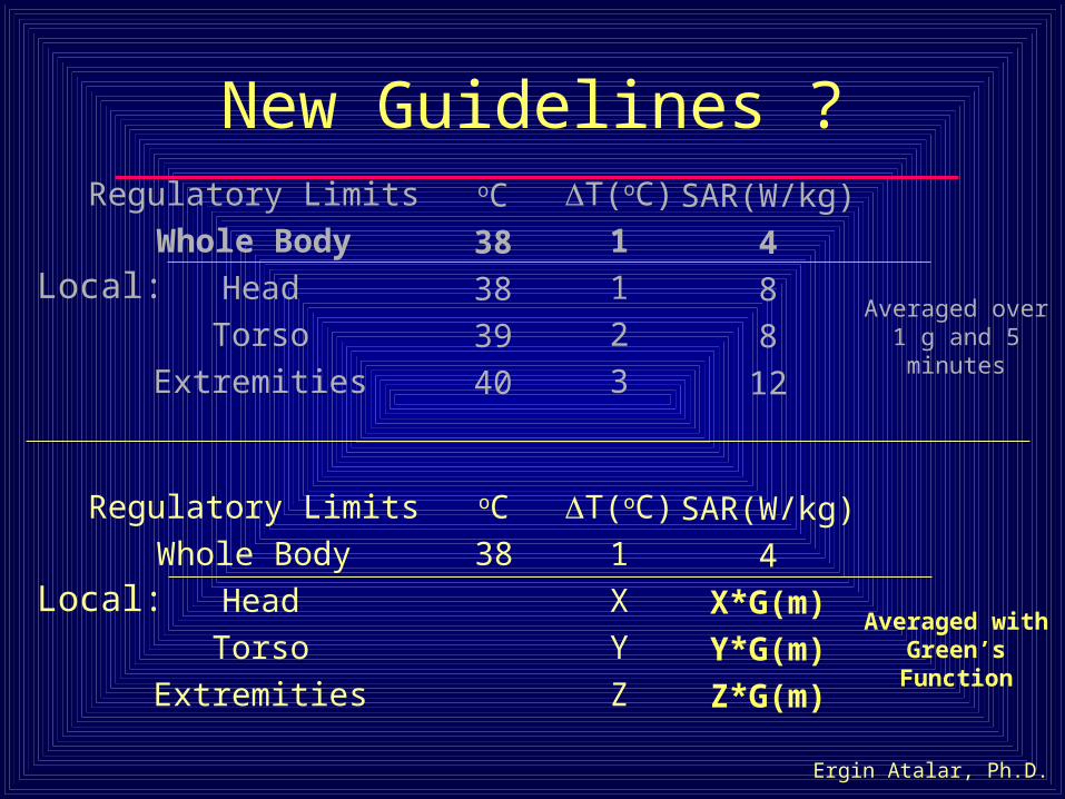
New Guidelines ?SAR(W/kg)
4
8
8
12
Regulatory Limits
Whole Body
Head
Torso
Extremities
oC
38
38
39
40
Averaged over 1 g and 5 minutes
T(oC)
1
1
2
3
Local:
SAR(W/kg)
4
X*G(m)
Y*G(m)
Z*G(m)
Regulatory Limits
Whole Body
Head
Torso
Extremities
oC
38
Averaged with Green’s Function
T(oC)
1
X
Y
Z
Local:
Ergin Atalar, Ph.D.
Summary - 1
• Using the Green’s function solution to the bioheat equation, established a rationale for updated guidelines for local RF heating
Ergin Atalar, Ph.D.
Outline
1. The coupled problem for 2 classes of internal devices (active and passive)
2. A metric for reporting the RF safety of a metallic device
3. A simple method for measuring the RF safety of a metallic device
Ergin Atalar, Ph.D.
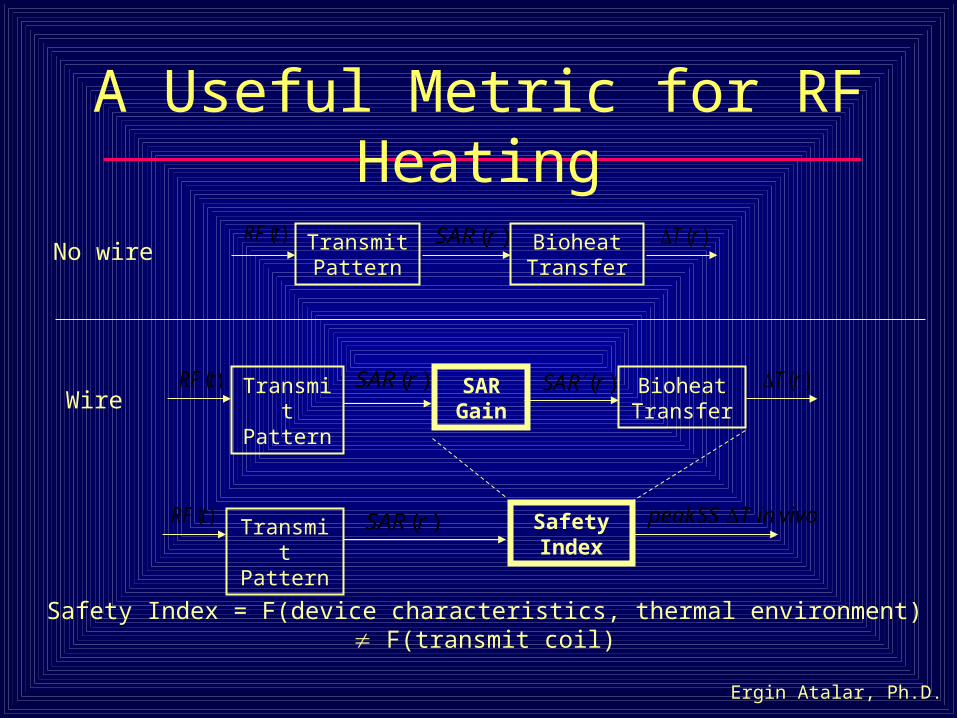
A Useful Metric for RF Heating
Safety Index = F(device characteristics, thermal environment) F(transmit coil)
Transmit Pattern
)(rSAR
Safety Index
vivoinTSSpeak ( )RF t
No wire
WireTransmit Pattern
)(rRSASAR
GainBioheat Transfer
)(rT
( )RF t )(rSAR
Transmit Pattern
Bioheat Transfer
)(rT
( )RF t )(rSAR
Ergin Atalar, Ph.D.
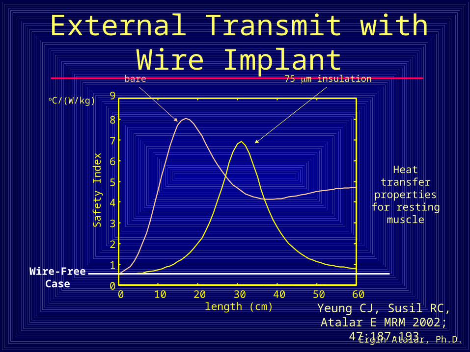
0 10 20 30 40 50 600
1
2
3
4
5
6
7
8
9S
afet
y In
dex
length (cm)
External Transmit with Wire Implant
oC/(W/kg)
bare 75 m insulation
Heat transfer properties for resting muscle
Wire-FreeCase
Yeung CJ, Susil RC, Atalar E MRM 2002; 47:187-193
Ergin Atalar, Ph.D.
1.4 2.7 10 27 54 1000
2
4
6
8
10
Saf
ety
Inde
x
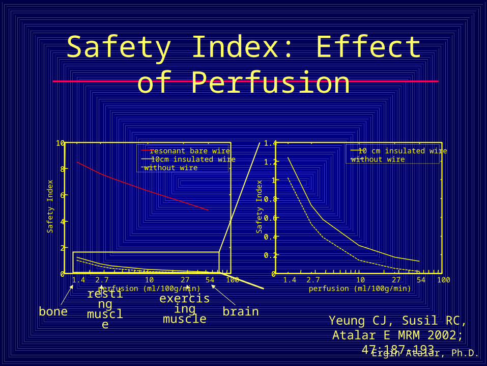
perfusion (ml/100g/min)
resonant bare wire 10cm insulated wirewithout wire
0
2
4
6
8
10
Safety Index: Effect of Perfusion
1.4 2.7 10 27 54 1000
0.2
0.4
0.6
0.8
1
1.2
1.4
Saf
ety
Inde
x
perfusion (ml/100g/min)
10 cm insulated wirewithout wire
0
0.2
0.4
0.6
0.8
1
1.2
1.4
boneresting muscle
exercising muscle brain
Yeung CJ, Susil RC, Atalar E MRM 2002; 47:187-193
Ergin Atalar, Ph.D.
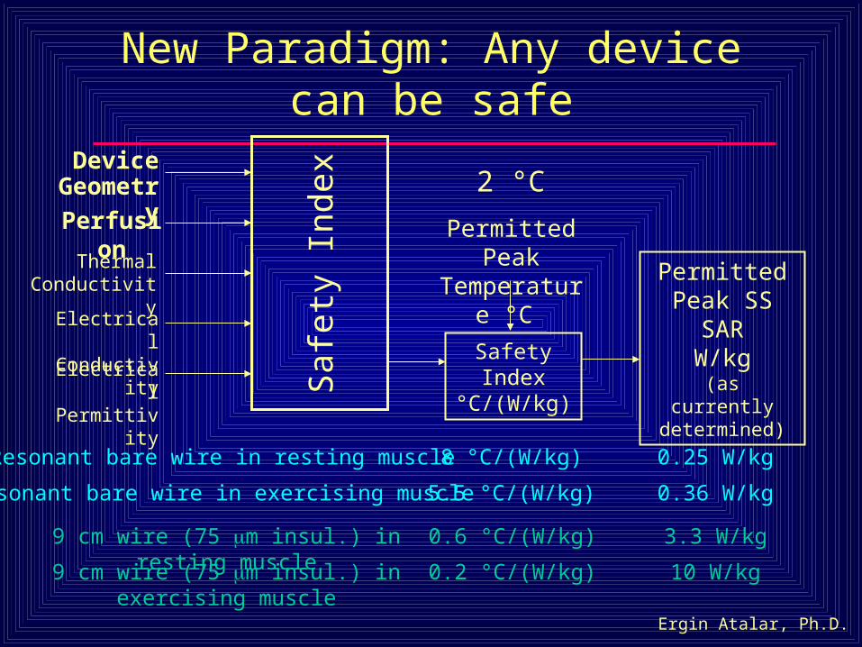
New Paradigm: Any device can be safe
Device Geometry
Perfusion
Thermal Conductivity
Electrical Conductivity
Electrical Permittivity
Safety Index °C/(W/kg)
Permitted Peak Temperature °C
Permitted Peak SS SAR
W/kg(as currently determined)
Saf
ety
Inde
x
Resonant bare wire in resting muscle 8 °C/(W/kg) 0.25 W/kg
9 cm wire (75 m insul.) in resting muscle 0.6 °C/(W/kg) 3.3 W/kg
2 °C
9 cm wire (75 m insul.) in exercising muscle 0.2 °C/(W/kg) 10 W/kg
Resonant bare wire in exercising muscle 5.5 °C/(W/kg) 0.36 W/kg
Ergin Atalar, Ph.D.
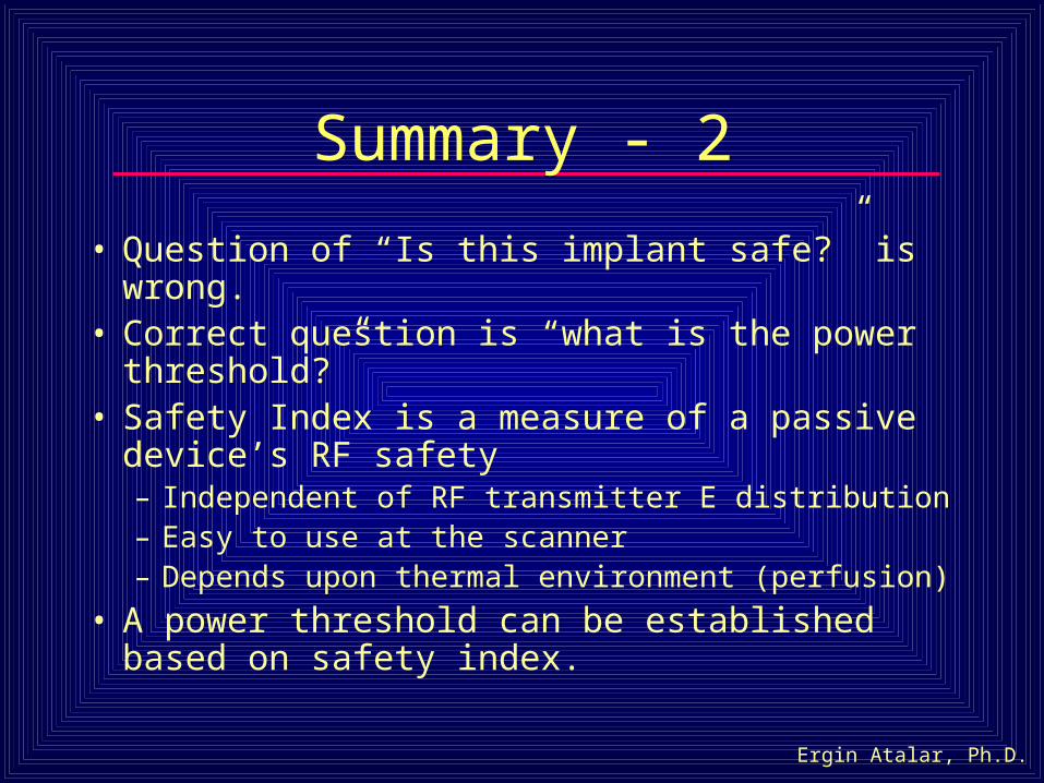
Summary - 2
• Question of “Is this implant safe?” is wrong.• Correct question is “what is the power threshold?”• Safety Index is a measure of a passive device’s RF
safety– Independent of RF transmitter E distribution– Easy to use at the scanner– Depends upon thermal environment (perfusion)
• A power threshold can be established based on safety index.

Ergin Atalar, Ph.D.
Outline
1. The coupled problem for 2 classes of internal devices (active and passive)
2. A metric for reporting the RF safety of a metallic device
3. A simple method for measuring the RF safety of a metallic device
Ergin Atalar, Ph.D.
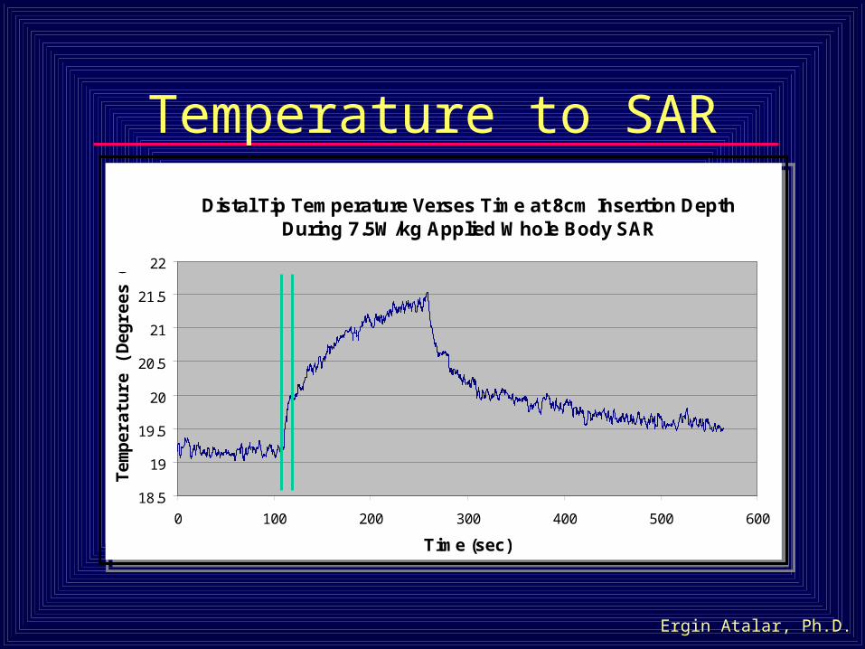
Temperature to SAR
Distal Tip Temperature Verses Time at 8cm Insertion Depth During 7.5W/kg Applied Whole Body SAR
18.5
19
19.5
20
20.5
21
21.5
22
0 100 200 300 400 500 600
Time (sec)
Tem
pe
ratu
re (
De
gre
es
C)
Distal Tip Temperature Verses Time at 8cm Insertion Depth During 7.5W/kg Applied Whole Body SAR
18.5
19
19.5
20
20.5
21
21.5
22
0 100 200 300 400 500 600
Time (sec)
Tem
pe
ratu
re (
De
gre
es
C)
Ergin Atalar, Ph.D.
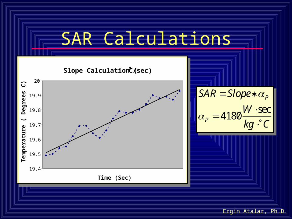
SAR Calculations
Slope Calculation (oC/sec)
19.4
19.5
19.6
19.7
19.8
19.9
20
Time (Sec)
Tem
per
atu
re (
Deg
rees
C)
sec4180
P
P
SAR Slope
W
kg C
sec4180
P
P
SAR Slope
W
kg C

Estimate In Vivo Temperature from Phantom Temperature Measurements
18.5
19
19.5
20
20.5
21
21.5
22
0 100 200 300 400 500 600
Time (sec)
Tem
per
atu
re (
Deg
rees
C)
Tvivo
: perfusion time constant
Ergin Atalar, Ph.D.
Summary - 3
• It is possible to estimate the in vivo temperature from phantom temperature measurements
• In vivo temperature value depends on the perfusion level
Ergin Atalar, Ph.D.
Conclusion
• New local RF heating guidelines
• Safety thresholds for internal transmitter and passive wires
• Safety Index – easy to use metric
• Simple measurement method
Ergin Atalar, Ph.D.
Acknowledgements
• Whitaker Foundation
• NIH Training Grant
• Surgi-Vision Inc.
• NIH R01 HL61672
• Christopher Yeung
• Rob Susil
• Xiaoming Yang
• Biophan, Inc.