rh ocean-bottom seismographic experiments telephone: … · navigation during the aleutian islands...
TRANSCRIPT

Distribution of thii document is unlimited.
AFTAC Project No. VELA T/7704 ARPA Order No. 624 ARPA Program Code No. 7F10
rH
OPERATIONS REPORT
ALEUTIAN ISLANDS EXPERIMENT
OCEAN-BOTTOM SEISMOGRAPHIC EXPERIMENTS
^S9 Prepared by
Joseph G. McDermott Edgar G. BeAbout and Staff
Ralph R. Guidroz, Program Manager Telephone: 1-214-238-4284
TEXAS INSTRUMENTS INCORPORATED Science Services Division
P.O. Boy -621 Dallas, Texas 75222
Effective Date of Contract; 5 April 1967 wontract Expiration Date: 31 July 1968
Amount of Contract: $1, 054. 991
ACKNOWLEDGMENT
This research was supported by the ADVANCED RESEARCH PROJECTS AGENCY
Nuclear Test Detection Office, under Project VELA UNIFORM
and accomplished under the technical direction of the AIR FORCE TECHNICAL APPLICATIONS CENTER
Contract No. F33657-67-C-1341
1 AS Ml ' Vv/ jli
31 January 1968
»rvlrt«« division
^

Distribution of this document 's unlimited. ••
^i AFTAC Project No. VELA T/7704 ARPA Order No. 624
*' ARPA Program Code No. 7F10
OPERA" ONS REPORT
ALEUTIAN ISLANDS EXPERIMENT
OCEAN-BOTTOM SEISMOGRAPHIC EXPERIMENTS
Prepared by
Joseph G. McDermott Edgar G. Be About and Staff
Ralph R. Guidroz, Program Manage: Telephone: 1-2)4-2^8-4284
£ TEXAS INSTRUMENTS INCORPORATED
Science Services Division P.O. Box 5621
Dallas, Tex^s 75222
Effective Date of Contract: 5 April 1967 Contract Expiration Date: 31 July 1968
Amount of Contract: $1,054,991
ACKNOWLEDGMENT
This research was supported by the ADVANCED RESEARCH PROJECTS AGENCY
Nuclear Test Detection Office, under Project VELA UNIFORM
and accomplished under the technical direction of the AIR FORCE TECHNICAL APPLICATIONS CENTER
Contract No. F33657-67-C-1 341
31 January 1968
science services division

^
0
ACKNOWLEDGMENTS
This research was sponsored by the Nuclear
Test Detection Office, Advanced Research Projects
Agency, Project VELA UNIFORM, under the techni-
cal direction of the Air Force Technical Applications
Center under Contract No. F33657-67-C-1341.
We wish to thank the Naval Station, Adak,
Alaska; Naval Communications Station; and Alaskan
Communications Region for their assistance in the
program. We would also like to thank the Air Wea-
ther Service for their monitoring and timely report-
ing of surfaced units.
c
c 11 scienc» ••rvle*a dlvlaiorf

J
ABSTRACT
An Ocean-Bottom Seismograph Aleutian Islands Experiment
was conducted during the summer of 1967. The objective of the experiment
was to obtain data for the determination of thickness and seismic velocities
of the crust and upper-mantle structure by deployment of three linear arrays
of instruments in the vicinity of Amchitka Island and by detonation cf a series
of chemical explosions.
Several tasks involved in the completion of the experiment
were equipment preparation, ship-rigging, shakedown cruises, and field
operations. In general, the OBS units and auxiliary equipment performed
reliably so that the experiment was completed with a minimum number of
problems within the specified schedule.
iii •clence services division
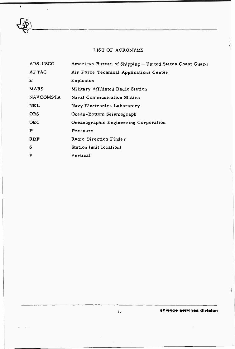
LIST OF ACRONYMS
AJiS-USCG
AFTAC
E
MARS
NAVCOMSTA
NEL
OBS
OEC
P
RDF
S
V
American Bureau of Shipping — United States Coast Guard
Air Force Technical Applications Center
Explosion
Military Affiliated Radio Station
Naval Communication Station
Navy Electronics Laboratory
Ocean-Bottom Seismograph
Oceanographic Engineering Corporation
Pressure
Radio Direction Finder
Station (unit location)
Vertical
IV soi«no» ••rvis«« division

.7
'J
TABLE OF CONTENTS
Section Title
ACKNOWLEDGMENTS
ABSTRACT
LIST OF ACRONYMS
I INTRODUCTION AND SUMMARY
II EXPERIMENT PREPARATION
A. OCEAN-BOTTOM SEISMOGRAPHS AND AUXILIARY EQUIPMENT
B. M/V VIRGO C. SHIP> RIGGING D. PORT ANGELES SHAKEDOWN CRUISE E. ADAK SHAKEDOWN CRUISE
III FIELD OPERATIONS
A. PHASE III
1. Stations 2. Explosion Program
B. PHASE II
1. Stations 2. Explosion Program
c. PHASE I
1. Stations 2. Explosion Program
D. NAVIGATION
1. Omega 2. Loran A 3. Celestial Navigation 4. Radar 5. Deadreckoning Navigation
E. COMMUNICATIONS
1. Radio and T(l-graph 2. Shipboard Inercom System
F. WEATHER
Page
ii
iii
iv
III
II-1
II-1
II-7 II-9 11-14 11-18
1II-1
III-2
in-;: III-4
III-9
III-9 III-13
ni-i4
111-14 III-17
III-19
III-19 111-27 111-27 111-27 111-27
111-28
111-28 111-31
111-31
I
■oi«no« ••rvio«s division
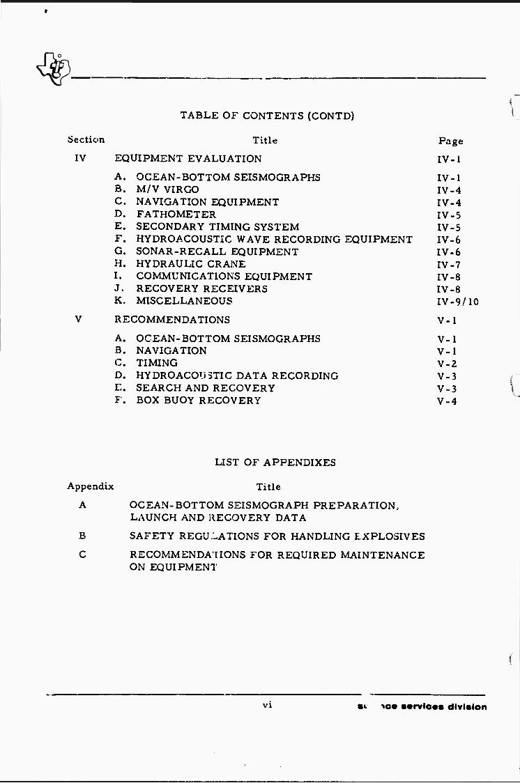
TABLE OF CONTENTS(CONTD)
Section Title Page
IV EQUIPMENT EVALUATION IV-1
A. OCEAN-BOTTOM SEISMOGRAPHS IV-1 B. M/V VIRGO IV-4 C. NAVIGATION EQUIPMENT IV-4 D. FATHOMETER IV-5 E. SECONDARY TIMING SYSTEM IV-5 F. HYDROACOUSTIC WAVE RECORDING EQUIPMENT IV-6 G. SONAR-RECALL EQUIPMENT IV-6 H. HYDRAULIC CRANE IV-7 I. COMMUNICATIONS EQUIPMENT IV-8 J. RECOVERY RECEIVERS IV-8 K. MISCELLANEOUS IV-9/10
V RECOMMENDATIONS V-l
A. OCEAN-BOTTOM SEISMOGRAPHS V-l B. NAVIGATION V-l C. TIMING V-2 D. HYDROACOUSTIC DATA RECORDING V-3 E. SEARCH AND RECOVERY V-3 F. BOX BUOY RECOVERY V-4
LIST OF APPENDIXES
Appendix Title
A OCEAN-BOTTOM SEISMOGRAPH PREPARATION, LAUNCH AND RECOVERY DATA
B SAFETY REGULATIONS FOR HANDLING EXPLOSIVES
C RECOMMENDATIONS FOR REQUIRED MAINTENANCE ON EQUIPMENT
VI •v to* ■•rvioas division
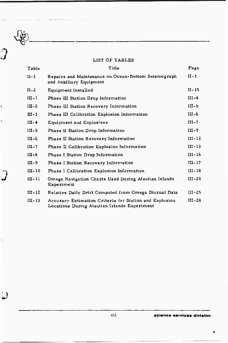
LIST OF TABLES
Table Title Page
II-1 Repairs and Maintenance on Ocean-Bottom Seismograph II-3 and Auxiliary Equipment
II-2 Equipment Installed 11-15
III-l Phase III Station Drop Information III-4
III-2 Phase III Station Recovery Information III-5
III-3 Phase III Calibration Explosion Information III-6
I1I-4 Equipment and Explosives III-7
III-5 Phase II Station Drop Information III-9
III-6 Phase II Station Recovery Information 111-12
III-7 Phase II Calibration Explosion Information III-13
III-8 Phase I Station Drop Information III-16
III-9 Phase I Station Recovery Information 111-17
III-10 Phase I Calibration Explosion Information III-18
III-11 Omega Navigation Charts Used During Aleutian Islands 111-20 Experiment
III-12 Relative Daily Drift Computed from Omega Diurnal Data 111-25
III-13 Accuracy Estimation Criteria for Station and Explosion 111-28 Locations During Aleutian Islands Experiment
vii sci«nc« ■•rvic«s division

LIST OF ILLUSTRATIONS
Figure Description Page
I-1 Aleutian Islands Exper" -nt Linear Arrays 1-2
il-l The M/V VIRGO 11-6
II-2 View of Deck of M/V VIRGO II-8
II-3 Engineering House Installed on Deck of M/V VIRGO 11-10
II-4 Hydraulic Crane Installed on Deck of M/V VIRGO 11-11
II-5 Nova Winch Installed on Deck of M/V ViRGO 11-12
II-6 Shooting Shack Welded to Deck of M/V VIRGO II-13
II-7 Charge Launch A-Frame Welded to Stern of M/V VIRGO 11-14
II-8 5-Ton Nitramon Charge 11-18
III-l Phase III Station Array III-3
111-2 Phase U Station Array III-10
III-3 Phase I Station Arr«.y III-15
III-4 Omega Diurnal Corrections, Adak, Alaska, 111-22 2 to 4 July 1967
III-5 Omega Dirunal Corrections, Adak, Alaska, 111-23 29 to 31 July 1967
III-6 Omega Diurnal Corrections Adak, Alaska, 111-24 28 to 30 August 1967
IV-1 Recording Periods, Aleutian Islands Experiment IV-2
VIXI •cl*no* ••rvloes division

J SECTION I
INTRODUCTION AND SUMMARY
An Ocean-Bottom Seismograph Aleutian Islands Experiment
was conducted during the summer of 1967. The objective of the experiment
was to obtain data for the determination of thickness and seismic velocities
of the crust and upper mantle structures by deployment of three linear ar-
rays of instruments in the vicinity of Amchitka Island (Figure 1-1) ?.nd by
detonation of a series of chemical explosions.
ment:
Several tasks were involved in the completion of the experi-
• Equipment preparation
o Ship-rigging
• Shakedown cruises
• Field operations
This report presents a detailed description of all phases
of the operations, as well as preliminary evaluations of operations and
instrumentation. DetaL was stressed so that guidelines for future similar
operations could be established using this report.
Equipment preparation (Section II) included the completion
of major repairs, necessary modifications and general cleaning of 14 Ocean-
Bottom Seismograph units and associated auxiliary equipment. Equipment
preparation was completed between 28 April and 8 June.
Ship-rigging involved the acquisition of a suitable vessel
and the installation of an engineering house and miscellaneous shipboard
equipment. The M/V VIRGO was selected for use during the field experi-
ment, and ship-rigging was accomplished in Port Arthur, Texas, between
12 and 2 0 May,
1-1 «cienc» services division

r-v'
0
''-i V, U3;
Q * $1 2 <
c. j
< fi m 5 ^ -J Ö z ^. S s W u * J
LL < ? a:
2 § uJ a 1 i;
< a- o 5
Si in » 1
• •
UJ o tn
-1 z QJ
< O
(3
< u (0
c
c
E
p.
W (0 •D c
3
0)
3 00
-I; -f
1-2 •oieno« ••rvle»s division

#■
;; Two shakedown cruises were conducted prior to the com-
mencement of the actual field experiment. The first was conducted in
PugetSou ^ on 17 and 18 June following the loading of the Ocean-Bottom
Seismograph units and auxiliary equipment on the M/V VIRGO in Port Ange-
les, Washington. The second was conducted off Great Sitkin Island on 8
July immediately before the actual field experiment began. During the
shakedown cruises, all equipment was checked out; and procedures for the
launch, recovery, and shooting operations were verified.
Field operations {Section III) were conducted in three phases
betwe' n 9 July and 13 September as follows:
• Phase III — 9 through 23 July
• Phase 11—24 July through 31 A ^ust
• Phase I — 1 September through 13 Siptember
During field operations, 31 uni s were deployed and 27 recovered (for a j
recovery rate of 87 percent), and thirty-five 5-ton chemical explosives
were detonated. A total of 314 complete or partial day^ of usable data was
recorded during the experiment, providing information for the completion
of the analysis portion of the experiment.
Navigation during the Aleutian Islands Experiment was im-
proved over that of previous experiments with the use of an Omega Navi-
gation system, a Loran A receiver, and radar fixes.
All equipment used during the field operations is evaluated
in Section IV, and recommendation for system and operations improvements
are presented in Section V. In general, the OBS units and auxiliary equip-
ment performed reliably so that the experiment was completed with a mini-
mum number ol problems within the specified schedule. Consequently, rec-
ommendations are mainly directed toward improving the accuracy of the data
(for example, timing and navitational information) collected during the experi-
J ment.
1-3/4 science servioes division

BLANK PAGE
gpjaaw J'HI.WHII ^m i jgfprJBW—WP 1 ■ • -. ' '»'" ■

i
/ t
SECTION II
EXPERIMENT PREPARATION
A, OCEAN-BOTTOM SEISMOGRAPHS AND AUXILIARY EQUIPMENT
Repair and general cleaning of the Ocean-Bottom Seismographs
and auxiliary equipment were necessary before beginning the Aleutian Islands
Experiment field operations. Under Task V of the Kurile Islands Experiment
(Contract F 33657-67-C-0105), minor equipment repairs were made, including
• Replacement of small O-rings
• Replacement o. calibiation-unit dry cells
• Replacement of back-up clock dry cells
• Minor repair of subsystems
• Minor repair of test equipment
• General cleaning of equipment
Major equipmen*. repairs resulting from weather, operational
environment, and unscheduled incidents during the Kurile Islands Experiment
were not included in Task V of the previous contract. Major repairs con-
ducted under Task I of the present contract included the following:
• Repair internal subsystems of units which leaked salt water
• Repair of unit 18, which washed up on the rocks during completion of Task I of the Kurile Islands Experiment
• Repair of unit 25, which floated in rough reas for several days
• Repair of auxiliary equipment which suiferea saltwater damage due to high winds and storms at sea
• Replacement of all Yardney SILVER-CEL batteries which were one or more years old
H-I science ss'-vicec division

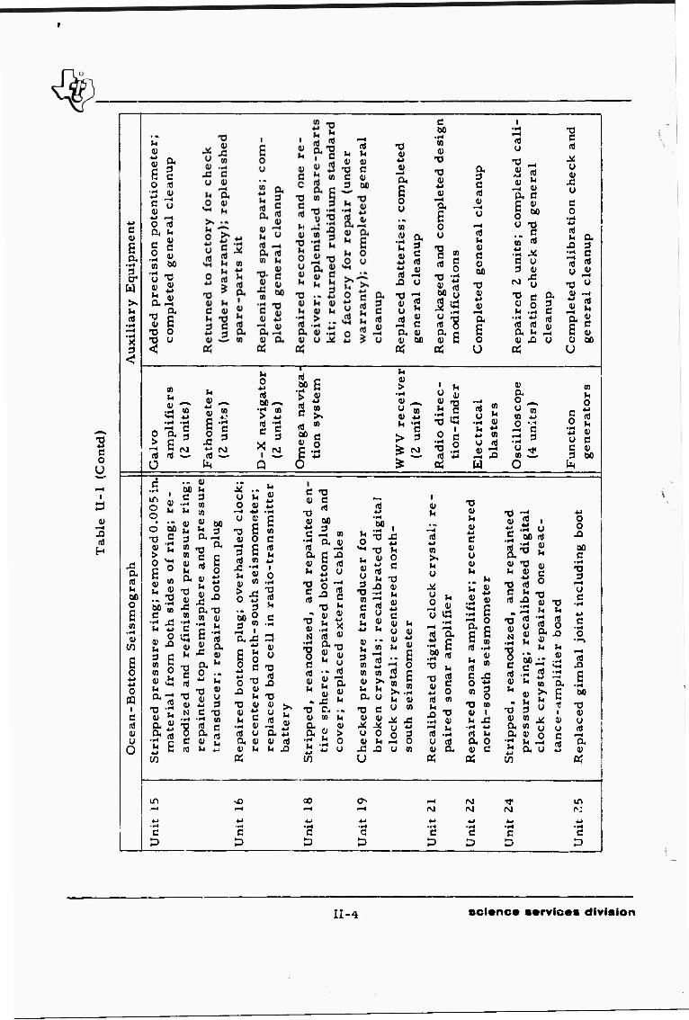
Specific repairs and maintenance completed during the Ocean-Bottom Seis-
mograph and auxiliary-equipment preparation are listed in Table II-1.
In addition to the repairs and maintenance performed on the
equipment, two modifications of the timing system were completed on the
Ocean-Bottom Seismographs. One change was the addition of more digital-
clock release times. In the past, the digital-clock configuration offered only
four unit-release times — 4, 10, 20, or 40 days after reset time. A field
program in which several units are dropped simultaneously or units are
dropped, recalled, and redropped on a tightly compressed time schedule re-
quires more freedom of choice in available release times. Therefore, the
digital clock was modified to provide clock releases I, 2, 4, 8, 10, 20, 30,
or 40 days after reset time.
The second change allows time pulses from the back-up clock
to be recorded. Previously, the only time reference recorded on magnetic
tape was digital clock time. Failure of the digitai clock renders the data
useless (in the case of complete breakdown) or at least increases the dif-
ficulty of analysis (in the case of repetitious time). Consequently, the Bulova
back-up clock, heretofore used solely for unit release, was modified so that
time pulses from the back-up clock could be recorded on the magnetic tape.
Pulses are superimposed on the north-south x 1 trace and have su'lciently
small amplitude to avoid interference with the seismic data on the trace.
The pulses are of different lengths and are placed on the tape at intervals of
10, 20, 30, 40, and 50 sec; 1, 5, and 30 min; and 1 hr.
Two additional items were added to the auxiliary equipment:
a secondary timing system and a magnetic tape recorder. Both items were
checked and integrated into the existing system. Secondary timing systems
were added because analysis of the data recorded during the Kurile Islands
Experiment revealed that the W ,VV signal recorded at unit reset and after
un't recall is often too noisy to supply an easily readable time reference.
JJ_2 scionce ••rvic«« ^vision

D
^j
H
t i CO
—4 i CO
c
E 0. 3 cr
W
u n)
~4 ■•i u a > (0 «
V Ü ti
—t
a (t
u
»
V iÖ 4-»
y
k
to
0 *J
CO •t-l
CO
c fl)
T3 V
•4J
4) -4
£ 0 u • * 4-1
c JÜ
<i u
XI 4J
4-1
c ner
al c
lean
up.
For
un
it 2
: nn
plet
ed g
ener
al c
lean
up
™ 4J
^H
T3 4)
4-1
n)
3 CO
C .r4
r-1
•iH
U
(X m
-o V U ri
-4
■*-»
0) i—«
i u
(U —t ,Q «J O
O 0
T3 4)
ti a
">. i-H
XI
£ 4) to CO
ti to tn <U c se
cone
and
fin
asse
mb
lies
; b
uil
t st
ora
ge
rack
, c
hec
ked
r
brok
^ n
or
dam
aged
cry
sta
4) 00 ti
£ nJ
n 4-> •F4
c 3
4) 4) >4
J3 4.»
-o V u n) yo
nd r
epai
r; r
epai
red o
ne
it;
rep
lace
d b
oth
cab
inet
s;
om
ple
ted g
ener
al c
lean
up o
n 11 u
nit
s
mp
lete
d g
ener
al c
lean
up
C 00
• fl ^^ n) 4)
u 0
u ■5 0 4-1
T3 4) ß »4 3
■o 4) 00 (Tf
£ d
0 4-»
(4
4) M
13 a
c
4)
E 0 ß
? ^4
(Ö 00 in T3
4> M
•■-1
ti a V
4)
£ ti #-l u rt 41 0 a- u ti O 4) a a 4) C *J E (4
1 0 JJ Q. 00 O V 0*JC c u & 4) Xi 3 U n) O V M-4
In & (X Ü 0J «4
^^ 4) 1 1 tn a 4J to CO 4^ 4) «! (4
ß CO
a nt CO
CO 4) •r4
XI
4J
JA u (Ti
j3 u 4)
o
4) 4>J
E
4-i
•a 3
CM
4->
(4
C 0
10
4> U "1
n 3
(4
4-J
n) •Sei
£ 4) CO tn rt)
(J
>> •—4
T3 M 0 U 4) M
U
»4
4) a (Ti
TJ
0 U 4)
to CO eg 04 CU 1
U u 4)
X S 0 m si
1
2 C
i u t
4) »4
3 CO
tn
1
a ft! nl o
»4
3 w 4)
01
c
4J U nl
3 CO
oc c
0 ^ ti •> o «
4) U
3 4;
4) U
nd r
epai
nte
d
sid
e-p
lug
re
d t
ransd
i
? 00
u
V
'»4
ti a 4)
4-> .r4 4~>
T3 M 4) (U C >
tn 4) »4
a ü 4)
3
a*
s .1-1 4J
u a.
u ti
--4
a,
3 T) to C
IT)
J3
•t-t
4) »4
a, ^4
--J 41 ti Li 4) Z U 4->
ß (Tl
4) >4
4) X! a tn
•F4
£ 4)
a d,
£ -ß DC 0
£ ."1 4)
W
6 0
0 PQ c
E 0
0
« 00
4) > 0
£ u in
14
1
0 oc c
•P4
u 1
t, op
CO 4)
^4
n)
£ 0 14
>*4
to
u
»4
3 to
14 4-1
4) »4
3 (0 CO <0 u a c 0
£ oo
iped
, r
ea.n
od
ized
, a
ir
e sp
her
e; r
ep
air
e
bott
om p
lug; re
pai
? 4) C
0 4->
(4
-§ ti
iS S to ^
ti
£ 0
^ U 4)
£ (4
a Ti 4J >
>*4
3 Ti »4
nt ^
0 0
4) < c
•f-l
to
4)
ti u
*-4
(t!
4)
3 to iO
4) *4 ..
£ (4
a C
u 1
O
U 4) C C 0 u o 'S
4J 44
£ o £
a 0 44
41 4-1
C
»4 V
a 4J
4)
M S) ß -M
■ r4 —<
n) • iH C 0- •« 00 00 ti ? U JJ 0 00 0 cn •r4
l 4) 1-4 a,5 £
c •r4
u U, ** "U c 2 c
•^ a) E c u • r-l
4) a a
0 «J VJ tf 4) a U a u S aj »4 )4 tn 4) k nj « Ä <j) « «
o ro 1—4 rg in —< «—< *-> «i 4-» 4J 4-t -rH •ri ■ »-» '-4 •r4
C c c c C D 3 D D D
II-3 science services division
c o U
^0 It H
c
s a. • •H
cr W >. M
o
0) to
o
I
c
1) u o
u 4)
c 4>
a 3 C IT)
V
u
nj TJ IH M v «) t) ■u
T3 ß 0) C a> CL 3 00 c
O <i
.2 «
a, "
0! £ •o o
c ■ r-l m 4)
T3
o u
m
H a 3
(1) c <-> n! ■u 1) rti f—i
J3 u
flj i-H
0) c
a 0) V OS
ttJ
a» OJ n)
^4 V a ^-* g u 0 —4
ü
"O -> V c 2 c n) g a 0 00 -o -43 *> ^ -o oo 3 4)
^ « 0) v. •■< ^-^
a. s 0
öS U
u
"1 a c § ^
- s to ™
■tJ X C U 3 4>
a 3 C
nj n) (u
4) Xi O
T3
0 to u 9)
(0
O >
Ü
t4
00 ^» fH in > 4-> m ■•*
rt C 3
I p
M
T7 2 w
fl) "» 00 e
O
> 4) U 4>
1 U u ; 4)
> 3
»4 g Ö
n) y
•■-1
(0
i M *■>
Ü c ■M a> ♦i-l 0 U m •u 1) n) 4-» JJ
w
a, o Ä U M
O
C
2 S
o
> 0
.. 4) 00 M C 3
•r< to « 3) (U «
-3 c
•H rj M u
O <U n U 3 £ to B to 0
a r! in
4)
00
3 a^ w g r 2 «> § a (u t;
T3 it 0
-Sax» « to 4)
<u 2 a
UM« O 4) S
^ i v o 3 S <T) to
a «J
2 £
T3 C n)
•O 4) N
.t-<
T3 O C
a * o .. « (4
73 « 4> "
4-1 3 C T3
J5 C
t/3
-C
> X!
.. 3 00 0
§ S 0 d
o -o
"U 4)
.2 4) rt y a 4)
05
to C
4-*
I
0
T3
Vi
(U u
TS
^3
e 'O V c
V 00 ♦^ 3 C ^ to
'S aÜ ag^j «4 U M 4J
-T 4)
- a. 'S
a JJ 4) «) U a3
3
4) U
4> " U .- tt)
U 4)
T3 a .« (U to M
CO
4) > O y
oo
t. 4)
to -<
u 2 4J (4
4> '* U w
'J5 4J to to 4) >» U U a y
T3 c V 4)
j»; x y o 4) M
x: u U
i
4-> u o c
T> 4) h 4)
4->
B 4) M y 4)
2 « - E
« E m o. It 4) U to
j<! x: u ti o 2 —i o u to
I 4) u
I»
>. y
x y o
T) 41 h 4)
4-> c 4) y 4) »4
(u 2 i « .tS y .S 00 nj
t u 4)
4) -O M 4)
X3 C
5 £ n) J3
a ^§
4-> O n) to
X> T Si (U
n) .S y n) 4) a
^ 0 x> N
0) .,4
to
g to ■
X! ■ r4 4J
a o V 3
'S c <i a u
y 4>
4i C o
X3 4) 14
-»4
«) a »4
'S B)
x y v
-C y
3 o
• f4 a it a
J3 3
y 2 -a u
4) -^ ** n) V >4
E 4) Ü 00
u
c o
■14 4->
y c 3
to u o 4-*
(T)
V c 4) 00
o o
00 c
•|4
x> 3
u ^ -4
^ 4-
§ .s -Q O
u __ « 13
^3 C ^J **-• — •c « - E
X> 3 " 4) to ^ a to (i a 4) o il a y 7)
a £ i 4J y 3
00
T3
u rt)
—4 a 4)
PC
m
c
vO
c D
00
c
t>
G
D
■ T4
c p
C
P
no in
c D
II-4 science services division

2 c o U
J3 rt H
13 ' a 5 >. .u d V rt ^3 ^ c f-i
i/ ,_ J3 rt 0 a a. «) -^ -5 91 , « 3 3 QO ™ u
5 fci J? C C rt "
ali
bra
tion c
sa
nup
en
era
l cle
a
en
era
l cle
a
0 unit
s d
am
com
ple
ted
an
d g
en
era
: 3 J
c
1 ssin
g a
nd
ple
ted g
en
3 0 ^ ^ 00 > i; ^ 6 1 W
>s hi le
te
ira
l
lete
lete
red
w
at
ehe
<J to C rt £ S E E ärtj
rt —< rt 0. 0 -^
•3 <
0 oo 0 0 u w £ 0) *J Ü
U U U « 0J >% h u V e «
igh
-fre
qu
ei
gen
era
tors
:ro
bo
tac
F d
um
my
lo
ad a
nd
w
att
nnete
r
olt
o
hm
me
(5 u
nit
s) CO
and to
ol
(2 s
ets
)
ffi to aJ > E
0) -o m » in »H
>. c !?. 3 w rt rt 2 g ^a^|^ w *» 'r1 ,„•*?-< 3W^<^0^M^^^3
J3 o>N'a,a<'Sn''^ CU ^«O-Ccn-C-rt 0
rt »4 DO 0
£ to
•t-l «
£ 0
nd t
ho
al
sub
nab
le
bat
te:
tenna
oth
er
:r,
am
I y
ear
eaned
a
b in
tern
q
uest
io
on-l
ight
aced a
n
les
and
alt w
ate
s over
]
ely c
l d
eaci
sd
all
b
eaci
;
repl
on b
a d
to s
tt
eri
e
rt v V v~* f * % * -!;-*n)rtJ'a)S-a 4; oU -H »^ _ 0 (j c<u ft-o IDJO a>- 0 Ou^«it«u(i;C
U to <-»
—. T3 -^ rt 3 C ti -■ 3
S.S = ai ^ «) ü
II-5 science services division
o Ü
>
4)
H
0)
M
II-6 science services division

1 Consequently, two Geotech Model 5400~A timing systems were supplied by
AFTAC and s it up as a secondary timing system. This system supplies a
readable time reference which can be recorded on unit a. gnetic tape and
can be easily chec ed against WWV.
Past field experiments revealed the need for increased record-
ing capability of hydroacoustic data during operations. Therefore, an Ampex
Model 300 tape recorder was supplied by AFTAC and used to record the cali-
bration explosion hydroacoustic data.
B. M/V VIRGO
An extensive search by TI personnel was conducted to find a
suitable vessel for the Aleutian Islands Experiment field operations , Factors
considered in the selection of the ship included availability, configuration,
ability to maintain a stable working platform, cost, and owner's experience
in marine operations.
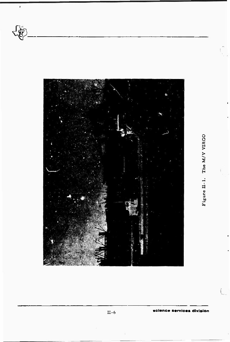
The M/V VIRGO (Figure II-1) was found to be the most suit-
able vessel for field operations and, along with a crew, was chartered from
Astro-Marine, Incorporated in Houston, Texas. The ship was designed for
deep-sea oceanographic research, and the large deck space (Figure II-2)
was adequate for program needs. Specifications for the M/V VIRGO are as
follows
Construction Welded steel hull, twin screw, double bottom and double chines; diesel pro- pulsion equipped with reverse and re- duction gears
Control Full pilot-house control
Length 165 ft
Breadth 36 ft
Depth 15 ft
Draft (full load) 11 ft
II. 7 science services division

Figure II-2. View of Deck of M/V VIRGO
II-8 science services division

1 Speed
Engines
Generators
Steering
Deck space
Certification
Electronics
Quarters
Liff;-saving equipment
Fuel capacity-
Endurance
C. SHIP-RIGGING
12 ki.ots (cruising speed); 14 knots (full-speed)
2 GM Model 16-567C, 1600 hp each
Two 100-kw, 120/280 v, 3-phase; driven by GM-871 diesels
Sperry gyrocompass with autopilot
4000 sq ft
ABS-USCG
400-fm recorder; radiotelephone; radio direction-finder; Decca RM-329 radar
9 ship crew; 19 scientific crew
Two 13-man inflatable rafts; life preservers; life vests- flares
57,000 gal
8000 mi or 30 days
The M/V VIRGO was outfitted for field operations in Port
Arthur, Texas, between 12 and 20 May. Ship-rigging included instal-
lation of the enginearing house, crane, firing-line reel. Nova winch, fathom
eter transducer, and A-frame.
The 45 x 25 ft engineering house stored at the Naval Inactive
Ship Maintenance Facility in Orange, Texas, since the completion of the
1966 Kurile Islands Experiment was placed on the deck of the M/V VIRGO
(Figure II-3). Installation involved
• Cutting down center legs so that house would fit on deck, installing doubiers under legs, and welding house to deck
• Welding padeyes on bulwark and securing house with turnbuckles
II-9 science services division

• Trimrring of'' tin around the bottom of building, installing angle iron around bottom of building, and waterproofing bottom of building by filling angle iron with cement
• Waterproofing roof of building, required after its removal to facilitate moving house onto the ship
• Welding platform behind the engineering house
• Sandblasting platform and painting platform and house as needed
• Installing eight double floodlights and four double switches for better lighting in house, installing larg-i circuit-breaker panel, and rewiring elec- triv.al circuits for optimum operation
FIRING-LINE REEL
ENGINEERING HOUSE
Figure II-3. Engineering House Installed on Deck of M/V VIRGO
II-10 science services division

*
./ A P&il Model H-312T fully hydraulic crane was installed on the
aft starboard deck (Figure II-4). Installation involved removal of the crane
from LJ carrier, fabrication of a suitable foundation, welding of the founda-
tion to the deck and the crane to the foundation, and the fabrication and weld-
ing of a boom rest. Specifications for the crane are as follows:
Boom length
Lifting capacity
Swing
Drum capacity
Cable feed control
Engine
Cab
27 to 62 ft
5 to 17 tons, depending on boom extension and operation radius
360°, 4 rpm
300 ft of 1/2-in. cable
Berger slack thrower
CM 4-53N, 4-rylinder diesel
All-weather, full-vision cab with safety glass windows
Figure II-4. Hydraulic Crane Installed on Deck of M/V VIRGO
II-11 science services division

The firing-line reel was mounted on the stack aft of the mast
(Figure II-3). Hydraulic equipment on the reel was removed and replaced
with an electric motor. A railing around the reel was fabricated and welded
to the stack, and a pipe ladder was mounted on the por*- side of the stack
from the deck to the reel. All necessary wiring, circuit breakers, and
switches were connected.
The Nova winch was welded to the main deck forward of the
stack (Figure II-5). Necessary wiring, circuit breakers, and switches were
c mnected.
NOVA WINCH
Figure II-5. Nova Winch Installed on Oeck of M/V VIRGO
11-12 selano« ••rvloas division

The ship was placed on drydock, and tht fathometer trans-
ducer was installed in the bottom of the vessel.
The shooting shack was welded to the deck and secured to the
port stern (Figure II-6). All necessary wiring, circuit breakers, and switches
were connected.
The charge launch A-frame was straightened and welded to
the stern (Figure II-7).
Four electrical outlets were installed, one cabinet was re-
located, and a plywood work table was placed on one of the bunks in the navi-
gation room. A yardarm with blocks and rope was welded to the aft mast-
Upo--. completion of ship-rigging, the M/V VIRGO left Galveston,
Texas, for Port Angeles, Washington, via the Panama Canal.
SHOOTING SHACK
CHARGE LAUNCH A-FRAME
BOX BUOY
Figure 11-6. Shooting Shack Welded to Deck of M/V VIRGO
11-13 science services division

CHARGE LAUNCH A-FRAME
Figure II-7. Charge Launch A-Frame Welded to Stern of M/V VIRGO
P, PORT ANGELES SHAKEDOWN CRUISE
The Ocean-Bottom Seismograph units and associated equip-
ment were shipped to Port Angeles, Washington, on 9 June in two vans de-
signed for transportation of electronic equipment. Equipment installation
and final ship-rigging were accomplished by Texas Instruments personnel
between 12 and 17 June. Equipment installed is listed in Table II-2.
11-14 •otonc« ••rvicas division

Engineering house
Navigation room
Radio room
Bridge
Playback room
Shooter shack
Taole 11-2
EQUIPMENT INSTALLED
Ocean-Bottom Seismographs, sonar-recall cabinets and transducers, secondary tim- ing sy tern, Ampex tape recorder, inter- com, and miscellaneous equipment and spare parts required to conduct the ex- periment; ex^ra anchors were secured under the engineering house
Omega navigation system, D-X navigator Loran A/C receiver, Hammarlund re- ceiver, fathometers, OEC handloop, in- tercom, and miscellaneous charts and maps
Collins KWM-2A transceiver, Collins 30L-1 linear amplifiers, R. F. Communications SB6FA transceiver, R. F. Communications RF 302 antenna coupler, Johnson match- box. Northern N620 auxiliary receiver, direction-finding unit. Cadre 510-A re- ceiver, intercom, ana miscellaneous spare parts
D-X navigator Loran A/C receiver. Cadre 510-A receiver, and intercom
Precision Instruments PI-214 tape recorder, Minneapolis Honeywell 906 Visicorder and 6-channel galvo amplifier, and miscellan- eous associated equipment
SCD-2000 BA-SIE blaster, Minneapolis Honeywell 906 Visicorder and 6-channel galvo amplifier. Specific Products WWVT 5-band receiver, and intercom
TI-15 science services division

Final ship-rigging consisted of the following:
• Mounting necessary antenna on the fore mast and connecting to the direction- finding equipment
• Mounting antenna on the aft mast and con- necting to the Omega navigation system
« Mounting 35-ft vertical whip antenna on the biw of the ship and connecting to the Collins radio equipment
• Mounting long-wire antenna between fore and aft masts and connecting them to the Loran A/C receivers and WWV receivers
• Welding additional padeyes to the aft deck of the ship for explosives cage tie-downs
• Connecting the individual intercom units into a workable system
• Secure all equipment for the shakedown cruise
A short shakedown cruise was taken on 17 and 18 June to run
preliminary checks on the equipment. Two units were looped in the Port
Angeles Bay on 17 June. The first system (unit 25) contained a Geo Space
HS-lU seismometer package, and the second system (unit 21) contained the
standard Electrotech EV-17 seismometer package. A line with a rubber
buoy was attached to each anchor.
The shakedown mission was undertaken in the mouth of Puget
Sound. Overcast skies and fog prevented the floating of a unit to check out
the radio direction-finder (RDF) equipment. However, a simulated charge
launch was completed to test launch and recording techniques. The capability
of the blaster to fire through the 6000 ft of firing line on the large reel was
verified. However, it was found that the firing-line feel had to be geared
down to prevent an overload on the electrical circuit.
11-16 sci*nc» ••rvic*s division

f
The fathometers and navigational equipment (Omega, Loran,
and radar) functioned properly during the shakedown cruise.
Unit 25 was recovered on 18 June by sonar recall with no
problems. The tide carried the buoy and unit 21 past the breakwater during
the night. The rope had broken, and the buoy was located about 5 mi from
the drop site. Sonar recall released the unit which was retrieved 1-1/2 mi
from the drop site. The unit did not sustain any damage due to this movement.
Retrieval of unit 21 provided an opportunity to test the RDF equipment and the
handloop. Some difficulty was experienced with the RDF equipment, but the
handloop functioned properly.
On 19 June, the ship was placed on drydock in Seattle, Wash-
ington, fcr repair of damage to the rudder and steering mechanisms caused yjY adverse weather conditions encountered on the voyage from Galveston,
Texas, to Fore Angeles, Washington. While in dryd-ck, the Omega naviga-
tion system, Ampex tape recorder, sonar-recall cabinets, and secondary
timing *' =«;em were secured using metal bands. Refueling and departure
from '.ne shipyard were completed on 21 June.
One hundred tons (twenty 5-ton charges) of Mitramon were
loaded and secured on 22 and 23 June at the E.I. DuPont de Nemours and
Company plant in Ta; oma, Washington (Figure II-8). Extreme tides (25 ft)
at the plant dock jmpiicated the explosives' loading. Excessive strain on
the O-ring hyr" aultc seals on the crane caused hydraulic leaks which per-
sisted thrr ghO'.c the project.
The M/V VIRGO departed for Adak. Alaska, on 23 June after
.! eqc'prnent and explosives were secured for the voyage.
H-ll science services division

SHOOTING SHACK BOX BUOY
5^ TON NITRAMON CHARGE
Figure II-8. 5-Ton Nitramon Charge
E. ADAK SHAKEDOWN C.1UISE
The M/V VIRGO arrived in Adak, Alaska, on 1 July. TI per-
sonnel arrived in Adak between 1 July and 3 July. The following tasks were
accomplished during the period 1 to 7 July:
• Established liaison with the Adak Naval Base facilities
• Installed la-id station (Texas Instruments portable seismograph) at the seismic vault operated by the U.S. Coast and Geodetic Survey
• Conducted thorough review of project ob- jectives, experim'ir;' procedures, and safety drills with ship's crew and TI per- sonnel
• Set up communications equipment and hv - perbolic Omega equipment in the quarter occupied by the port captain and port a - sistant in Adak
11-18 •ci«nce ••rvle*s division

I The final shakedown cruise was taken on 8 July. Unit 24 was
floated off Great Sitkin Island, and checks on the RDF equipment and hand-
loop were made. The RDF equipment did not function properly, but the hand
loop did. Navigational positions using Omega, Loran A, fathometer, and
radar agreed within ± 1 mi. One hydrophone was lost during the detonation
of a 4-lh test shot.
Analysis of the shakedown cruise showed that overall ability
of personnel to handle operations was greatly improved.
11-19/20 science services division

BLANK PAGE
r-:M^^M
SECTION III
FIELD OPERATIONS
The objective of the Aleutian Islands Experiment field opera-
tions was to obtain data for the determination of thicknesses and seismic
velocities of the crust and upper-mantle structures of the Aleutian Arc by-
deployment of three linear arrays of Ocean-Bottom Seismographs and deto-
nation of a series of 5-ton chemical explosions. All three linear arrays
were referenced to a point on Amchitka Island (51o3r00,,N, 179o37,00"E)
and placed on a line running N42 E and S42 W from the reference point.
Two of the arrays (Phase I and Phase III) were designed to
obtain information on the crustal structure in the region of Amchitka Island.
The third array (Phase II) was designed to obtain information on the upper-
mantle structure between 1800 km south and 800 km north of the island.
Phase II was planned in conjunction with the CHASE VI experiment, a 1. 5-kt
chemical explosion scheduled for detonation at 51o12,00"N, 178o26l00"E.
Field operations, consisting of a total of 31 instrument drops
and thirty-five 5-ton explosions, were completed between 9 July 1967 and
13 September 1967. Individual phase periods are as follows:
• Phase III, 9 July to 23 July
• Phase II, 24 July to 31 Aug st
• Phase I, 1 September to 13 September
Appendix A is a typical li^t of preparation, launch, and r«--
covory data prepared tor unii. 21.
TTTI science services division

A. PHASE IU
1. nations
The Phase III station array consisted of 10 units spaced 20 km
apart from 20 km to 200 km N420E of Amchitka island (Figure UI-l). Unit
placement w? s accomplished between 10 and 12 July. Station S25 was placed
west of Semlsopochnoi Island off the array line. Unit 16 was initially dropped
at location S2b bat resurfaced almost imm .diately. Investigation revealed
that failure of a ceramic capacitor in the Eu'ova back-up clock circuit pro-
duced a short whRn activated the release mechanism. All other units were
deployed without problems. Unit drop information is presented in Table III-l
Prime recovery operat'cns fc- Phase III stations were con-
ducted between 20 and 23 July. Eight units were recovered by sonar recall
during the period (Table III-2), Two units (unit 10 at S29 and unit 2 at S32)
failed to respond to sonar recall. Subsequent searches vi the areas on 3 1
July, 1 August, and 24 August for possible clock recall were conducted with
negative results.
Some difficulty was encountered with sonar recall rf units at
shallow depths (s 60 fm). It was often necessary to pass directly over the
unit before the unit would release from the anchor. Various output levels
and transducer depths were ised in the recovery operations. In general, it
was found that shallow instruments should be recalled using low power output
and a deep transducer.
Transmitters Jid not operate immediately after unit surfacing
at two locations — S23 and S26. In both cases, initial sighting was visual,
and the transmitters did not begin operation until the ship was alongside the
unit. Preiiminar/ investigation as to the cause of transr ission delay indi-
cates wet Mecca connectors between the unit and the antenna, « onpleting the
saltwater transmitter snort.
Ill-2 •cience sarvices division

+ 0
.<?
•EZI
*€M
■t»
'«• •tfT
/ • SM
-931 •no
j «s» «528
.SÜ7
" ■' x-r \ ,SSJ* ^- :_ .«3
•""?
^•^w >»
'EM : .--"•" it26
2o:o
^0-
ALEUTIAN
,Si5
ALEUTIAN ISLANDS NORTH PfiCi^iC OCEAN
OB SEi? OPERATIONS_!26I_
Sco» •! I,l2e.}2l »•) C8G; SK.2
• "9€^ Urn' Lototion • fiD'Ciro^ Loeol^f
Figure III-l. Phase III Station Array
III-3 science services division

* Table III-l
PHASE III STATION DROP INFORMATION
Station Unit Drop Date
(GCT) Location
Latitide Longitude
Est. Accuracy
(mi)
Water Depth
(fm)
S23 24 10 July 51o4J,00"N 179o09,30"E ± 1/2 460
S24 1 10 July 51o51,00"N I7902r24"E ± 1/2 325
S2.S 15 10 July 52o02,50"N 179023,54"E ± 1/2 101
S26 18 11 July 52o05,06,,N I79044,24"E ± 111 32
S2 7 19 11 July 52o13,00"N 179o56,00"E ± 1/2 36
52 8 20 11 July 32o2r00"N 179o50,40l"W ±3/4 95
S29 10 12 July 520t9,36"N 179o40,54"V/ ±3/4 62
S30 22 12 July 52o38,00"N 179o27,00"W ± 3/4 60
S31 21 12 July 52o46,30"N 179012,24"W ± 3/4 862
S32 2 12 July 52t53'54"N 179o01,48"W - 3/4 1749
Operation of the tape recorder in unit I at S24 was "jerky", the
tape being pulled intermittently during the entire recording period. No usable
data were recorded by the unit. The trouble source was traced to a worn bearing.
2. Explosion Program
The Phase III explosion program consisted of eleven 5- con chemi-
cal explosions — eight explosions between 220 km and 360 km N42 E of Amchitka
Island (E 1 5 through E22) and three explosions between 40 km and 80 km 542° W
of Amchitka Island (E24, E25, and E26). The explosion program wa^ conducted
between 16 and 20 July. Phase III explosion locations are presented in Figure
III-l, and Table III-3 contains pertinent calibration explosion information. All
shot depths were computed from hydroacoustic data. A detaPed report on shot-
depth determination is presented in the preliminary analysis report under ne
present contract. All Phase III explosions were detonated without a misfire.
Equipment and explosives involved in each explosion are presented in Table III-4.
Texas Instruments Incorporated, 1968: Preliminary Analysis Report — Aleutian Islands Experiment, Ocean-Bottom Seismographic Experiments, Contract
No. F33657-67-C-1341, 31 Jan.
III-4 science services division

Table III-2
PHASE III STATION RECOVERY INFORMATION
[ Component Oper.
i
Sta. Unit Recall Method
Trans- mitter
Beacon Light Remarks
S23 24 Sonar No Yes Transmitter began working when unit was alongside ship
S24 1 Sonar Yes Yes Tape recorder operation jerky; no usable data recorded
S25 15 Sonar Yes Yes Beacon light apparently working throughout recording period
S26 18 Sonar No Yes 4-hr attempt at sonar recall on 21 July failed; second attempt on 23 July suc- ceeded. Transmitter began working when unit was alongside ship
S27 19 Sonar Yes Yes —
S28 20 Sonar Yes Yes Seismometer package appeared tilted teZQ0
S29 10 Unit not recovered. Sonar recall at- tempted on 21 and 22 July; search of area on 31 July, 1 August, and 24 August for possible clock recall also negative
S30 22 Sonar Yes Yes Seismometer package appeared tilted about 45 ; release mechanism bent when unit separated from anchor
S31 21 Sonar Yes Yes —
S32 2 Unit not recovered. Sonar recall at- tempted on 22 July; search of area on 31 July, 1 August, aid 24 August for possible clock recall also negetive
III-5 science services division

Table III-3
PHASE III CALIBRATION EXPLOSION INFORMATION
Event
Event Depth
(ft) Date
(1967)
Detonation Time
(GCT)
Location
Latitude Longitude
Eat. Accuracy
(mi)
Water Depth (fm)
E15 747 16 July 20:48:05,4 53o00,12"N 178<,46,12"W ± 3/4 1930
E16 755 17 July 02:20:06.1 53<,09,12"N 178,,37,06"W i 3/4 2000
E17 671 17 July 7':03:04.8 53014,48"N 178o24,50"W ± 3/4 2015
E18 678 18 July 01:06:05.4 53024,42',N 178,,12»3Q"W ±3/4 2020
E19 679 18 July 03:30:05.5 53o31,20"N 178o00,00"W ±3/4 2028
E20 665 18 July 06:21:05.4 53o39'06"N 177o46,00"W ± 3/4 2030
E21 664 18 July 23:25:05.5 53045,54,,N 177032,54"W ± 3/4 2035
E22 672 19 Tuly 02:37:05.2 sa^'so-'N 177,,20,36"W 1 3/4 2035
E24 670 20 July 00:32:05.6 5ri6,40"N 178035,24"E ± 3/4 760
E25 657 20 July 05:05:05.4 5lo10'30,'N 178o20'30,'E ± 3/4 1925
E26 659 20 July 07:50:05.5 Sl'Ol'WN na'lO'AS'E ± 3/4 1785
Explosion-detonation safety procedures were established
before commencement of the experiment and were followed throughout
the experiment (Appendix B). During the explosion preparation, launch,
and detonation, specific steps are followed.
First, the charge is placed on the A-frame with about 1 ft of
the cage extending over the stern of the ship. The charge is secured by chains
connected to padeyes on the deck, and the harness is tied to the top of the
charge. Then, the charge-support rope is tied to the harness and the box
buoy; and the line buoys are tied to the charge-support rope. The box buoy
is launched using the crane, and the ship pulls ahead slowly until the box
buoy and charge-support rope are floating directly behind the ship.
All radar and transmitting equipment are turned off and secured
after a radar sweep is made to determine if any ships are in the area. Then,
the shooter and safety engineer proceed to the explosives magazine and re-
move the necessary primers, boosters, and caps.
III-6 sctonce services division
Equipment
Box buoy
«/
Charge support rope
Line buoys
Charge harness
Main charge
Primers
Boosters
Caps
Firing line
Blaster
A-frame
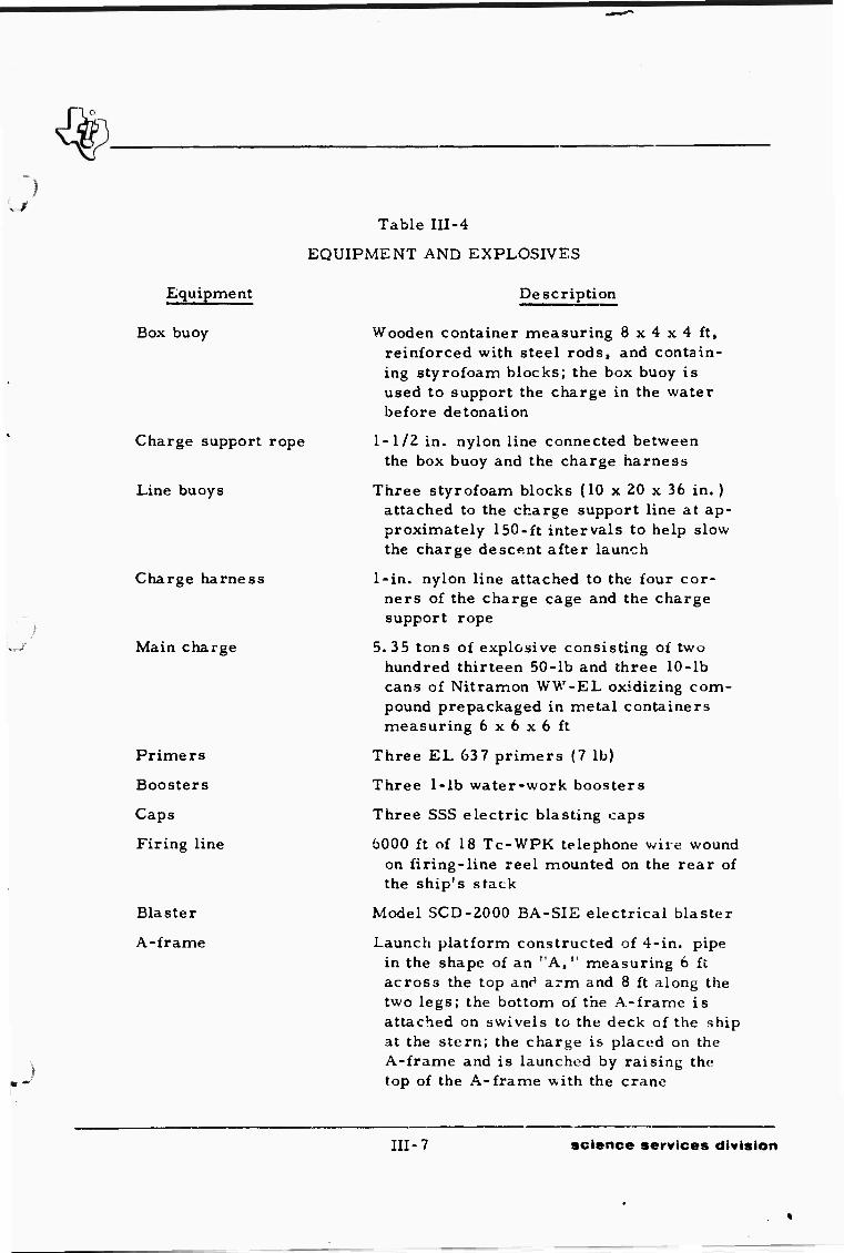
Table III-4
EQUIPMENT AND EXPLOSIVES
Description
Wooden container measuring 8 x 4 x 4 ft, reinforced with steel rods, and contain- ing styrofoam blocks; the box buoy is used to support the charge in the water before detonation
1-1/2 in. nylon line connected between the box buoy and the charge harness
Three styrofoam blocks (10 x 20 x 36 in. ) attached to the charge support line at ap- proximately 150-ft intervals to help slow the charge descent after launch
1-in. nylon line attached to the four cor- ners of the charge cage and the charge support rope
5. 35 tons of explosive consisting of two hundred thirteen 50-lb and three 10-lb cans of Nitramon WW-EL oxidizing com- pound prepackaged in metal containers measuring 6 x 6 x 6 ft
Three EL 637 primers (7 lb)
Three 1-lb water-work boosters
Three SSS electric blasting caps
6000 ft of 18 Tc-WPK telephone wire wound on firing-line reel mounted on the rear of the ship's stack
Model SCD-2000 BA-SIE electrical blaster
Launch platform constructed of 4-in. pipe in the shape of an "A," measuring 6 ft across the top and arm and 8 ft along the two legs; the bottom of the A-frame is attached on swivels to the deck of the ship at the stern; the charge is placed on the A-frame and is launched by raising the top of the A-frame with the crane
III-7 science services division

The blasting "aps ara placed in the lead-lined safeiy box,
checked for continuity, and competed co the firing line. The primers,
boosters, and caps are placed in th charge cage, making the charge armed
and ready for launch.
Next, the chains are remo ed from the charge, the A-frame
is tilted, and the charge is launched. The thip pulls away using one engine,
and the firing line is reeled out. When approximately 3500 ft of firing line
has been reeled out, the ship is stopped, the radar is turned on, and a sweep
is made to insure that no ships are in the area. Then, the charge is detonated.
After detonation, the firing line is reded in and all equipment
secured on the back deck. The box buoy and charge-support rope are re-
trieved.
Hydroacoustic data are recorded using a hydrophone attached
to the box buoy and two hydrophones hung over the side of the ship. Equip-
ment used to record the hydroacoustic data follows:
• Geo Space MP-8 pressure-sensitive hydrophones
• Texas Instruments dual-hydrophone sensor
• Specific Products WWVT 5-band re- ceiver
• Minneapolis Honeywell 906 12-channei Visicorder paper recorder
• Minneapolis Honeywell 6-channel galvo amplifier
• Ampex 300 series FM carrier magnetic tape recorder (modified as per 508234)
• No. 6145-243-8466 assault-wire signal cable
HI.g science service.« ct^vltcion

B. PHASE 11
], Stations
The Phase II station array consisted of 11 units, six between
50 km and 500 km N42CE of Amchitka Island and five between 600 km and
1400 km S420W of Amchitka Island (Figure III-2). The northern stations
were deployed between 24 and 26 July. Stations to the south of Amchitka
Island were deployed between 4 and 6 August. Unit drop information is pre-
sented in Table III-5. No major problems were encountered during Phase II
static n deployment.
Table III-5
PHASE II STATION DROP INFORMATION
Station Unit Drop Date
(GCT) loc
Latitude ation
Longitude
Est. Accuracy
(mi)
Water Depth (fm)
Sll 16 24 July 51o50,00"N 179o21,30"E ± 1 320
S12 21 Ü5 July 52012,48"N 179055,42"E ± 1 36
S13 5 25 July 52o5r06"N 179o03,24"W ± 1 1500
S14 22 26 July 53o32,0n"N 178CJÜ,00"W ± 1 2030
Si5 20 26 July 54o10,06"N 176058,00"W ± ; 2025
S I 6 15 26 July 54047I43MN 175o50,30"W ± i 2000
SI 7 24 4 Aug. 47024I48"N 173036,24"E ± i 276{
S18 18 5 Aug. 45o59,00"N 172o02l48"E ± i 3020
S19 1? 5 Aug. 44o30l3ö"N 170o26,54,,E ± i 720
S20 6 Aug. 43o03,48"N 169o03,54',E ± 1 1/2 2740
S21 25 7 Aug. 41034,36"N 167042,12"E ±11/2 2840
III-9 science services division

10 5i
if.
•"•
_ o
S vt
2 in
Figure III-2. Phase II Station Array
III-10 science services division

J Primary recovery operations for Phase 11 stations were con-
ducted between 12 and 20 August. Ten units were recovered by sonar recall
during the period, and one unit (unit 5 at S13) failed to respond to sonar
recall (Table 111-6). All of the units deployed on the southern leg of the ar-
ray (SI 7 through S21) were recovered between 12 and 17 August.
Transmitters did not operate immediately after unit surfacing
at two locations (S18 and S20). Recall of unit 18 at S18 was attempted during
the day, but the search was abandoned after 6 hr with no signal from the unit.
After the remainder of the 'mits along the southern leg were recovered, the
ship returned to S18. Both the handloop and the Hammarlund receiver picked
up the signal from unit 18, and the unit subsequently was retrieved 14 mi
east of the drop site. Unit 13 at S20 was recalled at night and was retrieved
easily with the aid of the beacon light.
Five of the units on the northarn leg of Phase II operations
responded to sonar rec .11. Sonar recall of unit 5 at S13 on 18 August proved
unsuccessful. A subsequent search of the area on 24 and 25 August for pos-
sible clock recall also proved unsuccessful.
The transmitter on unit 20 (S15) operated intermittently after
surfacing, although the unit did transmit long enough to determine that the
unit had surfaced. The unit was recalled at night, but stormy weather de-
layed sighting the beacon light.
Beacon lights on units 21 and 15 (S12 and S16) did not operate
upon surfacing. Both units were recalled and recovered during daytime, and
both transmitters functioned properly. Batteries had been removed from the
unit 21 beacon light (S12) before the unit drop because of shallow water (36 fm)
and scheduled length of the drop (30 days). The beacon-light pressure switch
does not activae above a depth of 100 fm; battery power for the light would
have been drained during the first 2 weeks. A battery wire on unit 15 (SI 6)
was pinched between the light case and the top hemisphere of the unit causing
an operational failure.
Uj- 1 1 science services division

Table III-6
PHASE II STATION RECOVERY INFORMATION ——
Component Oper.
Sta. Unit Recall Method
Trans- mitter
Beacon Light Remarks
SU 16 Sonar Yes Yes —
S12 21 Sonar Yes Beacon light batteries not placed in unit because of drop depth (36 fm) and length of recording period
S13 5 "■•• —" "■" Unit not recovered. Sonar recall at- tempted on 18 August; search of area on 24 and 25 August for possible clock recall also negative
S14 22 Sonar Yes Yes —
S15 20 Sonar No Yes Unit recovered at night; transmitter intermittent until unit alongside ship
S16 15 Sonar Yes No Beacon light not working because of pinched battery wire
517 24 Sonar Yes Yes Recorder take-up reel not functioning properly, but recorder pulled tape which collected in bottom pan
S18 18 Sonar No Yes Unit released by sonar recall on 12 August, but transmitter not operating; transmitter operating upon return to area on 17 August. Unit recovered 14 mi from drop site
S19 19 Sonar Yes Yes —
S20 13 Sonar No Yes Unit recovered at night; transmitter intermittent until unit alongside ship. Tape playback revealed all channels dead; no usable data recorded during drop
S2l 25 Sonar Yes Yes
Ill-12 science services division

I /
Shipboard playback of the tape from unit 13 (S20) revealed that
the digital clock and 12. 5-Hz reference-trace channels were dead. The unit's
digital clock was changed and checked. Subsequent playback of the tape from
unit 13 revealed that all channels were essentially dead, with only occasional
large signals appearing on the P and V channels. No usable data were re-
corded during the drop. The reason for the malfunction was not determined;
no malfunctions were noted on test tapes recorded by unit 13 before the drop
at S20 and after recovery.
2. Explosion Program
The Phase II explosion program consisted of eight 5.35-ton
chemical explosions — three explosions between 600 km and 800 km N420E
of Amchitka Island (E12 through E14) and five explosions between 500 km and
1500 km S42ÜW of Amchitka Island (E9 through Ell, E27, and E29). Phase II
explosion locations are presented in Figure III-2; Table III-7 contains per-
tinent calibration explosion information. All shot depths were computed from
hydroacoustic data. A detailed report on shot-depth determination is
presented in the preliminary analysis report under the present contract.
Explosions E12 through E14 were detonated on 27 July after
deployment of the stations along the northern leg of the Phase II layout. The
explosions were detonated without a misfire.
Table III-7
PHASE II CALIBRATION EXPLOSION INFORMATION
Event Depth Date
Detonation Time
Location list. Accuracy
Water Depth
Event (ft) (1967) (COT) Latitude Longitude (mi) Km)
3040 E9 623 7 Aug. 21:35:03.8 40°04,42"N lh6°Z3,36"E 111/2
E10 608 9 Aug. 03:55:02.2 42017,f4"N 168°19'06"E ill/2 2890
Ell 603 11 Aug. 00:25:01.8 45°44,00"N 17l''40,42"E 3085
E12 642 27 July 20:30:05.2 56°3!,36"N 172',15'54'W 520
£13 631 27 July 07:31:05.6 56°03,12"N 173029,48,W 1775
EM 631 27 July 01:40:05.3 55°24,18"N 174°44,,24"W 1955
E27 629 8 Aug. 04:40:03. 7 40°5I'36"N 167o02'18' E 111/2 2<*70
E29 615 11 Aug. 20:36:02.2 48°0;'40"N I74°27,30"E 1 ' 2850
III-13 •oi*nc« ••rvicas division

The remainder of the Phase II explosions were detonated be-
tween 7 and 11 August after deployment of the stations along the southern
leg of the Phase II .layout. The explosive program was de'ayed during the
CHAS.F] VI countdown and was resumed after sufficient information was re-
ceived indicating that the CHASE VI detonation would not be accomplished
within the time-frame of th i OBS Phase II operation. It was anticipated
that the data recorded from the CHASE VI experiment would alle v a gross
determination of the island arc's upper-mantle structure. The failure tc
receive data from the CHASE VI experiment leaves only information ob-
tained from the OBS calibration explosions which were not expected to pene-
trate the mantle.
The first attempt to detonate explosion E10 resulted in a mis-
fire. Standard procedures were employed to cut the charge from the box
buoy. The ship was backed to within 1/2 mi of the box buoy, and another
at; -Tipt was made to detonate the charge. Since the charge did not detonate,
the firing line was cut and the ship pulled away. Next, the ship was eased
up to the box buoy. A 25-ft loop of chain was connected to the crane hook,
and the chain loop was thrown over the box buoy and allowed to fall past the
buoy into the water. Using the crane, the chain loop was pulled up, exposing
the top of the charge-support rope. The charge-support rope then was cut
using a sharp knife atiched with meii.1 clamps to a boat hook. This procedure
allows the charge tö sink to the bottom, where pressure and salt water cause
rapid deterioration of the individual cans of Nitramon. In no way do the re-
leased charges poce a hazard to navigation.
C. PHASE I
1. Stations
The Phase I station array consisted of 10 units spaced 20 km
apart from 20 km to 200 km S420W of Amchitka Island (Firure Ill-i). Units
were deployed between 31 August and 3 September. Unit Irop informat'.on
is presented in Table Iii-8. No major problems were encountered during
Ph.. se I station deployment.
111-14 science sarvices dlvisior

1
sit
■ES 5S9 A ET
%4 'S3
140
h
87
S9 E34,ESSA SIO
EI.EM.E»? El
E3 C4
i ES
E«
* *E3e ESI
ESt
E33
~LEUTI/.--l
ALEUTIAN ISLANDS NOFTH PACIFIC OCEAN
OB SE.S OPEfiATI0NS_i267_
Scale -1 i,l26.Ki Ref C9GS 9(02
Legend
• I9v, U"'» Loco»>oi • Eiplo^on Locol'cn
Ctn'o^'t ff ^ •
Figure III-3. Phase I Station Array
III-15 science services division

Table 111-8
PHASE I SfATION DROP INFORMATION
Station Unit Drop Date
(GCT) I.
Latitude ation
Longitude Est.
Accuracy (mi)
Water Depth (fm)
SI 21 31 Aug. 5l025'lZ"N 178o45,00"E ± 1/2 187
S2 19 1 Sept. 51016,24,,N 178o3r,00"E ± 111 765
S3 13 1 Sept. Sl^'lS'-N 178o20,24"E ± 1/2 19-u
S4 1 1 Sept. S^Ol'OC'N 178o06,48i,E ± 3/4 1748
S5 20 1 Sept. 50o53,15"N 177059'42,,E ± 3/4 2580
S6 18 2 Sept. 50o45,00nN 177o46,00"E ±3/4 2980
S7 15 2 Sept. 50o36,20"N 177o37,00"E ±3/4 3840
S8 22 2 Sept. 50o26,12"N 17702^'42,,E ±3/4 3150
S9 24 2 Sept. 50o20,42"N 177013,12"E ±3/4 2850
S10 25 3 Sept. 50olll48,,N 177''02,12,,E ± 3/4 2690
Primary recovery operations for Phase I stations were con-
ducted between 9 and 11 September. Eight units were recovered by sonar
recall, one unit was released prematurely by the Bulova back-up clock (unit 1
at S4), and one unit (unit 13 at S3) was not recovered (Table III-9).
Unit 1 (S4) prema'urely surfaced due to a malfunction of the
bulova clock while recovery operations were in progress near S5. The
presence of two transmitting signals delayed the recovery of the units, al-
th- ugh both units were recovered eventually.
Transmitters a.nd beacon lights on all units functioned properly.
Unit 13 (S3) failed to respond to sonar recall during an extensive search on
11 September. The drop area was revisited on 16 September, and an un-
successful search was conducted attempting clock recall.
UI-16 science services division

./
Table 111-9
PHASE I STATION RECOVERY INFORMATION
Component Oper.
Sta. Unit Recall Method
Trans- mitter
Beacon Light Remarks
SI 21 Sonar Yes Yes —
S2 19 Sonar Yes Yes Unit recovered at night
S3 13 Unit not recovered. Sonar recall at- tempted 11 September; search of area on 16 September for possible clock recall also negat:' c
S4 1 Bulova Yes Yes Bulova back-up clock skipped days and prematurel* released um ■
S5 20 Sonar Yes Yes —
S6 18 Sonar Yes Yes Unit recovered at night
S7 15 Sonar Yes Yes Unit recovered at night; released by so-^r recall from distance of 14 mi
S8 22 Sonar Yes Yes Unit recovered at night; recorder take- up reel not functioning properly, but recorder palled tape which collected in bottom pan
S9 24 Sonar Yes Yes Unit recovered at night
S10 25 Sonar Yes Yes Unit recovered at night; transmitvjr intermittent for a few minutes after un^f surfaced
Z. Explosion Program
The Phase I explosion program consisted of sixteen 5-ton
chemical explosions — 14 explosions between 220 km and 360 km S420W of
Amchitka Island (El through E6 and E30 through E37) and 'NO explosions be-
tween 20 km and 40 km N420E of Amchitka Island (E7 and E8). The explosion
locations are presented in Figure III-3; Table III-10 contains pertinent infor-
mation on calibration explosion. All shot depths were computed from hydro-
acoustic data. A detailed report on shot-aepth determination is presented
in the preliminary analysis report under the present contract.
Ill-17 science services division

Table III-10
PHASE I CALIBRATION EXPLOSION INFORMATION
Event
Event Depth
(ft) Date
(1967)
Detonation Time (GCT)
Locat
Latitude
ion
Longitude
Est. Accuracy
(mi)
Water Depth (fm)
El 619 8 Sept. 20:45:02. 7 50t'04,30"N 176o52,00nE ±3/4 2527
E2 602 3 Sept. 04:37:02.3 49o55,06"N 176039,48"E ± 3/4 2580
E3 613 6 Sept. 05:25:01.5 49o47,30"N 176o3r06"E ±3/4 2810
m 617 6 Sept. 19:51:12.9 49o39,50"N 176o2r06"E ± 3/4 2735
E5 604 6 Sept. 23:10:02.4 49o30,48"N 176012,24"E ± 3/4 2715
E6 621 7 Sept. 02:36:01.2 49023,24"N 176o02,00',E ± 3/4 2400
E7 616 5 Sept. 01:35:02.8 51038,15"N 179o03,12"E ± 1/2 345
E8 597 3 Sept. 22:30:02. 1 51o49,30"N 179o20,36l,E ± 1/2 305
E30 602 7 Sept. 06:19:02.7 49012,42"N 175o51l00"E ± 3/4 2820
E31 620 8 Sept. 06:05:02.0 49o10'06"K 175038,36"E ± 3/4 2950
E32 616 8 Sept. 02:35:01.9 48o58,00, N 175024,15"E ± 3/4 2190
E33 604 7 Sept. 20:57:01.3 48oi9,30"N 175o18,30,'E ± 3/4 26 75
E34 1037 8 Sept. 22:30:02.8 50o04,42"N 176o52,00"E ± 3/4 2530
E35 U4 9 Sept. 01:00:01.4 50o04,48"N 176c5ri8"E ±3/4 2560
E36 159 9 Sept. 04:45:01.5 50o03:24"N i76o54,40"E ±3/4 2550
E37 71 9 Sept. 06:45:00.6 50o03,42"N 176052,48"E ±3/4 2575
A ver.ical array of calibration explosions was detonated at
positions El and E34 through E37. A misfire occurred during the first at-
tempt to detonate E36 due to a break in the firing line. The charge was cut
from the box buoy in the manner described in subsection B (E10 misfire) and
allowed to sink and deteriorate. The released charge posed no hazard to navi-
gation. All other Phase I explosions were detonated without misfire.
IE-18 science services division

J D. NAVIGATION
Navigation during the Aleutian Islands Experiment was ex-
pected to improve over that of previous experiments because ol the area of
operation and the use of better equipment. When possible, five methods of
navigation — Omega, Loran A», celestial, radar, and deadreckoning — were
used.
1. Omega
The Omega navigation system was the principal means of
navigation during the Aleutian Islands Experiment. Nineteen navigational
charts covering the area of operations (Table III-I1) were obtained, con-
taining range-range-range lines for the following stations:
• ALDRA (13.6 kHz) - Omega station located in Norway
• HAIKU (13.6 kHz) - Omega station located in Hawaii
• TRINIDAD (13.6 l"-) - Omega station located in Trinidad
• GBR (16.0 kHz) - VLF station located in England
• NPG (18.6 kHz) - VLF station located in the state of Washington
In addition to the range-range-range lines, 13.6 kHz ALDRA-
HAIKU hyperbolic lines also were included on the navigation charts.
Reception from three stations (ALDRA, HAIKU, and NPG) was
found to be satisfactory during field operations. Diurnal corrections were ob-
tained during three port calls: 2 »o 4 July (Figure III-4), 29 to 31 July (Fig-
ure III-5) and 28 to 30 August (Figure III-6). The diurnal-correction changes
correspond to expected seasonal changes as follows:
JJJ_ jo science services division

Table in-11
OMEGA NAVIGATION CHARTS USED DURING ALEUTIAN ISLANDS EXPERIMENT
Map
Latitude Range Longitude Range
Southern Northern Western Eastern No. Limit Limit Limit Limit
1 56o30,00"N 58°00,00"N 172o00,00,,W 167C00I00"W
2 55o30l00,,N 57o00,00"N 176o00,00,,W 171o30'00"W
3 54o00,00"N 55o30,00nN 178o30,00nW 174o00,00"W
4 52o30,00:,N 54o00,00,,N 179o00,00,,E 177o00,00"W
5 52o30,00"N 54o00,00,,N i77o00l00,,W 173o00I00"W
6 51o00,00"N 52C30,00"N 177o00,00"E 179o00'00l,\V
7 51o00l00,,N 52o30,00,,N 179o00,00,,W 175o00,00"V/
8 S^OO'OO-N 52o30l00l,N 175o00'00"W 171o00,00"W
9 49o30,00,,N 51o00,00,,N 175o30,00"E 179o30,00"E
10 49o30i00"N S^OD'OO'-N 179o30,00"E 176o30l00"W
11 49o30,00"N 51o00,00"N 176o30,00"W 172o30,00"W
12 48o30,00"N 50o00,00"N 173o30,00,,E 177o30,00"E
13 47o00,00"N 48o30'00"N 172o30,00,'E l7bo00,00"E
14 45o30,00"N 47o00l00,,N 170o30,00"E 174o00,00,,E
15 44o00,00"N 45o30'00"N 169o00,00"E 172o30,00,,E
16 42o30,00,,N 44o00!00,,N 167o30,00ME 171o00,00nE
17 41o00,00,'N 42o30,00,,N 166o00,00nE 169o30,00nE
18 39o30,00"N 41o00,00,,N 164o30,00"E l68o00,Q0"E
19 38o00l00,,N 39o30l00,,N 163o30,00"E Ibe^O'OO'-E
ni-2o science services division
• ALDi.vA
Diurnal corrections increase in both ampli- tude and time span as the experiment pro- gressed. The relatively small corrections observed during the period 2 to 4 July cor- respond to the long daylight travel path ex- perienced between ALDRA and Adak during the early summer months. As the summer progresses, the amount of the daylight path decreases with a corresponding increase in di :rnal corrections as evidenced by the two lattr diurnal curves. Note that a second "hump" (around 0200Z) begins to develop in the divirnal curve of 29 to 31 July. This phe- nomenon is more apparent around 0000Z in the diurnal curve of 28 to 30 August.
• HAIKU
An increase in corrections in both amplitude and time span can be seen from the HAIKU diurnal-correction curves as the summer progresses. The sharp rise and fall of the diurnal curves is attributed to the sharp break between the daylight and tiight paths between HAIKU and Adak due to the location oi both near the same longitude.
• NPG
Diurnal corrections also increase in both amplitude and timespan between diurnal curves of 2 to 4 July and 28 to 30 August. Un- fortunately, NPG was off the air during the period 29 to 31 July, so no diurnal data were available.
An apparent increase in the daily drift between transmitting
stations and the rubidium standard was indicated from the three diurnal-
correction calculations (Table III-12). These drifts were considered to be
rubidium-standard drifts and were used in all navigation computations during
• v their respective periods.
III-21 science services division

'->
o w
ti X in a
ti ■V
to C o
■4-1
u v u u o Ü • -I
c a
•1-4
Q n) 50
£ o
a t-i
0)
a CO
( Dii'S w) NO IIOBMMOD
m-2?. •ci«nc« ••rvie*s division

A*
O
■—i
0
«
J«i to n)
05 c o
u (U u u o U ^H nj c
ao 4)
o
in
u 3
DJs^iNOiioHaaoo
III-23 science services division

0) a 00 3 < o
«3
(0
J«!
C o
u (U
(H o U
C
3
oo 0)
I
d 00
O3Sw)N0ll33aa0D
m-24 •ol«nc« ••rvioss division

Table III-12
RELATIVE DAILY DRIFT COMPUTED FROM OMEGA DIURNAL DATA
Period (GCT)
Rubidium Standard to Omega Stations
Rubidium Standard to NPG
NPG to Omega Stations
2-4 July
29-31 July
28-30 August
+ 8 ^sec
+ 12 psec
+ 14 fjsec
+ 6;isec
+ 10 ^sec*
+ 12 ,i sec
- 2 ^ec
o * - L ^.sec
- 2 jjsec
Estimated value; no data available
Constant monitoring of the Omega navigation equipment and
the frequent use of Omega data allowed the evaluation of each station's per-
formance and its usefulness as a navigation aid.
• ALDRA
During the early jitages of operation (Adak shakedown cruise and Phase III), ALDRA was off Lie air on several occasions for periods of approximately 12 hr. Opera- tions were not affected, since radar fixes were available at the time the station re- sumed operation and any phase shifts could be determined. ALDRA was consistent dur- ing Phases I and II of the experiment and was considered to be the overall best station. Navigation in the Aleutian area is dependent on the proper operation of ALDRA, since sig- nals generated by ALDRA are one of the few sources for determining latitude.
• HAIKU
Very little station downtime was experienced during operations; however, unexplained "jumps" (gain or loss of several microseconds) were fre- quently experienced. In general, these jurrps were readily identifiable from the paper chare
111-25 science services division
produced by the system if the jumps were significant (± 10 Msec or greater); smaller jumps could remain hidden in the data if the ship were underway. Night reception of HAIKU signals became a problem during operations along the southern leg of the Phase II line. One or two cycles (73. 6 Msec) were either gained or lost each night. Al- though the consistency of HAIKU transmis- sions was not so good as that r£ ALORA, HAIKU appears to be a useful station for navigation in the Aleutian Islands region.
NPG
Consistency and reliability of NPG signals were greatly improved over that experienced during previous experiments. Between 24 July and 14 August, annual maintenance on station NPG caused Omega navigation to rely solely on AJLDRA and HAIKU. Unfortunately, most of Phase U was conducted during this period, and the need for accurate navigation using the Omega system was critical because of weather conditions and the location of opera- tions. During periods ox station operation, usefulness of NPG as a navigational aid was demonstrated by the consistency of the data; station reliability was seen to be equal to that of ALDRA and HAIKU.
Several Omega hyperbolic fixes were taken using the range-
range-range receivers. However, ALDRA-HAIKU readings were not used
for navigation because of the sporadic jumps of the HAIKU phase trace.
Continuous Omega hyperbolic data were gathered during opera-
tions along the Phase II line south of Amchitka Island. Equipment, obtained
from the U.S. Navy Electronics Laboratory in San Diego, California, con-
sisted of an Omega Q hyperbolic receiver. Omega gating unit, and chart
recorder. ALDRA-HAIKU readings were the only data that were received on
III-2b ooicno« ••rvtoas division
o
a consistent basis during the test. Aiuiough theoretical hyperbolic skywave
corrections were supplied by NEL, proper tables for the area of operations
were not available; therefore« hyperbolic data were not used for navigation.
2. Loran A
Rr.tes 1L2 and 1L3 were used for Loran A navigation in the
area of operations. Rate 1L2 was used successfully throughout the experi-
ment in determining position longitude. Comparison of rate-lL2 lines with
fixes determined by alternate methods remained consistent, and the excellent
repeatibility of the readings was used in determining successful search pat-
terns. Rate-1L3 lines were unusable for accurate navigation, sin-e the
majority of the operations area was close to the rate-U-3 extended taseline.
Operations on the Phase II line south of Amchitka Island were
conducted out of the range of either rate 1L2 or 1L3, so neither could be used
for navigation.
j 3. Celestial Navigation
Foggy or overcast weather prevailed during most field opera-
tions; no more than a dozen good sun lines and star fixes were obtained during
the experiment. Fortunately, clear weather allowed celestial fixes to be ob-
tained while operations were being conducted south of Amchitka Islam, during
Phase II, and the fixes supplemented the Omega navigation information.
4. Radar
The M/V VIRGO was equipped with a 10-kw, sS-mi Decca
radar unit. Radar fixes when operations were conducted close to the islands
provided good check points for evaluation of fixes determined by other methods.
5. Deadreckoning Navigation
The short distances between station drops and explosion loca-
tions allowed the usu of deadreckoning navigation with considerable accuracy, u HI-27 sctono* ••rvic«s division

although no units were dropped or explosions detonated using deadreckoning
fixes alone. On several occasions, especially daring night-recovery opera-
tions, deadreckoning was the prime method of navigation. Results verified
the value of this type of navigation when other methods cannot be employed
accurately.
Overall navigational accuracy during the Aleutian Islands Ex-
periment exceeds that of previous experiments. Because cf the large amount
of data available for the majority of fixes and the data consistency, the ac-
curacy estimation of each fix was determined according to criteria presented
in Table HI-13.
Table III-13
ACCURACY ESTIMATION CRITERIA FOR STATION AND EXPLOSION LOCATIONS DURING ALEUTIAN ISLANDS EXPERIMENT
Est. Accuracy
(mi) Available Fix Data
± 1/2 Three Omega lines, Loran A 1L2 line, radar fix
±3/4 Three Omega lines, Loran A 1L2 line
± 1 Two Omega lines Loran A 1L2 line
± 1-1/2 Two Omega lines, contributing celestial fix within 3 hr of station drop o*- explosion detonation
E. COMMUNICATIONS
1. Radio and Telegraph
Status reports were transmitted at regular intervals from both
the M/V VIRGO and Adak during field operations. The following equipment
was available to establish the necessary communications:
\*y/
III-28 soi«nc« ••rvioM division

• An R. F. Communications SB6FA trans- ceiver for single-sideband and radiotele- graph between 2 and 16 mHz on pretuned switchable channels
• Three Collins KWM-2A transceivers for single-sideband and radiotelegraph on one pretuned channel between 3 and 3C mHz
• Three Collins 30L-1 linear amplifiers for 500-w output from KWM-2A exciters
• An R.F. Communications RF302 antenna coupler for matching units to 35-ft vertical whips
• A Tohnson matchbox for matching transceivers to 35-ft vertical whips for 3 to 28 mHz
• A Northern N620 auxiliary receiver
"""i Field operations i-equired radio, telephone, or telegraph com- sar muni ^tions between the M/V VIRGO and the following:
• Port Captain on Adak
The primary communications link during the Aleutian Islands Experiment was a twice-daily contact to exchange operations information be- tween the ship and project liaison officer. Con- tact was made on single-sideband radiotelephone through Radio Adak (NAVCOMSTA) on either 4489 or 4 55 kHz. Early in the field program, contacts were established through the Coast Guard station via radiotelegraph.
• Adak Port Control
Required radio watches were accomplished and port clearances were obtained via communica- tions between the ship and Adak Search and Res- cue (2182 kHz) or Adak Port Control (2716 kHz) using the chip's bridge radiotelephone equipment.
111-29 science Services division

• CHASE VI Operations
CHASE VI operational status reports were monitored on the ship through I/PL12T (USS TATNUCK), NPL12A (Whitby Island) or NPL12W (CHASE VI Operations — Adak). No regular schedule was maintained.
• Japanese Fishing Fleet
Radiotelegraph communications were es- tablished with the Japanese fishing fleet JBKS (NISSHXN MARU No. 2) or JDAR (KYOKUYO MARU No. 2) for the purpose of relaying explosion information. Daily co 'tacts were made during explosion phases of the experiment.
• Texas Instruments Incorporated
A daily radiotelegraph schedule was main- tained between the ship and KLB in Seattle, Washington, to transmit status reports to Texas Instruments Incorporated in Dallas, Texas.
• Washington, D. C.
Radio watches were maintained by MARS (Military Affiliated Radio System); and AK1AB (Eilson Air force Base in Fairbanks, Alaska) provided single-sideband phone-patch facilities to Washington, D. C. , on an irregu- lar basis. The ship was issued MARS call letters AK1UT for this purpose.
• Air Weather Service Aircraft
Several contacts were made via single-sideband radiotelephone with the Air Weather Service Buzzard Charlie aircraft on 4489 kHz to relay information concerning the monitoring of the Ocean-Bottom Seismograph radio-transmitter frequency.
In general, rnmmunications were conducted smoothly, and a
minimum of time was lost during field operations due to required scheduled
communications.
Ill-30 •cl»nc« ••rvio*s divleton

2, Shipboard Intercom System
Operational efficiency was greatly improved by the installation
of lanon Fl-7 master intercoms on the bridge, in the navigation room, en-
gineering house, shooting shack, and RDF room. This network provided in-
stant communication between the various stations and permitted personnel to
monitor operational status of each phase of the field operationr, greatly im-
proving the efficiency of operations.
F, WEATHER
The Aleutian Islands Experiment field operations were com-
pleted within the scheduled time-frame in spite of weather conditions en-
countered during several periods. Adverse weather conditions affecting
operations rnay be divided into storms and local disturbances. Storms are
defined as conditions which affect the movement of the ship between various
locations curing field operations. .Local disturbances are defined as con-
ditions which affect the completion of various phases of the field operations
while the ship is on location.
In general, ;he weather in the area of operations could have
been termed ideal with respect to storms. Although the frequen-y of storms
in the area increased earlier than anticipated (late August instead of the mid-
dle of September), a minimum of time (3 to 4 days) was lost during field
operations as a result of storms. Because operations were completed suc-
cessfully during local disturbances, delays caused by storms were avoided.
Local adverse conditions, consisting of overcast skies, fog, rain, high winds,
etc. , prevailed most of the time during operations.
In spite of adverse local conditions, control of operations was
man. ned by successful use of navigation and communication, the ship's
intercom system, array configuration, Ocean-Bottom Seismographs, and
auxiliary equipment.
Ill-ii science services division

The necessity to obtain frequent sun lines and star fi.-fes (often
prevented by overcast skies or fog) was eliminated by operation of the navi-
gational equipment on the M/V VIRGO. Successful operat'on of the naviga-
tional equipment also eliminated the necessity for radar fixes which were not
possible during most of the period. Daily communications with the port cap-
tain in Adak and the relaying of weather information provided by Adak allowed
operations personnel to anticipate storm passages and modify plans to avoid
the storms. Effective use of the intercom system reduced delays and allowed
plan modifications when necessary. The traveltime i ;quired between com-
ponents of the arrays, especially during Phases I and III, allowed modification
of plans to avoid storms. Successful operation of the Ocean -Bottom Seismo-
graphs and auxiliary equipment, especially during ''sry operations, aided
the completion of operational abiectives on scheau^*, ■* hen required, units
were retrieved easily in dense tug, rainstorms, ard at night.
In spite of the successful on-time completion of the Aleutian
Islands Experiment under the prevailing w -.her conditions, it is recom-
mended thnt future experiments in the Aleutian Islands area be limited to the
period of 1 Jun» to 15 September.
(
111-32 •ci«no* ■•rvio«s division

SECTION IV
EQUIPMENT EVALUATION
A. OCEAN-BOTTOM SEISMOGRAPHS
The Ocean-Bottom Seismograph units were reliablii; as self-
contained, free-fall, remote-recall, deep-ocean instrument packages. Thirty-
two instrument drops were attempted during the Aleutian Islands Experiment
with 31 successes, {unit 16 was dropped at S26 but resurfaced due to a faul*/
ceramic capacitor in the Bulova back-up clock which caused a short and acti-
vated the release mechanism). Sonar recall was attempted on 30 units and
was successful on 26 for an 86-percent sonar-recall recovery rate. The
Bulova back-up clock in unit I (S4) caused premature resurfacing. Four
units were not recovered during the field operations, although sonar recall
was attempted and extensive searches of the areas during clock-release times
were conducted. The overall recovery rate for the 31 successful drops was
87 percent.
A summary of recording periods for the 26 recovered unito
is presented in Figure IV-1. A total of 314 complete or partial days of usable
data was recorded during the Aleutian Islands Experiment. An overall report
on the quality of data recorded during field operations is submitted in the pre-
liminary analysis report under the present contract.
Overall component operation during field operations is dis-
cussed in the following paragraphs.
Resurfacing of 23 of the 28 successful recoveries was deter-
mined by radio-transmitter operation. Of these, only one transmitter (unit
25 at S10) operated intermittently, and the radio transmitter began to operate
properly shortly aftei the beacon light was sighted. Four of »he remaining
units were sighted and were alongside the ship before the radio transmitters
IV-1 science services division

1
o ■ PHAS : in ii
- PHASE II f—PHASt 1 ►
AlirilCT . 1 CCOTTÄADCD
5
g i r IV . 1 . fe
STA
TI
UN
IT
S£H~<.-<2RRitM<§?5S—•i'Ni/Nf-j'SS — .~i2;s3S<MKiR(«rM^»<o',o2
I/,
t
I/» i a.
SI 21 ■ i -r ■ i
10 "r- S2 19 10 ■ i i ■ i
S3 13 X 11 -
S4 1 1 1 1 jj. -
S5 20 8 w 56 18 8 "H S7 15 8 IT'!!— S8 22 "T7 7 S9 24 Li.f. h+-'
7 i^TT^ i i
S10 25 1 ~ -H- 11 7 65 ■ « i ^^
5 a.
Sll 16 1 11 i
25 S12 21 •
i ■ i ■ i 25 r S13 5 X , ■ i i i i i
,.
S14 22 i i i i i 26 • S15 20 26 S16 15 ■ ■ ■ 26 • S17 24 1 i ' • i 8 T S18 18 ■ ■ > -■ ,* i i • i
- S19 19 k^^
i i 9 i ^^^m
SZO 13 ; - ... T—T + i i ■ i -
S21 25 ^■MB 1 ! 1 i i 8 153
l/t
a.
$23 24 ! ■m <
hH i i i ■ i 12 • TT ■
S24 j ■ • ■ i i i - i i
S25 15 i t i i i 11 ■ ■ *
S26 18 i i T-H t
i i 13 S27 19 11 S28 20
i i i ■ i i i i 11 1 I
mm
529 10 x II TT1 ■ ■ i i i i ■ ■ -
S30 V. i
11 TT S31 21 i i i i 11 i i S32 2 X
■M-i i - 80
r m —
s 1
3^
m :B \ • 1 55
(DATA USED) r
rr ss M
1
208
»• RECORDING PERIOD (DATA NOT USED)
X UNIT NOT RECOVERED
2«!
Figure IV-1. Recording Periods, Aleutian Islands Experiment
IV-2 science services division

began to function properly. These units, in general, were sighted soon after
resurfacing. One radio transmitter (unit 18 at S18) did not function for at
least several hour? after the unit was recalled. The transmitter was opera-
ting when the area was revisited 5 days later.
Failure of the beacon light was experienced on only one instru-
ment (unit 15 at S16) during field operations. Source of the failure was trac;^
to a pinched battery cable. Beacon light batteiied were not placed in unit 21
at f'Z because of the shallow drop depth (36 fm).
Playback of the data tapes in the field indies ted that only one
of the digital clocks failed to function properly. The cJock in unit 21 at S31
did not count days correctly. The clock was retur ned to Dallas for repair.
Two back-up clocks did not function correctly during field operations. Unit
16 resurfaced shortly afier having been dropped at S26. The unit release
mechanism was activated by a short in a eramic capacitor in the back-up
clock network which possibly could have been caused by impact of the unit
on the ocean floor. The release mechanism on unit 1 at S4 was prema^irely
activated by a faulty back-up clock, resulting in tne release of the unit 4
days before the scheduled back-up clock recall date.
Inspection of the units after retrieval indicated that three tape-
recorder malfunctions occurred during field operations. Take-up reels did
not operate properly on two instruments (unit 22 at SB and unit 24 at SI 7),
s.lthough both recorders pulled tape which collected in the bot' m pan. Some
data were lost on both tapes because of the proximity of the tape to the seis-
mometer magnets. Playback of the data recorded by unit M at SI 7 indicated
that the tape recorder was "jerky" during the recording period. The unit re-
corded no usable data. The problem wa^; caused by a worn bearing in the recorde1
No saltwater leaks were experienced in an/ of the units that
were recovered during the Aleutian Islands Experiment.
IV-3 science services division

All data channels recorded by unit 13 at S20 were dead, and
rio usable data 'vere recorded during the drop. The source of the problem
was not deter-Tiined. No malfunctions were noted on test tapes recorded by
unit 13 before the drop at S20 and after recovery.
3. M/V VIRGO
The M/V VIRGO was found to be a satisfactory vessel for con-
ducting Ocean-Bottom Seismograph experiments. The large amount of deck
space and the location of the stack in the center of the rear deck allowed
smooth operation of all phases. Enough space on ehe rear deck was available
for the storage of twenty 5-ton charges.
No problems were encountered with either engine; and the
vessel was able to operate on JP-5, the only fuel available in Adak.
The configuration of the living accommodations allowed per-
sonret freedom of movement which aided morale.
C. NAVIGATION EQUIPMENT
No major problems were encountered with the Omega naviga-
tion system during field operations. However, several minor problems
which did not seriously affect the equipment operation were experienced.
Actions to correcc these minor problems are as follows:
• The zero adjustment r.i the c'is.st recorder became defective, and attempts to correct the condition failed. Although only a small amount of data was lost because cf the mal- function, the recorder must be repaired in preparation for future experiments. In ad- dition, the printer contact wire showed signs of wear at several spots and should be re- placed.
IV-4 science ser/ices division

• Effects of prolonged exposure to a saliwater environment affected the operation of the an- tenna coupler late in the experiment. It is recommended that the ^ntenna coupler be cleaned thoroughly at regular intervals during i/'ture operations.
• Operation of the transmitting equipment on the ship affected the operation of the Omega navigation system. It was necessary to turn the time-constant switches on the receivers to 150 sec while transmissions at high power were being conducted. A common system ground should eliminate the noise problems due to transmissions and electrical storms and should be added to the system before future operations.
The D-X navigator unit located in the navigation room func-
tioned properly throughout the experiment. Several adjustments to the D-X
navigator unit located on the bridge were necessary.
D. FATHOMETER
The replacement of two recording bands was the only main
tenance required on the fathometer. Excessive drying of a large portion of
th vecording paper complicated the collection of bathymetnc data. It was
necessary to keep the data trace on the wet portion of the paper using the
built-in programmer. It is not known if the problem was caused by heat
generated from the synchronizing lamp or by defective recording paper.
E. SECONDARY TIMING SYSTEM
The secondary timing system operated Sc tisfactorily during
the first half of field operations. The thermostat in onj of the frequency
standards stuck causing the crystal to overheat, but ii was repaired. Con-
stant vibration of the ship caused damage to the secondar / liming system
during the last half of the experiment. Vibration r' image to the control units
and programmers prevented the units fr^m holding synchronization with
WWV. The secondary timing system should be properly shock-mounted
during future operations.
IV-5 science services division

F. HYDR JACOUSTIC WAVE RECORDING EQUIPMENT
No major problems were encountered in the oration of the
hydrophone, WWV receiver, Visicorders, or galvo amplifiers. Difficulty
was experienced in recording data from the hydrophone altac >d to the box
buoy. Assault wire was used for data transmission, and the probier in-
volved in recording data from a distance of 1 mi became apparen ^a;.ly in
the operations. Initially, a breakaway device was attached to the : ox h toy
so that the assault wire could be retrieved after detonation, but premature
disengagement was experienced often during the first phase of the experiment.
The assault wire was rigidly af.tached to the box buoy during the later phases
of operation. The wire was cut at the ship after detonation, and retrieval
was accomplished after pick-up of the box buoy. Although this procedure
increased the amount of collected data, the time necessary to complete ex-
plosion oper tions also was increased.
The Ampex tape recorder proved inadequate for recording
hydroacoustic data. No usable data were recorded during the experiment.
A tape speed of about 15 ips is preferable to the slower speed (0. 3 ips) of
the Ampex recoxder. Vibration and Shockwave arrivals adversely affected
the recorder, causing the tape to jump off the recording heads. Data re-
cording was stopped when the hydroacoustic Shockwave arrival caused over-
load of the power circuit breakers on the ship. Qiality control of the re-
corded data could not be accomplished during field operations, since no
shipboard playback facilities were available. The inadequacy of the system
could not be determined until after completion of the exoeriment.
C. SONAR-RECALL EQUIPMENT
No maintenance was necessary on the sonar-recall transmitter
or transducers during field operations. Of the 27 units recovered, 26 were
released by «onar recall. Some difficulty was experienced in releasing
Phase III instruments which had been dropped in shallow water (less than
60 fm). A possible explanation for the difficulty is that surface reflections
IV-6 science services division
distort long sonar codes. Several tests were run varying the transmitter-
power output and the transducer depth, but no positive conclusions resulted.
However, the procedure of dropping units with short codes in shallow water
and units w'h long codes in deeper water was established for Phases I and XI.
Dependability and range of the sonar-recall equipment was
demonstrated in the recovery of stations S6 through S10 during Phase I. All
five units were dropped in deep water (2690 fm or greater), and computed
rise tidies ranged from 1 hr 7 min (S10) to 1 hr 36 min (S7).
Traveltime betwee' stations ranged from 40 min to 1 hr 10 min.
The following recall procedure v adopted to minimize the time required
for retrieval.
(1) Arrive in area of first unit and begin recall. Retrieve unit after surfacing.
(2) Begin sonar recall for next unit while previously retrieved unit is being opened. Recall should be made for 30 min; the ship should make two 10-min circles and proceed toward unit being recalled for the last 10 min.
(3) Retrieve sonar transducer and proceed toward station location at full speed.
(4) Retrieve unit upon surfacing and repeat steps (2) through (4).
This procedure proved quite effective as evidenced by the fact
that all five units were retrieved within 10 hr after sonar recall began on the
first unit. The last four units surfaced either directly ahead of the ship or
shortly after the ship arrived on locrtion. Unit 15 at S7 was released by
sonar recall at a distance of 14 rr.i.
H. HYDRAULIC CRANE
Hydraulic leaks, which began during loading of explosives at
the Dupont dock in Tacoma, Washington, persisted throughout the experiment.
However, replacement of lost fluid allowed the crane to function correctly
during the entire operation, A minimum of saltwater damage was incurred,
and no problems such as "frozen" controls resulted. The size and configura-
tion of the crane were excellent for Ocean-Bottom Seismograph operations.
XV-7 science services division

I. COMMUNICATIONS EQUIPMENT
No maintenance was required on the radiotelephone/radio-
telegraph equipment and the intercom system. Radiotelephone and radio-
telegraph communications are evaluated in the following paragraphs.
Communications to the port captain in Adak were generally
good once contact was established. Radio Adak was not equipped with simple
phone-patch facilities, so a semiduplex operation was used. One KWM~2A
transceiver was used as a transmitter and one as a receiver.
Alaskan Command Region MARS network provided excellent
and almost immediate phone-patch facilities to Washington, D. C.
Communications with the Japanese fishing fleet were main-
tained easily on a daily basis after initial contact was made through Radio
Adak.
Daily radiotelegraph reports were readily transmitted to KLB
(Seattle) except in early September when the normal schedule was changed
to avoid fading conditions.
The full power of the Collins equipment could not be utilized
because of interference with the Omega navigation system. Interference was
also observed on the WWV receivers during transmissions.
J. RECOVERY RECEIVERS
The OEC handloop functioned prop«- "ly throughout the entire
experiment and was used to locate all of the units which were found using the
unit radio transmitter. Experimentaticn during recovery operations led to
the following conclusions concerning the use of the handloop:
• Proper operation of the handloop depends on the unit being placed correctly on the ship. Reflections of the waves by the superstruc- ture of the ship affects operation 3f the hand- loop. The best position on the M/V VIRGO was found to be directly in front of the wheel- house.
jV-8 science services division

e A built-in error in azimuth (approximately 10 starboard off the bow) was observed during re- covery operation. This necessitated a clock- wise spiral search pattern in order to locate the units.
The sensitivity of the Cadre receivers was fc?r below that of
the handloop. Reception was limited to about 4 i-ii. Ail Cadre receivers
should be completely overhauled before future operations.
Operation of the twin-channel phase-detector direction-finding
unit was never satisfactory. Antenna whip and sway introduced phase shifts
which prevented proper operation. After eliminating antenna whip and sway,
the oscilloscope-type presentation proved unsatisfactory; and overloading
resulted when the ship approached the vicinity of the unit.
K. MISCELLANEOUS
During the initial detonations, it was found that the take-up
speed of the firing line reel was too high. A pulley train was improviaed to
reduce the speed, and no further problems were encountered.
The size of the box buoys was more than sufficient to support
the 5-ton cages of Nitramon; (the specific gravity of Nitramon is less than
Composition B which was used in previous experiments). Both buoys must
be replaced because they were destroyed during the detonation of the vertical
array (El and E34 through E37).
No maintenance was necessary on other miscellaneous equip-
ment such as power supplies, oscilloscopes, function generators, strobotac,
tape playback unit, or electrical blaster.
Appendix C lists recommendations for required maintenance
on equipment.
IV-9/10 science service» division

•■ '1
BLANK PAGE
mm » '.' • '■"• '■| '< 11 ■! m^atmmimi m^
—« __—_Ä.

SECTION V
RECOMMENDATIONS
A critique of field operations upon completion of the Aleutian
Islands Experiment resulted in recommendations designed for the improve-
ment of equipment and future operations.
A. OCEAN-BOTTOM SEISMOGRAPHS
The shallow instrument-drop depths encountered during the
Aleutian Islands Experiment presented a problem. The 600-ft pressure
switch could not turn off the beacon lights on six instruments dropped during
Phase III. In an attempt to remedy this interference, the batteries were not
placed in unit 21 which was dropped in 36 fm of water at S12 (Phase II). This
removed the unit back-up recovery system. It is recommended1 that an in-
vestigation be undertaken to determine if satisfactory Jow-pressure switches
can be obtained.
Delayed operation of the radio transmitter on several occasions
during field operations leads to the recommendation that the transmitter pres-
sure switch be connected and run in parallel with the saltwater path circuit
so that either circuit will activate the unit upon resurfacing.
Present procedures make little use of the 24-hr calibration
pulse for monitoring instrument sensitivity. It is recommended that a method
be found by which the svstem sensitivity can be monitored.
B. NAVIGATION
Use of the Omega navigation system was hampered by station-
maintenance shutdowns and sporadic jumps in the transmitted phase. In an
attempt to eliminate this problem, it is recommended that a fourth range-
range-range receiver be obtained to monitor a fourth station.
V- I soi«nc« ••rvic*s division

Recalculation of station and shot locations after the experi-
ment using the Omega paper chart is difficult, sine? accurate records of
each change of course and speed are not available. A study should be con-
ducted to determine the feasibility of recording course and engine speed on
a continuous basis using the Omega paper chart.
Although navigation cai bility using Omega increased sharply
over previous experiments, several deficiencies should be pointed out.
• Hyperbolic Omega navigation could not be used effectively in the area of operations.
• Extended times between accurate radar fixes and the absence of favorable celestial- navigation weather decreased the effective- ness of the Omega navigation system.
• There is doubtful reliability of diurnal cor- rections and of apparer*. oscillator drift out- side of a 200-km perimeter of the spot where the diurnal measurements are taken.
It is recommended that a Loran C system and/or a satellite
navigational system be obtained to supply additional data for more accurate
fixe s.
C. TIMING
Significant timing problems exist throughout all phases of
operations. Dependence on the reception of WWV time signals and incorrect
field-log entries due to hur.an error could be eliminated with a fully inte-
grated common timing system. It is recommended that the Omega navi-
gation system rubidium standard (accuracy of 1 part in 10 ) be used as
a basis for a common timing system. The system could provide
• Coded GCT time trace (da/, hour, minute, and second) to the CBS tape reorder at reset time and after recovery
• Coded GCT time to hydroacoustic recording equipment
i
V-2 science services division

• Visual GCT time at necessary locations (bridge, engineering house, radio room, navigation room and shooting shack)
• Pulses (do) at specific intervals (day, hour, 30 and 15 min) for marking fathometer records, navigation charts, and other paper records
The aL .lity to compare different types or data on a real-time
basis is desirable in all phases of analysis, and a fully-integrated common
timing system will achieve this end.
D. HYDROACOUSTIC DATA RECORDING
During explosion operations, shipboard recording of data
from a hydrophone located on the box buoy v.'a wire is difficult. If future
experiments require such a hydrophone on the box buoy, recording should
be done by telemetry or direct recording at the buoy.
The Ampex tape recorder should be replaced by a suitable
field tape recorder capable of withstanding vibrations. The recorder should
also be dc-supplied so that a breakdown in ship power docs not result in data
loss.
E. SEARCH AND RECOVERY
Although the light beacon serves as a reliable back-up system
during nighttime recovery, daylight search and retrieval is hampered if
failure of the radio transmitter occurs. It is recommended that tests be
conducted to determine if the addition of a radar reflector to the radio an-
tenna is feasible.
V-3 science services division

Development of a direction-finding crossed-loop system with
visual and audio null indicators is desirable. The loops should be mouuted
on the ' ^.hest mast to avoid ship-hardware reflections.
F. BOX BUOY RECOVERY
The presence of foggy and inclement weather during explosion
operations revealed the need of ?. beacon light on the box buoy, it is recom-
mended that a beacon light similar to that used on the Ocean-Bottom Seis-
mographs be used for this purpose during future operations.
V-4 science services division
p
^ APPENDIX A
y OCEAN-BOTTOM SEISMOGRAPH PREPARATION. LAUNCH AND RECOVERY DATA
J
science services division

V
BLANK PAGE
j^iM..M^*'lOJ!gt%jeUi«.j ji|ill)|p|uil!pi.MJL. jJ'WMi mm "■*—
NH ««-.

£zl
Date Launched ö<9~0l-647 Sphere No. ^j
Date Retrieved 09~ld-6T Clock No. ^ j
Sonar Code fl ^2 - ^
CX:EAN-BOTTOM SEISMOGRAPH
PREPARATION, LAUNCH AND RECOVERY DATA
Two men will prepare this list. One will make checks and readings while the other records and double-checks the first. Prepare in duplicate. One copy is to accompany tape upon recovery and the other is to be included in the Field Operations Log.
I. FINAL CHECK PRTv R TO LAUNCH
y^ 1. Eattery Charging Completed
Before Drop After Drop Before Drop After Drop
B-lOO IJ. % IL.6 B-500 .?.7fl S.Zi
B-200 ji. $ jS". & B.600 /*?. / Ij.ö
B-300 iS.O /Q.8 B-700 JJ-lO.öM H-IS.Ö
B-400 3.6,2. EMS' B-iooo ilA I if
Replace CAL battery after each 30-clay drop, y'
y 2. Disconnect negative release wire.
S "}. Set and record clock release day etting.
iV ^ Digital p4 J Bulova Backup
yr 4. Set and record amplifier attenuator settings.
p a^ N-s a«/
y ^ E-w a^
A - 1 sci*nce ••rvie«» ilvislon

Ocean-Bottom Seismograph Preparation, Launch and Recovery Data Page 2
r 5. Set and record calibration signal settings. Set pressure at 60 db. Set all others 6 db lower than attenuator settings.
/ ^ 6. Measure and record leakage of pressure transducer pins using Triplett meter on 100k ohr scale. Leakage should not be detect- able; however, a capacitive "kick" should be seen.
o< Pin to ground (megohms)
gC Pin to ground (megohms)
/OoM Pin to pin (megohms)("kick")
7. Measure and record leakage of antenna to ground with antenna installed.
O P\ Pin to ground (megohms)
ic^ 8. Tape is loaded and threaded properly, dull side up, and in good contact with heads.
•^ 9. Turn all switches on.
v^ Amp. iS* Clock t^ Sonar
y^" Xtal y' Recorder \^—Transmitter
•^ 10. Recorder is running (if not, actuate latch relay and check end-of-tape sensor).
11. Transmitter is operating in pulse mode with jumper cable connected to top hemisphere.
12. Resistor (270 ohms) across salt water leak detector terminals actuates release system. Record voltage at release wires. Press latch re'ay switch on control panel to restart recorder and to re- gain all power. (Release voltage will be on one positive wire only. )
A . 2 soteno« ••rvie«s division

Ocean-Bctom Seismograph Preparation, Launch and Recovery Data Page 3
_»^_13. Resistor (1500 ohm) from antenna tip to negative release wire stops transmitter. Before disconnecting 1500 ohm resistor, connect a 15, 000 ohm resistor in parallel with 1500 ohm resis- tor. Then remove 1500 ohm resistor. Transmitter starts again.
—" 14. Connect hydraulic test unit to transmitter pressure switch. Monitor voltage on transmitter battery lead. Transmit switch "on." Apply pressure and note gauge reading when voltage reading drops. Slowly release pressure and note gauge reading when voltage reading appears on meter. ■ '"•
y^\b. Sonar code is Xf T tL" *£ Sonar test signal operates flip-flops in sonar amplifier (trig T. P. ) and trips release turning off recorder and amplifier power. (Check for voltage at release wires. Press latch relay reset switch to regain power to system. )
16. Set the pressure and north attenuator switches to 60 db. Connect output of time standard to the north channel and the output of the WWV receiver to the pressure channel. Reset clock by WWV time while recording time on tape. Record time marks for a sufficient time to obtain at least two 5-minute marks. WWV ÖM AT
a 3-.0 0 03-31-^7
Clock Reset J ^.05" ÜCT Fate 0 ^-3/- ^7 WWV OFP Ar
(Reset pressure and north attenuator switches if changed while Jii'itL recording time marks and WWV. v^ ) "" öt-ßi-bl
'DuUv* STMTCO AT 33:» gxiLil </^ 17. Check 12 volts regulated at T. P. on amplifier package and amplifier
d. c. offset at each detector output. (Seis input cable should be dis- connected so the amplifiers will not be overloaded. )
\1, 12 volts regulated j^ojZ jT Q N _5]_ö_E j^oxp Detector d. c. volts
18. Reconnect seis cable and check each amplifier output at test point. Check if normal Tap sphere or transducer itself for pressure transducer excitation.
A - ? scianc« ••rvlces division

Ocean-Bottom Seismograph Preparation, Launch and Recovery Data Page 4
y 19. With oscilloscope, check clock tes* points for:
0. $ 400 cps at 2. 2 v. p-p, approximately 2. 5 millisecond repetition rate
j. V 12a CP8 at 1. 6 v p-p, approximately 80 millisecond repetition rate
i, *7 Time code, 2. 1 v. p-p, second pulses, 1 minute between double pulses
K 20. Check bias at one of heads, approximately df* volts p-p and 150 cps. (Should be good, undistorted sine wave. )
^ 21. Check all wires, plugs, cables, etc. to see that all are securely fas' ened.
•^ 22. Add dessicant inside battery boxes, attach putty cup, and lower top being sure to connect beacon radio cable to control panel and to grease "O" ring and check to see that the "O" ring is seated properly in its groove.
II. SEALING OF UNIT
•^ 1, Draw vacuum and record
Start drop_^2[ (inches HG) ^ Upon recovery
2. Trip release spring compressed length *"" (inches).
•^ 3. Turnbuckles torqued down äf (ft. lbs. )
y^ 4. Inspect roll-out hinge opposite release mechanism.
5. Install beacon light on unit.
New battery installed.
Pressure switch checked for proper operation.
A - 4 •oi*no* uarvioas division

-
Ocean-Bottom Seismograph ** Preparation, Launch and Recovery Data
Page 5
j^"^Light flashing when dropped.
r 6. Connect negative release wire.
Remarks; Rg-AAoygg SiUsriC Co^pauuD MliTue* *f £.)&**
g PrN 1^ SiUii-re.- SvUr. r^raJ U,,-J-A ALL £2^ %i/dJUJ&
Prepared By j/fn*» &*Sa4ßJtjjt and
Date £> f'?/- £ ?
A - 5 science services division

M* <* T j*/ ~ i/A//rj2/
Ocean-Bottom Seismograph Preparation, Launch and Recovery Data Page 6
III. LAUNCH DATA Clock Start
Secondary Standard Error ^. ^ at 0 t 31 , 2,0 . 0& GCT Mo. Day Hour Min.
Secondary Standard No. / .
WWV Start ß . ^/ . Z3 > 00 GCT Mo, Day Hour Min.
Clock Reset 23 . &£ GCT Hour Min.
WWV Off 2.3 . JO GCT Hour Min.
Launch Data
Time Unit Released For Drop ^ , / , Qß , £3 . 03 GCT Mo. Day Hour Min. Sec.
Depth //$ 7 ^Fath. Determined By ^SLZhamMljaJZ.
Wind SJUJi Sea State * - S Q Sr -S^J/*
Barometer ^ ^ ££ Position _$ /
Latitude £i0 2.5' AJ Longitude / 7/Z 04 7 ' £
Determined *V_OM£ClA+ fitiPfftf, f Latffitf (iAZ*)
System Information
Sphere No. J? I
Clock No. 21
A - 6 sol*no» ••rvie«s division
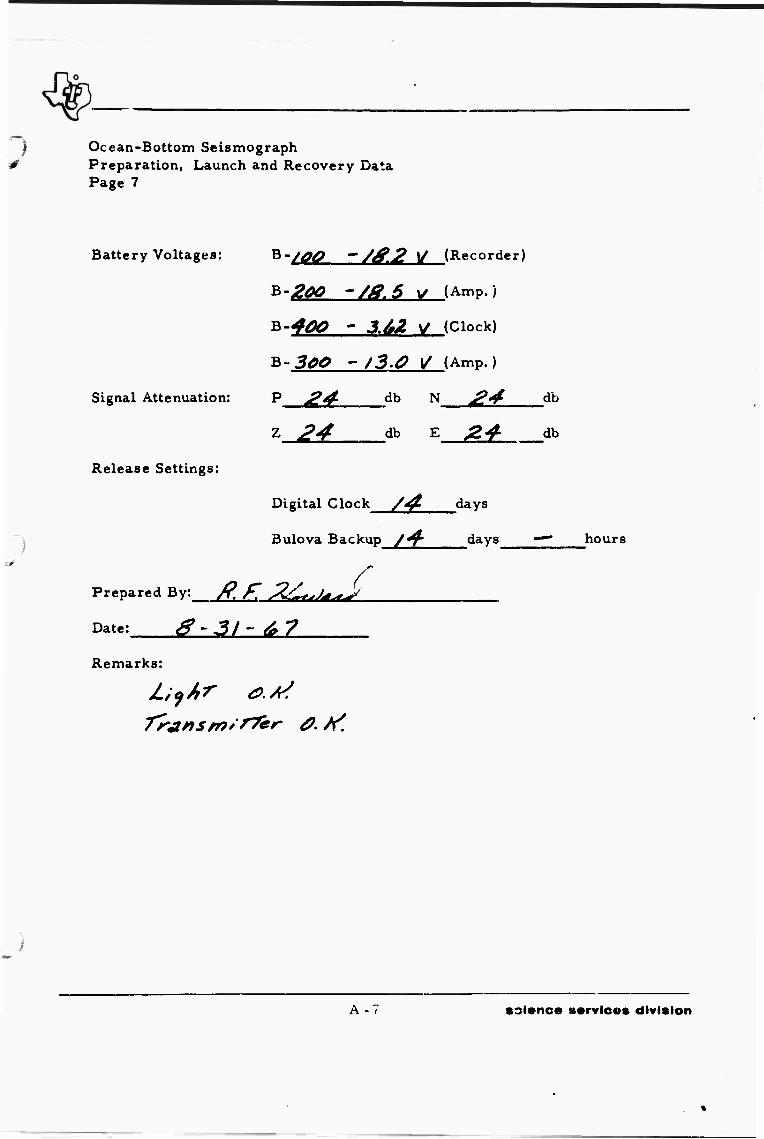
Ocean-Bottom Seismograph Preparation, Launch and Recovery Data Page 7
Battery Voltages:
Signal Attenuation: P £4"
Release Settings:
B-/^ ~/£2 \/ (Recorder)
*'200 -/ä.6 1/ (Amp. )
B-40O ~ 3.&Z V (Clock)
K-SOO ~ /3.0 V (Amp. )
db N ^4 db
db z 2* db ^L
Digital Clock /^ days
Bulova Backup /^ days """
Prepared By; /?. f, Z£,^^
Date: & ~ 31 - 6 7
Remarks:
hours
A -■ science s«rvic»s division

Ocean-Bottom Seismograph Preparation, Launch and Recovery Data Page 8
IV. RECOVERY DATA
Sphere No. JgJ Clock No. j£/ Position .5/
Time Soaar Recall Begins <& M„.
J£- Day
'* ' '0 GCT Hour Min.
Time Unit Determined on Surface 9 , JO , /9 . JZ2. Mo. Day Hour Min.
GCT
Determined By TrffiA/SArt/rTZ/?
Location
Latitude Wind -£ HK Longitude y?J?&47 '£ Barometer 30. &£
Determined Bv^yg^» £ faJar Weather ^/gj^ C^Jmf r**/
Unit Data
Time Unit Onboard Ship 9 Mo.
y^ ' -2* • O* GCT Day Hour Min.
Time Sphere Opened /^> 2.0 ?? GCT Day Hour Min.
Secondary Standard Error 0. Q at 9 , /& . 20 , _%& GCT Mo. Day Hour Min.
Secondary Standard No. /
Latch Relay Depressed JQ ^Q , 40 GCT Day Hour Min.
WWV Start _/£___, 26 ' -A$ ^1 Day Hour Min.
A-8 •ciane» ••rvic«s division

Ocean-Bottom Seismograph Preparation, Launch and Recovery Data Page 9
WWV Off 20 . £S GCT Hour Min.
Amp. Off 2a Ä& GCT Clock Off 20 , £7 GCT Hour Min. . Hour Min.
fctmrST off 20 S0 Tape Marked: ^ ^ . _£2_. 2.J . ^/
Day of Year Year Unit No. Clock No.
Battery Voltages:
B-100 /6.0 V (Rec. )
B-200 j£.& V (Amp. )
B-400 3.45 • (Clock)
B-300/^.^ •. (Amp. )
Prepared Bv: fff ^4(fa^
Date: 9 -/«O - 6 7 .
Remarks:
/./f/ff f TrainsmiT^er 0,^
CrooJ W\A/V S/'f/faJ
A -9/ 10 sclenc« services division

APPENDIX B
SAFETY REGULATIONS FOR HANDLING EXPLOSIVES
€
science services division

1 APPENDIX B
SAFETY REGULATIONS FOR HANDLING EXPLOSIVES
The following regulations are safety procedures which are in
effect during the loading, storage, preparation and launch, and detonation of
explosives during Ocean-Bottom Seismograph, operations. Responsibility
for observance lies with the shooter and shooter's helper. Responsibility
for enforcement lies wi«-h the safety engineer, operations manager, and
captain.
Loading
&
Storage
Each type of explosive must be loaded or unloaded separately.
No smoking will be allowed during loading or unloading.
Only a minimum »umber of personnel will be allowed in the immediate area during loading or unloading.
All transmitting equipment will be turned off during loading or unloading.
Fire equipment including dock water hose must be laid out and ready for quick use.
Special care must be exercised in handling blasting caps and primers; only the shooter or helper will load, unload- or handle these items.
Large prepackaged charges will be loaded and moved only by an ex- perienced crane operator.
Explosives must be stored properly in magazines, allowing proper venti- lation and braced with supplied dun- nage material.
Magazines are to be used omy for ex- plosives and must be ker' ci^an of dust, packing mater4' ' ,tc.
B-l science services division

Preparation and Launch
Magazines must be kept locked at all times when not in use; the shooter, operations manager, and captain will be the only keyholders.
An accurate count of all expended ex- plosives will be kept by the shooter, and copies of th'S count will Lv^ sub- mitted to the operations manager and captain at the end of each day when explosive detonations occur.
A complete inventory of explosives aboard ship will be made at the dis- cretion of the operations manager.
Work vests will be worn by all person- nel assisting in preparation and launch operations.
The prepackaged charge will be secured to the fantail of the ship before priming operations begin. Charges will be moved only by an experienced crane operator.
Sufficient working space will be pro- vided on the back deck before priming opeiations begin.
Only a minimum number of personnel will be allowed in the immediate area during preparation and launch operations.
The crane hook will be attached to the A-frame before priming operations begin.
The shooter will request a sweep by t e ship's radar for any ships witnin the area and will request that all trans- mitters be secured if area is clear.
No explosive detonations will be attempted during electrical storms.
B-2 science services division

* \f * f
■4/ A check will be made by the safety en-
gineer to insure that all transmitting equipment has been secured before priming operations commence.
The shooter's helper or safety engineer vill assist the shooter in removing from the magazine pvimers, boosters, and necessary items required for the present charge.
Only static-resistant caps will be used during operations.
Ah blasting caps must be placed in the lead-lined safety box as soon as pos- sible after their removal from the magazine.
The shooter or shooter's helper are the only personnel allowed to place primers anc boosters in the main charge.
All safety switches must be .1 good working order and must be checked before the caps are attached to the firing line.
After continuity checks are completed, the blasting caps will be connected to the firing line. This connection will be made as soon as possible after the shortinp shunt is removed from the cap leads.
Placing of the blasting caps in the main charge constitutes a "committed-to-go" condition, and the charge must be launched as soon as arming is complete.
Detonation No safety switches or transmitting equipment will be operated until the ship is a safe distance from the charge.
IT \r*i ■r\; — . 7 ffort will be made to kee^ the charge directly behind the ship at deto- nation.
B-3 science services division

^
In the event of a misfire, the charge will be cut off the buoy. The charge will never be brought back onboard the vessel.
Firing line and shooting equipment will be thoroughly tested at the discretion of the shooter or operations manager after additional firing line has been added, after equipment has been re- paired or replaced, and after a mis- fire has occurred.
B-4 science services division
APPENDIX C
RECOMMENDATIONS FOR REQUIRED MAINTENANCE ON EQUIPMENT
science services division

BLANK PAGE
T TBT,.,,.,

APPENDIX C
RECOMMENDATIONS FOR REQUIRED MAINTENANCE ON EQUIPMENT
All equipment should be restored to first-class condition after
the completion of each major field experiment. General cleaning, replace-
ment of damaged parts, and continual upgrading of equipment cannot be over-
stressed, as the success of any field operation depends on the ability of each
piece of equipment to function properly.
Recommendations for required maintenance on equipment fol-
lowing the Aleutian Islands Experiment follow.
OCEAN-BOTTOM SEISMOGRAPHS
Unit 1 Replace amplifier system with RA-fe package and add necessary batteries and wiring for uniform systems; re- place springs; complete general re- pair of tape recorder
Unit 16 Replace corroded center ring and re- pair pressure transducer
Unit 20 Reanodize and paint upper Hemisphere
Unit Z2 Reanodize and paint center ring
Unit 24 Reanodize and paint center ring
Unit 25 Replace amplifier system with RA-6 package and add necessary batteries and wiring for uniform system; re- turn Bulova Acutron clock to factory for repair
General (includes Clean completely all units) _,, i , , ,
Thoroughly check each component
Replace all O-rings
Replace all bent turnbuckles and rings
C - 1 science services division

Replace all beacon-light b?ti.teries plus spares
Replace antenna springs
Plastic-coat cables on bales and other hardware
Replace any batteries dated 1966 or earlier
Obtain spare light, transducer, and amplifier to insure total capability of instruments
Build spare sonar test box
Sonar Transmitter
Sonar Transducer
AUXILIARY EQUIPMENT
For unit 1: replace underrated tran- sistors and rectifiers; for unit 2: clean
Repaint and check for broken or damaged crystals
Playback Tape Pec -der
Paper Chart Recorder
Galvo Amplifier (2 units)
Fathometer (2 units)
D-X Navigator {2 units)
Omega Navigation System
WWV Receiver (2 units)
OEC Loop
Electrical Blasters
Oscilloscope (4 units)
Function Generators
Rebuild selector-box switch assembly
Repair four galvanometers
C'ean
Return to factory for servicing
Return to factory for maintenance and calibration
Have factory representative clean and repair in Dallas; add common ground to elh. inate noise; obtain spare parts
Return to factory for maintenance and alignment
Clean; replace batteries
Clean
Clean and complete necessary main- tenance and calibration
Clean and perform calibration check
C-2 science services division

High-Frequency Generator
Strobotac
RF Dummy Load and Wattmeter
Volt Ohmmeter (5 units)
Hammarlund Receiver
KWM-2A System
Ampex Tape Recorder
Geotech Timing System (2 units)
Box Buoy (2)
Hand Tools (2 sets)
Clean and calibrate
Clean and calibrate
Clean
Return for repair and maintenance, calibration and cleaning
Clean, realign, and install 3-wire power plug to prevent "hot" chassis problem
Clean and check
Replace amplifier channels; obtain spare parts
For unit 1: replace frequency standard, obtain solid-state programmer, clean and check. For unit 2: replace fre- quency standard, clean and check
Replace
Clean and replace missing or unusable tools
C-3/4 science services division
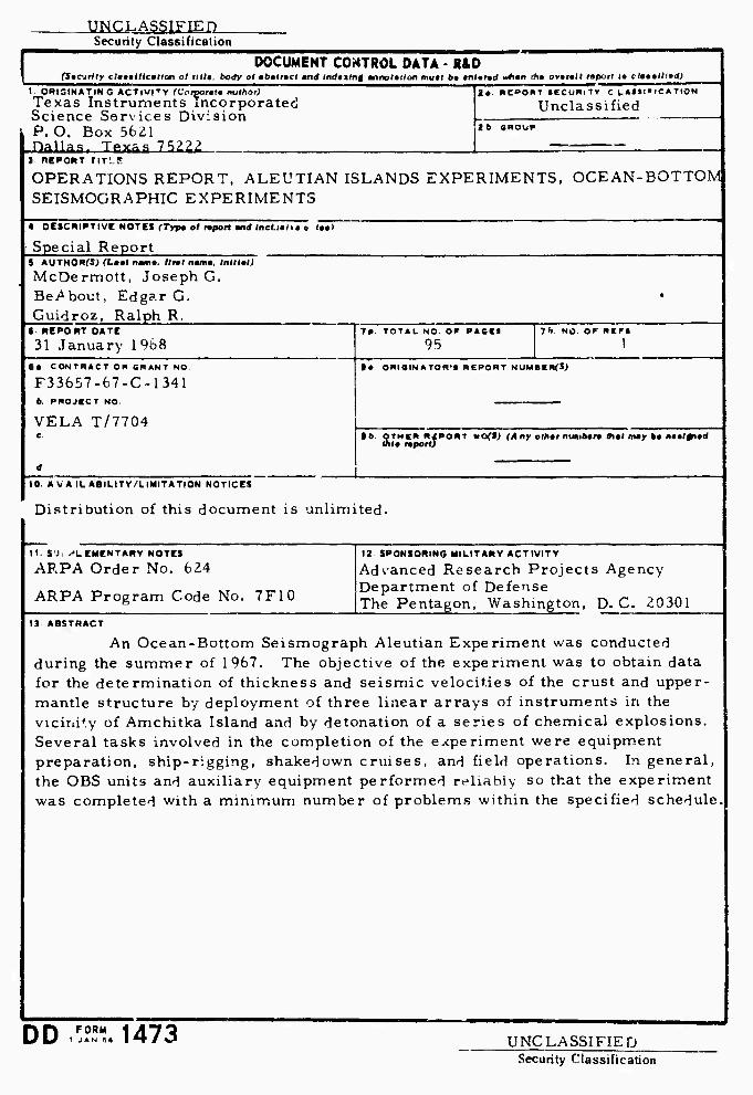
UNCLASSIFIED Security Classification
DOCUMENT CONTROL DATA • R&D (Sicjrlly cla»»llicmlHm of UM», body ol abstract and mdotmf annofa^on muaf ba anfarad whmn thm ovaratf tapotl it clmttlllid)
I ORifllNATIN G ACT(«ITY fCoiporata muthat) Texas Instruments incorporated Science Services Division P.O. Box 56Z1 Dallas. Texas 13112. .
Ja BEPOfIT ieCU«lTT C l.*t»l»ICATION
Unclassified tb GROUP
j KEPOUT riT'_!
OPERATIONS REPORT. ALEUTIAN ISLANDS EXPERIMENTS, OCEAN-BOTTOM SEISMOGRAPHIC EXPERIMENTS
4 DESCRIPTIVE NOTES (Typ* ol mpott and tnct.j.i.» «, taal
• Special Report S AUTHORCS; TLaat nama. ftnt nama, Inlllml)
McDermott, Joseph G. BeAbout, Edgar G. Guidroz, Ralph R.
6 REPORT DATE
31 January 1 968 ta CONTRACT OR ORANT NO.
F33657-67-C-1341 6. PROJCCT NO
VELA T/7704
7* TOTAL NO OP PAGES
95 7*>. NO OF RIP1
ta ORIOINATOR'I REPORT NUMBERf-Sj
»b OTHER N4PORT mo(t) (Any othtr nimiban tfiat may ba aaaianad ~ 0 tfifa raportj
10. A VA IU ABILITY/LIMITATION NOTICES
Distribution of this document is unlimited.
11. S'J. ELEMENTARY NOTES
ARPA Order No. 624
ARPA Program Code No. 7F10
12 SPONSORING MILITARY ACTIVITY
Advanced Research Projects Agency Department of Defense The Pentagon, Washington, D. C. 20301
13 ABSTRACT
An Ocean-Bottom Seismograph Aleutian Experiment was conducted during the summer of 1967. The objective of the experiment was to obtain data for the determination of thickness and seismic velocities of the crust and upper- mantle structure by deployment of three linear arrays of instruments in the vicini'.y of Amchitka Island and by detonation of a series of chemical explosions. Several tasks involved in the completion of the experiment were equipment preparation, ship-rigging, shakedown cruises, and field operations. In general, the OBS units and auxiliary equipment performed reliably so that the experiment was completed with a minimum number of problems within the specified schedule.
DD .FÄ 1473 UNCLASSIFIED Security Classification

UNCLASSIFIED Security Ciassification
KEY WORDS
Ocean-Bottom Seismograph
Aleutian Islands Experiment
Equipment Preparation
Ship-Rigging
Shakedown Cruise
Field Operations
Explosion Program
LINK A
INSTRUCTIONS
I. ORIGINATING ACTIVITY; Enter the nrnne and address of the contractor, subcontractor, grantee, Department of De- fense activity or other orgarization (cotporale author) issuing the report.
2a. REPORT SECUFITY CLASSIFICATION: Enter the over- all security classification of the report. Indicate whether "Restricted Data" is included. Marking is to be in accord- ance with appropriate security regulations.
2b. GROUP: Automatic dowagrading s specified in DoD Di- rective S200.10 and Armed Forces Iniustriat Manual. Enter the group number. Also, when applicable, show that optional markings hav«» been used for Group 3 and Group 4 as author- ized.
3. REPORT TITLE: Enter the complete report title in all capital letters. Titles in all cases should be unclassified. If a meaningful title cannot be selected without classifica- tion, show title classification in all capitals in parenthesis immediately following the title.
4. DESCRIPTIVE NOTES If appropriate, enter the type of report, e.g., interim, progress, summary, annual, or finnl. Give tlie inclusive dates when a specific reporting period is covered.
5. AUTHOR(S); Enter the jme(s) of authoKs) as shown on or in the report. Enlei last name, first name, middle initial. If xilitary. show rank pnd branch of service. The name of the principal a «thor is an absolute minimum requirement.
6. REPORT DAT!^ Enter the date of the report as day, month, year; or month, year. If more than one date appears on the report, use date of publication.
7a. TOTAL NUMBER OF PAGES: The total page count shou.'i follow normal pagination procedures, i.e., enter the number of pages containing information.
76. NUMUER OF REFERENCES: Enter the total number of references cued in the report.
8a CONTRACT OR GRANT NUMBER: M appropriate, enter the applicable number of the contract or grant under which »he repu.t was written.
8fc, 8r. & 8d. PROJECT NUMBER: Enter the appropriate military department identification, such as project number, »uhproject number, system numbers, task oumber, etc.
9a. ORIGiNATOK'J REPORT NUMBER(S): Enter the offi- cial report number b> which the document will be identifiad and controlled by the originating activity. This number mi.st be unique to this report.
06 OTHER REPORT NUMBER(S): If the report has been assigned uny other report nun.bers (eilhir hy the originator or by the sponsor), alf.c enter this number(s).
10. AVAILAPILITY/LIMITATION NOTICES: Enter any lim- itations on (urther dissemination of the report, other than those
imposed by security classification, using standard statements such as:
(1) "Qualified requesters may obtain copies of this report from DDC"
(2) "Foreign announcenunt and dissemination of this report by DDC is not authorized."
(3) "U. S. Government agencies may obtain copies of this report directly from DDC. Other qualified DDC users shall request through
(4) "U. 3. military agencies may obtain copies cf this report directly from DDC Other qualified users shall request through
(Si "All distribution of this report is controlled. Qual- ified DDC users shall request through
if 'he report has been furnished ti the Office of Technical Services, Department of Commerce, for sale to the public, indi- cate this fact and enter the price, if known.
U. SUPPLEMENTARY NOTES: Use for additional explana- tory notes.
li. SPONSORING MILITARY ACTIVITY: Enter the name of the departmental project office or laboratory sponsoring (pay- ing lor) the research and developmei.t. Include address.
13 ABSTRACT: Enter an abstrart giving a brief and factual summary of the document indicative of the teport. even though it m iy also appear elsewhere in the body of the technical re- port. If additional space is required, a continuation sheet shall be attached.
It is highly desirable that the abstract of classified reports be unclassified Each parn^raph of the ubstrai t sha!l end with an indication of the military security classification of the in- formation in the paragraph, represented as (T5). (S) (C). ..r (Ut
There is no Imitation en the length of the fhstrarl Ho* ever, the suggested length is from 1 SÜ to 225 words
14. KEYWORDS; Kc\ words are tei hmc ally meeninKful terms or short phrases that characterize a report and may be used us index entries for cataloKinK the report Key words must be selected so that no security classification is required Identi fiers, such as equipment model designation, trade name, military project codt name, geographK location, may be used as key- words but will he followed by an indication oi technical con- text. The assignment of links, rules, »nd weights is optional
ceo cgf. ssi UNCLASSIFIED Secuntv Classification