roadex network implementing accessibility
TRANSCRIPT

ROADEX Network Implementing Accessibility

ROADEX Network Implementing Accessibility
ROADEX road design method
ROADEX IV final seminarRovaniemi, 25 April 2012
Pauli KolisojaTampere University of Technology

ROADEX Network Implementing Accessibility
Outline of the presentation
• ROADEX definition of rutting modes• Principle of the design approach for Mode 1
rutting• Principle of the design approach for Mode 2
rutting• Determination of design parameters• Permanent deformation demonstrations sites
in Jämsä, Central Finland• Summary

ROADEX Network Implementing Accessibility
ROADEX definition of rutting modes
Mode 0 rutting
SoilAggregate
rut

ROADEX Network Implementing Accessibility
ROADEX definition of rutting modes
Mode 1 rutting
AggregateSoil
rut
ROADEX Network Implementing Accessibility
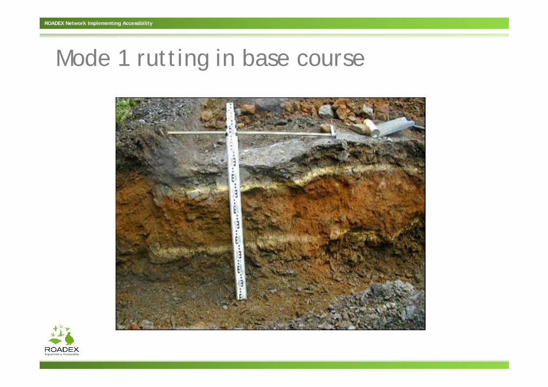
Mode 1 rutting in base course
ROADEX Network Implementing Accessibility
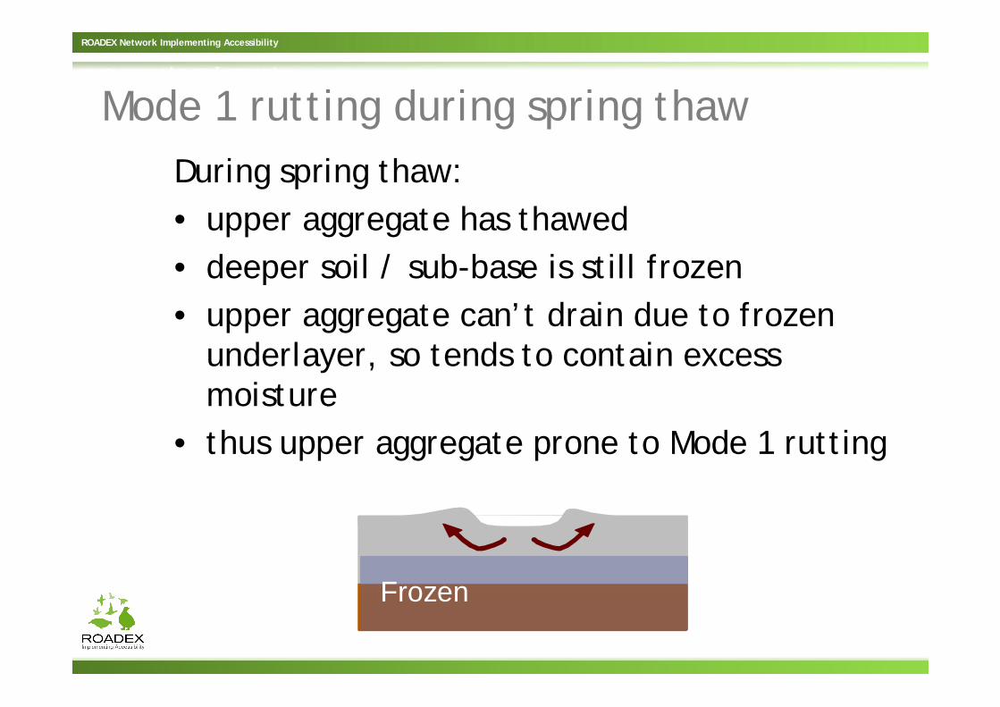
Mode 1 rutting during spring thawDuring spring thaw:• upper aggregate has thawed• deeper soil / sub-base is still frozen• upper aggregate can’t drain due to frozen
underlayer, so tends to contain excess moisture
• thus upper aggregate prone to Mode 1 rutting
Frozen

ROADEX Network Implementing Accessibility
ROADEX definition of rutting modes
Mode 2 rutting
Soil
Aggregate

ROADEX Network Implementing Accessibility
Severe mode 2 rutting in the subgrade

ROADEX Network Implementing Accessibility
Typical mode 2 rutting problem in the seasonal frost areas

ROADEX Network Implementing Accessibility
ROADEX definition of rutting modes
We can define three modes of rutting, depending on how and where the plastic strain accumulates
• Mode 0 = Compaction strain in upper layers• Mode 1 = Shear strains in the near-surface
layers• Mode 2 = Shear strains in deeper layers
(especially the subgrade)

ROADEX Network Implementing Accessibility
Basic solutions to Mode 1 rutting problem
• Ensure proper drainage • Improve quality/shear strength of the base
course material– Coarsen the base course - add course grained
aggregate and mixmil– Stabilize (using bituminous or hydraulic agents)– Use (hydrofobic) material treatment
• Reduce stresses in the existing base course– Add better quality material on top of in (AC or
unbound aggregate)– Use lower tyre inflation pressure (CTIS/TPCS)

ROADEX Network Implementing Accessibility
Basic solutions to Mode 2 rutting problem
• Ensure proper drainage • Reduce stresses in the subgrade by increasing
thickness of base/sub-base course layers• Improve quality/stiffness of the base course
material– Stabilize (using bituminous or hydraulic agents)– Coarsen the base course - add course grained
aggregate and mixmil – Use (hydrofobic) material treatment

ROADEX Network Implementing Accessibility
Load spreading achieved by thickness

ROADEX Network Implementing Accessibility
Load spreading achieved by higher stiffness aggregate

ROADEX Network Implementing Accessibility
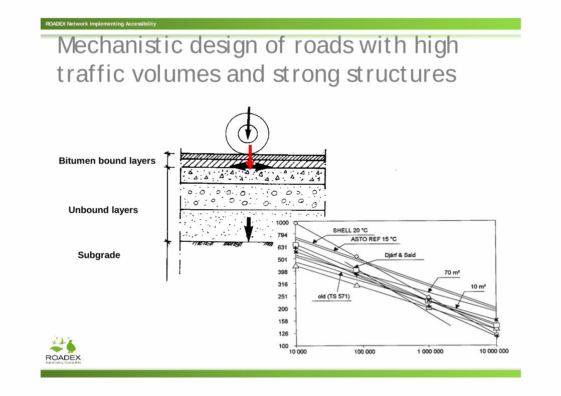
Mechanistic design of roads with high traffic volumes and strong structures
• At one load repetition stresses remain far from failure main distress mechanisms are fatigue of bound layers and/or slow/gradual rutting of unbound layers (or subgrade)
• Design is based on analysis of stresses and strains in critical points of the structure
• Required input parameters are stiffnesses of the layer materials and the subgrade
• Fatigue/deformation models are used to estimate the service life
ROADEX Network Implementing Accessibility
Bitumen bound layers
Unbound layers
Subgrade
Mechanistic design of roads with high traffic volumes and strong structures

ROADEX Network Implementing Accessibility
Mechanistic design of roads with low traffic volumes and weak structures
• At one load application stresses may approach close to failure severe distresses may develop even under very few load repetitions
• A ‘geotechnial approach’ is required to compare the load induced stresses and the ultimate load carrying capacity of the structure and/or subgrade
• In addition to stiffnesses the required input parameters include strength parameters of the structural layers and the subgrade

ROADEX Network Implementing Accessibility
ROADEX approach for Mode 1 rutting
• Aimed for roads with low traffic volumes / relatively thin stuctures
• Analysis is based on ‘geotechnical approach’ i.e. the wheel load induced stresses are compared to shear strength of the aggregate

ROADEX Network Implementing Accessibility
Variables included in Mode 1 design approach
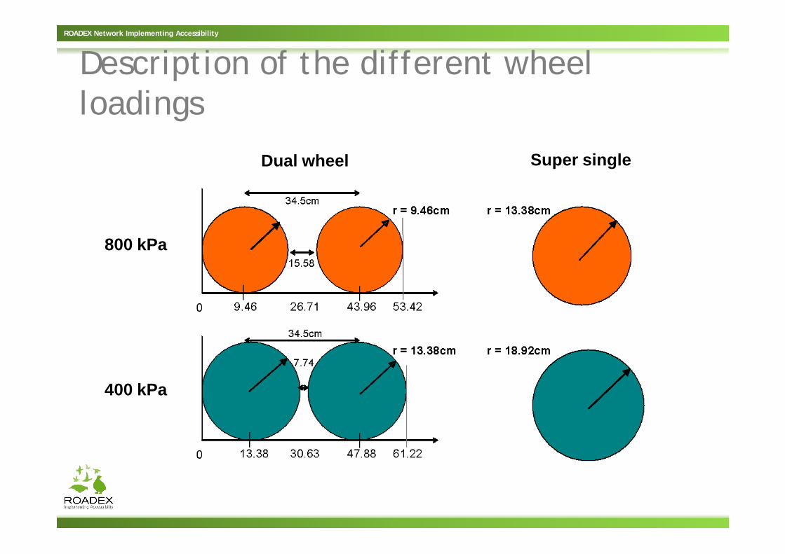
• Wheel configuration: dual wheel/super single• Tyre inflation pressure: 800 kPa/400 kPa• Thickness of the unbound layer (in relation to
the radius of loaded area under one tyre)• Aggregate stiffness/subgrade stiffness ratio • Mohr-Coulomb strength parameters (c and )
for the unbound (base course) aggregate
ROADEX Network Implementing Accessibility
Description of the different wheel loadings
Dual wheel Super single
800 kPa
400 kPa

ROADEX Network Implementing Accessibility
‘Proximity to failure’ approach

ROADEX Network Implementing Accessibility
Basic idea of Mode 1 rutting approach
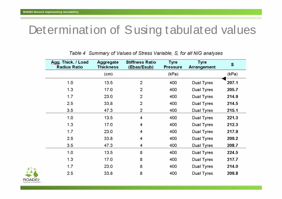
• An anaysis of stress quantities p and q (mean stress and deviator stress) corresponding to the actual loading case is made; in practise by using a set of graphs or tabulated values or a simple software tool
• ’Proximity to failure’ along the line between the points (p=250kPa, q=0) and (p=0, q=250kPa) is determined in terms of S/Sf ratio
• S/Sf ratio should not exceed 0,90 in dry conditions and 0,75 in wet conditions
ROADEX Network Implementing Accessibility
Determination of S using tabulated values

ROADEX Network Implementing Accessibility
Mode 1 design using a software toolto be available at: www.roadex.org

ROADEX Network Implementing Accessibility
Development of ROADEX approach for Mode 2 rutting – basic idea
• A ’geotechnical approach’ is aimed to be developed also for Mode 2 rutting
• Analysis of stress-strain distribution along the aggregate layers distribution of vertical stress on the subgrade surface level
• Estimation of the ultimate load carrying capacity of the subgrade is made by means of a geotechnical bearing capacity formula
• Sufficient factor of safety against failure of the subgrade is required

ROADEX Network Implementing Accessibility
Development of ROADEX approach for Mode 2 rutting – basic idea
Aggregate layers
Soft subgrade
Key questions are now:1. Stress distribution on the subgrade surface level2. Strength of the subgrade soil (and the aggregate layers)

ROADEX Network Implementing Accessibility
Calculation of stress distribution using the “1:2 approach”
Aggregate layer 0,4 m
Load 50 kNp = 800 kPar = 0,141 m
1
2 ?
psubgrade = 136 kPa

ROADEX Network Implementing Accessibility
Calculation of stress distribution using a multi-layer linear elastic software I
Aggregate layer 0,4 mE = 200 MPa
SubgradeE = 40 MPa
Load 50 kNp = 800 kPar = 0,141 m
Vertical stress under thecentre of loaded area 69 kPa
Tensile stress at the base ofaggregate layer 165 kPa !
ROADEX Network Implementing Accessibility
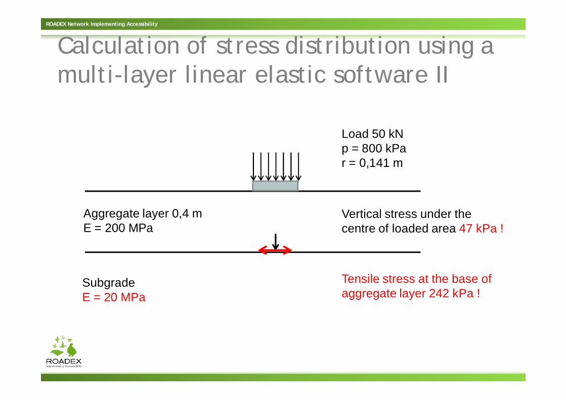
Calculation of stress distribution using a multi-layer linear elastic software II
Aggregate layer 0,4 mE = 200 MPa
SubgradeE = 20 MPa
Load 50 kNp = 800 kPar = 0,141 m
Vertical stress under thecentre of loaded area 47 kPa !
Tensile stress at the base ofaggregate layer 242 kPa !

ROADEX Network Implementing Accessibility
Calculation of stress distribution using a multi-layer linear elastic software III
Aggregate layer 0,4 mE = 200 MPa
SubgradeE = 10 MPa
Load 50 kNp = 800 kPar = 0,141 m
Vertical stress under thecentre of loaded area 31 kPa !
Tensile stress at the base ofaggregate layer 314 kPa !
ROADEX Network Implementing Accessibility
Development of ROADEX approach for Mode 2 rutting – a practical problem
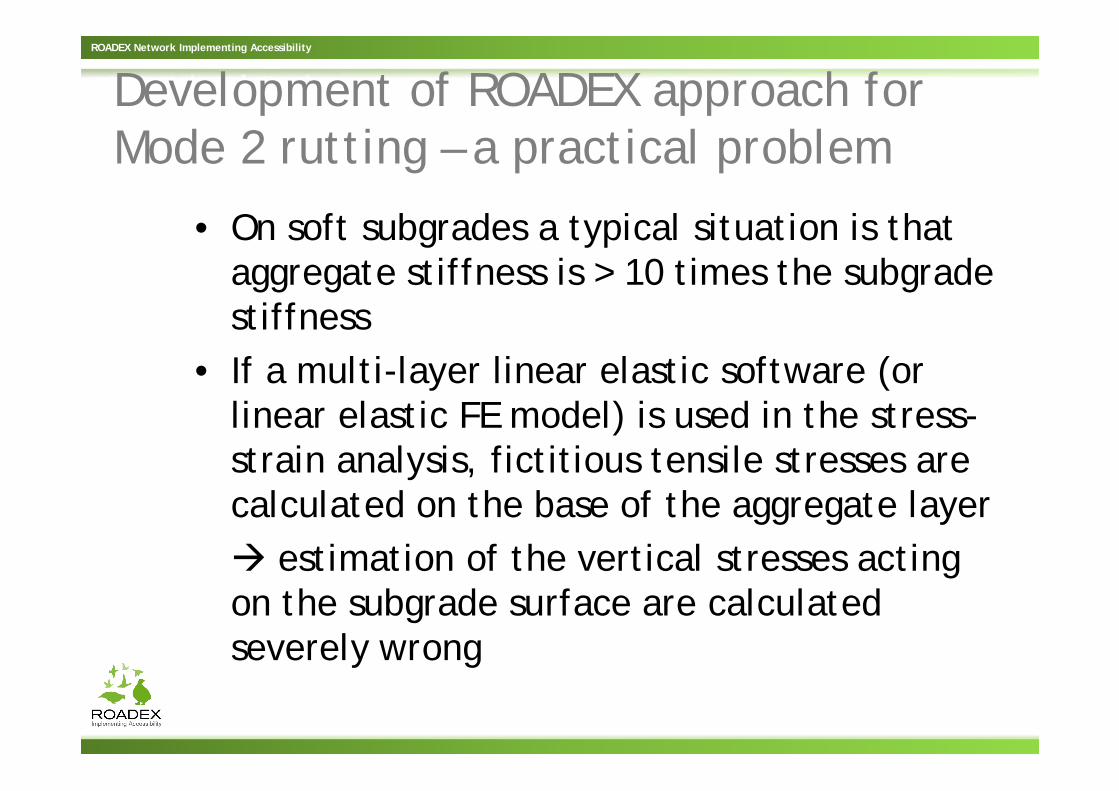
• On soft subgrades a typical situation is that aggregate stiffness is > 10 times the subgrade stiffness
• If a multi-layer linear elastic software (or linear elastic FE model) is used in the stress-strain analysis, fictitious tensile stresses are calculated on the base of the aggregate layer
estimation of the vertical stresses acting on the subgrade surface are calculated severely wrong

ROADEX Network Implementing Accessibility
PLAXIS-3D FE Moled of a single wheel
Structural layers 0,4 mE = 200 MPa
= 50 °c = 25 kPa
Subgrade 2,0 mE = 40 MPa
Load 50 kNp = 800 kPar = 0,141 m
Model area4 x 4 m2

ROADEX Network Implementing Accessibility
Vertical stress distribution on subgrade surface
Structural layers 0,4 mE = 200 MPa
= 50 °c = 20 kPa
Subgrade 2,0 mE = 40 MPa

ROADEX Network Implementing Accessibility
Vertical stress distribution in a cross section

ROADEX Network Implementing Accessibility
Vertical stress distribution on the subgrade surface in a cross section
?
?
ROADEX Network Implementing Accessibility
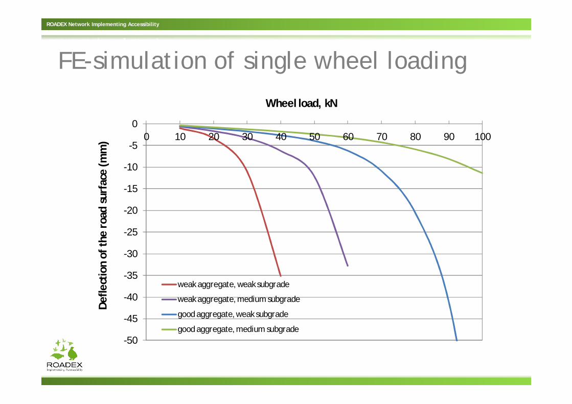
FE-simulation of single wheel loading
-50
-45
-40
-35
-30
-25
-20
-15
-10
-5
00 10 20 30 40 50 60 70 80 90 100
Def
lect
ion
of t
he r
oad
surf
ace
(mm
)Wheel load, kN
weak aggregate, weak subgrade
weak aggregate, medium subgrade
good aggregate, weak subgrade
good aggregate, medium subgrade

ROADEX Network Implementing Accessibility
Shear strain distribution: P = 40 kN,good aggregate, medium subgrade

ROADEX Network Implementing Accessibility
Shear strain distribution: P = 40 kN,good aggregate, weak subgrade

ROADEX Network Implementing Accessibility
Shear strain distribution: P = 40 kN,weak aggregate, medium subgrade
ROADEX Network Implementing Accessibility
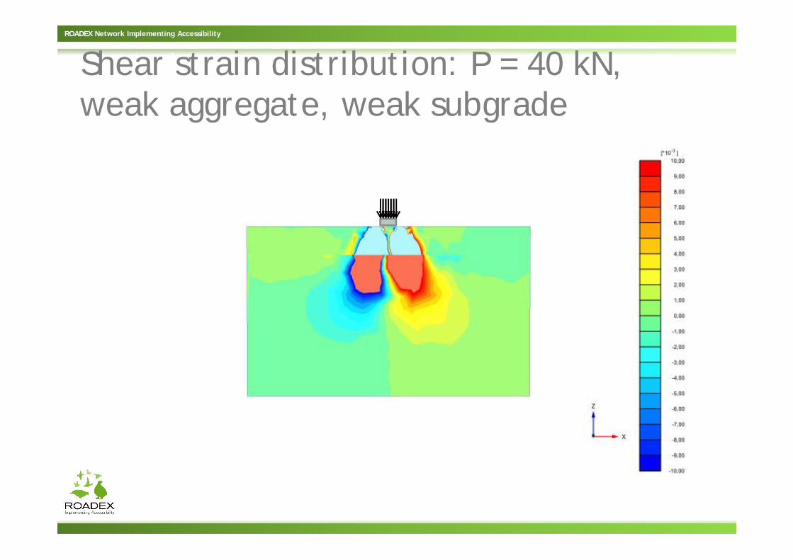
Shear strain distribution: P = 40 kN,weak aggregate, weak subgrade

ROADEX Network Implementing Accessibility
Variables that should be included into the FEM analysis
• Thickness of the aggregate layers• Aggregate material properties: shear strength
parameters (and stiffness)• Subgrade shear strength (and stiffness)• Wheel configuration; dual or single• (Tyre inflation pressure)

ROADEX Network Implementing Accessibility
Determination of a basic set of shear strength parameters for design against rutting
• Test variables– Material type/origin– Grain size distribution
(especially the fines content)
– Moisture content– Density
• The results are to be implemented into the software tool available at the ROADEX website

ROADEX Network Implementing Accessibility
An example of the multi-stage monotonous loading triaxial test results
Cell pressure130 kPa
70kPa
40kPa
20kPa

ROADEX Network Implementing Accessibility
Typical grain size distributions of the test materials
In addition to these basic grain size distributions fines content was variedand some of the test materials were made ’artificially’ by mixing wearingcourse material from an existing road with the Finnish aggregate.

ROADEX Network Implementing Accessibility
Suggested values for strength parameters Material quality Moisture content Compaction level Cohesion* Phi ( )
Good Normal OK / Appropriate 25 50
Good Normal Not Ok / Inappropriate 25 37.5
Good High OK / Appropriate 10 50
Good High Not Ok / Inappropriate 10 37.5
Medium Normal OK / Appropriate 10 45
Medium Normal Not Ok / Inappropriate 10 30
Medium High OK / Appropriate 5 45
Medium High Not Ok / Inappropriate 5 30
Poor Normal OK / Appropriate 10 40
Poor Normal Not Ok / Inappropriate 10 22.5
Poor High OK / Appropriate 0 40
Poor High Not Ok / Inappropriate 0 22.5

ROADEX Network Implementing Accessibility
Criteria for good quality material
• Tube Suction (TS) test result Er < 9, and• Fines content < 5% ,and• Material does not contain mica or other
weathering minerals.
Additional criteria that can also be considered include:
• Specific surface area of fines < 3000 m2/kg• Water adsorption index < 2

ROADEX Network Implementing Accessibility
Tube Suction (TS) test

ROADEX Network Implementing Accessibility
Criteria for medium quality material
• TS-test result 9 < Er < 16, and• Fines content < 12 %• If material contains high amount of mica or
other poor quality weathering minerals, fines content < 7 %

ROADEX Network Implementing Accessibility
Criteria for poor quality material
• TS-test result Er > 16, or• Fines content > 12 %. If the material contains
a high amount of mica or other poor quality weathering minerals, fines content > 7 %

ROADEX Network Implementing Accessibility
Dynamic Cone Penetration (DCP) test

ROADEX Network Implementing Accessibility
Leightweight FWD / Dynamic PBT

ROADEX Network Implementing Accessibility
Ehikki-Juokslahti I, reducing permanent deformations by improving drainage

ROADEX Network Implementing Accessibility
Ehikki-Juokslahti I, reducing permanent deformations by improving drainage
Spring time bearing capacity loss and permanent deformation site due to‘disappearing ditch’ in a silty moraine slope.

ROADEX Network Implementing Accessibility
Ehikki-Juokslahti I, reducing permanent deformations by improving drainage
‘Standard ROADEX solution’ to make a long lasting drainage improvementin a condition were the available space is not a limitation.

ROADEX Network Implementing Accessibility
Ehikki-Juokslahti I, reducing permanent deformations by improving drainage

ROADEX Network Implementing Accessibility
Ehikki-Juokslahti I, drainage improvement structure after the first winter

ROADEX Network Implementing Accessibility
Ehikki-Juokslahti I, drainage improvement ‘reference’ structure before cleaning the ditch in 2010 and after the first spring thaw in 2011

ROADEX Network Implementing Accessibility
Ehikki-Juokslahti II, reducing permanent deformations by improving drainage

ROADEX Network Implementing Accessibility
Ehikki-Juokslahti II, reducing permanent deformations by improving drainage
Severe spring time bearing capacity loss and permanent deformation site due to side sloping ground surface – available road area very limited.

ROADEX Network Implementing Accessibility
Ehikki-Juokslahti II, reducing permanent deformations by improving drainage
‘Adjusted ROADEX solution’ to make a long lasting drainage improvementin a sloped ground surface were the available space is a strict limitation.

ROADEX Network Implementing Accessibility
Ehikki-Juokslahti II, reducing permanent deformations by improving drainage

ROADEX Network Implementing Accessibility
Ehikki-Juokslahti II, reducing permanent deformations by improving drainage

ROADEX Network Implementing Accessibility
Ehikki-Juokslahti II, reducing permanent deformations by improving drainage

ROADEX Network Implementing Accessibility
Ehikki-Juokslahti II, drainage improvement structure after the first winter

ROADEX Network Implementing Accessibility
Ehikki-Juokslahti II, drainage improvement ‘reference’ structure

ROADEX Network Implementing Accessibility
Ehikki-Juokslahti III, reinforcement of a Mode II rutting site on peat subgrade

ROADEX Network Implementing Accessibility
Ehikki-Juokslahti III, reinforcement of a Mode II rutting site on peat subgrade
Mode II rutting and related widening of the road cross section on a peat area - poor drainage due to inoperative outlet ditch.

ROADEX Network Implementing Accessibility
Ehikki-Juokslahti III, reinforcement of a Mode II rutting site on peat subgrade

ROADEX Network Implementing Accessibility
Ehikki-Juokslahti III, reinforcement of a Mode II rutting site on peat subgrade

ROADEX Network Implementing Accessibility
Ehikki-Juokslahti III, reinforcement of a Mode II rutting site on peat subgrade

ROADEX Network Implementing Accessibility
Ehikki-Juokslahti III, Mode II rutting site after the first winter

ROADEX Network Implementing Accessibility
Saalahti, reinforcement of a Mode II rutting site on a silty subgrade

ROADEX Network Implementing Accessibility
Saalahti, reinforcement of a Mode II rutting site on a silty subgrade
Mode II rutting and related extensive widening of the road cross section on a silty subgrade area - side ditches have practically disappeared.

ROADEX Network Implementing Accessibility
Saalahti, reinforcement of a Mode II rutting site on a silty subgrade

ROADEX Network Implementing Accessibility
Saalahti, reinforcement of a Mode II rutting site on a silty subgrade

ROADEX Network Implementing Accessibility
Saalahti, reinforcement of a Mode II rutting site after the first winter

ROADEX Network Implementing Accessibility
Saalahti, typical drainage problems of the area one year after ditch cleaning

ROADEX Network Implementing Accessibility
Summary of the permanent deformation demonstration sites in Jämsä area
• All of the test structures were observed to be in very good condition after the first winter period
• Settlement tubes didn’t indicate any marked deformations in the cross sections so far
• Reports on all of the four test sites now available at: www.roadex.org
• Next monitoring cycle of the sites in spring/early summer 2012 concise revising of the reports if required

ROADEX Network Implementing Accessibility
Summary of the presentation• New mechanistic design approach for Low
Volume Roads has been developed• In low budget projects determination of the
input parameters for the mechanistic design remains a challenge
• After all, everything is based on correct problem analysis/diagnosis, sound understanding of the distress mechanisms and fit-for-purpose rehabilitation solutions
• Finally, remember always to keep drainage operative

ROADEX Network Implementing Accessibility
Questions ?

ROADEX Network Implementing Accessibility