robocup rescue 2014 - robot league team … · taller de robotica, facultad de ingenieria,...
TRANSCRIPT

RoboCup Rescue 2014 - Robot League TeamUNAM.ORG (Mexico)
David Angeles, Gabriel Arroyo, Jakob Culebro, Jose Luis Espinoza, HumbertoGutierrez, Manuel Lara, Yukihiro Minami, Stalin Muñoz, Gerardo Ramos
Taller de Robotica, Facultad de Ingenieria, Universidad Nacional Autonoma de Mexico(UNAM)
Av. Universidad 3000, Coyoacan, D. F., Mexico, C. P. [email protected],[email protected], [email protected]
tel. 52 55 5622 8199
http://dcb.fi-c.unam.mx/TallerRobotica
Abstract. This paper describes the work performed by the UNAM.ORG teamwith the goal of creating a search and rescue robot, able to assist rescuebrigades in tasks such as the exploration of semi-collapsed buildings and thesearch for survivors in disaster environments. Our team has been developingthis project for two years now. During this time we have acquired valuableexperience to approach the search and rescue tasks required at this competition.As part of the developing process, we crafted three different prototypes of ourrobot, each time having better locomotion or manipulation capabilities. In thispaper we mainly focus on describing each of the systems of our most recentprototype, called FinDER v2. This last version was designed with the goal inmind of participating in the RoboCup 2014 in Brazil, and, by doing so, ofhaving the opportunity of extensively testing the design in a challenging arena,as well as receiving critical feedback from the search and rescue roboticscommunity.
Introduction
The UNAM.ORG team was formed in October of 2011 with the goal ofresearching within the field of search and rescue robotics by building a prototype thatcould help rescue brigades in search and rescue deployments. Mexico City isespecially vulnerable to earthquakes strikes due to its geographical location near theNorth American, Cocos, and Pacific plates. Moreover, because it was built on a lake,land is soft and susceptible to displacements and building sinking. As a consequencethere is an increasing interest in developing technology that may be of help to reducehuman casualties in the aftermath of this kind of disasters.

Our team has mainly develop ground rescue robots, focusing on navigation andmanipulation tasks, for which we have acquired important experience. In a more earlystage of development, we have built a prototype for an unmanned aerial vehicle, andare currently at the design phase of an unmanned underwater vehicle, and a swarm ofsmall-size search and rescue explorers.
Our ground rescue robot is called FinDER (Finder in Disaster EnvironmentRobot), and has two previous versions. FinDER v1 was the first prototype. It was amobile robot with a small robotic arm on it. This robot had four wheels, two of themomnidirectional wheels, to provide differential motion. The robot FinDER v1 isshown in Fig. 1. Navigation and sensor fusion was successful, but we had someproblems with the main motors that overheated frequently and eventually failed. As aconsequence, we had to move to another solution to address the mobility problem.Also, the robotic arm we used was a commercial servo actuated system, and themaximum reach was very limited for the required functionality.
Fig. 1 FinDER v1 prototype.
The second approach to our rescue robot was to adapt a previously built mobileplatform to which a manipulator was attached. The new robotic arm was designedfrom scratch. It has 5 DoF and can reach things up to 1 meter away from its base. Thename of this prototype was FinDER v0. Although the new robotic arm significantlyimproved the manipulation capabilities as compared to v1, the robot could only moveon plain surfaces, lacking the mobility required in disaster environments.Nevertheless, v0 prove very useful at testing navigation, sensor fusion andmanipulation. An image of FinDER v0 is shown in Fig. 2.
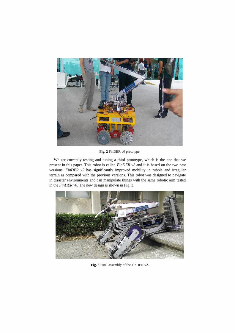
Fig. 2 FinDER v0 prototype.
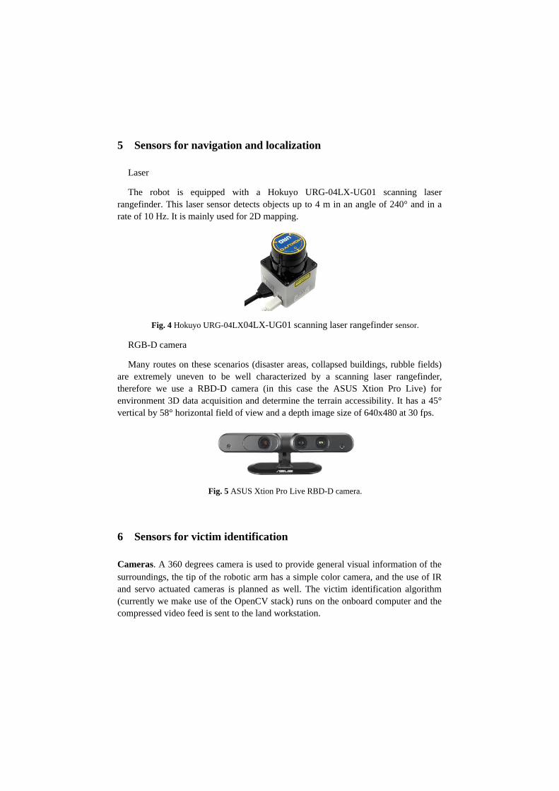
We are currently testing and tuning a third prototype, which is the one that wepresent in this paper. This robot is called FinDER v2 and it is based on the two pastversions. FinDER v2 has significantly improved mobility in rubble and irregularterrain as compared with the previous versions. This robot was designed to navigatein disaster environments and can manipulate things with the same robotic arm testedin the FinDER v0. The new design is shown in Fig. 3.
Fig. 3 Final assembly of the FinDER v2.

The FinDER v2 robot has an on board commercial laptop computer and is operatedremotely by another workstation. It has a 5 DOF robotic arm and some cameras forvictim detection and for remote navigation purposes. It is a differential robot, with acaterpillar drive system. It has four flipper arms to help the robot to climb littleobstacles and help in navigation tasks. Also has temperature and gas sensors to detectpotential victims and dangerous places for rescue teams.
1 Team members and their contributions
• Alejandro Pimentel Robotic arm set-up• Angeles Rodriguez Mechanical design• David Angeles Electronic design• Jakob Culebro Programming and electronic design• Jose Luis Espinosa Promotional material designer• Gabriel Arroyo SLAM programming and robotic arm design• Gabriel Perez Motor drivers set-up• Gerardo Ramos Mechanical design• Humberto Gutierrez Sensors set-up• Kevin Arias Robotic arm set-up• Manuel Lara User interface programmer• Mijail Avila Robotic arm set-up • Raul Peralta Computer vision• Stalin Munoz Artificial Intelligence advisor• Yukihiro Minami Faculty advisor
1 Operator station set-up and break-down (10 minutes)
The operator station consist of a laptop connected to one joystick for controllingthe robot navigation and the robotic arm. The laptop is connected to a router placed inthe operator station, all these are fitted in a backpack carried by the operator. Therobot has to be transported by two persons from the worktables to the start point in thearena using handlers in the robot.

2 Communications
Our communication system uses a wireless LAN, we connect the robot’s onboardcomputer with the operator's workstation using a router, enabling remote operationthrough ROS. An XBee Pro Series 1 pair is also enabled as a limited bandwidth linkof last resort, in case of onboard computer failure. This may enable very simpleteleoperation. The communication chart is shown in the Table 1. All microcontrollersare connected to the onboard computer in a master/slave architecture using the serialprotocol and ROS.
Table 1 Communications chart.
Rescue Robot League
UNAM.ORG (Mexico)
Frequency Channel/Band Power (mW)
5.0 GHz - 802.11a/n 149, 153, 157, 161 500
2.4 GHz - 802.11b/g Any 500
2.4 Ghz - 802.15.4 12 - 23 60
3 Control method and human-robot interface
The FinDER v2 robot is operated remotely, either by a single operator using astandard Xbox 360 game controller, or if desired, with additional modes of operation,it allows for the use of a pair of controllers.
The onboard computer performs most of the heavy lifting and higher controloperations. Each motor is controlled in position or speed (the differential tractionmotors are the only ones controlled in this way) using a simple PID loop implementedin AVR microcontrollers, reading the shaft angular position with 10 bit Hall effectabsolute encoders. In case of a timeout event, the microcontrollers are programmed toshut down the motors until further control signals are received.
The motors themselves are driven using OSMC (Open Source Motor Controllers) forthe differential traction motors, and Talon Anti-phase locked bridges for the smallermotors. A custom MOSFET H bridge was developed to control the small arm motors.

The interface used for testing is deployed on the operator's workstation. Allcommunications with the robot computer are performed through the ROScommunication stack. The different modules of the robot are connected to theonboard computer, where the ROS core server resides. Basic information of the stateof the robot can be seamlessly retrieved with ROS. An alternate web version isplanned in the near future.
A couple of camera views can be displayed remotely individually or using the ROSGUI packages. The arm camera feed shows victim identification marks as greenrectangles.
For rapid interface deployment, the onboard computer runs a roscore daemon loadedat startup. Both computers are SSH and Remote Desktop enabled, and use anautomated tiling window manager to distribute workspaces and assign windowpositions with minimal hassle.
4 Map generation/printing
The map generation is based on the well-known hector_slam package. It uses a 2Dgrid-based Simultaneous Localization and Mapping (SLAM) algorithm. The mapconstruction is developed from depth data by a scan matching approach. The mainsensor for solving the SLAM problem is an ASUS Xtion PRO which is a RGB-Dcamera capable of reconstructing a 3D representation of the environment.Modifications have been made on the algorithm to enable the use of such sensor.Although the map is drawn in 2D, a 3D sensing is made to let the robot know a betterapproximation of its environment and calculate the most accessible and secure path tothe victims. This information is transformed into relevant 2D data used to draw themap and navigate. This approach, however, is slow, having an update rate of less than5 Hz. Therefore a laser sensor is also used, on less rough terrain, to duplicate this ratecausing an increment in the velocity of the map construction and allowing the robot tomove faster.
5 Sensors for navigation and localization
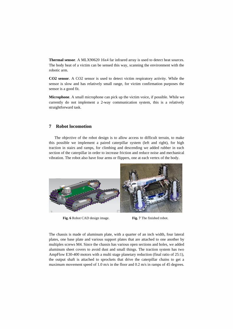
Laser
The robot is equipped with a Hokuyo URG-04LX-UG01 scanning laserrangefinder. This laser sensor detects objects up to 4 m in an angle of 240° and in arate of 10 Hz. It is mainly used for 2D mapping.
Fig. 4 Hokuyo URG-04LX04LX-UG01 scanning laser rangefinder sensor.
RGB-D camera
Many routes on these scenarios (disaster areas, collapsed buildings, rubble fields)are extremely uneven to be well characterized by a scanning laser rangefinder,therefore we use a RBD-D camera (in this case the ASUS Xtion Pro Live) forenvironment 3D data acquisition and determine the terrain accessibility. It has a 45°vertical by 58° horizontal field of view and a depth image size of 640x480 at 30 fps.
Fig. 5 ASUS Xtion Pro Live RBD-D camera.
6 Sensors for victim identification
Cameras. A 360 degrees camera is used to provide general visual information of thesurroundings, the tip of the robotic arm has a simple color camera, and the use of IRand servo actuated cameras is planned as well. The victim identification algorithm(currently we make use of the OpenCV stack) runs on the onboard computer and thecompressed video feed is sent to the land workstation.
Thermal sensor. A MLX90620 16x4 far infrared array is used to detect heat sources.The body heat of a victim can be sensed this way, scanning the environment with therobotic arm.
CO2 sensor. A CO2 sensor is used to detect victim respiratory activity. While thesensor is slow and has relatively small range, for victim confirmation purposes thesensor is a good fit.
Microphone. A small microphone can pick up the victim voice, if possible. While wecurrently do not implement a 2-way communication system, this is a relativelystraightforward task.
7 Robot locomotion
The objective of the robot design is to allow access to difficult terrain, to makethis possible we implement a paired caterpillar system (left and right), for hightraction in stairs and ramps, for climbing and descending we added rubber in eachsection of the caterpillar in order to increase friction and reduce noise and mechanicalvibration. The robot also have four arms or flippers, one at each vertex of the body.
Fig. 6 Robot CAD design image. Fig. 7 The finished robot.
The chassis is made of aluminum plate, with a quarter of an inch width, four lateralplates, one base plate and various support plates that are attached to one another bymultiples screws M4. Since the chassis has various open sections and holes, we addedaluminum sheet covers to avoid dust and small things. The traction system has twoAmpFlow E30-400 motors with a multi stage planetary reduction (final ratio of 25:1),the output shaft is attached to sprockets that drive the caterpillar chains to get amaximum movement speed of 1.0 m/s in the floor and 0.2 m/s in ramps of 45 degrees.

Fig. 8 CAD views of the robot.
The robot has four articulate arms of traction (flippers), each one driven by a DC gearmotor (AndyMark PG71) joined to #25 chains and sprockets that drive them; eacharticulate arm measures 30 cm, and can be used to avoid obstacles like stairs, tubes,etc.
Fig. 9 Close view of the flippers.

8 Other mechanisms
Robotic arm
The function of the onboard robotic arm allows the mobile robot to obtain thermaland acoustic signals from high zones or hidden from direct vision, easing thedetection of victims. The arm is anthropomorphic with three rotational joints in thetrunk, shoulder and elbow, and a “hand” with two degrees of freedom. The frame ofthe arm consists of aluminium sheets bended in a “U” form. To reduce load on thearm structure, the DC gear motors AndyMark PG188 are in the trunk and joined tothe links with timing belts and pulleys. The trunk itself is moved with a worm-gearmotor assembly with a 30:1 ratio and spins at 60°/second, and is attached to the robotthrough a cylinder with bearings that lets it turn. For moving the hand we use a servoFutaba S3305 with metallic gears. In the end of the arm we put a gripper, modelCrustCrawler Big Grip with an AX-12 digital Servo.
Fig. 10 Arm CAD design image. Fig. 11 The finished arm.

9 Team training for operation (human factors)
We aimed at making an intuitive interface, this objective is due to the robot having12 degrees of freedom and as such is hard to manipulate. So the interface is controlledby an Xbox 360 wired control, and we use a button to select a section of robot tomanipulate (enabling “modes”), also in the interface we have multiple camera feedsof the robot to view the movement robot over the arena.
10 Possibility for practical application to real disaster site
The robot was designed considering the practical applications in a disaster site.Several meetings and interviews have taken place with search and rescue profesionalpractitioners with ample experience in natural and man made catastrophes. Theircomments and suggestions have been taken into account, in an increasing mannerwith each new version of our robot. At the moment FinDER v2 is robust enough tomove without any problem through a simulated rough terrain in a controlledlaboratory. Right now the most critical points are the environmental factors, like dustand humidity, other factors like fire and smoke would also be a problem. More workhas to be done before conducting test missions in real rubble or disaster terrain.
11 System cost
The cost are in USD.
Mechanical
Items Quantity CostChassis (plate, sprocket, chains and manufacturing) 1 $ 2,500.00
AmpFlow E30-400 Motor 2 $ 218.00
PG71-AM9015 AndyMark motor 4 $ 356.00
Gearbox am-0401 AndyMark 2 $ 326.00
AX-12 Robot gripper 1 $ 99.00
Robotic arm frame 1 $ 1,000.00
PG188-RS775 AndyMark motor 2 $ 158.00
Timing belts and pulleys $ 100.00
5 W motor 1 $ 15.00
Other small components 1 $ 100.00
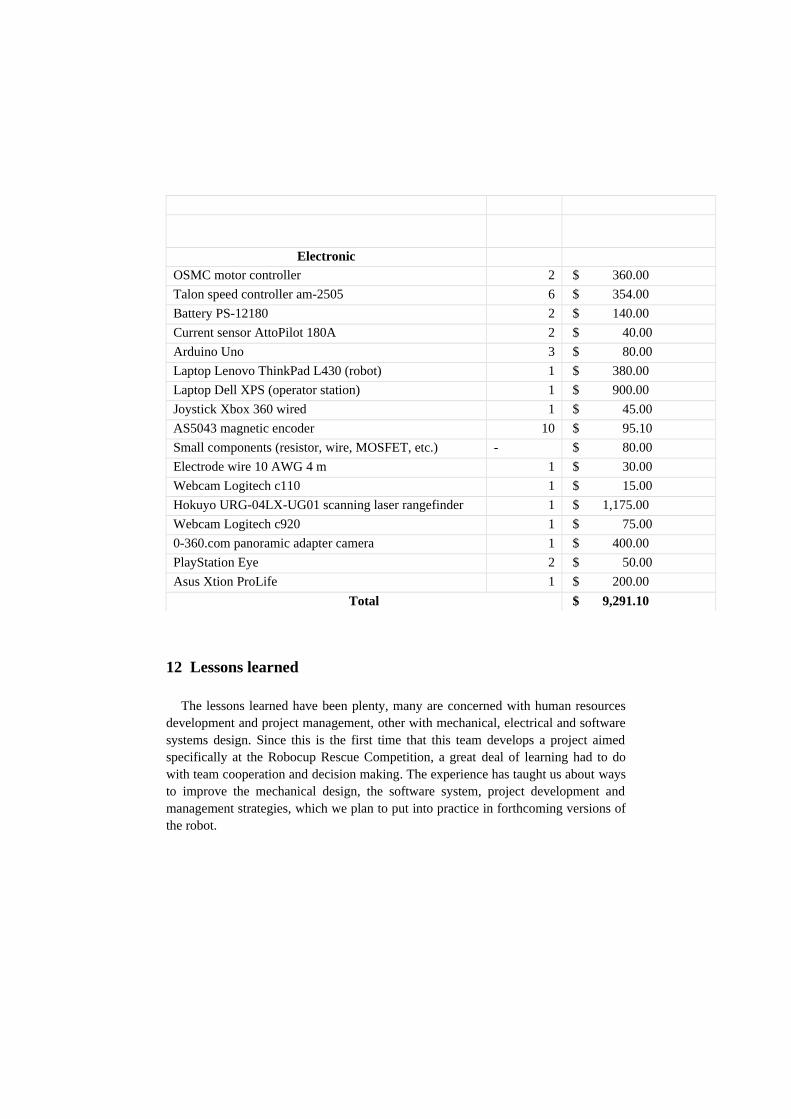
ElectronicOSMC motor controller 2 $ 360.00
Talon speed controller am-2505 6 $ 354.00
Battery PS-12180 2 $ 140.00
Current sensor AttoPilot 180A 2 $ 40.00
Arduino Uno 3 $ 80.00
Laptop Lenovo ThinkPad L430 (robot) 1 $ 380.00
Laptop Dell XPS (operator station) 1 $ 900.00
Joystick Xbox 360 wired 1 $ 45.00
AS5043 magnetic encoder 10 $ 95.10
Small components (resistor, wire, MOSFET, etc.) - $ 80.00
Electrode wire 10 AWG 4 m 1 $ 30.00
Webcam Logitech c110 1 $ 15.00
Hokuyo URG-04LX-UG01 scanning laser rangefinder 1 $ 1,175.00
Webcam Logitech c920 1 $ 75.00
0-360.com panoramic adapter camera 1 $ 400.00
PlayStation Eye 2 $ 50.00
Asus Xtion ProLife 1 $ 200.00
Total $ 9,291.10
12 Lessons learned
The lessons learned have been plenty, many are concerned with human resourcesdevelopment and project management, other with mechanical, electrical and softwaresystems design. Since this is the first time that this team develops a project aimedspecifically at the Robocup Rescue Competition, a great deal of learning had to dowith team cooperation and decision making. The experience has taught us about waysto improve the mechanical design, the software system, project development andmanagement strategies, which we plan to put into practice in forthcoming versions ofthe robot.
References
1. V. M. Faires, Diseño de elementos de máquinas, Montaner y Simón, Barcelona, Spain,1977.
2. Joseph Shigley, Richard G. Budymas, J. Keith Nisbett, Diseño en ingeniería mecánica,McGraw Hill, 9a edición, Mexico, 2012.
3. Willow Garage. Documentation ROS wiki. http://www.ros.org/wiki/, October 2013.
4. O´Kane Jason M. A Gentle Introduction to ROS. October 2013.
5. Andreas Nüchter, Kai Lingemann, Joachim Hertzberg, Oliver Wulf, Bernardo Wagner,Kai Pervölz, Hartmut Surmann, and Thomas Christaller. The robocup rescue teamdeutschland1, 2009.
6. J. Suthakorn, S. S. H. Shah, S. Jantarajit, W. Onprasert, W. Saensupo, S. Saeung, S.Nakdhamabhorn, V. Sa-Ing, and S. Reaungamornrat. On the design and development of arough terrain robot for rescue missions. In Proceedings of the 2008 IEEE InternationalConference on Robotics and Biomimetics, 2009.
7. S. Ali. A. Moosavian, S. Hesam, A. Kalantari, Design and Manufacturing of a MobileRescue Robot. In the proceedings of 2006 IEEE/RSJ International Conference onIntelligent Robots and Systems.
8. Navneet Dalal and Bill Triggs. Histograms of oriented gradients for human detection. InCordelia Schmid, Stefano Soatto, and Carlo Tomasi, editors, International Conference onComputer Vision & Pattern Recognition, volume 2, pages 886–893, INRIA Rhône-Alpes,ZIRST-655, av. de l’Europe, Montbonnot-38334, June 2005.
9. Kohlbrecher S, von Stryk O, Meyer J, and Klingauf U. A flexible and scalable SLAMsystem with full 3d motion estimation. IEEE, 2011
10. Keiji Nagatani, Hiroshi Ishida, Satoshi Yamanaja y Yukata Tamaka. Three-dimensionalLocalization and Mapping for Mobile Robot in Disaster Environments. InternationalConference on Intelligent Robots and Systems, Las Vegas, Nevada, October 2003.
11. Peter Zhang, Evangelous Millos y Jason Gu. General Concept of 3D SLAM. DalhousieUniversity, Canada. 2008. Leonard, John, and P. Newman. Consistent, convergent, andconstant-time SLAM. International Joint Conference on Artificial Intelligence. Vol. 18.Lawrence Erlbaum Associates Ltd. 2003. 12. Kim, Sung Joon. Efficient simultaneouslocalization and mapping algorithms using submap networks. The MIT Press. Cambridge,Masachusetts. 2004.
12. Hiebert-Treuer, Bradley. An Introduction to Robot SLAM (Simultaneous LocalizationAnd Mapping). Computer Science Master Theses. Middlebury College. Middlebury,Vermount, USA. 2007
13. Kuo, Bor-Woei, et ál. A Light-and-Fast SLAM Algorithm for Robots in IndoorEnvironments using Line Segment Map. Journal of Robotics, Vol. 2011, pp. 1-12.Hsinchu City, Taiwan. 2011.
14. Garulli, Andrea, et ál. Mobile robot SLAM for line-based environment representation.Decision and Control.2005 and 2005 European Control Conference. CDC-ECC'05. 44thIEEE Conference on. IEEE, Sevilla, Spain. 2005.
15. Openslam. Platform for SLAM researchers. Available athttp://openslam.org/rgbdslam.html. March 2013