robotic limb for above knee prosthesis mid semester evaluation sameer singh 83 ece 2k shuja hussain...
TRANSCRIPT

Robotic Limb for Above Knee Prosthesis
Mid Semester Evaluation
Sameer Singh 83 ECE 2kShuja Hussain 101 ECE 2kRaman Agarwal 449 ICE 2k
Project Guides:R. K. Sharma (ECE)Dr. R. P. Tewari (ICE)Vicky Suri (ICE)
March 2004

Objectives
Natural Looking Gait Customizable for Different Users Automatic Operation Low Weight Low Cost Low Power Consumption

Existing Technology
About 50 different types of prosthetic legs Most have Passive Control Limited control over the Gait Hydraulic or Pneumatic as dampers Some use bio-feedback C-Leg by Otto Bock is the only one with
microprocessor control In India, the crude Jaipur Leg.
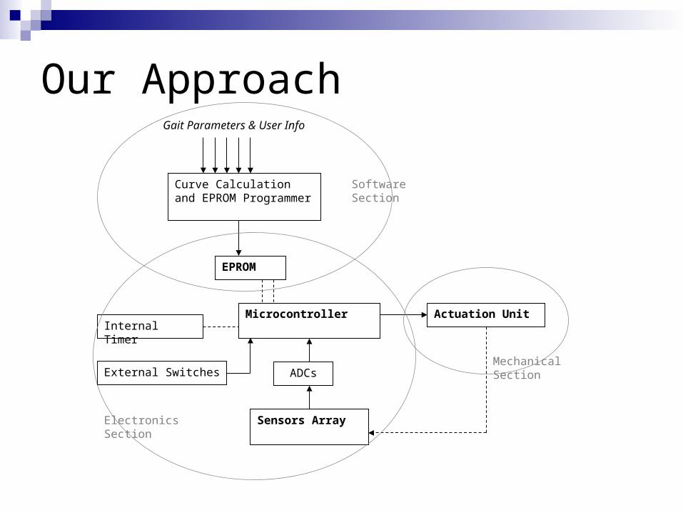
Our Approach
Curve Calculation and EPROM Programmer
Gait Parameters & User Info
EPROM
Internal TimerMicrocontroller Actuation Unit
ADCs
Sensors Array
Software Section
Electronics Section
Mechanical SectionExternal Switches

Software
Resides on the PC Divided into:
Gait CycleCurve GenerationEPROM File
The section as a whole takes the user information, and generates an EPROM file for the microcontroller

Gait Cycle
Walking has four important functions Essential Functions:
Progression Weight Bearing
Non-Essential Functions: Shock Absorption Energy Conservation
For our purpose, we shall only concentrate on the essential functions
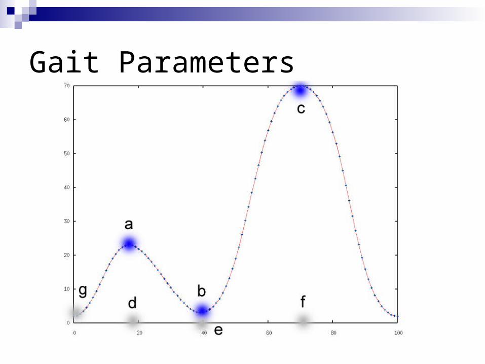
Gait Parameters
Curve Calculation
Time based Parameters (Stride Time) and Physical parameters (Stride Length) not used in this part.
The gait cycle needs to be drawn from the given user parameters of the curve shape.
Wherever parameter not available, use average or nominal value

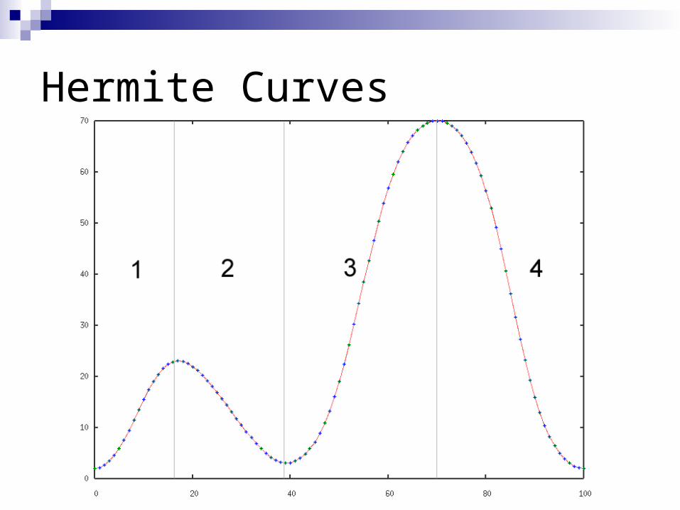
Hermite Curves
Borrow algorithm from computer graphics. Four points for a 2D curve interpolation,
i.e. P1, P2, R1 & R2. Curve is drawn between P1 and P2, with the derivatives R1 and R2 at these points, respectively.
Q(t) = (2t3 – 3t2 + 1)P1q + (-2t3 + 3t2)P2q
+ (t3 – 2t2 + t)R1q + (t3 – t2)R2q
Hermite Curves
EPROM File
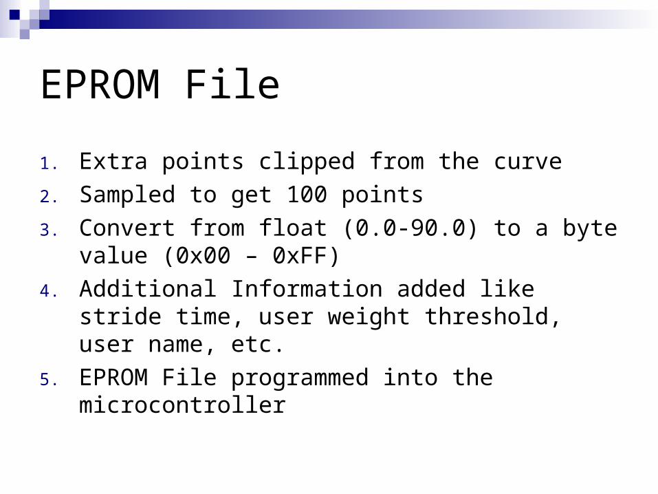
1. Extra points clipped from the curve
2. Sampled to get 100 points
3. Convert from float (0.0-90.0) to a byte value (0x00 – 0xFF)
4. Additional Information added like stride time, user weight threshold, user name, etc.
5. EPROM File programmed into the microcontroller

Electronics
Sensors & Switches ADCs Microcontroller Microcontroller Code EPROM Programmer

Sensors & Switches
Knee Angle Sensor Force Sensor Vibration Sensor P/E Switch Speed Knob Emergency Release Switch

Microcontroller Requirements
EPROM – 128b FLASH - for long program In built ADCs – 3 (external for force and angle) I/O Pins – 25 In Built Timer – 16 bit Low Cost & Availability In-System Programming

Microcontroller I/O Pins
AT90LS8535 Force Sensor – 8 pins Angle Sensor – 8 pins Speed Switch – 1* Pin Emergency Stop Switch – 1 pin P/E Switch – 1 pin Vibration Sensors – 3-4* pins Actuation Unit – 4 pins Status LEDs – 3 pins Programming Mode – 8+3 pins* = may require pins with in-built ADC

Microcontroller Code
Consists of mainly 2 alternating methods, namely actuation control and timer.
Timer generates an interrupt every (stride_time)/100 since 100 points. Also updates desired_angle.
The second method moves actuation one step either side to achieve desired_angle

Microcontroller Code
Other methodsForce ThresholdVibration Start / StopActuation ReleaseUpdate SpeedProgramming Mode
EPROM Programming
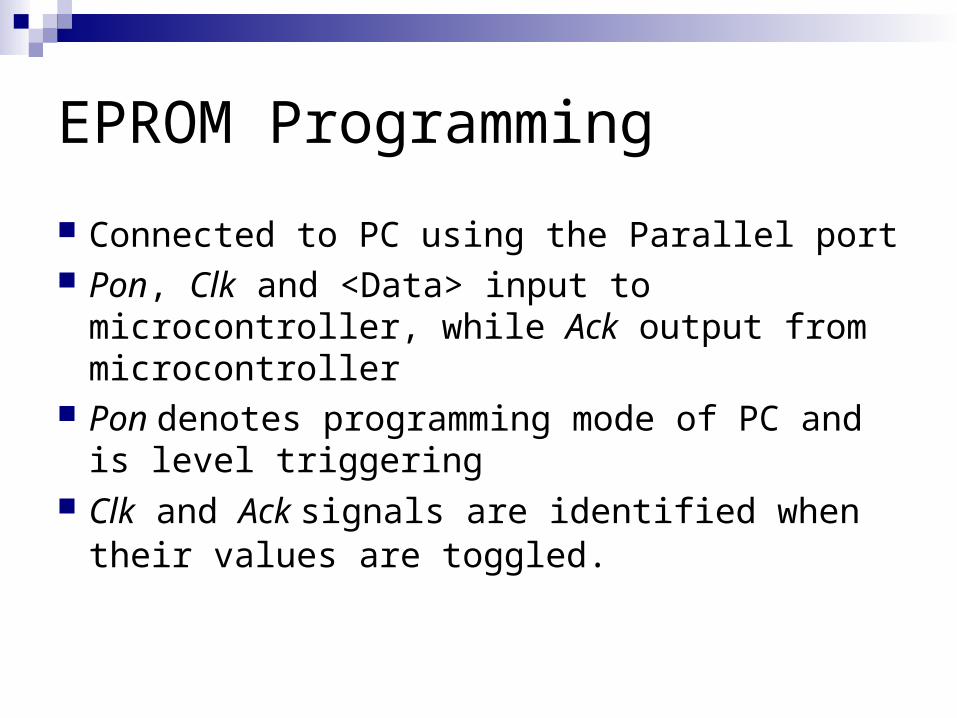
Connected to PC using the Parallel port Pon, Clk and <Data> input to microcontroller,
while Ack output from microcontroller Pon denotes programming mode of PC and
is level triggering Clk and Ack signals are identified when their
values are toggled.

EPROM Programming
Pon
Clk
Data
Ack

Mechanical
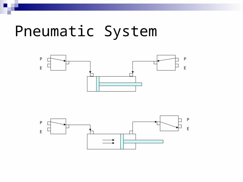
Pneumatic System as the core Hydraulic rejected due to weight Interfaced to PC and tested Flow Valves to control speed Electro-pneumatic valves (3/2), i.e. 3 ports
(exhaust, pressure & output) and total 2 states (output connected to each)
Pneumatic System
P
E
P
E
P
E
P
E

Working of the Leg

Valve Interfacing Circuit

Progress so FarProject Section / Part Progress Description
Progress (in %)
Software
- Curve Calculation Complete, Except for the GUI 90.0
- EPROM File Complete, Except for the GUI 90.0
Electronics
- Sensors Selection and Ordering Done 10.0
- Microcontroller Circuit Selection, Design and Ordering Done 10.0
- Microcontroller Code Design done and Started 33.3
- EPROM Programming Design done 10.0
Mechanical
- Pneumatic System Complete 100
- Interfacing with PC Complete 100
- Interfacing with C Design done 10.0
- Mechanical Leg Design done 10.0

References Clinical Gait Analysis – Davis, R.B. The Mechanics of Gait – Perry, J. Gait Analysis – Kaufman, K.R. Fuzzy Control of Electrohydraulic Above-Knee Prostheses – Ju,
M.S., Yi, S.H., Tsuie, Y.G. & Chou, Y.L. System for Controlling Artificial Knee Joint Action in an Above-Knee
Prosthesis – James, K.B. (US Patent No.- 5571205) Otto Bock website – www.ottobockus.com Computer Graphics: Principles & Practice – Foley, J.D., van Dam,
A., Feiner, S.K. & Hughes, J.F. (Pearson Education) Farnell InOne Catalogue – www.farnellinone.com A Course in Mechanical Measurements and Instrumentation –
Sawhney, A.K. & Sawhney, P. (Dhanpat Rai & Co.) Programming and Customizing the AVR RISC Microcontrollers –
Gadre, D.V. (McGraw Hill) Festo Pneumatic Systems website – www.festo.com

Thank You
Sameer Singh 83 ECE 2k
Shuja Hussain 101 ECE 2k
Raman Agarwal 449 ICE 2k