rola - americanradiohistory.com · rola loud speakers with anisotropic alnico rola co. (aust.) pty....
TRANSCRIPT
Registered at the G.P.O Sydney, fo r transm ission by post as a periodical
" New Rola Speaker-Model 6.K.
The most highly efficient 6" Speaker in Australia. Specially designed to provide extra speaker efficiency for portable battery and vibrator operated receivers.
Will shortly be available to D istr ib u to rs . Re ta il P rice — 41/3.
Rola L OU D S P E A K E R S WI T H A N I S O T R O P I C A L N I C O
Rola Co. (Aust.) Pty. Ltd.,The Boulevard, Richmond, Vic. 116 Clarence St., Sydney, N .S .W .
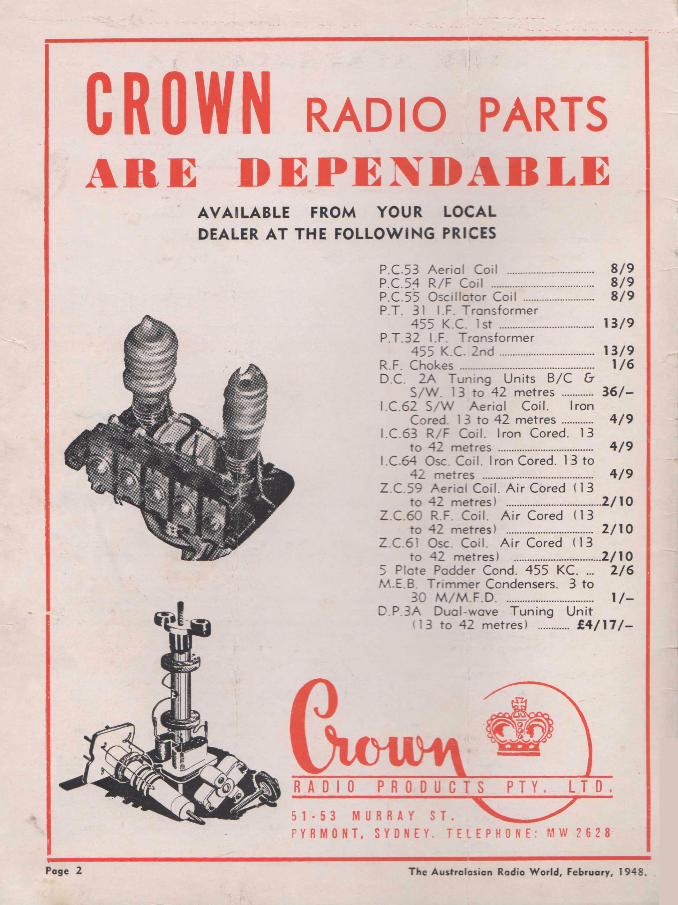
C R O W N RADIO PARTSARE DEPENDABLE
A V A ILA B LE FROM YO UR LOCAL DEALER A T THE FO LLO W IN G PRICES
P.C-53 A e ria l Coil ........................... 8 /9P.C.54 R /F C oil ................................ 8 /9P.C.55 O sc illa to r Coil ...................... 8 /9P.T. 31 I.F. T ransfo rm er
455 K.C. 1st .............................. 1 3 /9P .T.32 I.F. T rans fo rm er
455 K.C. 2 n d .............................. 1 3 /9R.F. C h o k e s ........................................... 1 /6D.C. 2 A Tun ing U nits B /C &
S /W . 13 to 42 metres .......... 3 6 /—I.C .62 S /W A e ria l Coil. Iron
Cored. 13 to 42 metres ......... 4 /9I.C .63 R /F Coil. Iron Cored. 13
to 42 metres .............................. 4 /9I.C .64 Osc. Coil. Iron Cored. 13 to
42 metres ................................... 4 /9Z .C .59 A e ria l Coil. A ir Cored (13
to 42 m etres) ..............................2 /1 0Z .C .60 R.F. Coil. A ir Cored (13
to 42 metres) ........................... 2 /1 0Z.C.61 Osc Coil. A ir Cored (13
to 42 m etres) ................... - ...... 2 /1 05 Plate Padder Cond. 455 KC. ... 2 /6 M.E.B. T rim m e r Condensers. 3 to
30 M /M .F .D ............................... 1 / -D .P.3A Dual-wave T un ing U n it
'1 3 to 42 metres) ......... £ 4 / 1 7 / -
Poge 2 The Australasian Radio World, February, 1948.
T H E A U S T R A L A S I A N
R A D I O W O R L DD e v o t e d e n t i r e l y to T e c h n i c a l R a d i o
A L L - W A V E
and incorporatingA L L - W O R L D D X N E W S
★ EDITOR* PUBLISHER* PROPRIETOR—
A. G. HULL
Balcombe St., Mornington, Vic.
★*■ SHORT-WAVE EDITOR—
L. J. KEAST6 Fitzgerald Road, Ermington,
N.S.W. 'Phone: WL1101 ★
* HAM NOTES By—D. B. KNOCK (VK2NO)
43 Yaako Av., Waverley, N.S.W. ★
★ ADVERTISINGREPRESENTATIVE FOR N.S.W .-
AMALGAMATED PUBLICATIONS PTY. LTD.
•3 PM St., SydneyPhone: B 1077
★★ REPRESENTATIVE IN
QUEENSLAND:JOHN BRISTOE,
Box 82, Maryborough, Q. ★
★ REPRESENTATIVE INENGLAND:
ANGLO OVERSEAS PRESS LTD. 168 Regent St., London, W l.
★* SUBSCRIPTION RATES—
6 issues .................. 5 /312 issues .................. 1 0 /624 issues .................. £1Post free to any address in
the world.
Address for all correspondence: AUSTRALASIAN RADIO WORLD
Balcombe St. Mornington
Victoria
Vol. 12 FEBRUARY, 1948 No. 9
C O N T E N T S
TECHNICAL—Stir in Hi-Fi Circles .................................................... 5W alkie-Talkie ........................................................... 9High Fidelity From CrystaJ Pickups ....................... 15Hints and Tips .................* ..............................,.......... 18Home-Wound Power Transformers ......................... 19Converters for "S ix " and "T e n " ............................ 24Wanted— An Inventor ............................................... 27The "Teleconda" Powerport ..................................... 31Ham Notes .................................................................. 35
SHORTWAVE REVIEW—Notes From My Diary .................................................. 38
THE SERVICE PAGES—Speedy Query Service ................................................. 42
EDITORIALI t is a lot o f fu n bein g a pu blisher of a tech n ical rad io
m agazin e but th ere are one or tw o tight corn ers w hich you have to be ca re fu l to keep out of.
T o g iv e you tw o exam ples, I m ight m ention th a t quite a num ber o f letters h ave been rece iv ed la te ly w hich tend tow ard s being abusive (in a n ice w ay , o f course) because I w on ’t put dow n in b lack and w hite w hich I th in k is th e best p ick-up, and because I h av en 't yet published an a rtic le on how to m ake your ow n w ire recorder.
T h e pick-ups a re a prop er head ach e. F o r days past I h ave been ru nn in g one o f the latest type of am plifiers w ith triodes and in v erse feedback, try in g out in tu rn the “L exin g ton ” and “C on noisseur” pick-ups ag a in st m y old fa v o u rite cry sta l job w hich I picked out o f a batch a fte r ru nning them on frequency test record s w ith a v .t.v .m . in circu it. T h e re is no doubt about the latest E n glish pick-ups scrap in g highs off the records w hich you n ev er h ear w ith o rd in ary pick-ups, but it is h ard to say w hether it can be consid ered d esirab le , esp ecially w ith ord inary records. B y cu ttin g the h ighs you can only get back to w here you started . A tuned scratch filter seem s to be th e only answ er.
M a k in g up a w ire record er a t home is a f a r m ore com plicated jo b th an you m igh t im agin e from looking at a d ia gram w hich h as been sketched out to show the fu nd am entals o f the id ea. Y ou can ’t ju st use any old bits o f w ire and you need a lot o f precision w ork o f a m echan ical n ature.
— A . G . H U L L .

CHOKES • TRANSFORMERS • COILSFILTER FILAM ENT LINE
AUDIO & AUTO SPEAKER LINE FILTER VIBRATOR AUDIO & VIBRATOR ETC.
FILTER CHOKESThese quality com ponents in corp orate heavy copper w ire wound on trolitul bobbins The use of trolitul elim inates electrolysis, ensuring m uch longer effective life.
Sizes 21 x 2% x 1%Type TC65 30 Henries 400 ohms
D.C. Res. 50 M /A 13/6Type TC60 30 H enries 250 ohms
D.C. Res. 100 M /A 13/6Type TC80 30 Henries 150 M /A 21 /- Type TC81 30 H enries 200 M /A 25 /-
Specially designed for use in con junction with speakers.
Sizes 21 x 2 x l i Type TC66 20 H enries 650 ohms
D.C Res. 60 M / A ................ 10/-
AUDIO CHOKESType TA4 100 Henries 1000 ohms
D.C Res. 25 M /A 18/6
VIBRATOR CHOKESSpecially designed and engineered to give m axim um perform ance in vibrator units. The core and winding are p roperly balanced to suit the exactin g con ditions for effectively filtering a 'ib ra to r
Size 22 x 2% x It ['vpe TC58 Low Tension 3 am ps 50
M /H 5 ohm D.C. Res. 15/-t vpe TC70 High Tension 50 Henries
450 ohm D C Res 75 M /A 15/-
FILAMENT TRANSFORMERSThese filament transform ers are of the midget type and have a carryin g cap acity of 7 w atts and can be procured in any secondary voltage. The prim ary winding is for 240 volts and has been flash tested between winding and earth qf 1000 volts.
Size 21 x 2 x 15 Type TP1 2.5 volts, 2 am ps, 7 w att 11/6 Type TP2 4 volts, 1 amp, 7 w att 11/6 Type TP3 6.3 volts, 3 am ps, 7 w att 11/6 Type TP55 6.3 volts, 3 am ps, 15
w att .................... 12/9(N ote: L ast item —size 2| x 2% x 12)
SPEAKER TRANSFORMERSLam inated w ith high grade stalloy iron and com plete w ith mounting clamp, are available in a range to m atch any output valve and speaker combination, both single and push pull.
Sizes 21 x 2 x 15 Type TS23 Single low im pedance
t r i o d e ..................... 10/-Type TS24 Single high im pedance
triod e .............................. 10/-Type TS25 Push Pu ll low im ped
ance t r i o d e ........................ 10/6Type TS26 Push Pull high im ped
an ce t r i o d e ............................... 10/6Type TS27 Single low im pedance
pentode ................. 10/-Type TS28 Single high im pedance
p e n t o d e ................................ 10/-Type TS29 Push Pull low im ped
ance p e n to d e ................................... 10/6Type TS30 Push Pull high im ped
ance pentode 10/6
AUTO TRANSFORMERSSuitable for valve replacem ent.
Size 21 x 2 x l i Type TP80, 6.3 volt, 4 volt, and 2.5
volt 11/6
AUDIO TRANSFORMERSLong experience in the production of highly efficient transform ers combined with extensive research into raw m aterials and design has resulted in the production of Audio transform ers of excellen t perform ance and com plete reliability.
Size 23 x 2% x 12 Type TB42 A class single, 3 to 1
ratio ............... 21 /-Type TB43 A class Push Pull, 3 to
1 ratio .................................. 22/6Type TB44 B class Push Pull, 1 ̂ to
1 ratio 21 /-
VIBRATOR TRANSFORMERSDesigned to supply correct voltages and cu rren t for the receiver, the finest grade m aterials procurable are used in th eir construction. They are given individual tests during m anufacture, as well as rigid tests and inspection before shipment.
Sizes 22 x 2% x 12 Type TP81 135 volt. 6 v o l t ...............17/6
LINE FILTERThe R.C.S. Line F ilte r is specially designed and constructed to elim inate all noises which occu r by reason of feedback from pow er m ains . . . electric m otors . . . refrigerators . . . elevators
. . sub-stations . . . high tension wires . . . irons . . . and jugs! Easy to install —it connects betw een the radio and pow er point.
LINE FILTER COILThis choke is the same as used in the R.C.S. L ine F ilte r and has a carryin g capacity of 1 amp. Wound on llin form er with m ounting lugs attached
SPEAKER TRANSFORMER REPLACEMENT COILSFeatu res im portant advancem ent in design. H eavier gauges of w ire wound on moulded trolitul form er afford com plete insulation between windings and core under full tropical conditions at high humidity. This new speaker winding relam inates easily with no possibility of dam age to windings by sharp corners of laminations. Burn outs and deterioration due to electro lysis are definitely minimised, due to the unique moulded bobbin construction, available in com plete range to suit any output valve.Type F132 Single low impedance
triode 5/6Type F133 Single high im pedance
triode 5/6Type F134 Push Pull low im ped
ance triode 6 / - Type F135 Push Pull high im ped
ance triode 6 /- Type F136 Single low impedance
pentode 5/6Type F137 Single high impedance
pentode 5/6Type F138 Push Pull low im ped
ance pentode 6 /- Type F139 Push Pull high im ped
ance pentode 6 /-
R. C. S. R A D I O P T Y . L T D174 CANTERBURY ROAD, CANTERBURY, N SW ., AUSTRALIA

STIR IN HI-FI CIRCLESDistortion Standards Upset by Tnodes with Feedback
A MINOR sensation has happened in amplifier circles since the news has got around that the use of in
verse feedback with triode amplifiers gives a reduction in distortion which is noticeable to the ear fn spite of previous acceptance of a fable that distortion from 2 to 5 per cent could not be distinguished by the human ear.
The reason for all the hubbub can be traced back to the circuit which we published in our August, 1947, issue, having reprinted same as an item of interest from the English “W ireless World” of April and May, 1947. Designed by a Mr. D. T. N. Williamson, late of the M ar
coni-Osram valve factory, this circuit was presented as featuring low distortion, but since it is so easy to get amplifiers with low distortion this circuit did not arouse any terrific amount of enthusiasm until one or two of our deepest-dyed quality enthusiasts actually built it up and got to work on it. Then the startling fact was revealed that in spite of all tales which have been current to the contrary, the human ear can tell the difference when distortion is reduced from 2 or 3 per cent, to less than a quarter of a per cent. Possibly phase sh ift has something to do with it, too, for this amplifier has a feedkack circuit which means that trouble is
encountered if the phase shift is not held to a minifnum. Having taken trouble in the design to minimise phase shift in order to get the feedback circuit working properly, the nett result of the low harmonic distortion, wide frequency range and small phase shift is something which is appreciated as soon as it is heard.
O.P.T. Important
Essential fo r the proper operation of the amplifier is an efficient output transform er with low leakage inductance and high primary inductance. On account of the in-
(Continued on next page)
The Australasian Radio W orld, February, 1948. Page 5
STIR(Continued)
terest aroused by the circuit the Red Line people went into production with a special output transform er to suit this type of circuit. Known in the Red Line brand as type A F10, this transform er is a massive job, weighing 7 lbs. and listing a t £6. W ith a frequency response of ■within .2 db. from 20 to 30,000 cycles per second this output transform er is the last word in such things.
Radiotron Effort.
The original English amplifier circuit used English valves of types KT66 and L63, and when reprinting the article we took the chance and mentioned that, although not identical, it appeared that the local 807 and 6J7G types could be used as substitutes. So much interest has been shown in the circuit, however, that the wide-awake Radiotron Applications Laboratory got on to the job and made tests on the 807 to prove its suitability for operation under the conditions imposed in the English circuit, viz., about 400 volts on both plate and screen. Working on the amplifier seems to have aroused keen enthusiasm in Messrs. Langford- Smith and Aston of the Radiotron organisation and so they have redesigned the circuit to suit local conditions and available valve types, the circuit being published recently in “Radiotronics.”
Our local engineers have introduced one or two interesting modifications, the most noticeably being the use of the twin triode type 6SN7GT, thereby making two valves do the work of four in the original circuit.
The Radiotron engineers are not given to the making of rash statements, and therefore it is a powerful testimonial to the performance
Working from the English c ircuit, a Belgian engineer hat developed another c ircu it embodying triodes w ith inverse feedback. Watch for i t in next
month's issue.
of the amplifier when they put it down in black and white th at this amplifier “is by fa r the best which we have ever tested.” Summing up, they state, “I t not only gives extraordinary linearity and lack of harmonic or intermodulation distortio n , but is comparatively simple, and. involves no special problems except the choice of output transtransform er.”
ReflectionsThose who have kept in close
touch with progress in amplifier circuit design find it a little hard to understand one or two points about the latest circuit. In the first place, why have the main features of the amplifier been so consistently passed over in days gone by? For example, the circuit uses a direct-coupled phase-splitter of the type first published by us in our May, 1940, issue. We battled for this cuircuit fo r several years, fe a turing it in such circuits as the “Super Seven” in June, 1941, but nobody seemed over-impressed with the claims made fo r the low phase-shift in this method of obtaining push-pull operation. Then the m atter of applying inverse feedback to triodes is not ehtirely new, having been featured, fo r example, in an amplifier which we detailed in our issue of April, lg42. This amplifier used 2A3 triodes in push-pull with inverse feedback, with resistance-coupled push-pull driver stage, using the 6N7. Incidentally it mentioned in this article that the 2A3 type triode output valves were being operated with 400 volts on the plates, apparently without ill effect.
Mention of which leads us to the next reflection: why use the big beam power valves and then tie the plates, screens and other internal elements together to form a triode when there are so many perfectly good triodes available as such. Here in Australia the low price of the surplus munitions type 807 valves means that they are cheaper than the triodes, but this is hardly likely to have been a consideration for Williamson when he was working out the original English circuit.
Some Other NewsThere are other things which are
causing added interest in high- fidelity circles. One of these is the announcement that J . H. Magrath& Co. recently landed a small ship
ment of English “Connoisseur” pick-ups which are of the miniature moving iron high-fidelity type of a kind which has not been prominent in Australia in the past. A short time ago news was received from Mr. Rom Errm ann of the Lintas Advertising Agency in London that these English “Connoisseur” pick-ups were the answer. Mr. Errmann was a prominent member of the Sydney Recorded Music Society in the good old days of about 1934 when he was associated with Gordon & Gotch in Sydney. Knowing that Mr. E rrmann would not say such things unless the pick-up was something out of the ordinary, steps were taken to get a small shipment through, ju st a dozen, and reserved fo r “Radio World” enthusiasts, as mentioned in our query columns in the November issue. There was a scramble fo r these samples, and they have proved so successful that arrangements are now in hand fo r their importation in quantity. Unfortunately we were a little astray in our initial announcement of these pick-ups, as we said that they did not require a pre-amplifier. W hilst this may be strictly correct, i t gives the wrong impression as a tone- correction pre-amplifier stage is necessary. The output from the pick-up, a fter being stepped up in the input transform er is about .7 of a volt, but this is flat, and is not boosted on the lows as is necessary to compensate fo r recording technique. However, the pre-amplifier is a comparatively simple one and should not be allowed to frighten anyone.
Latest news from England is that the crystal pick-up people are recognising the threat of the high- fidelity types of moving iron and moving coil pick-ups and are taking the necessary steps to uphold their claims that crystal pick-ups are best. I t seems th at the competition between the types will result in improvements.
English Speakers.
English manufacturers have long claimed that their loudspeakers have good high-note re sponse and several brands of high fidelity speakers have been available on the English market. A few of these have trickled through to the Australian market, some undoubtedly good speakers, others not
Page 6 The Australasian Radio World, February, 1948.
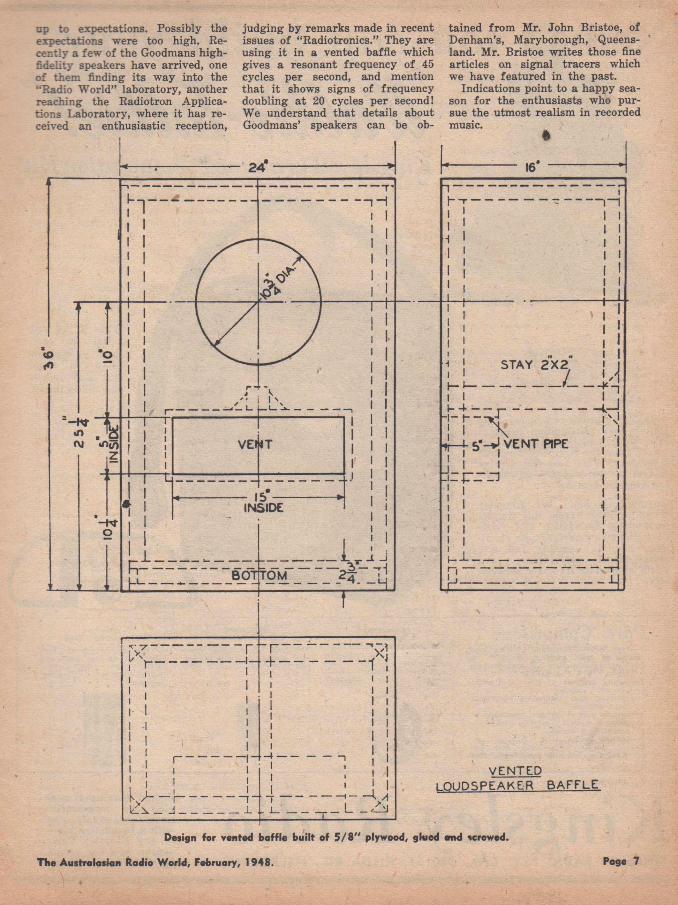
up to expectations. Possibly the expectations were too high. Recently a few of the Goodmans high- fidelity speakers have arrived, one of them finding its way into the “Radio World” laboratory, another reaching the Radiotron Applications Laboratory, where it has re-
judging by remarks made in recent issues of “Radiotronics.” They are using it in a vented baffle which gives a resonant frequency of 45 cycles per second, and mention th at it shows signs of frequency doubling a t 20 cycles per second! We understand that details about
tained from Mr. John Bristoe, of Denham’s, Maryborough, Queensland. Mr. Bristoe writes those fine articles on signal tracers which we have featured in the past.
Indications point to a happy season fo r the enthusiasts who pursue the utmost realism in recorded
Design for vented baffle bu ilt of 5 /8 " plywood, skied and 'crewed.
The Australasian Radio World, February, 1948. Page 7
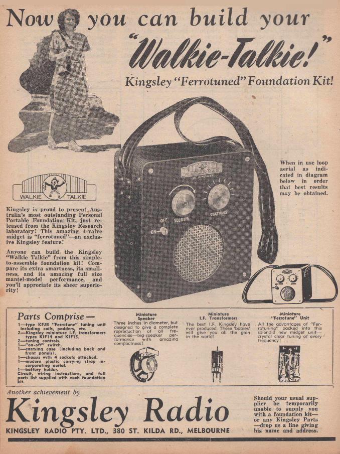
Parts Comprise —1— type KFJB "F e rro tu n e " tun ing u n it
inc lud ing coils, padders, etc.2— Kingsley m in ia tu re I.F. transform ers
types K IF14 and KIF15.2— tun ing controls.1— " o n - o f f " switch.1— carry ing case (inc lud ing back and
fro n t pane ls).1— chassis w ith 4 sockets a ttached.1— modern p lastic carry ing strap in
corpora ting aeria l.1— b a tte ry holder.C ircu it, w iring instructions, and fu ll parts lis t supplied w ith each founda tion k it.
M in ia tu reSpeaker
Three inches in d iam eter, but designed to g ive a complete reproduction o f a ll f re quencies— bi.g-speaker perform ance w ith am azing compactness!
M in ia tu re I.F. Transform ers
The best I.F. K ingsley have ever produced. These 'babies' w ill g ive you a ll the gain in the w orld !
--------------------------- v■Miniature
"F e rro tu n e " U n itA ll the advantages o f "F e r- ro tu n in g " packed in to this splendid new m idget u n it— crysta l c lear tu n in g o f every frequency!
Should your usual supplier be temporarily unable to supply you with a foundation kit— or any Kingsley Parts — drop us a line giving his name and address.
Now you can build your
Kingsley “ Ferrotuned” Foundation Kit!
When in use loop aerial as indicated in diagram below in order that best results may be obtained.
Another achievement by
Kingsley RadioKINGSLEY RADIO PTY. LTD., 380 ST. KILDA RD., MELBOURNE
Kingsley is proud to present Australia ’s most outstanding Personal Portable Foundation Kit, ju st released from the Kingsley Research laboratory! This amazing 4-valve midget is “ferrotuned”— an exclusive Kingsley feature!
Anyone can build the Kingsley “Walkie Talkie” from this simple- to-assemble foundation k it! Compare its extra smartness, its smallness, and its amazing full size mantel-model performance, and you’ll appreciate its sheer superiority !
WALKIE TALKIE

LATEST KIT RELEASE:— PART 2
"WALKIE-TALKIE" by KingsleySelf-contained battery-operated "personal" portable receiver
IN the December issue we published preliminary details of the Kingsley “W alkie-Talkie” receiver and we present the
•corfcluding article giving the point to point wiring, schematic diagram, parts list and alignment
In our December issue in Part One of the description of the Kingsley "W a lk ie -T a lk ie ," we included a c ircu it diagram to illustrate certain points. It should be clearly understood that the circuit was only a provisional basic c ircu it and not to be regarded as the fina l, fu lly - checked circuit from which to build the "W a lk ie -T a lk ie ." The circuit issued with each "W a lk ie -T a lk ie " foundation k it
is shown on this page.
I
data, also photos of the receiver in various stages so that little difficulty will be encountered even by the most inexperienced builder in constructing this outstanding personal portable.
Loop Aerial
In keeping with current trends, the Kingsley Miniature Ferrotune Unit was produced to incorporate a loop aerial of low impedance. The area of the loop, within limits, is not extremely critical and for general usage the loop has been designed and included in the shoulder strap. For optimum results, it is advisable to maintain the loop as near as possible to a
This is Part Two of the description of the Kingsley "W a lk ie -T a lk ie " which commenced in our December issue and intended to be completed in our January issue. Owing to the intervention of the holidays, i t was not possible to have the material ready for publication in our last issue. The following article should b'e read as a continuation of tha t published
in December.
circle and in a vertical plane. Obviously, if the shoulder strap loop is twisted together or not representing as fa r as possible a circle, the inductance and the impedance of the loop is altered, fo r the reason that the induced voltage (example— pick-up) is propor-
(Continued on next page)
PERSONAL PORTABLE
KIFI5
K.R.3. 5 0 0 0 A
« 7 SV
O F F -O N SWITCH
I CK-
SHOULDER STRAP AERIAL
I R 5 KI FI 4
-W fr-2-
KINGSLEY WALKIE _ TALKIE
The Australasian Radio World, February, 1948. Page 9
W ALKIE TALKIE(Continued)
tional to loop area. The low impedance loop has the same directional properties as the ordinary high impedance loop.
The following procedure should be followed to enable easy wiring of the receiver: (1) Connect the centre shields of all tube sockets to the chassis, together with the following points: Pin No. 1 of 1R5, 1T4 and 1S5 sockets, and Pin No. 5 of 3S4 socket. (.2) Connect together the following: Pin No. 7 of 1R5, 1T4, 1S5 and Nos. 1 and 7 of 3S4 sockets. These are the filament positive connections. (3) Connect together the RED lugs of both I.F . Transform ers and to Pin No. 4 of 3S4. (4) Bend and solder together the following points: (a) Pin 2 of 1R5 and plate (green) lug of K IF14 (1st I .F . ) ; (b) Pin 6 of 1T4 and grid (brown) of K IF 14 ; (c) Pin 2 of 1T4 and plate (green) of K IF15 (2nd I .F .) ; (d) Pin 3 of 1S5 and grid (brown) of K IF15. (5) Connect 2-megohm resistor between the filament (black) lugs of K IF14 and K IF15. (6) Connect 10-megohm resistor between pin 6
of 1S5 and chassis. (7) Connect 10,000 ohm resistor between pin 3100,000 ohm resistor between pin of 1T4 and H.T. (R E D ) lug of 4 of 1R5 and chassis. (8) Connect K IF15. (9) Connect 100 mmfd.
condenser between F il. of K IF15 and chassis.
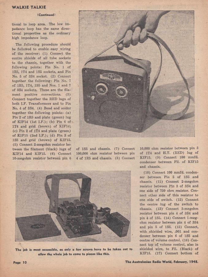
r
The job is most accessible, as only a few screws- have to be taken out to allow the whole job to come to pieces like this.
(10) Connect 100 mmfd. condenser between Pin 5 of 1S5 and chassis. (11) Connect 2-megohm resistor between Pin 3 of 3S4 and one side of 750 ohm resistor. Connect other side of this resistor to one side of switch. (12) Connect the centre lug of the switch to chassis. (13) Connect 3-megohm resistor between pin 4 of 3S4 and pin 4 of 1S5. (14) Connect 1-megohm resistor between pin 4 of 3S4 and pin 5 of 1S6. (15) Connect, with shielded wire, .001 and condenser between pin 6 of 1S5 and centre of volume control. (16) Connect top of volume control, also in shielded wire, to Fil. (B lack) of K IF15. (17) Connect bottom of
Page 10 The Australasian Radio World, February, 1948.
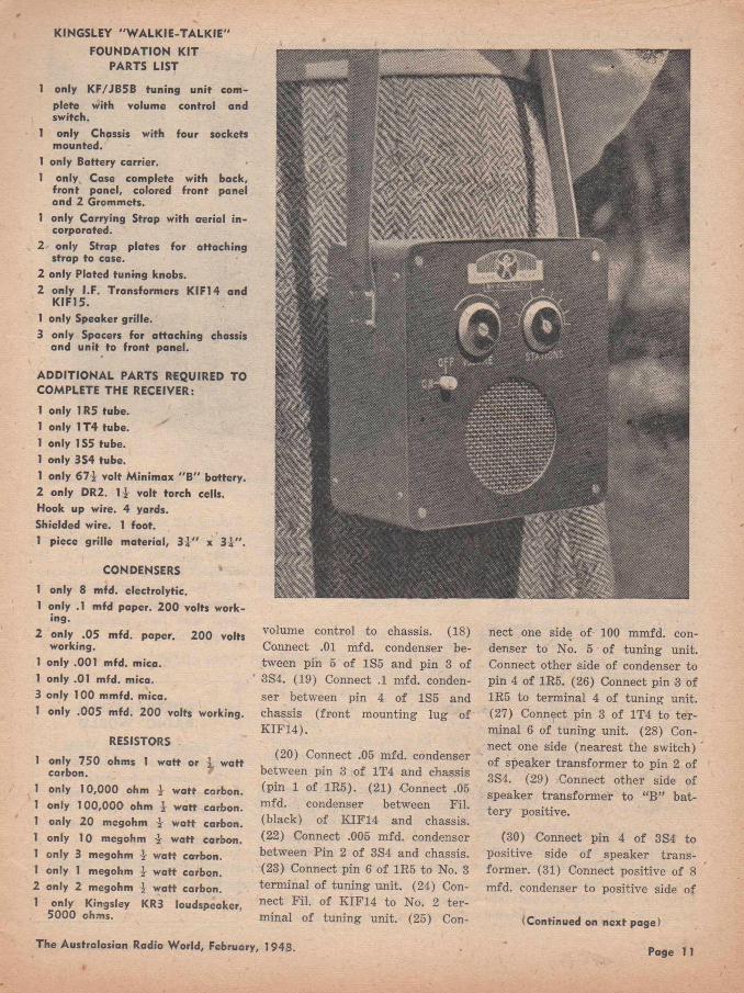
1 only KF/JB5B tuning un it complete with volume control and switch.
1 only Chassis with four sockets mounted.
1 only Battery carrier.1 only Case complete with back,
fron t panel, colored fron t panel and 2 Grommets.
1 only Carrying Strap with aerial in corporated.
2 only Strap plates for attaching strap to case.
2 only Plated tuning knobs.2 only I.F. Transformers KIF14 and
KIF15.1 only Speaker grille.3 only Spacers for attaching chassis
and unit to front panel.
ADDITIONAL PARTS REQUIRED TO COMPLETE THE RECEIVER:
1 only 1R5 tube.1 only 1T4 tube.1 only 1S5 tube.1 only 3S4 tube.1 only 67-J- volt M inim ax " B " battery.2 only DR2. 1-J- volt torch cells. Hook up wire. 4 yards.Shielded wire. 1 foot.1 piece grille material, 3-J-" x 3 1 ".
KINGSLEY "W ALKIE-TALKIE FOUNDATION KIT
PARTS LIST
nect one side of 100 mmfd. condenser to No. 5 of tuning unit. Connect other side of condenser to pin 4 of 1R5. (26) Connect pin 3 of 1R5 to terminal 4 of tuning unit. (27) Connect pin 3 of 1T4 to terminal 6 of tuning unit. (28) Connect one side (nearest the switch) of speaker transform er to pin 2 of 3S4. (29) Connect other side of speaker transform er to “B ” battery positive.
(30) Connect pin 4 of 3S4 to positive side of speaker transformer. (31) Connect positive of 8 mfd. condenser to positive side of
(Continued on next page)
Page 1 1
CONDENSERS 1 only 8 mfd. electrolytic.1 only .1 mfd paper. 200 volts work
ing.2 only .05 mfd. paper. 200 volts
working.1 only .001 mfd. mica.1 only .01 mfd. mica.3 only 100 mmfd. mica.1 only .005 mfd. 200 volts working.
RESISTORS
1 only 750 ohms 1 watt or -V watt carbon.
1 only 10,000 ohm -J- w att carbon. 1 only 100,000 ohm -]r watt carbon. 1 only 20 megohm i watt carbon. 1 only 10 megohm watt carbon. 1 only 3 megohm i watt carbon.1 only I megohm i watt carbon.2 only 2 megohm -] watt carbon.I only Kingsley KR3 loudspeaker,
5000 ohms.
volume control to chassis. (18) Connect .01 mfd. condenser between pin 5 of 1S5 and pin 3 of 3S4. (19) Connect .1 mfd. condenser between pin 4 of 1S5 and chassis (front mounting lug of K IF 14).
(20) Connect .05 mfd. condenser between pin 3 of 1T4 and chassis (pin 1 of 1R5). (21) Connect .05 mfd. condenser between Fil. (black) of K IF14 and chassis.(22) Connect .005 mfd. condenser between Pin 2 of 3S4 and chassis.(23) Connect pin 6 of 1R5 to No. 3 terminal of tuning unit. (24) Connect Fil. of K IF14 to No. 2 te rminal of tuning unit. (25) Con
The Australasian Radio World, February, 1948.

W ALKIE TALKIE(Continued)
speaker transformer. (Lay this condenser against front panel on the left side of the speaker.) (32) Connect negative side of the 8 mfd. condenser to chassis. (33) Connect remaining side of switch to “A” negative. (34) Connect pins 1 and7 of 3S4 to “A” positive. (35) Connect junction of 2 meg. resistor and 750 ohm resistor to “B ” negative. (36) Connect loop aerial ends to terminals No. 1 of tuning unit. (37) Carefully check your wiring, making sure that no leads can foul the movement of the tuning unit. The unit and IF . transformers have been thoroughly lined and tested before leaving the factory and the receiver should now operate satisfactorily.
Alignment Data
Units are aligned a t the Kingsley factory by crystal oscillator standards, and then given a generator test for sensitivity and image ratio; hence when the customer receives the Ferrotune, it is pre-set and should under average layout, need no further adjustment. However, due to the capacitance variation occurring between the test chassis and to that in which it is eventually wired, a compensating adjustment of the unit’s trimmers may be necessary. I t is important to note that this variation will be small and only slight alteration should be a ttempted. The oscillator trimmer is below, and that of the signal circuit aerial on the right, viewing the Ferrotune from the back of chassis.
The aerial or signal circuit' is adjusted for maximum signal response a t the H .F. end of the band. This operation is best carried out on a distant station around 1500 kC/s. On NO ACCOUNT should
the tuning cores or the shunt inductance core be shifted. I f this warning is unheeded, eventual misalignment will occur and the unit will have to be returned to an authorised dealer.
Conclusion
This Kingsley “W alkie-Talkie” personal portable has met with real approval and many sales have been made to a large number of satisfied users. As a m atter of fact, the whole pre-Christmas production of the factory was completely sold out and, now that production is again in full swing, shoals of congratulatory letters from enthusiastic home constructors are pouring into Kingsley Radio Pty. Ltd. An excerpt from one letter is: “As I pen this note I have my Kingsley ‘W alkie-Talkie’ beside me. It is one of the finest all-round sets that I have seen.
Tuning and tone is superb and the ‘Ferrotuning’ system is sharp and works smoothly. The tone of the Kingsley KR3 speaker is outstanding.” We tender congratulations to Kingsley Radio on their achievement with this outstanding personal portable.
AUSTRALASIAN RADIO WORLD
Australasian Radio World is again in short supply, due to the necessity for paper conservation under economic meacures applied by the Federal Government in its effort to assist Britain.
It is, therefore, suggested tha t you ask your newsagent to reserve your copy.
Page 12 The Australasian Radio World, February, 1948.
"CONNISEUR"PICK-UPSpresents
the revolutionary crystalpick-up
T 10This superb model, designed for direct
connection to existing equipment, is for the expert who desires THE BEST.
Its full brilliance of the highs, its clarity in the bass, its newest cast aluminium arm, its twelve months' guarantee, and its low price make it—
THE PICK-UP FOR YOU
The AUSTRALIAN RECORD COMPANY of Sydney, in conjunction with CONNISEUR, have developed the "lifelong" sapphire-tipped needle for the T10. Another exclusive feature, to ensure many thousand playings without requiring a needle change.
Write today for detailsKELM AN INDUSTRIESBOX 40, H A W T H O R N , E.2. M ELBOURNE, V IC T O R IA .
Music for the People by"C O N N IS EU R "
P.S.— This model is equipped with the unbreakable crystal cartridge. Why not write for your technical brochure? For the best— after test— specify CONNISEUR.

HINTS FOR CONSTRUCTORS
IN ST A B IL IT Y is a trouble often encountered in compact mantel sets, because it is simply impossible to avoid all inductive
and capacitive stray couplings in such a crammed space. There are, however, two simple methods which, according to the case, are
By
PAUL STEVENS
sure to be a cure for your problem child: I f oscillation occurs only on the lower frequency end of the broadcast band, between about 700 kC and the 550 kC end of the dial, it is almost certain to be caused by inter-action of the aerial primary coil and the I F channel. Certain brands of aerial coils resonate a t a frequency pretty close to the standard IF , and if the tuning of the grid coil toward the end of broadcast band approaches that frequency too, enough energy might be fed back to cause the set to oscillate. In most cases, a 5000- ohm resistor between aerial and chassis will stabilise the set without causing an undue loss of gain, in fa ct the loss is so small that it can only be detected by instruments and not by the human ear. Another distinctive feature of this type of instability is also the fact that it is accentuated by certain lengths of aerial, the capacity of which tunes the aerial coil exactly to the IF (usually between 15 and 20 fe e t). A sure-fire method against general instability is to reverse the phase of one of the IF circuits, usually the plate coil of the converter. This turns positive into negative feedback, as long as two stages are involved and makes the set completely stable. However, we often encounter a big loss of gain that way. This is due to the often-present capacitive coupling between the hot ends of the IF transform er in addition to the inductive coupling. These small capacities, caused by the leads from the top coil passing the bottom coil on their way down to the terminals, are normally in phase
and increase the coupling; but they get out of phase as soon as the coils are reversed and form a more or less strong opposition. This loss of coupling has to be made up fo r by increasing the inductive interaction of the coils. As I described in another article, this can be achieved by putting one-or both coils of the particular IF transform er on the inner setting, meaning to screw the slugs right through the coils till they come out on the inside, between the coils, and tune them to the IF in this position. The iron between the coils then gives additional coupling, which restores the normal gain. I f a common cathode bias is
used for both converter and IF valve, the bypass condenser should not be less than .5 mf. Single stage feedback involving only the IF Valve can hardly occur, if the simplest rules fo r layout and wiring are observed. I f you have to use a single-ended valve and encounter instability, it serves you right. The best remedy is to throw the valve out of the window.
Minimum Bias for Sets Without AVC
These sets use more often than not a bias volume control consisting of a 2500 to 500 ohm potentiom eter in the combined cathode return of converter and I F valve. Usually there is a small wire- wound resistor in series with it to provide the initial bias, when the volume is fully turned on. I f this resistor is omitted, the volume will fa ll off again when the control is advanced past a certain optimum point and the bias approaches zero.
For four-valve sets, this optimum position of the control is rather critical, as i t is essential with these sets to get every ounce of gain out of them, but a t the same time the falling off of volume past that point is an undesirable feature. Now the initial resistance of a potentiometer of this kind varies a great deal; there is often 100 or more ohms to go, even with the wiper hard up against the stop, while in other cases the resistance is almost zero. I t is therefore desirable to have a means to individually adjust your bias volume control fo r maximum gain without dropping off. The RCS volume control with its contact ring provides an excellent and simple means to achieve this very end: Fig. 1 shows how it is done. The potentiometer, installed without additional resistor, is set to m aximum gain and the position marked. I t is then turned back and with a pair of long-nose pliers the contact ring is bent up vertically ju st past the point of maximum gain. The bent-up portion makes an excellent stop for the wiper arm and a t the same time leaves the right amount of resistance in the circuit for initial bias.
NEED FOR IGNITION SUPPRESSION
Vehicles fitted for radio communication in the fighting services incorporate effective suppression of ignition radiation. All metal joints are carefully bonded and wiring of any kind fully screened. Result is the ability to work even with comparatively weak signals whilst on the move. That’s how things should be and in the future world of television, etc., there will need to be more than a passing thought for the problem of ignition QRM from nearby and even distant motor vehicles. F.M. will, of course, take the listener a long way toward QRM-free sound reproduction, but man-made interference can cause havoc with video screens. It should be law that electrical appliances are produced with integral QRM filters, and .there is no reason why car manufacturers should not include suppression as standard practice.
r.V .V .V A V A W .V .W .V A V .Page 14 The Australasian Radio W orld, February, 1948.
HIGH FIDELITY FROM CRYSTAL PICK-UPSIT is not realised as widely as
it should be that the piezoelectric crystal pickup operates on a principle fundamen
tally different from that underlying the moving coil, or other electro-magnetic types of pickup, and that attempts to treat it on the same- footing are foredoomed to failure. I t is the purpose of this article to discuss this difference, and to show that, combined with suitable electrical networks, the crystal pickup can give results a t least as good as those obtainable from the electro-magnetic types, together with the advantages of high sensitivity, and the
By
L. J. WHEELERand
K. G. LOCKYER, B.Sc.(Research Dept., Cosmocord Ltd.)
possibility of dispensing with coupling transform ers, hum pickup and other troubles.
C o m m e r c i a l recordings are generally made with electromagnetic cutting heads. I t is a characteristic of this type of head that constant input to the recording amplifier (here assumed to be ljn ear), does not produce constant amplitude of vibration, but constant “velocity” of the stylus point. This velocity is the rate of change of displacement as the cutter passes through its mid posi
That it is possible to get high fidelity from gramophone recordings without pick-ups which need pre-amplifiers is claimed in this article from England. It is interesting to note that the Acos (usually known as Cosmocord) pick-ups are now being handled in Australia by the well-known firm of Amplion Pty. Ltd., and doubtless the high-fidelity types such as the Acos GP12 will soon
be available here.
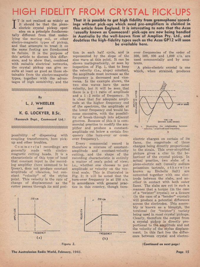
tion in each half cycle, and is represented by the slope of the sine wave at this point. I t can be shown mathematically, or seen by inspection of F ig . 1, that to keep the velocity (i.e., slope) constant, the amplitude must increase as the frequency is decreased and vice- versa. In the example shown, the two sine waves have the same velocity, but it will be seen that there is a 2 : 1 ratio of amplitude and a 1 : 2 ratio of frequency. It is clear that for adequate amplitude at the higher frequency end of the spectrum, the amplitude at the lower frequency end would become excessive, with the possibility of break-through into adjacent grooves. Because of this it is commercial practice to modify the amplifier and produce a co.nstant- amplitude cut below a certain fre quency (the turn-ov^r or crossover frequency).
Every commercial record is therefore a mixture of constant- amplitude and constant-velocity cutting, and the shape of the recording characteristic is entirely a m atter of one’s point of view;i.e., whether one chooses to put amplitude or velocity on the vertical scale. This is illustrated in Fig. 2 ; it will be noted that the turn-over frequency is at 250 c/s. in accordance with general practice in this country, though turn
over frequencies of the order of 300, 500, 800 and 1,000 c/s. are used commercially and by amateurs.
A piezo-electric crystal is one which, when strained, produces
(a)
FREQUENCr
<b)Figure 2.
Fig. i. Illustrating the relationship between “ velocity." amplitude and frequency.
electric charges on certain of its faces, the magnitude of these charges being directly proportional to the strain. This over-simplified picture gives a clue to the behaviour of the crystal pickup. In actual practice, two slabs of a piezo-electric salt (usually sodium potassium tartrate, o t h e r w i s e known as R&chelle Salt) are cemented together with one electrode between the slabs, and another in contact with both outer faces. The slabs are cut in such a manner that a torque (in the case of a “tw ister” crystal) or a flexure (in the case of a “bender” crystal) will produce a potential difference across the electrodes. This assembly is known as a bimorph, the torsional (or “tw ister” ) variety being used in most crystal pickups. Clearly, therefore the output from a crystal pickup is directly proportional to the amplitude and not the velocity of the stylus displacement. In this fact lies the difference between crystal and electro-
(Continued on next page)
The Australasian Radio World, February, 1948. Page 15
PICK-UPS(Continued)
magnetic pickups, since the output of the latter is directly proportional to the velocity of the stylus displacement. In the region below 250 cycles per second, where these pickups require correction, the crystal pickup gives constant voltage output, but in turn requires correction above 250 cycles. I t is of interest to note that, if considered in octaves, this point lies only one octave below the middle of the recorded spectrum.
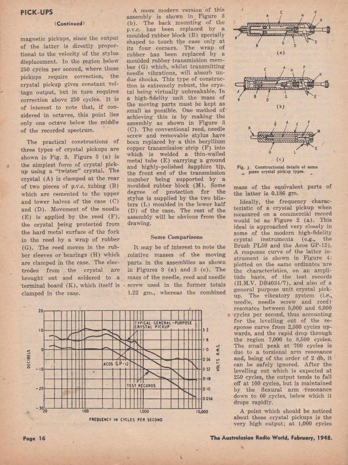
The practical constructions of three types of crystal pickups are shown in F ig. 3. Figure 3 (a) is the simplest form of crystal pickup using a “tw ister” crystal. The crystal (A ) is clamped at the rear of two pieces of p.v.c. tubing (B ) which are cemented to the upper and lower halves of the case (C) and (D ). Movement of the needle (E ) is applied by the reed (F ) , the crystal being protected from the hard metal surface of the fork in the reed by a wrap of rubber (G ). The reed moves in the rubber sleeves or bearings (H ) which are clamped in the case. The electrodes from the crystal are brought out and soldered to a terminal board (K ), which itself is clamped in the caae.
A more modern version of this assembly is shown in Figure 3 (b). The back mounting of the p.v.c. has been replaced by a moulded rubber block (B ) specially shaped to touch the case only at its four corners. The wrap of rubber has been replaced by a moulded rubber transmission member (G) which, whilst transm itting needle vibrations, will absorb undue shocks. This type of construction is extremely robust, the crystal being virtually unbreakable. In a high-fidelity unit the mass of the moving parts must be kept as small as possible. One method of achieving this is by making the assembly as shown in Figure 3(C ). The conventional reed, needle screw and removable stylus have been replaced by a thin beryllium copper transmission strip (F ) into which is welded a thin-walled metal tube (E ) carrying a ground and highly-polished sapphire tip, the front end of the transmission member being supported by a moulded rubber block (M ). Some degree of protection for the stylus is supplied by the two blisters (L ) moulded in the lower half(D ) of the case. The rest of the assembly will be obvious from the drawing.
Some Comparisons
I t may be of interest to note the relative masses of the moving parts in the assemblies as shown in Figures 3 (a ) and .3 (c ) . The mass of the needle, reed and needle screw used in the form er totals1.2.2 gm., whereas the combined
Fig. 3. Constructional details of some ̂ piezo crystal pickup types.
mass of the equivalent parts of the la tter is 0.186 gm.
Ideally, the frequency characteristic of a crystal pickup when measured on a commercial record would be as Figure 2 (a ) . This ideal is approached very closely in some of the modern high-fidelity crystal instruments (e.g., the Brush PL50 and the Acos GP-12).. A response curve of the latter instrument is shown in Figure 4: plotted on the same ordinates are the characteristics, on an amplitude basis, of the test records (H.M.V. DB4034/7), and also of a general purpose unit crystal pickup. The vibratory system (i.e., needle, needle screw and reed) resonates between 5,000 and 6,000 cycles per second, thus accounting for the levelling out of the response curve from 2,500 cycles upwards, and the rapid drop through the region 7,000 to 8,500 cycles. The small peak a t 700 cycles is due to a torsional arm resonance and, being of the order of 2 db, it can be safely ignored. A fter the levelling out which is expected at 250 cycles, the output tends to fall off a t 100 cycles, but is maintained by the flexural arm resonance down to 60 cycles, below which it drops rapidly.
A point which should be noticed about these crystal pickups is the very high output; a t 1,000 cycles
Page 16 The Australasian Radio World, February, 1948.

'i t is .7 volt fo r the high fidelity unit and 1.0 volt fo r the general- purpose unit; at 250 cycles it is2.5 volts and 3.2 volts respectively.
These response curves show that to obtain faithful reproduction there is a need for a levelling of the output to produce a linear input to the amplifier grid.
The general-purpose instrument is often used without any correction at all, since the fall in top will appear to reduce needle scratch, and will minimise the unpleasantness of “pentode top” so often associated with the less expensive and older radio receivers. Should some degree of top correction be required, the simple circuit shown in Figure 5 will be found completely satisfactory.
For those requiring an extremely high standard of reproduction, the high-fidelity instrument (Acos GP-12) with full equalisation will be chosen. Though simple, equalisation should be a m atter of some care; tuned circuits and iron-cored components should obviously be avoided. The simple circuit shown in Figure 6
o sMn - v w w *f v'WW*- •
0 00lp.filMfi
AHPUFICHiHPin
Suggested correction circuit for ordinary crystal pick-ups.
is recommended, and a response. curve of the high-fidelity pickup using this equaliser is shown in Figure 7. I t will be seen from this that the overall output level has dropped to 0.1 volt, which is, of course, what would be expected.
I t is often stated that the overriding disadvantage of crystal pickups is that they introduce
VOLUME CONTROL
Fie 6 C ircuit giving full equalization with - * Acos GP-X2 high-fidelity pickup.
-10
-20
- 5020 100 1,000 FREQUENCY IN CYCLES PER SECOND
0 5#
0-52
018
010
0-0 M
10,000
Ferequency response of the h igh-fide lity type of crystal pick-up when used with equalisation, as shown in figure 6.
severe harmonic distortion. The authors have taken many cathode ray oscillographs over a wide fre quency range, and have come to the conclusion that with a well- designed (though not necessarily expensive) crystal pickup, the wave-form distortion is negligible, being well under the limit of 2 per cent, accepted by the industry for high-fidelity apparatus. Much harmonic distortion is introduced in the first amplifier stage, where the high output from the pickup over
loads the input valve. This trouble will not be encountered if the input circuits (Figures 5 and 6) recommended above are used.
The piezo-electric crystal is inherently capable of the highest fidelity of reproduction, and when housed in pickup cartridges of modern lightweight design will prove by its performance that it is worthy of the serious consideration of quality enthusiasts.
— “Wireless World,” London.
SAVE MONEY WITH A
s i m nOrder Yours To-DayMake sure you get every issue as soon as it is published. Place an order w ith your newsagent or send direct to us for a
subscription.IT SAVES YOU MONEY!IT SAVES YOU TIME!
We guarantee tha t every subsciber has his copy posted the same day it conies o ff the
press.• • __________
Enclosed please find remittance for 1 0 /6 in payment fo r an annual subscription to the "Australasian Radio W orld ," commencing with the.......................issue.
NAME .................................................................................................................................STREET and NUMBER ...................................................................................................2 ITY ...............................................................................STATE.................................
RATES6 issues 5 /3
+ 12 issues 10 /6 * 24 issues 2 0 /—
POST FREE
AUSTRALASIAN RADIO WORLD Balcombe Street Mornington
Victoria
The Australasian Radio W orld, February, 1948. Page 17
HINTS AND TIPSBy PAUL STEVENS
Capacity Aerial
Many modern sets, mostly small mantels, feature this type of “inbuilt” aerial, which, on the circuit diagram, looks ju st like an ordinary condenser connected between one side of the power line and the aerial terminal. I f you tried this on your set you will probably find it to be a sad failure. The reason is that fo r this type of aerial a low impedance input coil has to be used, as with the standard high impedance type the shunt capacity of the power transform er acts like a dead short. Fig. 2 shows the simple circuit. As there are no
low impedance input coils on the m arket, we can simply adapt one for our purposes by winding a few turns of wire, between 8 and 20 (you have to try fo r best results), closely around the cold end of the grid coil. Connect one end to earth, the other via a .01 or .02 condenser to one side of the power line. The coupling condenser must be of good quality and a t least 2000V test. The power line thus acts as an aerial, the chassis of the set as counterpoise. An iron cored coil must be used to enable the resetting of the coil inductance, which will be upset by the process. The high impedance input coil remains unused. This type of aerial should only be' used on carry-around midgets, as it is inherently more noisy than any other type as fa r as man-made static is Concerned. The small counterpoise, the set itself, also limits its efficiency; but in a quiet location and for local reception it is certainly a good thing.
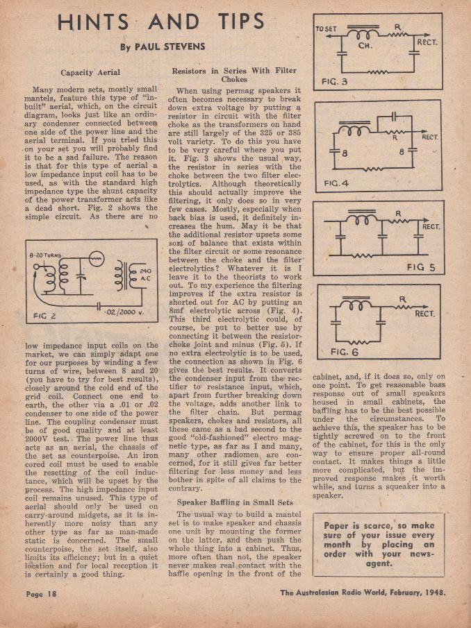
Resistors in Series W ith Filter Chokes
When using permag speakers it often becomes necessary to break down extra voltage by putting a resistor in circuit with the filter choke as the transform ers on hand are still largely of the 325 or 385 volt variety. To do this you have to be very careful where you put it. F ig . 3 shows the usual way, the resistor in series with the choke between the two filter elec- trolytics. Although theoretically this should actually improve the filtering, it only does so in very few cases. Mostly, especially when back bias is used, i t definitely increases the hum. May it be that the additional resistor upsets some sort of balance that exists within the filter circuit or some resonance between the choke and the filter electrolytics ? W hatever it is I leave it to the theorists to work out. To my experience the filtering improves if the extra resistor is shorted out fo r AC by putting an 8mf electrolytic across (F ig . 4 ). This third electrolytic could, of course, be put to better use by connecting it between the resistor- choke jo int and minus (F ig . 5 ) . I f no extra electrolytic is to be used, the connection as shown in F ig . 6 gives the best results. I t converts the condenser input from the rectifier to resistance input, which, apart from further breaking down the voltage, adds another link to the filter chain. But permag speakers, chokes and resistors, all these came as a bad second to the good “old-fashioned” electro magnetic type, as fa r as I and many, many other radiomen are concerned, for i t still gives fa r better filtering fo r less money and less bother in spite of all claims to the contrary.
Speaker Baffling in Small SetsThe usual way to build a mantel
set is to make speaker and chassis one unit by mounting the form er on the latter, and then push the whole thing into a cabinet. Thus, more often than not, the speaker never makes real contact with the baffle opening in the front of the
- |----------I I----
0 R E C T .
= 8 8 =
F I G . 4
cabinet, and, i f i t does so, only on one point. To get reasonable bass response out of small speakers housed in small cabinets, the baffling has to be the best possible under the circumstances. To achieve this, the speaker has to be tightly screwed on to the front of the cabinet, fo r this is the only way to ensure proper all-round contact. I t makes things a little more complicated, but the improved response makes it worth while, and turns a squeaker into a speaker.
Paper is scarce, so make sure of your issue every month by placing an order with your news
agent.
Page 18 The Australasian Radio World, February, 1948.
HOW T O M A K E :—
HOME-WOUND POWER TRANSFORMERS
A POW ER transform er is a piece of equipment by means of which alternating current may be changed from one
voltage to another and consists essentially of a laminated steel core, a primary winding which is generally tapped for connection to supply mains of various voltages, secondary windings for supplying high tension and filament voltages and the insulation between these components.
The Laminations
The core which is made of thin laminations of special steel (generally silicon steel) acts as a closed magnetic circuit around which the coil windings are formed. If a primary is wound around the core and connected to an a.c. line of suitable voltage, current will flow in this coil and magnetise the core. This current is known as the exciting current.
The magnetic flux produced by the exciting current will be of an alternating nature and any turn of wire surrounding the core will have a voltage induced in it by this varying flux. I f a second coil (called the secondary) is also wound around the core, it will have
a voltage induced in it by the alternating flux produced by the current passing through the primary. The magnitude of the secondary voltage will be proportional to the number of turns on it and inversely proportional to the number of turns on the primary.
When the primary of a transform er is connected to a suitablea.c. supply, the magnetic flux produced, which may be referred to as increasing and decreasing lines of
By
J. G. DuFAUR
magnetic force in the core, cuts the primary windings twice for every cycle of supply frequency; the flux produces a back voltage in the primary (commonly known as back e.m.f.) which is in direct opposition to the supply voltage.
Core Losses I f the core is made from high
quality steel which has only small losses induced in it by the fluc-
In the recent scramble for back numbers, the greatest demand was for the January, 1945 issue, w ith the article on winding power transformers. A t the request of dozens who were unable to get the back number, we are reprinting the article in
fu ll.
tuating magnetisation effect, the back e.m.f. wTill be almost equal and opposite to the primary applied voltage and thus the current passing through the primary winding will be proportional to the difference of these two voltages. The magnetising current therefore is generally small because in a properly designed transform er little difference exists between the two abovementioned voltages. In the same way as the back e.m.f. is generated in the primary coil, an e.m.f. is also induced in the secondary coil, since it is also cut by the flux established by the primary.
No current can flow in the secondary unless a load such as a resistance is placed across its te rminals. When a load is applied,
(Continued on next page)
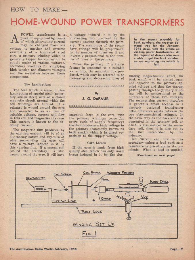
E v e S c r e w . W o o d e n F o r m c bRfcV. XTOuHTEft.
mrm
Ha n o D r iu .
F l e x i b l e . L e a d
"Fa b l c E d g e .
W i n d i n g S e t U p .
F i g . I
The Australasian Radio World, February, 1948. Page 19
TRANSFORMERS( C o n t in u e d )
current flows through the secondary winding and sets up a further flex which is opposite to that produced by the primary. This causes an overall reduction of flux in the core and thus the amount of current flowing in the primary increases to restore the original flux density caused by the magnetising current. I t can therefore be seen that the greater the current drawn from the secondary winding, the greater will be the current which flows in the primary.
Steel cores will only carry a limited amount of magnetic flux and if the flux density is increased beyond a certain point, saturation occurs. W ith this condition, the core is conducting all the flux it is able to carry and the number of magnetic lines of force cannot be fu rther increased.
Various losses occur in all transformers— these are of three main types— eddy current, copper and hysterisis losses.
Reason for Lamination
Eddy current losses appear as heat in the steel core and are caused by magnetic lines of flux cutting the core and producing currents in it as the core tends to act as a short-circuited coil of one turn. These currents flowing through the core dissipate energy in the form of heat. For this reason, transform er cores cannot be made of solid material, but are laminated, each lamination being insulated from the next, either by an oxidised film, or a coat of varnish. This makes the resistance of the core to electric currents generated by the flux very high and thus limits the amount of power dissipated.
Copper losses within a transformer also appear in the form of heat and are simply caused by the current flowing through the resistance of the windings.
These losses are, in both cases, the product of the current in amperes squared, multiplied by the resistance concerned in ohms and are measured in watts. To minimise copper losses, it is necessary that the length of windings be as small as possible and that the
wires used be as large in cross section as practicable so as to minimise the resistance.
Hysterisis losses in the core re sult from the fact that energy is required to carry iron or steel through cycles of magnetisation. They may be minimised by a careful selection of the type of m aterial used for the fabrication of the core.
Obtaining Material
As it is now difficult fo r set builders to obtain power transformers, it is proposed to give practical details of how to make these components at home. The process is a rather long and tedious one, but very efficient units can be accomplished if sufficient time and care is taken.
The first m atter fo r consideration is where to obtain the necessary wire, laminations and insulation.
Secondhand wire is generally not difficult to procure, as most radio shops can supply limited quantities, either enamel or cotton insulated. The main difficulty is that shops are often unable to tell the
buyer the accurate gauge of the scrap wire they have to sell and it is therefore advisable, if possible, to borrow a micrometer and take this along with you when the purchase is made. Details of the diameter of all S.W.G. and B. & S. gauges of wire can be obtained from practically any electrical or radio handbook.
Using Secondhand Wire
Much secondhand enamel-covered wire available a t present has the insulation badly chipped and the enamel has flakes off in various places. This wire is very unsatis-
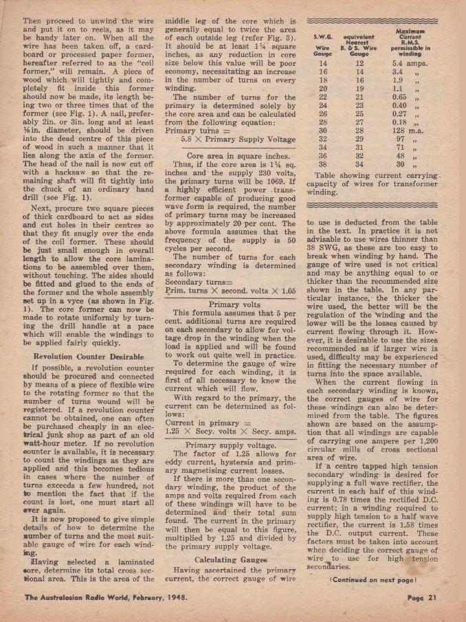
L tH tN A T C D STEEL COPfL.
C P * g AtKCA » A 'x f l* Jq i n
factory fo r winding transform ers, in fact, if a short circuit occurs between two adjacent turns, the unit will overheat and be quite useless in practice. Therefore, when buying enamel-covered wire, make sure that the insulation is in good condition. Cotton and silk covered wires, if obtainable, are less susceptible to this trouble, but as their covering is considerably thicker than enamel, difficulty may be experienced in putting the required number of turns around the core in the space available.
Salvage Cores
Laminations may be easily obtained by purchasing a burnt-out power transform er — these are readily available from secondhand wireless shops at a small cost. I f you are able to procure a transformer in which the primary winding is intact, this will be an advantage; in this case only new secondary windings need be provided, as in practically all cases the primary is closest to the core. However, since windings on commercial transform ers are all put on by machinery, difficulty is always experienced in replacing as many turns as can be taken off. For this reason, it is advisable to purchase a core which is considerably larger than the type used in a commercially built transform er of the size and specification which it is desired to make.
Let us assume that a burnt-out unit has been procured and that, as is generally the case, its primary winding is broken, thus rendering the whole unit useless. In this case, the laminations should be taken out and put on one side.
Page 20 The Australasian Radio World, February, 1948.
Then proceed to unwind the wire and put it on to reels, as it may be handy later on. When all the wire has been taken off, a cardboard or processed paper former, hereafter referred to as the “coil form er,” will remain. A piece of wood which will tightly and completely fit inside this former should now be made, its length being two or three times that of the form er (see Fig. 1). A nail, preferably 2in. or 3in. long and at least %in. diameter, should be driven into the dead centre of this piece of wood in such a manner that it lies along the axis of the former. The head of the nail is now cut off with a hacksaw so that the remaining shaft will fit tightly into the chuck of an ordinary hand drill (see F ig. 1).
Next, procure two square pieces of thick cardboard to act as sides and cut holes in their centres so that they fit snugly over the ends of the coil former. These should be ju st small enough in overall length to allow the core laminations to be assembled over them, without touching. The sides should be fitted and glued to the ends of the form er and the whole assembly set up in a vyce (as shown in Fig. 1). The core form er can now be made to rotate uniformly by turning the drill handle at a pace which will enable the windings to be applied fairly quickly.
Revolution Counter DesirableI f possible, a revolution counter
should be procured and connected by means of a piece of flexible wire to the rotating former so that the number of turns wound will be registered. I f a revolution counter cannot be obtained, one can often be purchased cheaply in an electrical junk shop as part of an old watt-hour meter. I f no revolution counter is available, it is necessary to count the windings as they are applied and this becomes tedious in cases where the number of turns exceeds a few hundred, not to mention the fa ct that if the count is lost, one must start all •Ter again.
I t is now proposed to give simple details of how to determine the som ber of turns and the most suitable gauge of wire for each winding-
Having selected a laminated •ore, determine its total cross sectional area. This is the area of the
middle leg of the core which is generally equal to twice the area of each outside leg (refer Fig. 3). I t should be a t least 1% square inches, as any reduction in core size below this value will be poor economy, necessitating an increase in the number of turns on every winding.
The number of turns for the primary is determined solely by the core area and can be calculated from the following equation: Prim ary turns =
5.8 X Prim ary Supply Voltage
Core area in square inches.Thus, if the core area is 1% sq.
inches and the supply 230 volts, the primary turns will be 1069. I f a highly efficient power transformer capable of producing good wave form is required, the number of primary turns may be increased by approximately 20 per cent. The above formula assumes that the frequency of the supply is 50 cycles per second.
The number of turns for each secondary winding is determined as follows:Secondary tu rns=Prim, turns X second, volts X 1.05
Prim ary voltsThis formula assumes that 5 per
cent, additional turns are required on each secondary to allow for voltage drop in the winding when the load is applied and will be found to work out quite well in practice.
To determine the gauge of wire required for each winding, it is first of all necessary to know the current which will flow.
With regard to the primary, the current can be determined as fo llows:Current in primary =1.25 X Secy, volts X Secy. amps.
Prim ary supply voltage.The factor of 1.25 allows for
eddy current, hystersis and primary magnetising current losses.
I f there is more than one secondary winding, the product of the amps and volts required from each of these windings will have to be determined and their total sum found. The current in the primary will then be equal to this figure, multiplied by 1.25 and divided by the primary supply voltage.
Calculating GaugesHaving ascertained the primary
current, the correct gauge of wire
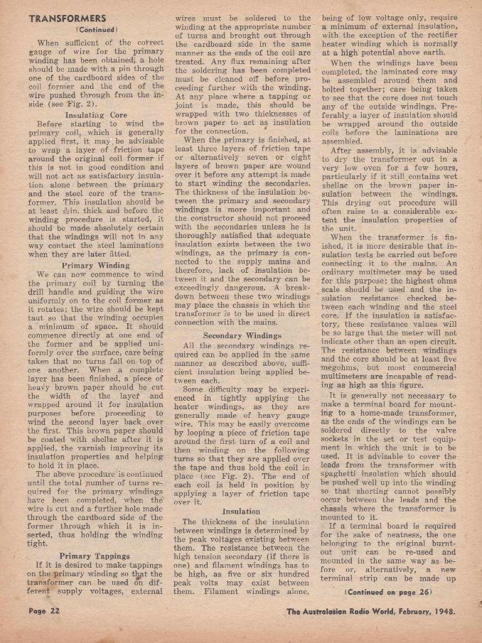
S.W.G. equ iva len tM axim um
CurrentNearest R.M.S.
W ire B. & S. W ire permissible inGouge Gauge w inding
14 12 5.4 amps.16 14 3.4 „18 16 1.9 „20 19 1.1 „22 21 0.65 „24 23 0.40 „26 25 0.27 „28 27 0.18 „30 28 128 m.a.32 29 97 „34 31 71 „36 32 48 „38 34 30 „
Table showing current carryircapacity of wires for transform er winding.
to use is deducted from the table in the text. In practice it is not advisable to use wires thinner than 38 SWG, as these are too easy to break when winding by hand. The gauge of wire used is not critical and may be anything equal to or thicker than the recommended size shown in the table. In any particular instance, the thicker the wire used, the better will be the regulation of the 'Winding and the lower will be the losses caused by current flowing through it. However, it is desirable to use the sizes recommended as if larger wire is used, difficulty may be experienced in fitting the necessary number of turns into the space available.
When the current flowing in each secondary winding is known, the correct gauges of wire for these windings can also be determined from the table. The figures shown are based on the assumption that all windings are capable of carrying one ampere per 1,200 circular mills of cross sectional area of wire.
I f a centre tapped high tension secondary winding is desired for supplying a full wave rectifier, the current in each half of this winding is 0.78 times the rectified D.C. current; in a winding required to supply high tension to a half wave rectifier, the current is 1.58 times the D.C. output current. These factors must be taken into account when deciding the correct gauge of wire to use for high tension secondaries.
(Continued on next page)
The Australasion Radio World, February, 1948. Page 21
TRANSFORMERS(Continued)
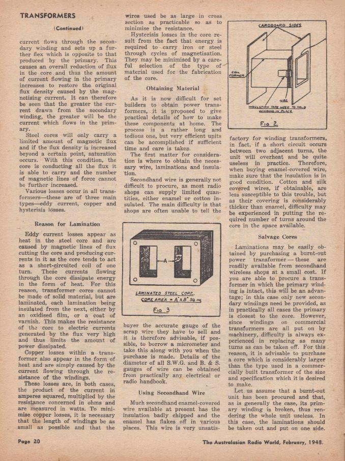
When sufficient of the cotrect gauge of wire for the primary winding has been obtained, a hole should be made with a pin through one of the cardboard sides of the coil form er and the end of the wire pushed through from the inside (see Fig. 2).
Insulating CoreBefore starting to wind the
primary coil, which is generally applied first, it may be advisable to wrap a layer of friction tape around the original coil form er if this is not in good condition and will not act as satisfactory insulation alone between the primary and the steel core of the transformer. This insulation should be a t least # 2 in. thick and before the winding procedure is started, it should be made absolutely certain that the windings will not in any way contact the steel laminations when they are later fitted.
Prim ary WindingWe can now commence to wind
the primary coil by turning the drill handle and guiding the wire uniformly on to the coil form er as it rotates; the wire should be kept taut so that the winding occupies a minimum of space. It should commence directly at one end of the form er and be applied uniformly over the surface, care being taken that no turns fall on top of one another. When a complete layer has been finished, a piece of heavy brown paper should be cut the width of the layef and wrapped around it for insulation purposes before proceeding to wind the second layer back over the first. This brown paper should be coated with shellac after it is applied, the varnish improving its insulation properties and helping to hold it in place.
The above procedure is continued until the total number of turns required for the primary windings have been completed, when the' wire is cut and a further hole made through the cardboard side of the form er through which it is inserted, thus holding the winding tight.
Prim ary TappingsIf it is desired to make tappings
on the primary winding so tljpt the transform er can be used on different supply voltages, external
wires must be soldered to the winding at the appropriate number of turns and brought out through the cardboard side in the same manner as the ends of the coil are treated. Any flux remaining after the soldering has been completed must be cleaned off before proceeding further with the winding. At any place where a tapping or joint is made, this should be wrapped with two thicknesses of brown paper to act as insulation for the connection. *
When the primary is finished, at least three layers of friction tape or alternatively seven or eight layers of brown paper are wound over it before any attempt is made to start winding the secondaries. The thickness of the insulation between the primary and secondary windings is more important and the constructor should not proceed with the secondaries unless he is thoroughly satisfied that adequate insulation exists between the two windings, as the primary is connected to the supply mains and therefore, lack of insulation between it and the secondary can be exceedingly dangerous. A breakdown between these two windings may place the chassis in which the transform er is to be used in direct connection with the mains.
Secondary WindingsAll the secondary windings re
quired can be applied in the same manner as described above, sufficient insulation being applied between each.
Some difficulty may be experienced in tightly applying the heater windings, as they are generally made of heavy gauge wire. This may be easily overcome by looping a piece of friction tape around the first turn of a coil and then winding on the following turns so that they are applied over the tape and thus hold the coil in place (see F ig. 2 ). The end of each coil is held in position by applying a layer of friction tape over it.
InsulationThe thickness of the insulation
between windings is determined by the peak voltages existing between them. The resistance between the high tension secondary (if there is one) and filament windings has to be high, as five or six hundred peak volts may exist between them. Filam ent windings alone,
being of low voltage only, require a minimum of external insulation, with the exception of the rectifier heater winding which is normally at a high potential above earth.
When the windings have been completed, the laminated core may be assembled around them and bolted together; care being taken to see that the core does not touch any of the outside windings. Preferably a layer of insulation should be wrapped around the outside coils before the laminations are assembled.
A fter assembly, it is advisable to dry the transform er out in a very low oven for a few hours, particularly if it still contains wet shellac on the brown paper insulation between the windings. This drying out procedure will often raise to a considerable extent the insulation properties of the unit.
When the transform er is finished, it is more desirable that insulation tests be carried out before connecting it to the mains. An ordinary multimeter may be used for this purpose; the highest ohms scale should be used and the insulation resistance checked between each winding and the steel core. I f the insulation is satisfactory, these resistance values will be so large that the meter will not indicate other than an open circuit. The resistance between windings and the core should be at least five megohms, but most commercial multimeters are incapable of reading as high as this figure.
It is generally not necessary to make a terminal board for mounting to a home-made transformer, as the ends of the windings can be soldered directly to the valve sockets in the set or test equipment in which the unit is to be used. It is advisable to cover the leads from the transform er with spaghetti insulation which should be pushed well up into the winding so that shorting cannot possibly occur between the leads and the chassis where the transform er is mounted to it.
If a terminal board is required for the sake of neatness, the one belonging to the original burnt- out unit can be re-used and mounted in the same wTay as before or, alternatively, a new terminal strip can be made up
(Continued on page 26)
Page 22 The Australasian Radio World, February, 1948.
f RETAIL PRICE \ in o il C ap ito l C ities
£ l 6 /l 7 /6(Inc lud ing Valves and
Batteries) A ttra c tiv e D iscount
^ to Trade and i V Am ateurs f
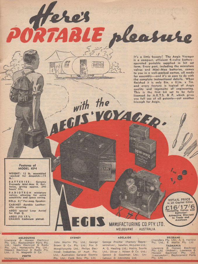
P O R T A B L E a & a U m.uIt's a little "beauty! The Aegis Voyager is a compact, efficient 4-valve battery- operated portable supplied in k it set form. Every part, including the miniature valves and M in i-M ax batteries, comes to you in a well-packed carton, all ready for assembly— and it's so easy to do with the complete instructional details. When finished it is only 8in. x 6Jin. x 7in. and every feature is typical of Aegis quality and ingenuity of engineering. This is the firs t k it set to be fu lly licensed by A.R.T.S. & P. which gives you fu ll use of all patents— yet another triumph for Aegis.
Features of MODEL KP4
W EIG HT: 12 lb. assembled (packed fo r despatch— 14lb .) .B A T T E R I E S : Genuine Eveready M in i-M a x B. B a tteries, g iv ing approx. 240 hours' life .R A D I O T R O N m in ia tu re valves, a llow ing fo r extra sens itiv ity and space saving. ROLA 3i " Per-mag. Speaker.CABINET durable Leathere tte covering.AEGIS special Loop A e ria l fo r H igh Q.AEGIS J10 I.F /s.CHASSIS Cadmium plated. ECIS MANUFACTURING CO.PTY. LTD.
MELBOURNE • AUSTRALIA
MELBOURNELawrence & Hanson Electrical Pty. L td .; Replacement Parts Pty. L td .; Vealls Electrical & Radio Pty. L td .; Hom ecrafts Pty. L td.; Howard Electrical & Radio Pty. L td .; J. H. M agra th & Co.
PERTHNicholsons Ltd._____________________
SYDNEY
John M a rtin Pty. L td .; George Brown & Co. Pty. L td .; Fox & M acgillycuddy L td .; Philips Electr ica l Industries o f Aust. Pty. L td .; A ustra lian General Electric Pty. L td .; Cook Bros. Pty. Ltd.
ADELAIDE
George Proctor (Factory Represe n ta tive ); Newton, M cLaren L td.; A. G. Healing L td .; Harris, Scarfe L td .; O liver J. N ilsen & Co. L td .; Gerard & Goodman L td .; Un- behaun & Johnstone Ltd.
BRISBANEChandlers Pty. L td .; A. E. H arrold Pty. L td .; B. M a rtin Pty. Ltd.
TA S M A N IA Lawrence & Hanson Electrical Pty. Ltd. (H o b a rt) ; Lawrence & Hanson Electrical Pty. Ltd. (Launceston); Replacement Parts Pty. Ltd.
CONVERTERS FOR "SIX" AND "TEN"Interesting English Circuits with 3 Me. I.F.
I
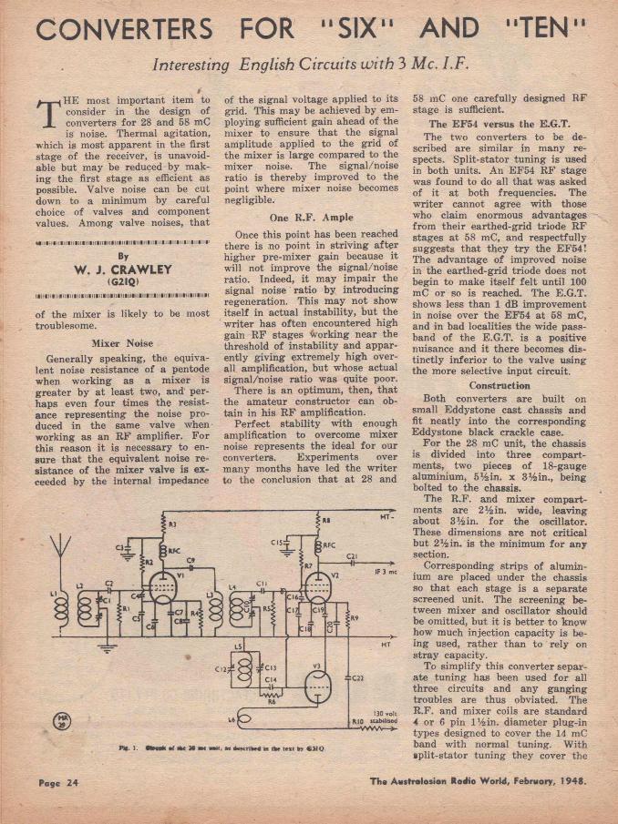
THE most important item to consider in the design of converters for 28 and 58 mC is noise. Thermal agitation,
which is most apparent in the first stage of the receiver, is unavoidable but may be reduced by making the first stage as efficient as possible. Valve noise can be cut down to a minimum by careful choice of valves and component values. Among valve noises, that
ByW. J. CRAW LEY
(G2IQ)l l l l i l l l l H l l l l l l l l l l H l l l l l l l l l l l l f l l l W l l t t l l l l l l l H H I l H t H l l l i l W
of the mixer is likely to be most troublesome.
Mixer NoiseGenerally speaking, the equiva
lent noise resistance of a pentode when working as a m ixer is greater by a t least two, and perhaps even four times the resistance representing the noise produced in the same valve when working as an R F amplifier. For this reason it is necessary to ensure that the equivalent noise resistance of the mixer valve is exceeded by the internal impedance
of the signal voltage applied to its grid. This may be achieved by employing sufficient gain ahead of the mixer to ensure that the signal amplitude applied to the grid of the mixer is large compared to the mixer noise. The signal/noise ratio is thereby improved to the point where m ixer noise becomes negligible.
One R .F . Ample
Once this point has been reached there is no point in striving after higher pre-m ixer gain because it will not improve the signal/noise ratio. Indeed, it may impair the signal noise ratio by introducing regeneration. This may not show itself in actual instability, but the writer has often encountered high gain R F stages working near the threshold of instability and apparently giving extremely high overall amplification, but whose actual signal/noise ratio was quite poor.
There is an optimum, then, that the amateur constructor can obtain in his R F amplification.
Perfect stability with enough amplification to overcome mixer noise represents the ideal for our converters. Experiments over many months have led the writer to the conclusion that at 28 and
58 mC one carefully designed R F stage is sufficient.
The E F54 versus the E.G.T.The two converters to be de
scribed are sim ilar in many respects. Split-stator tuning is used in both units. An EF54 R F stage was found to do all that was asked of it at both frequencies. The writer cannot agree with those who claim enormous advantages from their earthed-grid triode R F stages at 58 mC, and respectfully suggests that they try the E F 54 ! The advantage of improved noise in the earthed-grid triode does not begin to make itself fe lt until 100 mC or so is reached. The E.G.T. shows less than 1 dB improvement in noise over the E F54 at 58 mC, and in bad localities the wide pass- band of the E.G.T. is a positive nuisance and it there becomes distinctly inferior to the valve using the more selective input circuit.
ConstructionBoth converters are built on
small Eddystone cast chassis and fit neatly into the corresponding Eddystone black crackle case.
For the 28 mC unit, the chassis is divided into three compartments, two pieces of 18-gauge aluminium, 5% in. x 3% in., being bolted to the chassis.
The R .F . and m ixer compartments are 2% in. wide, leaving about 3% in. for the oscillator. These dimensions are not critical but 2% in. is the minimum fo r any section.
Corresponding strips of aluminium are placed under the chassis so that each stage is a separate screened unit. The screening between mixer and oscillator should be omitted, but it is better to know how much injection capacity is being used, rather than to rely on stray capacity.
To simplify this converter separate tuning has been used for all three circuits and any ganging troubles are thus obviated. The R .F . and mixer coils are standard4 or 6 pin l% in . diameter plug-in types designed to cover the 14 mC band with normal tuning. With »plit-stator tuning they cover the
n t . 1 . I M • H h X M m i l . * * f e x r I M In I k t I n i k> ( H O
Poge 24 Th» Australasian Radio World, February, 1948.

Ft*. 2. Tbe 5$ me converter clrcoit.
28-30 mC band quite easily. The size of these coils clearly indicates the advantage of increased coil inductance which split-stator tuning affords. The grid winding consists of 7 turns of 24 or 26 gauge SWG enamelled copper wire, but the aerial winding is a m atter fo r experiment. The w riter uses a balanced input with 300-ohm Amphenol line, and three turns have been found optimum for this condition. A 70-ohm line requires 2 turns. The split-stator condensers may be any design provided that the physical dimensions allow for mounting in the restricted space available. The writer uses an Eddystone 25 x 25 mmf. for the R .F . and a Polar 2-gang 25 mmf. condenser for the mixer. The oscillator coil is tuned roughly by a 50 mmf. midget air-dielectric type, whilst another 50 mmf., with all rotor plates but one removed, serves for bandspread. This capacity (about 10 mmf.) is sufficient to spread 28 to 30 mC/s over most of the 0 to 100 dial.
Points To WatchSpecial points to note in wiring
the converter are as follows: Keep all plate and grid leads as short and as rigid as possible. Where grid leads have to go through the chassis to the variable condensers, use either ceramic feed-through bushes or sheath the wire in polythene tube or sim ilar low-loss in- sulant. Avoid all loops by having one common earth point for each stage. The best position for this is a t the screw holding the valve holder in place and may be made by bolting three soldering tags to this screw and fanning them out for easy access. There are four cathode outlets to the E F 54 ; bypass each tag separately to earth with a 500 mmf. mica condenser. I f possible arrange one of these condensers to lie right across the valve holder so that it acts as fu rther screening between grid and plate.
Mixer noise is reduced by the use of high-value cathode and screen resistors. In the interests o f high conversion gain, high signal/noise ratio and low signal- grid current, single grid input is used in the mixer. This results in some pulling, but its advantages outweigh this one disadvantage. The use of a very small capacity reduces pulling to a minimum, and
this capacity is obtained by wrapping a piece of insulated wire once around the mixer grid pin and connecting the other end to the oscillator grid. The choice of oscillator valve is not critical and the following types have been used with good results: 6C4, 9001, 9002, 9003, 6AG5, 6AK5, 6J6, all triode- connected. The photograph shows a 6AG5, triode-connected, in this position.
Operation
The writer uses an output fre quency of 3 mC which means tuning the oscillator through 31/33 mC or 25/27 mC. With the oscillator coil specified, which has three turns for the grid winding and one turn tightly coupled for the reaction winding on a Denco standard former, the setting of the 50 mmf. oscillator condenser is about half-way in. I f no wavemeter is available, finding the band is a m atter of trial and error. The writer prefers to tune the oscillator through 31/33 mC and resonance in C l and CIO is indicated by a sharp increase in background hiss.
The 58 mC Converter
The circuit of this unit is similar in most respects to the 28 mC set. The 6AK5 has been found an excellent mixer for this frequency and a 6J6 strapped as one triode, in which condition its mutual conductance is 10 mA/volt, is a strong and stable oscillator.
The coils, which in the case of the R F and mixer stages are mounted as near to the tuning condenser as possible, are self- supporting, wound with 16 SWG enamelled or silvered wire. The R F coil has six turns lin . diameter whilst the m ixer is made slightly smaller, namely 6 turns ysin. diameter. The reason for this is to dispense with the trimmer across the R F coil, and one trimmer only, that in the mixer circuit, is used. For the oscillator, where stability is the main consideration, three turns on a circular piece of dis- trene, % in. diameter, with one turn for reaction, are used. This coil is tuned by a Philips 30 mmf ceramic trimmer and a 4 mmf parallel condenser spreads the band about 70° on the 0/100° dial.
The ganged condenser used in the R F and mixer stages is a standard twin-gang unit, each section of which has been sawn into two parts with a thin hacksaw blade. The unit is thus converted into two split-stators, ganged. No aerial coupling winding is shown, as here again experiment with different sizes will pay dividends in the transfer of energy. As a guide, one turn is the optimum for a 70-ohm line.
The precautions taken in the construction of the 28 mC unit are duplicated in this set. The chassis is divided into two parts by a screen 5% in. wide and 3% in. deep.
(Continued on pags 26)
T in Australasian Radio World, February, 1948. Page 25
CONVERTER(Continued)
A further screen 4 Uin. wide divides the R F and mixer. A small aperture lV2 in. X l% in . is cut out of this screen so that it fits over the twin condenser. The coils ar§ mounted on small ceramic terminal blocks, that fo r the R F grid being directly above the tuning condenser and that of the mixer alongside the 6AK5.
The remarks on operation hold good for both units. For an output frequency of 3 mC, the oscillator trimmer should be two-thirds out. Resonance of R F and mixer is again indicated by an increase in hiss, but the mixer trimmer must be adjusted whilst swinging the gang through resonance.
The writer is a poor mechanic and has no doubt that many readers will be able to make fa r better looking converters than he has done. But it is hoped that the description of these units will
TRANSFORMERS(Continued from page 22)
from a piece of thin bakelite with soldering lugs riveted to it at appropriate distances around the edge.
Not for Audios A word of warning! Do not
imagine it is easy to wind a satisfactory audio transform er merely using the data given in this article. Good audio transform ers are very difficult things to make and precise details of the permeability and flux density of the core material under various conditions are necessary before a satisfactory unit can even be designed.
Once again, as the wire used in
serve as a guide to those who are striving for performance a little better than the average.
— “Shortwave Magazine,” England.
■ .■ .■ .v .v .’ .v .v .v .v .v .v .v .v ,
NEW ZEALANDERS!The quickest and simplest way
of subscribing to the"AUSTRALASIAN RADIO WORLD"
is to get in touch with H. BARNES & CO.4 Boulcott Terrace
WellingtonSUBSCRIPTION: 1 0 /6 Per AnnumThey will arrange all the details and give you prompt and courteous attention.
DO IT NOW!V .V / .V .V .V / .W ^ A V .W V .these units is generally very fine and many thousands of turns are required, they are horrible things to attempt to make by hand. Practically any radio shop is able to supply new or second-hand audio transform ers for a few shillings, which will probably be much more satisfactory than a home-made unit.
HEM-FEBRUARY SUGGESTIONS
From the SPECIAL AMATEUR DIVISIONSteanes "D ynam ax" Moving Coil Microphone. Designed for quality speech operation, 50 ohm type £ 5 /1 7 /6 ; Grid Type £ 7 /5 / - .
University Meters as illustrated above, 0—1 M illiammeter type F3 £ 2 /1 2 /6 ; plus sales tax. Full range all types carried in stock. Special requirements to order.
E.M.A. Flexible Drives—complete with knob and panel bush for shaft — length 4 " 2 /8 ea. 6 " 2 /11 each. 8 " 3 /3 ea., nett plus Sales Tax.
• "R o la " Permag loudspeakers now available for K it Set builders.
• A ll types of measuring instruments skilfu lly repaired— Prompt service.
J.H. MAG RATH & Co.36884414208 LT. L O N S D A L E ST., f T l ELBOURNE A C C E N T .
Poge 26 The Australasian Radio World, February, 1948.
W A N T E D - A N INVENTORA .R .R .L . Chief Calls For New Technique
T HE radio world most desperately needs more spectrum space. I f some solution is not found soon, working
conditions will become intolerable for every radio service. .With constant growth both in the number of stations and in the number of specialised new services, the physical provisions of the useful spectrum are pitifully inadequate fo r the world’s requirements. All persons associated with frequency- allocation work in this country, particularly during the recent years of postwar planning culminating in the Atlantic City conferences, have known how intensely difficult it is to make adequate provision for national needs, even within the framework of a single national pattern of life. When the divergent ideas of seventy-nine nations were laid in parallel a t A tlantic City it was small wonder that it took nearly five months to come to agreement. And that agreement, although a mammoth accomplishment in view of the difficulties, is in truth simply an
By
K. B. WARNERSecretary
A.R.R.L. (U.S.A.)
aggregation of compromises and exceptions, a group of negotiated decisions that fa il to meet adequately the needs and wishes of any country or any service. This unsatisfactory condition flows from one simple fa c t: the frequency spectrum isn’t big enough. I f there were ample space, a world conference would get through its allocation work in a single day. As it is, they are endurance contests, and the worst is yet to come.
The primary trouble derives, of course, from the demands of high- frequency broadcasting. I f there were no need to make provisions for this alleged service, the spec
trum would be ju st about sufficient, we think, to take care of the bona fide requirements of the communication services today; but as it is, the poor old spectrum ju st doesn’t have enough stretch in it to do the job. I t does no good to say that international broadcasting is futile or that the safety and communication services can spare no more frequencies. The broadcasting administrations of foreign countries, particularly in Europe and Asia, are determined to have more and more spectrum space, and in such countries they commonly outrank the government agencies dealing with communications. The net result is that the full voice and power of sovereign stated are more and more being aligned in a common demand fo r greatly- widened broadcasting allocations, regardless of the in jury to other services. And the international conferences are made up of sovereign nations, so that the votes of their authorised delegates decide what is done. I f that’s what the m ajority of nations really want, there is no visible way to stop them. A t A tlantic City the governments with large commercial interests were extended to their utmost to prevent the destruction of the fixed, maritime and amateur services. A t that, contrary to the wishes of the United States and Canada, h.f. broadcasting gained quite a few hundred kilocycles in the most valuable parts of the spectrum, at the expense of other services. I t is difficult to portray adequately the greed, rapacity and general radio-dumbness of the average / foreign spokesman fo r government broadcasting. W ith exceptions, of course, he is commonly a rather high-powered political character, not a real radio man and not a technical man, caring less than nothing for the communication services and rioting in the plenipotentiary powers given him by his government. Radio means only broadcasting to him and he doesn’t care what happens to other services as long as he gets what he wants. Y et all too frequently he
In the latest issue of "Q .S.T.", K. B. Warner, Secretary of the American Radio Relay League, calls for everyone to rouse their brains to try and th ink up a method to permit phone and C.W. operation on the same frequency w ithout interference.
possesses the final say for his government in frequency m atters, even disregarding the communication needs of other agencies of his own government and succeeding in comm itting his country to an extravagant position. In short, by the time the votes are counted most foreign countries are absolutely hipped on international broadcasting.
H .F. broadcasting, then, is the particular curse of an international radio conference. I t has been reliably calculated by engineers that it would take about half of the h.f spectrum to set up, on sound technical principles, an idealised system meeting every nation’s ambition of being able to propagandise every other nation. I t has been estimated by us that it would take a fa t three-quarters of the spectrum to give these guys what they want. The hell of it is that they are growing in power and influence, not losing, so that it is only a question of time until they will have their way unless something is done about it. Livid a t Cairo, livider at A tlantic City despite their immense gains, the representatives of foreign broadcasting still feel that they got the short end of things here and are impatiently determined to use the power of their governments to get what they want next time. I f the communication services do not watch out, some fine day the broadcasters will possess the spectrum, and the art bom of Marconi and Popoff
(Continued on next page)
The Australasian Radio World, February, 1948. Page 27

7 HE NAME TO KNOW IN RADIO!
INVENTOR < Continued)
and nurtured by generations of communicators everywhere will disappear from the earth and turn over its frequencies to syrupy voices selling coffee, purgatives and national ideologies.
Other ServicesBut that is only part of the
story— there is more to it than broadcasting. Something similar is happening within some of the other services. Take the maritime mobile service as an instance. In that service there is a clash between radiotelephony ^knd radiotelegraphy. There are those who hold that the important coming service is ship-to-shore voice communication, tied in to the land networks, so that passengers may talk direct by voice with correspondents on shore. A t Atlantic City a goodly chunk of each m aritime band was sub-allocated for this purpose. Again the pressure was so great that i t didn’t m atter too much whether this was done at the expense of safety of life at sea or of record communication.
Phone v. C.W.By this time a pattern is discern
ible and the alert reader will see that this trend is something with which we are already fam iliar in amateur ranks. I t is only another aspect of our own old argument about how the ham bands should be allocated between ’phone and c.w. Now transmuted to world dimensions, the fundamental quarrel is between voice and record communication, and the pinch simply comes from the fact that the fre quency requirements fo r voice communication are enormously greater than they are for telegraphy and that an overstretched spectrum can’t yield any more. The danger is that in a world where power and money are determining, the older and more sedate services are likely to be exterminated eventually if some relief at the technical level is not found.
This problem of finding more frequencies for more stations— has been growing for a t least twenty years. The attempted solution, up to date, has been to pack the stations in closer, by increasing the stability of transm itters and the selectivity of receivers. In other words, to “slice it thinner” by decreasing channel-widths. An
R A D I O K E SPTY. LTD.
P.O. BOX 90 BROADWAY — SYDNEY
R-5S
RADIOKES D.W. UNITS. H igh ly selective w i t h e x c e p t i o n o l wide range. To m atch 'H ' type ia n g condenM f.I n c o rp o ra tn 4- in -1 paddor. Solidly mounted with coils. Ask fo r type DWO-1
When buying radio parts and components, follow the lead of amateurs and experts alike — specify Radiokes — your guarantee of test-set performance, precision construction and technical excellence.
other solution was suggested by the appeal this past spring of the chairman of the Federal Communications Commission to the convention of the Institute of Radio Engineers to find a means of taming the microwaves so that they would cover transocean distances. In other words, to extend the useful spectrum. You may have suspected that we want to propose still a third mode of attack. You’d be quite right: We propose that the technical means be found to split the spectrum lengthwise into two parts, each to be assigned to a different mode of operation that would offer no interference to the other, one for voice communication and one for telegraphy.
Brighter OutlookWe think that in that last sen
tence above we have expressed almost the whole of the problem confronting modern communications. We ask you to contemplate what a solution would do for a beleag- ured radio world. Take those mari- time-mobile bands again fo r an example. The ideas of the proponents if ship-shore telephony could grow Until they embraced the full width of the bands and nobody would care, because the whole of the bands would still be available to telegraphy. More fundamentally, the encroachments of broadcasting on the fixed service would be ended forever. All of those vast reaches of the spectrum necessary to carry on the world’s fixed service could be made available to h.f. broadcasting, in widths beyond the dreams of even that particular kind of avarice, yet nobody would care, because all of those fre quencies would still be fully available for the record communications so essential to world commerce and national well-being. An example closer home will perhaps be even more convincing: I f such a system existed, the entire widths of amateur bands could be available for ’phone operation and no c.w. amateur would care, since the same full bandwidths would be available to him for telegraphy and there would be no mutual interference. Moreover, by that time there would be so much surplus space in the spectrum, through the possibility of overlapping the services, that there’d be room for more and wider amateur bands.
I t is our belief that we, editorially speaking, survived the strain
Pag* 28 The Australasian Radio World, February, 1948.
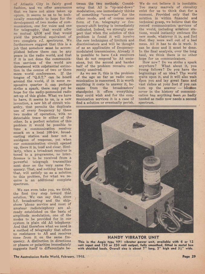
of Atlantic City in fairly good fashion, and we offer assurances that we have not since taken up opium. I t seems to us to be technically reasonable to hope for the development of two modes of communication, one for voice and one for telegraphy, that would offer no mutual QRM and that would yield the practical equivalent of two complete r.f. spectrums. We furthermore suggest that this is a job that somehow must be accomplished before there can be any peace in the radio world, and that i f it is not done the communication services of the world are threatened with substantial extinction in the course of two or three more world conferences. I f the tongue of “Q .S.T.” can be heard around the world, if in some responsive quarter it can perhaps strike a spark, there may yet be hope for the sadly-pommeled radio set-up of this globe. W hat we have to have, it seems to us, is a new invention, a new bit of circuit wizardry, that permits the duplicate use of every frequency by these two modes of operation, with no detectable trace in either of the other. In a perfect solution of this problem it would be possible to tune a communication receiver smack on a local 100-kw. broadcasting station and hear not a smidgeon of response, yet when our communication circuit opened up, there it is, loud and clear. Similarly, when a broadcast receiver is tuned to a programme, no interference is to. be received from a powerful telegraph transm itter next door on the very same fre quency. That, and nothing less than that, will satisfy us as a solution to this problem, for what we require is an additional complete spectrum.
We can even take you, we think, the first tiny step toward that solution. We can say that, since h.f. broadcasting and the ship- shore ’phone service and most of amateur radiotelephony are already established on the basis of amplitude modulation, one of the modes to be provided for in our system is plain old A3 telephony. And that therefore what we need is a method of telegraphy that offers no resistance to A3 and receives none from it on the same fre quency. A distinction in directions or phases or polarities immediately suggests itself to differentiate be
tween the two methods. Considering that A3 is “up-and-down” modulation, one immediately thinks of something “crosswise” for the other mode, and of course some form of f.m. telegraphy or fre- quency-shift keying is immediately indicated. Indeed, we strongly suspect that when the solution of this problem is found it will involve the new techniques of limiters and discriminators and will be thought of as an application of frequency- modulated transmission. Already it is possible to have f.s.k receivers that do not respond to A3 emissions, but the second and harder half of the problem remains currently unsolved.
As we see it, this is the problem of the age as fa r as radio communication is concerned. I t is worth anything it costs to answer it, because from the broadcasters’ standpoint it offers everything they could wish and fo r the communication services it is a case of find a solution or eventually perish.
We do not believe it is insoluble. Too many marvels of circuitry exist for us to think that for a moment. Provided only that the solution is within financial and technical grasp, we believe that the record communication services of the world, including amateur stations, would instantly embrace the new mode, whatever it is, and feel that they were well out of a bad mess. All it has to do is work. It can be done and it must be done. In the final analysis, over the long haul, we think there is no other hope for us communicators.
How now? Do we strike a spark anywhere ? W hat about it, you young fellows ? Do you have the beginnings of an idea? The world waits upon it, and it will also w ait upon you and lay great fam e and vast riches at your feet if you can turn up the answer — because never in the history of communication has anything been so badly needed as radio now needs a second spectrum.
HANDY VIBRATOR UNITThis is the Aegis type VP1 vibrator power unit, available with 6 or 12 volt input and 1 SO or 250 volt output, fu lly smoothed, fitted in metal box w ith shielded leads. Overall size is about 7 " long, 5 " high and 3 1 " wide.
The Australasian Radio World, February, 1948. Page 29
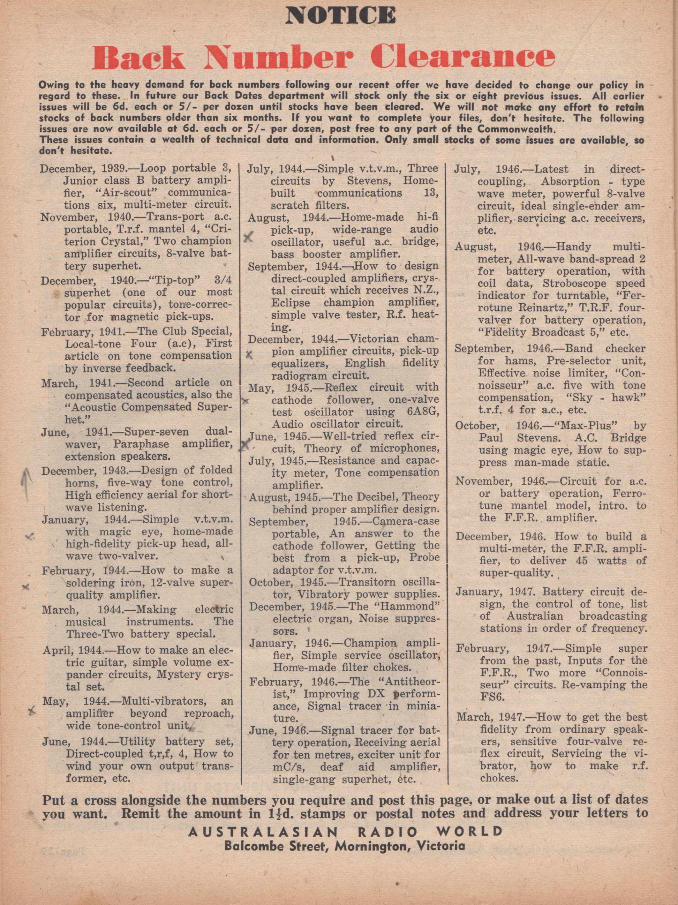
NOTICE
Back Number ClearanceOwing to the heavy demand for back numbers following our recent offer we have decided to change our policy in regard to these. In future our Back Dates department w ill stock only the six or eight previous issues. A ll earlier issues w ill be 6d. each or 5 / - per dozen until stocks have been cleared. We w ill not make any effort to retain stocks of back numbers older than six months. I f you want to complete your files, don't hesitate. The following issues are now available at 6d. each or 5 / - per dozen, post free to any part of the Commonwealth.These issues contain a wealth of technical data and information. Only small stocks o f some issues are available, so don't hesitate.
December, 1939.— Loop portable 3, Junior class B battery amplifier, “Air-scout” communications six, multi-meter circuit.
November, 1940.— Trans-port a.c. portable, T .r.f. mantel 4, “Criterion Crystal,” Two champion amplifier circuits, 8-valve battery superhet.
December, 1940.— “Tip-top” 3/4 superhet (one of our most popular circuits), tone-correc- tor for magnetic pick-ups.
February, 1941.— The Club Special, Local-tone Four (a .c), F irst article on tone compensation by inverse feedback.
March, 1941.— Second article on compensated acoustics, also the “Acoustic Compensated Supers e t .”
June, 1941.— Super-seven dual- waver, Paraphase amplifier, extension speakers.
December, 1943.— Design of folded horns, five-way tone control, High efficiency aerial fo r shortwave listening.
January, 1944.— Simple v.t.v.m. - with magic eye, home-made
high-fidelity pick-up head, allwave two-valver. v
February, 1944.— How to make a ^ soldering iron, 12-valve super
quality amplifier.March, 1944.— Making electric
musical instruments. The Three-Two battery special.
April, 1944.— How to make an electric guitar, simple volume expander circuits, Mystery crystal set.
May, 1944.— Multi-vibrators, an > amplifier beyond reproach,
wide tone-control unit,June, 1944.— U tility battery set,
Direct-coupled t,r ,f , 4, How to wind your own output transformer, etc.
Ju ly , 1944.— Simple v.t.v.m., Three circuits by Stevens, Home- built communications 13, scratch filters.
August, 1944.— Home-made hi-fi pick-up, wide-range audio oscillator, useful a.c. bridge, bass booster amplifier.
September, 1944.—How to design direct-coupled amplifiers, crystal circuit which receives N.Z., Eclipse champion amplifier, simple valve tester, R .f. heat- ing.
December, 1944.— Victorian cham-^ pion amplifier circuits, pick-up
equalizers, English fidelity radiogram circuit.
May, 1945.— Reflex circuit withX cathode follower, one-valve
test oscillator using 6A8G, Audio oscillator circuit,
une, 1945.— W ell-tried reflex circuit, Theory of microphones,
Ju ly , 1945.— Resistance and capacity meter, Tone compensation amplifier.
■ August, 1945.— The Decibel, Theory behind proper amplifier design.
September, 1945.— Camera-case portable, An answer to the cathode follower, Getting the best from a pick-up, Probe adaptor for v.t.v.m.
October, 1945.— Transitorn oscillator, Vibratory power supplies.
December, 1945.—The “Hammond” electric organ, Noise suppressors. '
January, 1946.— Champion amplifier, Simple service oscillator, Home-made filter chokes.
February, 1946.— The “Antitheorist,” Improving DX performance, Signal tracer in miniature.
June, 1946.— Signal tracer for battery operation, Receiving aerial fo r ten metres, exciter unit for mC/s, deaf aid amplifier, single-gang superhet, 6tc.
Ju ly , 1946.— Latest in direct- coupling, Absorption - type wave meter, powerful 8-valve circuit, ideal single-ender amplifier, servicing a.c. receivers, etc.
August, 1946..— Handy multimeter, All-wave band-spread 2 for battery operation, with coil data, Stroboscope speed indicator for turntable, “Fer- rotune Reinartz,” T .R .F. four- valver for battery operation, “Fidelity Broadcast 5,” etc.
September, 1946.— Band checker fo r hams, Pre-selector unit, Effective noise limiter, “Connoisseur” a.c. five with tone compensation, “Sky - hawk” t.r.f. 4 for a.c., etc.
October, 1946.— “M ax-Plus” by Paul Stevens. A.C. Bridge using magic eye, How to suppress man-made static.
November, 1946..— Circuit for a.c. or battery operation, Ferro- tune mantel model, intro, to the F .F .R . amplifier.
December, 1946. How to build a multi-meter, the F .F .R . amplifier, to deliver 45 w atts of super-quality. (
January, 1947. B attery circuit design, the control of tone, list of ■ Australian broadcasting stations in order of frequency.
February, 1947.— Simple super from the past, Inputs for the F .F .R ., Two more “Connoisseur” circuits. Re-vamping the FS6.
March, 1947.— How to get the best fidelity from ordinary speakers, sensitive four-valve reflex circuit, Servicing the vibrator, how to make r.f. chokes.
Put a cross alongside the numbers you require and post this page, or make out a list of dates you want. Remit the amount in lid . stamps or postal notes and address your letters to
A U S T R A L A S I A N R A D I O W O R L D Balcombe Street, Mornington, Victoria
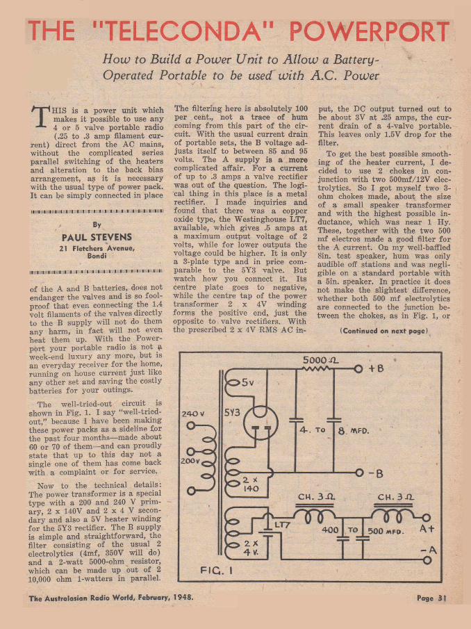
THE "TELECONDA" POWERPORTHow to Build a Power Unit to A llow a Battery- Operated Portable to be used with A .C . Power
TH IS is a power unit which makes it possible to use any
4 or 5 valve portable radio (.25 to .3 amp filament cur
rent) direct from the AC mains, without the complicated series parallel switching of th e heaters and alteration to the back bias arrangement, as it is necessary with the usual type of power pack. I t can be simply connected in place
iiin in iiiiiiiiiiiiiiiiiiiiiin iiiiiiiiiiiiiiiiiiiiiiiiim n iiiim iii
By
PAUL STEVENS21 Fletchers Avenue,
Bondi
| | | l | l l l l l l l l l l l l H l l l l l l l l l l l f l H I I H I I i l l l l l l |H I |l l l l l H , U , U ||l l |ll .
of the A and B batteries, does not endanger the valves and is so foolproof that even connecting the 1.4 volt filaments of the valves directly to the B supply will not do them any harm, in fa ct will not even heat them up. W ith the Power- port your portable radio is not £ week-end luxury any more, but is an everyday receiver for the home, running on house current ju st like any other set and saving the costly batteries fo r your outings.
The well-tried-out circuit is shown in F ig . 1. I say “well-tried- out,” because I have been making these power packs as a sideline for the past four months— made about 60 or 70 of them— and can proudly state that up to this day not a single one of them has come back with a complaint or for service.
Now to the technical details: The power transform er is a special type with a 200 and 240 V primary, 2 x 140V and 2 x 4 V secondary and also a 5V heater winding fo r the 5Y3 rectifier. The B supply is simple and straightforward, the filter consisting of the usual 2 electrolytics (4m f, 350V will do) and a 2-w att 5000-ohm resistor, which can be made up out of 210,000 ohm 1-watters in parallel.
The filtering here is absolutely 100 per cent., not a trace of hum coming from this part of the circuit. W ith the usual current drain of portable sets, the B voltage adju sts itself to between 85 and 95 volts. The A supply is a more complicated affair. F o r a current of up to .3 amps a valve rectifier was out of the question. The logical thing in this place is a metal rectifier. I made inquiries and found that there was a copper oxide type, the Westinghouse LT7, available, which gives .5 amps a t a maximum output voltage of 2 volts, while for lower outputs the voltage could be higher. I t is only a 3-plate type and in price comparable to the 5Y3 valve. But watch how you connect it. Its centre plate goes to negative, while the centre tap of the power transform er 2 x 4V winding forms the positive end, ju st the opposite to valve rectifiers. W ith the prescribed 2 x 4V RM S AC in
put, the DC output turned out to be about 3V a t .25 amps, the current drain of a 4-valve portable. This leaves only 1.5V drop fo r the filter.
To get the best possible smoothing of the heater current, I decided to use 2 chokes in conjunction with two 500mf/12V electrolytics. So I got myself two 3- ohm chokes made, about the size of a small speaker transform er and with the highest possible inductance, which was near 1 Hy. These, together with the two 500 m f electros made a good filter for the A current. On my well-baffled 8in. test speaker, hum was only audible off stations and was negligible on a standard portable with a 5in. speaker. In practice it does not make the slightest difference, whether both 500 mf electrolytics are connected to the junction between the chokes, as in Fig. 1, or
(Continued on next page)
The Australasian Radio World, February, 1948. Page 31
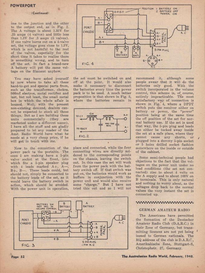
POWERPORT(Continued)
one to the junction and the other to the output end, as in Fig. 2. The A voltage is about 1.35V for .25 amps (4 valves) and little less than 1.3V for .3 amps (5 valves). I f one valve burns out on a 4-valve set, the voltage goes close to 1.5V, which is not harmful to the rest of the valves, especially fo r the short time it takes to realise there is something wrong, and to turn off the set. In fa ct a brand-new A battery will put the same voltage on the filament anyhow.
You may have asked yourself by now where to take all these hard-to-get and special parts from, such as the transform er, chokes, 500mf electros, metal rectifier and last, but not least, the small metal box in which the whole affair is housed. Well, with the present non-existing demand, dealers cannot be expected to stock all these things. But as I am building these units commercially (they are marketed under a different name),I have all the stuff and am gladly prepared to let any reader of the Aust. Radio World have what he needs at a very cheap price, if he will get in touch with me.
Now to the connection of the power pack t# the portable. The ones I am making have a 5-pin valve socket at the front, into which fits a 5-pin speaker plug with 4 leads marked A + , A— , B + , B— . These leads could, but should not, simply be connected to the battery leads of the set, as it would leave the battery switch in action, which should be avoided. W ith the power unit in operation,
the set must be switched on and off at the point. I t would also make it necessary to disconnect the batteries every time the power pack is to be used. A much better proposition is that shown in F ig. 3, where the batteries remain in
place and connected, while the four connecting wires are directly soldered to the corresponding points on the chassis, leaving the switch out. In this case the set will work from the power pack with the battery switch off. I f that switch was put on, the batteries would work as buffers in conjunction with the power unit and would also receive some “charge.” B ut I have not tried this out and so I will not
recommend it, although some people swear that it will do the batteries only good. W ith the switch incorporated in the volume control, this scheme is, ofs course, entirely impracticable. The most satisfactory way of connection is shown in F ig. 4, where a DPDT switch puts the receiver either on battery or power, the “power” position being at the same time the off position of the set fo r normal battery use. I f the set is used that way, the 5-pin plug and leads can either be tucked away inside the set at a safe place, where they cannot cause any shorts, or plugged into a dummy 5-pin socket or 5 holes drilled socket fashion somewhere on the inside or outside of the cabinet.
Some semi-technical people had objections to the fact th at the voltages on the power unit under no load conditions (the set not connected) rise to about 4 volts on the A supply and to about 160V on B terminals. This is only natural and nothing to worry about, as the voltages drop back to the normal values the very instant the set is connected up.
GERMAN AM ATEUR RADIO
The Americans have permitted the formation of the Deutscher Amateur Radio Club (D.A.R.C.) in their Zone of Germany, but transm itting licences are not yet being issued to German nationals. The HQ address of the club is D.A.R.C., Amerikanische Zone, S tu ttgart-S , Christophstr. 27, Germany.
Page 32 The Australasian Radio World, February, 1948.
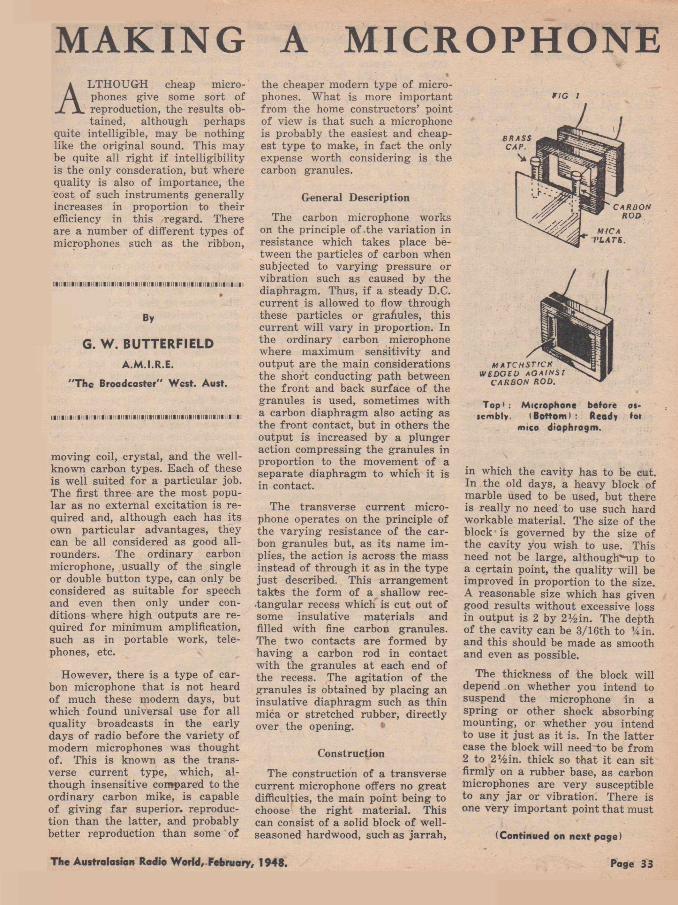
MAKING A MICROPHONEA LTHOUGH cheap micro
phones give some sort of reproduction, the results obtained, although perhaps
quite intelligible, may be nothing like the original sound. This may be quite all right if intelligibility is the only consderation, but where quality is also of importance, the cost of such instruments generally increases in proportion to their efficiency in this regard. There are a number of different types of microphones such as the ribbon,
I l l l l l l l i l l l l l l l l l l l l l l l l l U l l l l l l l l i l l l l l i l l l l l l l l l l l l l l l l l l l l l l l l l l l l l
By
G. W. BUTTERFIELDA.M.I.R.E.
"The Broadcaster" West. Aust.
moving coil, crystal, and the well- known carbon types. Each of these is well suited for a particular job. The first three are the most popular as no external excitation is required and, although each has its own particular advantages, they can be all considered as good all- rounders. The ordinary carbon microphone, usually of the single or double button type, can only be considered as suitable fo r speech and even then only under conditions where high outputs are required for minimum amplification, such as in portable work, telephones, etc.
However, there is a type of carbon microphone that is not heard of much these modern days, but which found universal use for all quality broadcasts in the early days of radio before the variety of modem microphones was thought of. This is known as the transverse current type, which, although insensitive compared to the ordinary carbon mike, is capable of giving fa r superior, reproduction than the latter, and probably better reproduction than some of
the cheaper modern type of microphones. W hat is more important from the home constructors’ point of view is that such a microphone is probably the easiest and cheapest type to make, in fa ct the only expense worth considering is the carbon granules.
General Description
The carbon microphone works on the principle of .the variation in resistance which takes place between the particles of carbon when subjected to varying pressure or vibration such as caused by the diaphragm. Thus, i f a steady D.C. current is allowed to flow through these particles or granules, this current will vary in proportion. In the ordinary carbon microphone where maximum sensitivity and output are the main considerations the short conducting path between the front and back surface of the granules is used, sometimes with a carbon diaphragm also acting as the front contact, but in others the output is increased by a plunger action compressing the granules in proportion to the movement of a separate diaphragm to which it is in contact.
The transverse current microphone operates on the principle of the varying resistance of the carbon granules but, as its name implies, the action is across the mass instead of through it as in the type ju st described. This arrangement takfes the form of a shallow rec- ■tangular recess which is cut out of some insulative m aterials and filled with fine carbon granules. The two contacts are formed by having a carbon rod in contact with the granules at each end of the recess. The agitation of the granules is obtained by placing an insulative diaphragm such as thin mica or stretched rubber, directly over the opening.
Construction
The construction of a transverse current microphone offers no great difficulties, the main point being to choose the right m aterial. This can consist of a solid block of well- seasoned hardwood, such as jarrah ,
r/c i
Top* : Microphone before at- •e m b ly . (Bottom !: Ready >ot
mica diaphragm.
in which the cavity has to be cut. In the old days, a heavy block of marble used to be used, but there is really no need to use such hard workable material. The size of the block is governed by the size of the cavity you wish to use. This need not be large, although'Mp to a certain point, the quality will be improved in proportion to the size. A reasonable size which has given good results without excessive loss in output is 2 by 2% in. The depth of the cavity can be 3/16th to %in. and this should be made as smooth and even as possible.
The thickness of the block will depend on whether you intend to suspend the microphone in a spring or other shock absorbing mounting, or whether you intend to use it ju st as it is. In the latter case the block will need to be from2 to 2% in. thick so that it can sit firmly on a rubber base, as carbon microphones are very susceptible to any ja r or vibration. There is one very important point that must
(Continued on next page)
The Australasian Radio W orld, February, 1948. Page 33
HAM NOTES
C A L L I N G CQ!By Don Knock, V K 2N O
L ONG before these lines reach print trans-Tasm an and interstate QSO’s in the 50- 54 mC/s band will be
commonplace . . . they are almost that as this is written. I t has long been expected that something of the kind would occur and to some of the old pre-war 5-metre addicts . . . the tie-up with N is the culmination of long weary periods of calling and waiting. I t is likely that by early 1948 there will have taken place a few overseas contacts even farth er afield. . . . KH6’s have already been heard a t various points in Eastern Australia . No better illustration of the doings in V K on “ Six” can be given than the contents of a letter from Eric Ferguson, VK3BD, who tells the story of the big breakthrough as seen from Victoria. He says: “Actually interest was whetted on Saturday evening when a number of weak unidentifiable
From M art Chaffer, VK3MH, Ballarat, V ic.: “I noticed an article in A.R.W. fo r November on the Windom aerial by VS1AA, and forwarded by VK2CM. Let me tell you I have used the Windom system (or SW F) since 1928, and swear by it. I actually put it up at the time the American Fleet visited Melbourne, around 1928, and have used it ever since. In fact, I am using the original piece of wire I put up a t that time! I would not use any other system as it is useful on 80, 40, 20 and 10 metres. W hat I like about this aerial is that one erects the 67% feet to best advantage in the location, irrespective o f where the shack is. Then all one does is to
signals appeared. These were heard by most active VK3 stations, and during a post-mortem late that evening VK3RR said that he was certain that he heard ZL prefixes. We decided to make an early start on Sunday (December 21) and the first station on the band was probably VK3HT who switched on his receiver at 8 a.m. During the first half-hour he heard two ZL’s and commenced calling them, but without success. I started listening about 9 a.m., and was ju st in time to hear Owen (V K 20C ) make what we take to be the first VK/ ZL 50 mC/s contact. A t this time ZL’s 1CD, 1HY and 1AO were R5 S5/7 here. Immediately following V K 20C ’s contact, VK7AB and ZL- 1HY made contact, followed by VK2HT. (In Sydney a t the same time VK2NP contacted ZL3LB.— D .B.K .) As time moved on, the ZL’s built up in strength until steady S9 was reached and, of
bring in the feeder to where the R ig is, whether in the lounge or— ! There is no worry about feeder length. The outfit here is 89 trite t from 3.5 mC/s crystal, 807 buffer- doubler or quadrupler, driving a Taylor T40. The receiver is 17 years old and is a 4-tube T R F type. The only difference between now and 17 years ago is a new dial, plus a 956 in place of the original 78 R F valve. The detector is still the same old 78 . . .”
These observations from OT M art (once 3X F of Moonee Ponds) prompt the question: How many active stations are today making use of early type equipment? If you are operating your station with TBO/46’s or D E T l’s, write and tell us about it.
course, the word went around that the D X was ‘on,’ and VK3’s began to hop in for their share. The condition lasted until approximately 10 a.m. Up to that time I had heard ZL’s 1CD, 1HY, 1AO, 1GG, V K 20C and V K 4ES. Now we come to the afternoon when things really happened. A little a fte r 3 p.m. the ZL’s again made their appearance, followed by VK7’s and VK2’s. A t one period between 1635 and 1700 hrs the band sounded like 20 metres . . . or, should I say, part of the band—■ more about th at anon— as ZL’s, VK7’s, VK2’s and VK4’s were all romping through with S9 peaks. The section of the band 50-50.3 mC/s sounded like the 20-metre Yank phone section. Th,e VK2’s and VK4’s appeared only fo r two brief periods during the afternoon and I could hear V K 7’s working V K2’s whenever the 7’s became audible here . . . about every 30 minutes. They would appear suddenly a t S9 and fade completely a fter 15 minutes.
“I t would appear th at VK7 had the best say so fa r as V K is concerned, as they worked all States excepting, of course, the elusive VK6. VK3 managed VK2, 4, 7 and ZL1, 2 and 3. I believe a ZL4 was heard here but have no information i f worked or not. Judging by the calls of the ZL stations I ’m doubtful if a ZL/VK4 contact eventuated, but this may have happened when the ZL’s were not audible here in VK3. The day was a real kick for the VK3 country enthusiasts as we could hear ZL’s working with such stations as 3AGB, 3UI, 3 F F and 3K X , who cannot do much good with metropolitan signals. In fact, I think that every active VK3 station excepting myself got its share of the ZL’s. The ZL stations were audible here from 1500 to 2130 hours. From 1500 until 1900 hours signals were very steady with the m ajor-
A WORD TO THE WINDOM
Th« Australasian Radio World, February. 1948. Page 35

MICROPHONE(Continued)
be observed in finishing off the block and that is to be sure that the face is perfectly true and flat. This is of vital importance as the mica diaphragm which covers the cavity will buckle if there is the slightest unevenness.
The diaphragm should be split off a sheet of mica until an even thickness of approximately 0.002in. is obtained. The size should be sufficient to overlap by a t least a quarter of an inch all round, and it can be then fixed into position. Thi’i shellac varnish is suitable for this as the mica can be gently smoothed into position as it forces any excess from beneath it. Quick setting glues should not be used as they may quickly form into lumps underneath the diaphragm before it can be pressed into position, thus causing the warping mentioned before.
A cover to protect the diaphragm can be made by sandwiching a square of gauze wire between a bakelite fram e and another fram e of exactly the same size made of thin cardboard. These can then be screwed down around the overlapping edges of the diaphragm ; the width of the fram e should be sufficient to allow the screws to clear the edge pf the mica, otherwise the la tter will tend to buckle as the screws are driven through it. Before going this far, however, it will be necessary to mount a carbon rod a t each end of the cavity. These can be obtained from an old dry-cell, but care should be taken to be sure that they are perfectly clean. Polishing with fine sandpaper will ensure this. The metal tops can be le ft in position, as they form a simple means of soldering a wire connection which can be brought out through a hole to the back of the block fo r terminals.
Alternative Method
Instead of using a block fo r the body of the microphone, anothef1 method is to use two sheets of bakelite or sim ilar material! The centre is cut out of one of these sheets to the size you wish to
make the cavity. I t is then laid flat on the other sheet and sealed or screwed down. Care should be taken to ensure that the jo in t is made air tight to exclude any moisture from reaching the carbon granules. This is shown, in the order of its assembly in F ig . 1. The carbons can also be seen in place. These should be a tight fit and can be held in position by cement such as “Tarzan Grip” applied a t the bottom and back; a matchstick cemented a t the side will also help. Brass or copper strips or rods can be used instead of carbon but it will be necessary
FIG 2.
to have them gold plated to avoid corrosion. I f these are used, a threaded brass rod can be tapped into the back of each one a t the centre; this rod can then be passed through holes to the back of the block, thus forming an excellent method of bolting the contact rods in position and at the same time acting as terminals.
Before final assembly, a small hole should be drilled in the top through which to pour the carbon granules. This can best be done by using a paper funnel fo r the purpose. The granules should only be allowed to trickle in to avoid jam ming in th§ hole; at the same time, the block should be tapped down on something solid to ensure that they completely fill all the space to within approximately l/16in. of the top. The hole should then be plugged and sealed off. On no account should the fine polished granules be handled, otherwise they will be inclined to stick together la ter on, thus m arring the microphone’s performance. Although carbon granules may be obtained from an old P.M.G. microphone or sim ilar type, it is fa r better to use a much finer grade, otherwise the quality may not come up to expectations.
Connecting to Amplifier
The method of connecting the microphone to the amplifier is shown in F ig . 2. A 4% -volt b attery should supply sufficient excitation, but up to nine volts can be used i f you are unable to get sufficient output. However, the lower voltage with extra amplification will give the best results. As with all carbon microphones a transform er with a low impedance primary will be required to provide the coupling to the high impedance grid circuit. This usually means a step-up ratio of from 30-1 to 75-1 dependent on the , actual impedance. However, if you ' are unable to procure one suitable, it is possible to make one by carefully removing the primary winding from an old L .F. transform er and replacing this winding by another consisting of 200 turns of wire with tappings brought out at each fiftieth turn. These tappings will enable you to obtain the best match possible. This is not a very difficult procedure as there is usually a fairly thick insulative layer between the primary and secondary windings, so you need have no fe a r of spoiling the latter provided you take reasonable care. The main thing to watch is that you do not break the input and output leads to this secondary winding, particularly the former, as it would be impossible to pick this up again.
v .v .v ,v ,v .v .v .v .v .v .w .,>
Harry C. Hickin, chemical engineer of Sydney, Australia, visited New York recently and learned to his surprise that there was a Keller Hickin in the same profession. Harry introduced himself to Keller, whereupon they found a commop English ancestry, P a rry ’s forbears moving to Australia in 1800, while Keller’s came to America in 1880. Thinking to be funny, Harry said, “I suppose you are also a ham.” In the dead silence that followed, W 20U T exchanged a card with Harry, second op a t VK2ACX. Taking note of this, a bystander exclaimed, “I ’ll bet your wives have the same names!” To this the two hams answered in chorus— “M arjorie.” Being in the RCA Building, there was only one thing to do: the boys adjourned to the Down-Under Bar, where skeds were arranged over a “Sydney Sling.”— “Q.S.T.”
Page 34 The Australasian Radio W orld, February, 1948.
HAM NOTES(Continued)
ity at S8. From 1900 until 2130 hours signals were affected- to a greater extent by fading and, excepting for ZL1HY, were peaking at S6. ZL1HY was the outstanding signal, a t times pegging theS meters. Here is a list of stations heard here during the day: ZL1AO, 1HY, ION, 1NL, 1CD, 1GG, 2RT, 2DS, 2PV and 3LB. VK7CW, 7XL, 7PW, 7NC and 7AB. YK2BZ, 20C and 2ADT. K V 4ES, 4AW and 4FB . I was not able to work any due to the fact that I am forced to use an indoor aerial at this location— people next door objected to a beam overlapping their property. About the activity a t the low frequency end of the band . . . it was particularly noticeable that almost all the ZL’s were crowded between 50 and 50.2 mC/s. The highest frequency I heard used was 50.6 mC/s. From observations here the ZL’s invari-
RADIOMAC NAME PLATES
Plote size 1 x Brass le tte rin g onblack. The fo llow ing title s are a va ila b le :—
A BATTERY LOW RECEIVEB BATTERY MICROPHONE RECTIFIERC BATTERY SPEAKER REGENER
ATIO NAERIAL M ILLIAM PS SHORT W AVEATTENUATOR MIXER SELECTIVITYBAND SET MONITOR SELECTORBAND SPREAD MODULATOR SWEEPB.F.O. NEUTRALISER SYNCBROADCAST OFF-ON TONECRYSTAL OHMS TUNERBUFFER OSCILLATOR TRANSM ITCURRENT OUTPUT VOLTSC.W. PRE AMP VERNIERDOUBLER PHONE VOLUMEEARTH PHONES WAVEFILAM ENT PICK-UP CHANGEFOCUS PLATE X SHIFTGAIN PLAY BACK X AM PGRID POWER Y AM PINPUT POWER-AMP Y SHIFTINTENSITY RECORD HIGHKEY R ADIATIO N
4d. eachSPEAKER
PRICES RADIO,5 & 6 Angel Place
Sydney
ably tune from the low frequency end of the band (we do also) and do not appear to tune above about50.5 mC/s. VK3 stations within the limits of 50 to 50.5 mC/s had by fa r the best spin. I heard some of the VK3’s who operate around 51-52 mC/s frantically calling, and invariably the station called either came back to someone a t the low frequency end or with a CQ. A few V K3’s could do no good until they moved, so adding to the QRM at the L F end. I had the same experience myself when the VK4’s were rolling in last Ju ly. My normal frequency a t that time was 51.88 mC/s and I called and called without result until I shifted to 50.3 mC/s, when I ju st couldn’t miss. The same applies to other bands, particularly 10 metres, where the L F end is bedlam at times, and the middle and H F ends are barren of signals. Methinks this is a poor show in view of the fact that our official amateur organisations are struggling to hold present assignments. I f we are going to utilise merely a narrow portion of the bands, and if the powers that be become fully aware of it, I can see a slice coming off both the 6 and 10 metre bands. On Sunday, December 21, fo r example, out of approximately 50 stations audible on the band here, only one was higher than 52 mC/s, three between 51 and 52 mC/s, and the remainder crammed in between 50 and 51 mC/s.”
The Sydney PictureI t was a t 6 p.m. on Saturday
evening, December 20 last, when an S9 phone signal from ZL3AR appeared on 50.1 mC/s calling “CQ Six Metres . . . ZL3AR of Ashburton, New Zealand.” The rush by Sydney VK2’s, also the northern men, was memorable . . . everybody called him and everybody was puzzled for thirty minutes or more when ZL3AR replied to nobody, but ju st went on calling CQ. Gradually it dawned on one or two that something was amiss with ZL3AR’s receiver, a fa ct that he admitted after a while , . . saying, “I ’m not sure i f I ’ve found the band on this converter.” No other ZL’s being in evidence on Six . . . V K 20C of Wyong and VK2NO of Sydney both thought of the same thing a t almost the same time and adopted the expedient of calling New Zealand on Six for
replies on Ten . . . a ruse that brought immediate results. ZL4BN in Dunedin came back to both stations and reported S9 reception; in fact it was possible to use duplex. Thus did the first Six metre/Ten metre cross-band QSO’s occur between Australia and New Zealand. Nothing further happened with ZL that night . . . but on the Sunday morning some VK2s were on the job bright and early. I t is a m atter fo r time checking as to who actually made the first two- way VK/ZL on Six metres, but it was thought to be a toss between V K20C of Wyong and VK2NP of Sydney. The latter worked ZL3LB oh CW at 0815 hrs, December 21, 1947. N ext station to tie up with a ZL appeared to be V K 2W J, around 0830 hours, followed by VK2ZH. By 0900 hours the band was in full swing with V K 2’s working ZL1, 2 and 3 districts and ZL’s could be heard working with country VK2’s. As the morning progressed, ZL’s could be heard in communication with V K 3’s, 5’s and 7’s, but not with V K4’s. Throughout the day and evening, up to 2100 hours Sydney time, the strongest ZL in the Sydney region appeared to be ZL3AR, who by this time had got over the receiving problem, but ZL3LB ran him very close. A most interesting station with a consistently strong phone signal on 51.6 mC/s was ZL2MF of Wanganui, who had only 6 watts in a folded dipole aerial, fed with Tru-Rip cable (sim ilar to Nylex). Moreover, Barry was modulating an 807 doubler as the output stage, yet his signal was quite equal to several of the ZL 100-watters. The idea that only the L F end of the band was workable certainly did not work out in his case, fo r ZL- 2M F lacked no VK callers and contacts.
As the day wore on, ZL signals appeared to follow an hourly pattern, reaching good strength and then fading to zero, repeating this effect continuously. To add to the excitement the interstate V K ’s put in an appearance and 5’s and 7’s in particular added to the general hubbub.
Consensus of opinion in the Sydney area is that stations on the coastline have much better conditions for ZL than those farther inland, even in the W estern Suburbs. There, such stations as VK-
Page 36 The Australasian Radio World, February, 1948.
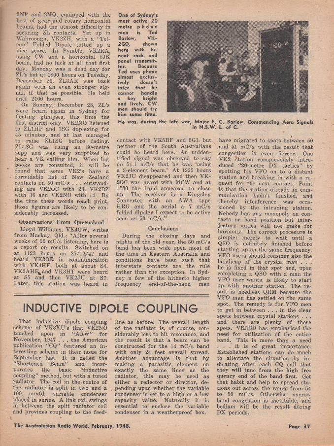
One of Sydney's most octive 20 metre p h o n e men is Ted Barlow, VK- 2GQ, shown here with his neat rack and panel transm itter. Because Ted uses phone almost exclusively doesn't infer tha t he cannot handle a key bright and lively. CW men should try him some time.He was, during the late war. Major E. C. Barlow, Commanding Aera Signals
in N.S.W. L. of C.
2NP and 2MQ, equipped with the best of gear and rotary horizontal beams, had the utmost difficulty in securing ZL contacts. Y et up in Wahroonga, VK2ZH, with a “Tel- con” Folded Dipole totted up a nice score. In Pymble, VK2RA, using CW and a horizontal 8 JK beam, had no luck at all that first day. Monday was a dead day for ZL’s but a t 1800 hours on Tuesday, December 23, ZL3AR was back again with an even stronger signal, i f that be possible. He held until 2100 hours.
On Sunday, December 28, ZL’s were heard again in Sydney for fleeting glimpses, this time the first district only. VK2NO listened to ZL1HP and 1SG duplexing for 45 minutes, and a t last managed to raise ZL1SG before fading. ZL1SG was using an 80-metre zepp and was very surprised to hear a VK calling him. When log books are consulted, it will be found that some VK2’s have a formidable list of New Zealand contacts on 50 mC/s . . . outstanding are V K 20C with 28, VK2BZ with 36 and VK2NO with 14. By the time these words reach print, those figures are likely to be considerably increased.
Observations" From QueenslandLloyd Williams, V K 40W , writes
from Mackay, Qld.: “A fter several weeks of 50 mC/s listening, here is a report on results. Switched on a t 1123 hours on 27/12/47 and heard VK3QR in communication with VK4HF, both a t about S4. VK2AHE^and VK3HT were heard at S5 and then V K 2JU at S7. Later, this station was heard in
That inductive dipole coupling scheme of V K3KU’s that VK2NO touched upon in “ARW ” for November, 1947 . . . the American publication “CQ” featured an interesting scheme in their issue for September last. I t is called the “Shortened Beam” and incorporates the basic “inductive coupling” method, but with a tuned radiator. The coil in the centre of the radiator is split in two and a 100 mmfd. variable condenser placed in series. A link coil swings in between the split radiator coil and provides coupling to the feed-
contact with V K 5BF and 5GL but neither of the South Australians could be heard here. An unidentified signal was observed to say on 51.1 mC/s that he was ‘using a 3-element beam.’ At 1225 hours V K 2JU disappeared and then VK- 20C was heard with MCW and at 1230 the band appeared to close up. The receiver is a Kingsley Converter with an AW A type HRO and the aerial a 7 mC/s folded dipole# I expect to be active soon on 50 mC/s.”
ConclusionsDuring the closing days and
nights of the old year, the 50 mC/s band has been wide open most of the time in Eastern Australia and conditions have been such that interstate contacts are the rule rather than the exception. In Sydney a few of the hitherto higher frequency end-of-the-band men
line as before. The overall length of the radiator is, of course, considerably less to hit resonance, and the result is that a beam can be constructed for the 14 mC/s band with only 24 feet overall spread. Another advantage is that by making a parasitic element on exactly the same lines as the radiator, this may be used as either a reflector or director, depending upon whether the variable condenser is set to a high or a low capacity value. Naturally it is essential to enclose the variable condenser in a weatherproof box.
»have migrated to spots between 50 and 51 mC/s with the result that congestion is even fiercer. One VK2 station conspicuously introduced “20-metre DX tactics” by spotting his VFO on to a distant station and breaking in with a request fo r the next contact. Point is that the station already in communication hadn’t finished, and thereby interference was occasioned by the intruding station. Nobody has any monopoly on contacts or band position but inter- jectory antics will not make for harmony. The correct procedure is simple: merely to wait until a Q S0 is definitely finished before starting up on the same frequency. VFO users should consider also the handicap of the crystal man . . . he is fixed in that spot and, upon completing a QSO with a man the VFO user wants, is likely to start up with another station. The result is needless QRM because the VFO man has settled on the same spot. The remedy is fo r VFO men to get in between . . . in the clear spots between crystal stations . . . and there are plenty of those spots. VK3BD has emphasised the need for utilisation of the entire band. This is more than a need . . . it is of great importance. Established stations can do much to alleviate the situation by indicating after each CQ call that they will tune from the high fre quency end of the band first. Get that habit and help to spread stations out across the range from 54 to 50 mC/s. Otherwise narrow band congestion is inevitable, and bedlam will be the result during DX periods.
INDUCTIVE DIPOLE COUPLING
The Australasian Radio World, February, 1948. Page 37
(l Jt M - M M r J f • C O N D U C T E D B\
2 > n o t t w a v e r ^ e v ie w L , . wNO TES FROM M Y D IA R Y
L o n d o n C a l l i n g
My copy of this overseas journal of the British Broadcasting Corporation, No. 426, and dated London, November 20, 1947, reached me on January 28. But whilst it was long delayed in reaching Erm- ington, it nevertheless did not seem backdated. I was particularly interested in "A Good Moment to Take Stock,” which was the text of Sir William Haley’s speech on the occasion of the BBC’s Silver Jubilee Year. It was on November 14, 1922— twenty-five years ago— that 2LO, London, sent out the first BBC programme. And from then till now the BBC has really set the standard for broadcasting, particularly that which we are interested in— short-wave transmissions and even at the risk of it being tiring to the old and regular readers of these pages I say again that the BBC is in my opinion the yardstick by which all S /W transmissions are measured.
I find on talking to many listeners, they, like myself, when they happen on a BBC programme, invariably listen and, whilst they may have been scanning the dial, they stop on the BBC programme, whereas, apart from satisfying themselves as to whom they are listening when they tune in a foreign station, they move on. And that reminds me when plenty of space was available and I printed long lists of stations in alphabetical order as regards countries, I was taken to task by the more venturesome listeners for giving so much space to the BBC frequencies. They said, "Anyone can tune the BBC .” And is that not a great compliment to the BBC? The fact that they have perservered and found frequencies that will reach almost all parts of the world more or less all day and night must be
very gratifying to their engineers.And what about during the re
cent war? W e listened to the news from the BBC and knew it was right— perfectly true; whereas we tuned to several countries and got a laugh out of their "news.” No, don’t pass the BBC by because they are easily tuned, but rather consider it a duty to tune to them regularly as a silent token for what they have done for shortwave broadcasting.
E x c l u s i v e V e r ie
The well-known South Australian Dx-er, Rex Gillett, has added another to this staff at Prospect. This time it is a fine bouncing baby boy. Rex already has a little girl, so, as he says, "with one of each, both he and his wife are quite satisfied.” He has verified 94 countries, so let’s hope the local listening-in will not prevent him from making his century soon. Congratulations, Rex.
W e d d in g B e l l s
D x listeners, particularly those who tuned to the overseas broadcast band, will remember Roy Hal- lett who conducted the pages devoted to that type of listening for one of our contemporaries. W ell, Roy has been and got married. I wondered why he had been so quiet and it was only through a letter from him that I learnt recently about the event. Congrats, Roy.
G r e e t i n g s F r o m N .Z .
And just to make this a really chummy page this issue, I quote a portion of a letter received from Rom R. Akersten, shortwave editor, Auckland Branch, New Zealand D X Radio Association Inc: "Greetings to you across the Tasman. At long last I have had a break in my correspondence, to be able to say 'Hullo’ and compliment you on your good work in 'Short- v/ave Review.’ I have read your S /W notes for some time now,
New StationsKZBU, Cebu City, 6.10mc,
49.15m : This new Philippine station operated by Philippine Broadcasting Corp. on both 1250kc and 6.10m c is on the air from 7 p.m. till 2.05 a.m. Signals are only fair to good, particularly late at night. This report comes from Rex Gillett.
JK A O , Korea, 9.43m c, 31.81m : Radio Australia reports this station as being logged from 8 .30 p.m. till11.30 p.m. From 9.45 till 10 o’clock the 'Voice of America’ is relayed. No programme in English has been heard but they announce, "This is the Korean Broadcasting Service.”
and have found them informative and stimulating for this grand hobby of Dx-ing.
"W ell, L .J.K ., a word or two about my rig here. I am using two receivers, a commercial 7-tube superhet and a super-regene comm, receiver, range 9 .4 to 100 metres, both fed from a rotary beam antenna and a V doublet inverted. Both have performed 100 per cent, in as much that I won the S /W Trophy for 1947 here in our Auckland Branch of the N .Z. D X Radio Association. About 250 loggings were made in the 1947 D X season, some eighty-odd verifying to date of writing.”
Page 38 The Australasian Radio World, February, 1948.
SAYS WHO?W G E X , New York, 9.67mc,
51.02m , gives news and sports news at 6.45 a.m. Times and frequency details given and address for reports— 641 Washington St., N'ew York 14 N .Y .— Miss Sanderson. (Latest sked to hand is: 6.30-S a.m.— L .J.K .)
Conditions have only been fair lately, the best listening times being between 5 a.m. and 8 .30 a.m., when there is quite a lot to be heard with fair ease. But after that the noise level is very high and it is quite impossible to hear anything with any degree of comfort.— Miss Sanderson.
Schedules for Tabriz are given as 7 p.m.-9.30 p.m. on 11.96mc and 12.30 a.m.-4.30 a.m. on 6.09 me on week days. On Fridays the schedule is 4 .30 p.m.-9 p.m. and12.30 a.m.-4.30 a.m. News in English is scheduled for 4 a.m.— L.J.K.
Polskie Radio, Warsaw, has been heard for past few weeks on 6.215 me. This is apparently to dodge interference from the Voice of U.S.A. on 6.10m c. English is broadcast as usual from 6 .50 a.m.- 7.10 a.m.— Rex Gillett.
X G O Y is now using 6.142m c in the service to North America. A two-hour broadcast in English is commenced at 12.30 a.m. Very fine signals.— Gillett.
Singapore heard at 8 p.m. on 21.720m c and at 8.15 VUD-8 21.510m c; EPB, 15.10mc, at 9 o’clock. A t 10 p.m. I heard Luxembourg on 15.35mc.— Akersten.
BBC General Overseas Service is on wavelengths considered suitable to Australia from 4 till 10 p.m., whilst of course a special regional programme is provided from 4- 5.45 p.m. During February they will be found in 19, 25 and 31 metre bands during the afternoon, whilst in the evening the 13 and 16 metre bands are added. It is considered these bands will hold out until end of April.— L.J.K .
And here are some of the loggings made by Miss Dorothy Sanderson :
CanadaCHOL, 25.60, 11.72, 6 .30 a.m.:
Service to Europe in French.
CKCS, 19.58, 15.32, 7 a.m.: News to Europe.
CHIS, 31.22, 9 .61 , 7 p.m.: Canadian Chronicle.
CKLO, 31.15, 9 .63, 7 a.m.: Christmas service in song and story.
C BLX, 19.88, 15.09, 10 p.m.: News in English and music.
C K C X, 19.75, 15.19, 9 .30 a.m.: News in English; music and sports news.
PhilippinesKZRC, 48.94, 6 .13, 9 p.m.;
News in English; QRM from VIR2.
KZPI, 31.58, 9 .50 , 9 .15 p.m.: Good musical programme.
K ZFM , 25.21, 11.90, 8.15 p.m.: People’s Station, news and music.
KZRH, 31.12, 9 .64, 8.45 p.m.: Music and news.
KZOK, 30.95, 9 .692 , 10 p.m.: Announced in English, but news in Philippino, and music.
India, Malaya, Ceylon, French Indo-China, Batavia, Java
V U D 8, 13.98, 21.51, 9 .30 p.m.: News in English for Africa and East Asia.
V U D 9, 25.27, 11.87, 9 .45 p.m.: News and music.
V U D ll , 31.06, 9 .66 , 10.15 p.m .: News and music.
Singapore, 19.61, 15.30, 8 .30 p.m .: News in French and music.
Singapore, 25.56, 11.73, 8.45 p.m .: News in Dutch and music.
Ceylon, 19.83, 15.12, 8 p.m.: News and music; Forces service.
Saigon, 25.47, 11.78, 8.15 p.m.: News in English and music.
Hanoi, 25.19, 11.91, 9.45 p.m.: News in French and Chinese; music.
Radio Francois, 49 .75 , 6 .03, 9 .30 p.m .: News in French.
Y D D 3, 31.41, 9 .55 , 7.45 p.m.: News in Dutch and English; music.
Y D C , 19.81, 15.14, 7 .30 p.m.: News in Dutch and English; music.
Y C N 3, 37.45, 8 .09, 10.15 p.m.: Western music and news in Dutch and dialect.
Y D B 4, 30.99, 9 .68, 10 p.m.: News in Dutch and English; Radio Batavia.
Y F A 4, 32.24, 9 .25, 9 .30 p.m.: Musical programme and news.
Ceylon, 16.84, 17.81, 10.45а.m.: BBC relay and music.
SHORTS
Vatican Radio was heard the other Thursday at 1 a.m. with news in English on 3 1.06m . . . think they were also on 19 metre band; possibly a daily service. Also on, I understand, at 4 .15 a.m. on 31 and 50 met. bands.— Hallett.
Radio Luxembourg gives its schedules as: 9-11 p.m. on 15.35 me, and 2.30-9 a.m. on 6.09m c— Gillett.
The "Voice of America” signs off on 6.17m c at 5 a.m. with "Star- Spangled Banner.” It opens onб.10mc a little later.— Gillett.
Paris can be heard at 3 .30 p.m. with news in French and musical programme on 11.845m c, 25.33m , and at 3.45 with news in French on 9.56m c, 31.37m , whilst at 6.30 a.m. on 7.28mc, 4 1 .21m.— Miss Sanderson.
Luxembourg is being heard as late as 10.45 p.m. on 15.35 m.c.— Akersten.
HCJB heard closing at 4 p.m. on Thursday, January 15, in English on 24 metre band. They announced they were also on 19 and 30 metre bands.— Hallett.
The Australasian Radio W orld, February, 1948. Paso 39
SU X on 7.865m c, 38.15m , is giving usual Arabic programme at6 a.m.— Miss Sanderson. '
EPB, "Radio Teheran,” amended schedule is from 8.30-10 .30 p.m. with English from 10.15-10.30.— L .J.K .
C B R X is a station I have not heard for a year or two on 6.15mc. I have logged them again at 2.15a.m. announcing as CBR, V ancouver.-—Gillett.
X G O Y v is now' using 6 .l42m c in the service to North America. A two-hour broadcast in English is commenced at 12.30 a.m. Very fine signals.-^Gillett.
W L K S, Kure, is back on 6.105 me from 7.30-11 .30 a.m., apparently having dropped the 2.46 channel.
Radio W E IN , Vienna, has moved from 7.17m c to 7.24m c.— D X N Z .
Damascus, Syria, is reported as on 7 .5 5mc as well as 6 .00 and11.985m c. Schedule is 3-4 p.m.; 9-10 p.m. and 2-7 a.m.— U R D X . ( I believe Damascus is also on 12.00m c in early mornings in Arabic but morse is prevalent.— L .J .K .)
Radio France, Hanoi, French Indo-China, 9.485m c. Address is 56 Rue Richaud.
Radio Tananarive, Madagascar, broadcasts regularly on shortwave
over three transmitters, in parallel on 6,063, 9 .669 and 10 .615mc. The broadcast hours are: 1.45-3.30 p.m.; 6 .20-8 .45 p.m. and 12.20а.m.-3.40 a.m. All reports should be sent to: Radio Tananarive, Office o f the French High Commissioner, Tananarivo, Madagascar. — "Shortwave Listener.”
O LR2A , Prague, is putting in a good signal at 4.45 a.m., when news in English is broadcast.— The N .Z. D X -T R A .
Latest QRA for reports to Radio Italiana is: Presidenza del Consig- lio dei Ministri, Servizio Radio- diffusioni per L ’Estero, V ia Vento 56, Rome, Italy.— "Radio News.”
H H Y M , Haiti, 6.00m c, 50m. Port-au-Prince is relatively ’ new station signing off at noon.— "Radio News.”
Syria. Damascus verifies from Republique Syrienne, Direction Generale des Postes, Telegraphes et Telephones, Damas (D am ascus), Syria.— Ken Boord.
C a p e V e r d e I s l a n d s
Here is one for those fortunate Dx-ers in a quiet district. I here; with quote "Shortwave Listener” : "W . J. Pye mentions a new one, but offers no times; he says, 'Once or twice recently Praia, Cape Verde Isles, has been putting in a good signal for its microscopic power onб.405m c.’ Our information is that CR5AA, Praia, Cape Verde Islands,
operates on 6400kc. 46.88m exactly, with a power o f 30 watts, on the following brief daily schedule: 6.30-8 a.m.”
N e w Z e a l a n d S.W .T r a n s m i t t e r s
The following are the frequencies allotted to the N .Z .B .S . shortwave transmitters: Z L1, 6 .08 me; ZL2, 9.54m c; Z L3, 11.78m c; ZL4, 15.28m c; ZL5, 17.77m c; ZL6, 25.80mc.
The above have a power of 7.5 kilowatts. Tests are apparently concluded but no advice has been received as to when they will take the air on full time.
D a t a o n G r e e n l a n d
The following comes by airmail from "Radio News,” Chicago:
"Greenland. 'W orld Handbook for Listeners,’ published by O. Lund-Johansen, 1 Lindorffsalle, Copenhagen Hellerup, Denmark, lists this data re radio in Greenland: Normal clock time is G M T m inus 3 hours; Q RA, Radiostation Godthaab, Greenland. Frequency 5.942m c (5 0 .4 9 m ). Power 1 kW . Daily programme at 7.45-8.45a.m. weather report 7 .45 ; news in Danish 8 o’clock; ships’ positions 8 .15 : news in Eskimo 8.30. Announcement in Danish is. 'God Aften; her Gronlands Radio.” Interval signal is chimes and first movement of six bars— played
GEORGE BROWN & C O . PTY. LTD.267 CLARENCE STREET, SYDNEY. Phone: M 2544
DISTRIBU TO RS TO TH E TRADE FOR
ROLA SPEAKERS • EVEREADY BATTERIES • AEGIS RADIO COMPONENTS • ULTIMATE RADIOS • MULLARD
VALVES • I.R.C. RESISTORSA nd A ll Brand L ine Radio Com ponents
★ AEGIS 4 V A LV E A N D 5 V A LV E K IT SETS COMPLETE N O W A V A IL A B L E
Page 40 The Australasian Radio World, February, 1948.
twice— of the Funeral March by Norman Andersen which was composed for Kjell Abel’s play, 'Silke- bourg’.”
T h e C r o s l e y C o r p o r a t i o n , C i n c i n a t t i
Shortwave frequency schedule, Eastern Standard Time, January, 1947:
W L W K : 3 a.m.-8 a.m., 15250 kc, 19.7m, Europe; 11 a.m .-l p.m., 17800kc, 16.8m, W . South America.
W L W O : 3 a.m.-6.15 a.m., 17800kc, 16.8m, Europe; 6.30a.m.-8 a.m., 9590kc, 31.3m, Europe; 11 a.m .-l p.m., 11790kc, 25.4m, E. South America.
W L W L : 2 a.m.-8 a.m., 2l690kc, 13.8m, Europe.
W L W R : 4 a.m.-8 a.m., 15350 kc, 19.5m, Europe; 15350kc, 19.5 m, North Africa; 9 a.m.-3 p .m .*, 11710kc, 25.6m : W . South America; 15250kc, 19.7m, W . South America.
W L W S: 3 a.m.-6 a.m., 2l650kc, 13.2m, Europe; 2l650k c, 13.2m, North Africa; 6.15 a.m.-8 a.m., 11705kc, 25.6m, Europe; 11705kc, 25.6m, North Africa; 10 a.m.-3 p.m., 6080kc, 49.3m , W . South America; 9700kc, 30.9m, W . South America.
* 10 a.m.-3 p.m. Monday only.
Here is an interesting item from Rex Gillett: "The following is from VU 7M C: Transmissions are three in number from 11.30 a.m.-1.40 p.m.; 6 .30 p.m.-7.40 p.m.; and 10 p.m.-2.40 a.m. Frequencies in use are 968kc and 6.065m c during each transmission. Power employed is 300 watts on 6.065mc, whilst 30 watts is used on 968kc. Plans are under way for increased power to 10 k.w. on the B /C band, and 5 k.w. on S /W . It is hoped the transmitter will be installed this year. News in English is scheduled for 12.30 p.m. and 10.30
p.m. VU7M C belongs to the Government of Mysore. Address is Akash-Vani Broadcasting Station, Mysore, India.”
V e r if ic a t i o n s
Miss Sanderson of Malvern, Victoria, writes: "Verifications have been coming along very well, and I have now some more cards to add to my collection. A card and letter from Radio National Espana for 9.38m c, two cards from Singapore for 6.77 and 11.73m c; a card and letter from the Forces Broadcasting Service in Benghazi, North Africa, which attest transmission on November 8. The frequency on which they did their test was11.850m c, and as they had to suspend the tests for the present they hope to resume shortly, according to their letter. Cards from Capetown, Johannesburg and Siam and a letter from EPB, Teheran, for a report sent in September last.”
Rex Gillett of Adelaide reports: "A few very decent veries have been finding their way.to my location, some of the best being: LK J, LK V (first report from Australia) : LLG (first report from Australia; C X A -19, Radio Luxembourg, 9.5275m c (first from Australia;; H I2T, 11.90; LRM ; Omdurman, 9 .70 ; VUTM C; ZPA -5; EQB; Radio Tabriz, 11.96 and 12.18; H JD E; C E1190; ZO Y, 4 .915 ; and X G O Y on 11.913, 15.17 and 7.153 ; J ’burg 4 .373 and 6.095.
"Others of lesser merit are ZL2, ZL3, Z L4; COBL; Singapore on11.74, 15.30, 9 .68 and 6.77; VUD- 7, 15 .16; V U D -11, 15 .29; VUD-8, 21 .51 ; VU D -9, 9 .67; C FRX, 6 .07; PCJ on 17.77, 11.735 and 9 .59 ; Radio Dakar, 11 .715 ; CHOL,11.715 ; and SEAC, 17.83 (but station quoted old frequency of 17 .77m c).
"Countries verified total 94, latest additions being Dominican Republic, Iran and Colombia.”
Rom R. Akersten, Auckland, N .Z., advises: "Among some of
my 'firsts’ reports I can count on are LRM, 'V. of A ,’ Manila, SBT and one or two N .A . low-powered M /W stations. Some of my recent veries came from: Singapore, 9 .69 me (second report from N .Z .), KZPI, 9.50m c; KZOK, 9.69m c; O A X 4J (2 0 0 w atts), 9.33m c; W X F G , Alaska, 12.25m c; X G O Y ,11.913m c; Y FA 4, 9.265m c; CSX2,ll.Om c; C X A 19, 11.835m c; HEU-6, 15.315m c; X E W W , 9.50m c; XEQ Q , 9.68m c; Luxembourg, 6.09 me; Z B W 3, 9.515m c; CE615,6.152m c; "F .B .S .,” Jerusalem, and SDB2, 10.78m c.”
DISPOSALS BARGAINS
Things must be much the same in England, according to the following paragraph by “D iallist” in the English Wireless World.
“I t ’s very interesting to spend an hour or two in exploring the contents of the shops which make a feature of war surplus radio gear. There’s a good deal of useful stuff to be picked up if you buy carefully; but there is also no small amount of elaborate apparatus, which, though it may be beautifully made and must originally have cost a tidy packet, is now of little practical use to the wireless man. There is always the temptation to buy this or that ju st because its present price is a mere fraction of what it cost to make. By spending a few pounds without much thought one might easily acquire a barrow load of gear of attractive appearance, fo r which it would eventually prove difficult to discover practical uses. Too often conversion which a t first sight appears so simple turns out, when you come to tackle the job, to be an involved and expensive business. From our point of view the trouble with a great part o f the war surplus radio material is that it was made fo r highly specialised purposes which don’t fit in with our normal requirements. There are naturally lots of " things— meters, fo r example, of various kinds— which are exactly what we long to possess, but as many others are filled with similar yearnings you don’t often find the good ones offered a t give-away prices.”
The Australasian Radio World, February, 1948. Page 41
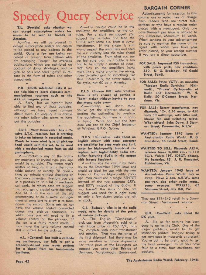
Speedy Query ServiceT.L. (Pymble) asks whether we
can accept subscription orders for issues to be sent to friends in America.
A.— Yes, we w ill be pleased to accept subscription orders for copies to be posted to any address in the world. Quite a few are being received at present from fellows who are arranging “ swaps" for overseas publications which are restricted on account of dollar shortages, and as g ifts to pals who send "g if ts " in return in the form o f tubes and other components.
• * •P.D. (North Adelaide) asks if we
can help him to locate disposals communications receivers such as the AR7 a t bargain prices.
A.— Sorry, but we haven't been able to find any of these bargains, although we have heard rumours about them. On enquiry it is always the other fellow who seems to have got the bargains.
* * *
S.D.S. (West Brunswick) has a 7 - valve S.T.C. receiver, but is starting to take an interest in recorded music. Wants to know what type of pick-up head would suit this set, to be used with a mechanical motor from an old gramophone.
A.— Practically any o f the ordinary magnetic or crystal type pick-ups would be suitable. The motor won't matter so long as it pulls the tu rn table around at exactly 78 revolutions per minute w ithout dragging on the heavy passages. Possibly you are in a position to do a b it of mechanical work, in which case we suggest that you get a crystal cartridge only, and f i t it to the arm o f the old gramophone or on a swivel arrangement of some sort to allow it to track across the record. Some sets do not have the volume control connected across the pick-up terminals, in which case you w ill need to f i t a volume control on the pick-up. If the set is a fa irly recent model it may have the set's volume control still in circuit for the pick-up.
* * *
A.L. (Concord) has bu ilt a cathode ray oscilloscope, but fails to get a properly-shaped sine w cr re pattern for a signal from his home-made oscillator.
A.— The troupe could be in the oscillator, the amplifiers, or the c.r. tube. For a start we suggest you suspect the oscillator and feed the C.R.O. w ith some a.c. from a power transformer. I f the shape is still wrong suspect the amplifiers and feed the a.c. directly into the tube ahead of the amplifier. From what you say we feel sure tha t the trouble is too bad to be simply a matter o f incorrect bias on the am plifier; looks more like a major error in the wiring, open circuited grid or something like that. Incidentally, the power supply is 50 cycle, not 60 as in America.
* * *R.L.S. (Broken H ill) asks whether
there is any chance of getting a "h a m " ticket w ithout having to pass the morse code exam.
A .— Frankly, we don't th ink you've got the slightest chance of getting the authorities to overlook the regulations, but there is no harm in trying. W rite and put the best case you can to the Chjef Inspector of Wireless, G.P.O., Sydney.
* * *
N.B.S. (Bairnsdale) asks about an English circu it with tone corrector pre-am plifier for grao work and t.r.f. tuner for high-quality broadcast reception, with h igh-fide lity audio amp lifie r featuring 6L6's in the output w ith inverse feedback.
A.-—This was the circu it by Hartley in the December 1944 issue and would be ideal for use w ith the new types of English h igh-fide lity pickups. You could use a single 6SN7GT instead of the two separate 6J5's, and 807's instead of the 6L6's. If you haven't this issue on file, we suggest you send for it right away as only a few dozen copies are left in stock.
* * *
C.S. (Sydney), who is in the radio trade, asks for details of the prices o f certain pick-ups.
A.— The English "Connoisseur" pick-ups from Magrath's sold at a nett trade price of £ 5 /1 2 /6 , plus tax, complete with input transformer and needles. That was the price of the firs t shipment, but there may be some variation in future shipments. For trade price of the Lexington we suggest you write John Bristoe of Denhams, Maryborough, Queensland.
BARGAIN CORN ERAdvertisements for insertion in this
column are accepted free o f charge from readers who are direct subscribers or who have a regular order placed w ith a newsagent. Only one advertisement per issue is allowed to any subscriber. Maximum 16 words. When sending in your advertisement be sure to mention the name of the agent w ith whom you have your order placed, or your receipt number if you are a direct subscriber.
FOR SALE: Improved FS6 transceiver, w ith power pack, new condition, £10. D. G. Bradshaw, 46 Gould Street, Bondi.
FOR SALE: Palec VCTV, as new,also "Modern Radio Servicing" (Ghi- ra rd i), "Drakes' Cyclopaedia of Radio and Electronics." W . H. Kelly, 30 O'Connor Street, Horsham, Vic.
FOR SALE: Rotary transformer, new disposals, 12v. 6.26 amps, to 450 volts 50 milliamps, with filte r unit, blower fan and switching relays. W hat offers? John Down, 3 Stewa rt Street, Parramatta, N.S.W.
W ANTED: January 1945 issue of Australasian Radio W orld. D. G. Bradshaw, 46 Gould Street, Bondi.
WANTED TO SELL: Disposals AR14, receiver tunes 16,000 kC /s to 11 0 kC/s. Valves 1 P5, 1 D8GT, phones. No batteries. £5. J. R. Dempster, Elphinstone, Vic.
W ANTED: January 1945 issue of Australasian Radio W orld, buy or swap. Have 2 doz. A.R.W., some pre-war, also other radio mags., some overseas. W X2213, 62 Shannon Street, Box H ill, Vic.
They are £ 1 9 /2 /6 retail in a Swan- ston Street (Melbourne) window.
* * *
G.H. (Caulfield) asks about the DX club.
A.— No, so fa r nothing has been done to revive the Club. One of the major problems would be to get stationery printed. Imagine trying to get envelopes in thousands at present! You've got to be pretty good to get the local newsagent to let you have four at a time, four envelopes, not packets.
Page 42 The Australasian Radio World, February, 1948.
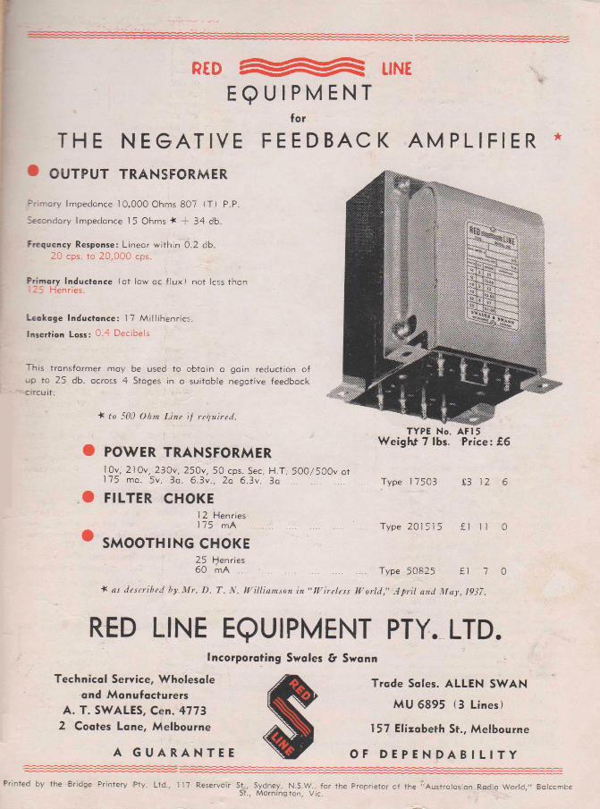
E Q U I P M E N Tfor
T HE N E G A T I V E F E E D B A C K A M P L I F I E R *• OUTPUT TRANSFORM ER
Primary Impedance 1 0,000 Ohms 807 (T) P.P.
Secondary Impedance 15 Ohms "K + 34 db.
F re q u e n c y R esponse : Linear within 0.2 db.20 cps. to 20,000 cps.
P r im a ry In d u c ta n c e (at low ac flux) not less then125 Henries.
L e a k a g e In d u c ta n c e : 17 Millihenries.
In s e r t io n L o s s : 0.4 Decibels
This transformer may be used to obtain a gain reduction of up to 25 db. across 4 Stages in a suitable negative feedback crrcuit.
to 500 Ohm Line if required.
Weighf 7 lbs. Price: £6• POWER TRANSFORM ER
1 0v, 210v, 230v, 250v, 50 cps. Sec. H.T. 500 /500v at175 ma. 5v. 3a. 6 .3v„ 2a 6.3v. 3a ................................. Type 17503 £3 12 6
• F ILTER CHOKE1 2 Henries175 m.A ..................................... Type 201515 £ 1 1 1 0
SM OOTHING CH OKE25 Henries60 rr.A .... .......................................... Type 50825 £ 1 7 0
* as described by Mr. D. T. N. Williamson in “Wireless World,” April and May, 1937.
RED LINE EQUIPMENT PTY. LTD.Incorporating Swales & Swann
Technical Service, Wholesale j f X Trade Sales. ALLEN SWANand Manufacturers f lV S A )
A. T. SWALES, Cen. 4773 MU 6895 (3 Lines)2 Coates Lane, Melbourne 157 Elizabeth St., Melbourne
A G U A R A N T E E OF D E P E N D A B I L I T Y
Printed by the Bridge P rintery P ty. Ltd., 117 Reservoir S t, Sydney, N.S.W. fo r the P roprietor o f the "A ustra las ian Radio W o rld ," BalcombeSt., M o rn ing ton , Vic.
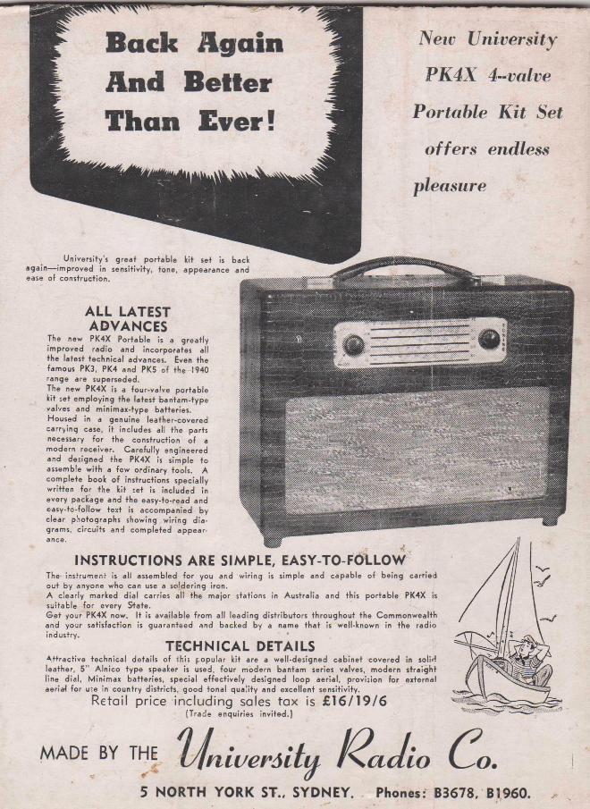
New University
PK4X 4-valve
Portable Kit Set
offers endless
pleasure
U n iv e rs ity 's g re a t p o r ta b le k it se t is b a ck a g a in — im p ro v e d in s e n s it iv ity , to n e , a p p e a ra n c e and ease o f c o n s tru c tio n .
A LL LATEST ADVANCES
The new PK 4X P o rta b le is a g re a t ly im p ro v e d ra d io a n d in c o rp o ra te s a ll th e la te s t te c h n ic a l a d va n ce s . Even th e fa m o u s PK3, PK 4 a n d PK5 o f th e 1940 ra n g e a re su p e rse d e d .The new P K 4X is a fo u r -v a lv e p o r ta b le k it se t e m p lo y in g th e la te s t b a n ta m - ty p e va lves and m in im a x - ty p e b a t te r ie s . H o u s e d in a g e n u in e le a th e r-c o v e re d c a r ry in g case, i t in c lu d e s a ll th e p a rts necessary fo r th e c o n s tru c tio n o f a m o d e rn re c e iv e r . C a re fu l ly e n g in e e re d an d d e s ig n e d th e PK 4X is s im p le to a ssem b le w ith a fe w o rd in a ry to o ls . A c o m p le te b o o k o f in s tru c t io n s s p e c ia lly w r it te n fo r th e k it se t is in c lu d e d in e v e ry p a c k a g e an d th e e a s y -to -re a d and e a s y - to - fo llo w te x t is a c c o m p a n ie d by c le a r p h o to g ra p h s sh o w in g w ir in g d ia g ram s, c irc u its a n d c o m p le te d a p p e a r-
INSTRUCTIONS ARE SIMPLE, EASY-TO-FOLLOWThe in s tru m e n t is a ll a ssem b led fo r you a n d w ir in g is s im p le a n d c a p a b le o f b e in g c a r r ie d o u t by a n yo n e w h o can use a s o ld e r in g iro n .A c le a r ly m a rke d d ia l c a rr ie s a ll th e m a jo r s ta tio n s in A u s tra lia an d th is p o r ta b le PK 4X is s u ita b le fo r e v e ry S*tate.G e t y o u r PK 4X now . I t is a v a ila b le fro m a ll le a d in g d is t r ib u to r s th ro u g h o u t th e C o m m o n w e a lth a n d y o u r s a t is fa c tio n is g u a ra n te e d a n d b a c k e d by a nam e th a t is w e ll-kn o w n in th e ra d io in d u s try .
TEC H N IC A L DETAILSA t t r a c t iv e te c h n ic a l d e ta i ls o f th is p o p u la r k it a re a w e ll-d e s ig n e d c a b in e t c o v e re d in so lMle a th e r, 5 " A ln ic o ty p e sp e a ke r is used , fo u r m o d e rn b a n ta m series va lves , m o d e rn s t ra ig h tlin e d ia l, M irw m a x b a t te r ie s , s p e c ia l e f fe c t iv e ly d e s ig n e d lo o p a e r ia l, p ro v is io n fo r e x te rn a l aeriaJ fo r u*e in c o u n tr y d is tr ic ts , g o o d to n a l q u a li ty a n d e x c e lle n t s e n s it iv ity .
Retail price including sales tax is £16/19/6(T ra d e e n q u ir ie s in v ite d . )
m a d e b y th e ' I J n i u e r s i t y f Z a J i o C ^ o .
5 NORTH YORK ST.. SYDNEY. Phones: B3678. B1960.