root cause analysis and recommendations · siemens . root cause analysis and ... siemens recommends...
TRANSCRIPT

Siemens Industry, Inc.
Page 1 of 41
100 Technology Drive, Alpharetta, Ga. 30005 Tel. +1-770-740-3570
Excellence in Automation & Drives:
Siemens
Root Cause Analysis and Recommendations Investigation of July-29th Incident on Washington State Ferry - Tacoma
Prepared By:
Raeey Regassa, P.E., Ph.D. Candidate Date: 10/24/2014
Siemens Industry, Inc.
Distribution:
SII/CS/Marine-Services

Siemens Industry, Inc.
Page 2 of 41
100 Technology Drive, Alpharetta, Ga. 30005 Tel. +1-770-740-3570
Summary
This report investigates possible root causes of the blackout incident that occurred on Tacoma on July
29th, 2014 and provides our recommendations to prevent future blackouts.
Whenever the ferry approaches a dock, a third generator is put online as a backup in case the two
generators that are already online fail. On July 29th, 2014 Generator-4 was put online while approaching
Seattle-Dock and it was taken offline after the ferry docked. When it was taken offline, overvoltage
alarm was reported by the Alarm and Monitoring System. Later, when the ferry was approaching
Bainbridge-Dock, Generator-4 was put back online. This was followed by a series of alarms and finally
the blackout.
Based on data from the IBA/PDA data acquisition system and damage done to Generator-4 cubicle,
probable sequence of events that led to the blackout have been established. While at Seattle-Dock,
Tacoma’s Generator-4 was taken offline and there was voltage surge due to opening of the breaker that
connects Generator-4 to the rest of the system. This voltage surge damaged all three surge limiters and
phases 1 and 3 high side PT fuses of Generator-4. High voltage alarm was reported on Generator-4 by
the Alarm and Monitor System and it was acknowledged by the system operator. After about thirty
minutes, while the vessel was approaching Bainbridge-Dock, Generator-4 was put online. Because of lost
fuses and actions of Generator-4 AVR (automatic voltage regulator), there was a severe voltage
mismatch between Generator-4 and the rest of the 4.16KV system. This severe voltage mismatch
created voltage dip on the 4.16KV system and Generator-1 and Generator-3 that were online became
out of synchronization and blackout occurred.
Voltage surges occur during switching because the generator and the mainly inductive load system try to
adjust to a new power flow condition. Surge limiters put on all feeders and generators suppress this
voltage surge by channeling the energy to ground. Because of the frequency of switching over long years
of operation, surge limiters can wear out and get damaged. The surge limiters put on the vessel are
rated for 3.6KV continuous operating voltage ( but the ferry’s power generation system is an isolated
or ungrounded system and the surge arresters needed to be rated ( for at least the line-to-line
voltage of the ferry (4.16KV).

Siemens Industry, Inc.
Page 3 of 41
100 Technology Drive, Alpharetta, Ga. 30005 Tel. +1-770-740-3570
When Generator-4 voltage transformers lost phases 1 and 3 fuses, phase loss relay in Generator-4
cubicle should have detected the phase loss and should have locked-out the breaker preventing it from
closing. Because of the logic used in wiring the voltage transformers, the phase loss relay in Generator-4
is unable to detect phase loss when two of the three fuses get damaged. It can detect phase loss when
one of the three fuses or when all of the fuses get damaged but when two out of three fuses get
damaged, it is unable to detect phase loss. This was proven on the ferry by pulling out two fuses from
Generator-1 voltage transformers and measuring line-to-neutral voltage at the phase loss relay. It is also
proved by modeling the phase loss relay in MATLAB/Simulink simulation software.
When an offline generator is put online, a synchronizer relay compares generator’s phase angle and
voltage magnitude against the rest of the system and if the difference is within the set tolerance value, it
commands the PLC to close the breaker and make the generator part of the system. The SPM relay
model on the vessel has the capacity to check only phase match but not voltage magnitude match
(redundant but needed as back up). If the SPM relay had voltage match capability, it would not have
allowed the Generator-4 breaker from closing at Bainbridge-Dock. This redundant voltage check could
have prevented the Generator-4 breaker from closing even if the phase loss relay didn’t detect the
phase loss.
Cable entries in all cubicles in both switchboards are not sealed. Flashover from Generator-4 cubicle
went to Generator-3 cubicle and damaged it. This could have been prevented if all cable entries were
sealed and proper pressure relief mechanism installed in the cubicles.
Siemens recommends rewiring the phase loss relay by removing the neutral conductor from its terminal.
This was proven on the ferry using Generator-1 voltage transformers, removing neutral conductor from
phase loss relay, and measuring line-to-line voltage at the phase loss relay. It is also proven using the
model built in MATLAB/Simulink software. Siemens recommends replacing the SPM relay with a
synchronizer relay that has the capacity to check both phase and voltage magnitudes. We further
recommend sealing all cable entries with proper pressure relief mechanism.
Siemens Industry, Inc.
Page 4 of 41
100 Technology Drive, Alpharetta, Ga. 30005 Tel. +1-770-740-3570
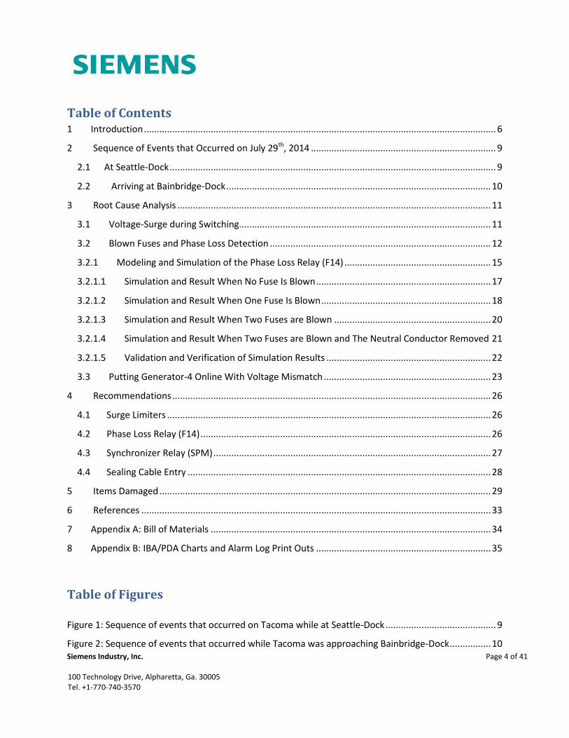
Table of Contents 1 Introduction ......................................................................................................................................... 6
2 Sequence of Events that Occurred on July 29th, 2014 ........................................................................ 9
2.1 At Seattle-Dock ............................................................................................................................... 9
2.2 Arriving at Bainbridge-Dock ....................................................................................................... 10
3 Root Cause Analysis .......................................................................................................................... 11
3.1 Voltage-Surge during Switching.................................................................................................. 11
3.2 Blown Fuses and Phase Loss Detection ...................................................................................... 12
3.2.1 Modeling and Simulation of the Phase Loss Relay (F14) ......................................................... 15
3.2.1.1 Simulation and Result When No Fuse Is Blown .................................................................... 17
3.2.1.2 Simulation and Result When One Fuse Is Blown .................................................................. 18
3.2.1.3 Simulation and Result When Two Fuses are Blown ............................................................. 20
3.2.1.4 Simulation and Result When Two Fuses are Blown and The Neutral Conductor Removed 21
3.2.1.5 Validation and Verification of Simulation Results ................................................................ 22
3.3 Putting Generator-4 Online With Voltage Mismatch ................................................................. 23
4 Recommendations ............................................................................................................................ 26
4.1 Surge Limiters .............................................................................................................................. 26
4.2 Phase Loss Relay (F14) ................................................................................................................. 26
4.3 Synchronizer Relay (SPM) ............................................................................................................ 27
4.4 Sealing Cable Entry ...................................................................................................................... 28
5 Items Damaged ................................................................................................................................. 29
6 References ........................................................................................................................................ 33
7 Appendix A: Bill of Materials ............................................................................................................. 34
8 Appendix B: IBA/PDA Charts and Alarm Log Print Outs .................................................................... 35
Table of Figures
Figure 1: Sequence of events that occurred on Tacoma while at Seattle-Dock ........................................... 9
Figure 2: Sequence of events that occurred while Tacoma was approaching Bainbridge-Dock ................ 10

Siemens Industry, Inc.
Page 5 of 41
100 Technology Drive, Alpharetta, Ga. 30005 Tel. +1-770-740-3570
Figure 3: Generator-4 PT connection .......................................................................................................... 13
Figure 4: Connection diagram of the phase loss relay (F14)....................................................................... 14
Figure 5: Generator-4 breaker trip control circuit ...................................................................................... 15
Figure 6: Simulink model of Generator-4 protection scheme .................................................................... 16
Figure 7: Connections inside F14 Relay block ............................................................................................. 17
Figure 8: Line-to-neutral voltages measured by F14 relay when all fuses are working ............................. 18
Figure 9: Line-to-neutral voltages measured by F14 relay when phase 1 fuse is blown ............................ 19
Figure 10: Line-to-neutral voltages measured by F14 relay when phases 1 and 3 fuses are blown .......... 20
Figure 11: Line-to-line voltages measured when two phases and neutral cable are not connected ......... 21
Figure 12: Generator-4 SPM connection diagram ...................................................................................... 23
Figure 13: Voltages measured by F14 and SPM relays when two fuses are blown .................................... 24
Figure 14: Front and back side views of F14 relay in a cubicle ................................................................... 26
Figure 15: Generator-3 PTs and fuses got damaged ................................................................................... 29
Figure 16: Surge limiters on Generator-4 and Generator-3 got damaged ................................................. 30
Figure 17: 5KV insulators, PT connection fingers and CT connectors got damaged cubicles ..................... 30
Figure 18: Single phase shutters and glastic board got damaged .............................................................. 31
Figure 19: High voltage cubicles of Generator-3 and Generator-4 got damaged ...................................... 31
Figure 20: Control-wire harness damaged .................................................................................................. 32
Table of Tables
Table 1: Outputs of generator protection relays .......................................................................................... 7
Table 2: Outputs of relays in Tie-1 and Tie-2 cubicles .................................................................................. 8
Table 3: Voltage measurement at the terminals of Generator-1’s F14 relay ............................................. 22
Table 5: Items damaged during July 19th incident ..................................................................................... 29
Table 6: Bill of Materials ............................................................................................................................. 34
Siemens Industry, Inc.
Page 6 of 41
100 Technology Drive, Alpharetta, Ga. 30005 Tel. +1-770-740-3570
1 Introduction
There are four identical diesel generators and two similar 4.16KV switchboards on the ferry. Generators
1 and 2 energize Switchboard 1 while generators 3 and 4 energize Switchboard 2. The two switchboards
are connected to each other by high voltage cables with a tie breaker at each end. The two switchboards
are made up of two types of cubicles connected into a uniform line-up. The two cubicle types are:
1. Cubicles equipped with SIEMENS TYPE 3AF vacuum circuit breakers. These are used in
generator, propulsion transformer, and tie cubicles.
2. Cubicles equipped with SIEMENS TYPE 81000 vacuum contact starters. These are used in the
ship service transformers, motor/generator sets, and propulsion motors excitation transformers
(i.e. in lower power applications).
Each generator connected to the switchboards is a synchronous generator rated at 3000KW, 3750KVA,
4160V, 60Hz and 900RPM. The generators are protected using the following:
1. Differential protection (ANSI/IEC 87G) – SIEMENS TYPE 7UT512 relay
2. Winding temperature protection (ANSI/IEC 49) – BASLER TYPE BE4-49
3. Over-current time delay protection (ANSI/IEC 50/51) – SIEMENS TYPE 7SJ511
4. Reverse power protection (ANSI/IEC 32) – BASLER TYPE BE4-32
5. Over-voltage protection (ANSI/IEC 59) – BASLER TYPE BE4-59
6. Under-voltage protection (ANSI/IEC 27) – BASLER TYPE BE4-27
7. Under-voltage protection(i.e. phase loss) – SIEMENS TYPE 7TU9914
8. Under/over frequency protection (ANSI/IEC 81) – BASLER TYPE BE4-81 U/O
Some of the generator protection relays listed above trip the circuit breaker isolating the generator from
the rest of the system in case of faults while some of them just send alarm signals to the Alarm and
Monitoring system. Table 1 summarizes actions of the generator protection relays.

Siemens Industry, Inc.
Page 7 of 41
100 Technology Drive, Alpharetta, Ga. 30005 Tel. +1-770-740-3570
Table 1: Outputs of generator protection relays
Disturbance
Alarm
&
Monitoring
Trip
Circuit
Breaker
Generator winding temperature alarm
(if temperature in the windings reaches 130°C) X
Generator winding temperature trip
(if temperature in the windings reaches 145°C) X
Differential relay function X X
Over-current relay function X X
Over-voltage relay function
(if voltage at the terminals of the generator
reaches 115% of its rated value)
X
Under-voltage relay function
(if voltage at the terminals of the generator
reaches 75% of its rated value)
X
Under-frequency function X
Over-frequency function X
Reverse power function X X
Under-voltage – phase loss
(if fuses at the high side of PTs are blown) X
The 4.16KV system on the ferry is a floating or isolated system (i.e. the neutral conductors of the
generators are not grounded). This is done to assure a high continuity of service even in the event of a
single line-to-ground fault. There are ground voltage relays (ANSI/IEC device number 59G) in each
switchboard that monitor ground faults. The outputs of these relays are connected to the Alarm and
Monitoring System.

Siemens Industry, Inc.
Page 8 of 41
100 Technology Drive, Alpharetta, Ga. 30005 Tel. +1-770-740-3570
In case of under-voltage on the 4.15KV buses, under-voltage relays in Tie-1 and Tie-2 cubicles will trip all
the breakers and contactors on the bus the under-voltage occurred (i.e. if under-voltage occurs on
4.15KV switchboard 1, under-voltage relay in Tie-1 cubicle will trip all breakers and contactors in
switchboard 1. Hence, removing load or generator that caused the under-voltage and the rest of the
system can continue to operate). Ground fault relays in Tie-1 and Tie-2 cubicles monitor ground fault in
the 4.16KV system.
Besides under-voltage and ground fault relays, there exists overcurrent time delay relay in Tie-2 cubicle
that trips both tie breakers in case of short-circuit on either of the switchboards and thus save the other
switchboard from a blackout. Table 2 summarizes actions of under-voltage, ground fault and over-
current time delay relays in Tie-1 and Tie-2 cubicles.
Table 2: Outputs of relays in Tie-1 and Tie-2 cubicles
Disturbance Alarm and
monitoring
Trip breakers
and contactors
Ground fault on the 4.16KV system X
Under-voltage trip X
Over-current trip (on Tie-2 only)
Trip Tie-1 and
Tie-2 breakers
Siemens Industry, Inc.
Page 9 of 41
100 Technology Drive, Alpharetta, Ga. 30005 Tel. +1-770-740-3570
2 Sequence of Events that Occurred on July 29th, 2014
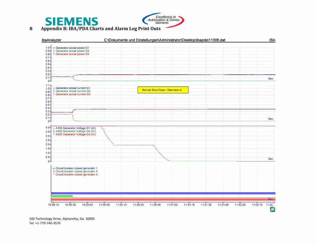
Based on data from the IBA/PDA data acquisition system, substantial damage caused to HV-cubicles of
Generator-3 and Generator-4, and minor damage caused to Excitation-Transformer AC1, the following
probable sequence of events are established. Some of the transducer-signals are filtered (up to 200
msec) and various communication channels are configured at different scan rates (up to 500 msec) at
the IBA/PDA data acquisition system. Therefore, some of the actual signal values may have looked
different than depicted on the chart-recordings [1]. Data recorded from IBA/PDA data acquisition
system is attached as Appendix B.
2.1 At Seattle-Dock
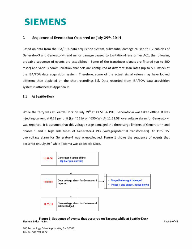
While the ferry was at Seattle-Dock on July 29th at 11:51:56 PDT, Generator-4 was taken offline. It was
injecting current at 0.29 per unit (i.e. ~151A or ~630KW). At 11:51:58, overvoltage alarm for Generator-4
was reported. It is assumed that this voltage surge damaged the three surge limiters of Generator-4 and
phases 1 and 3 high side fuses of Generator-4 PTs (voltage/potential transformers). At 11:53:15,
overvoltage alarm for Generator-4 was acknowledged. Figure 1 shows the sequence of events that
occurred on July 29th while Tacoma was at Seattle Dock.
Figure 1: Sequence of events that occurred on Tacoma while at Seattle-Dock

Siemens Industry, Inc.
Page 10 of 41
100 Technology Drive, Alpharetta, Ga. 30005 Tel. +1-770-740-3570
2.2 Arriving at Bainbridge-Dock
Approaching Bainbridge-Dock, Generator-4 was started. The high side breaker that connects Generator-
4 to the bus was closed at 12:31:00 but immediately opened due to an under-voltage trip signal from
the under-voltage relay (F11). Several under-voltage alarms were reported at switchboards 1 and 2. The
high side breaker of Generator-3 was tripped and differential trip signals were triggered by differential
relays of Generator-3 and Generator-4. Over-current time delay relays of Generator-3 and Generartor-4
registered over-current condition but since the time delay of 6 seconds didn’t expire, they didn’t issue
trip commands.
Figure 2: Sequence of events that occurred while Tacoma was approaching Bainbridge-Dock

Siemens Industry, Inc.
Page 11 of 41
100 Technology Drive, Alpharetta, Ga. 30005 Tel. +1-770-740-3570
3 Root Cause Analysis
In order to understand the root cause of the blackout, the three most important questions that need to
be answered are:
1. When Generator-4 was made offline at Seattle-Dock, there was a voltage surge and three of the
surge limiters along with two fuses of Generator-4 PTs got damaged. Why did this occur after 17
years of operation? What caused and/or contributed to the voltage surge?
2. When two of the three high side fuses of Generator-4 PTs got blown, why did the phase loss
relay not detect it? The phase loss relay is put there specifically for this purpose.
3. While arriving at Bainbridge-Dock, Generator-4 was put online. Why the HV breaker of
Generator-4 was allowed to close when its terminal voltage and frequency didn’t match that of
the rest of the system? The phase loss relay and the synchronizer relay should have prevented
the breaker from closing.
3.1 Voltage-Surge during Switching
According to IEEE.C62.48 [2], temporary over-voltage can be caused when a distribution generator and
part of the distribution network are separated. To limit over-voltage in the 4.16KV system, surge limiters
are installed on all generator and feeder cubicles. These surge limiters are designed to have an average
life span equivalent to that of the electrical installation they protect, but they progressively deteriorate
over time due to the successive over-voltage they eliminate. The exact cause of damage to the surge
limiters could not be determined due to the extensive compartment damage and limited data available
but deterioration due to high frequency of switching of the HV breaker over 17 years of operation is a
plausible reason. From tests performed on the Generator-4 breaker (on-site), the number of breaker
operations recorded is 9106.
The existing surge limiters on the ferry are of SIEMENS TYPE 3EF1048-0 (4.8KV level) and have the
following ratings:
voltage

Siemens Industry, Inc.
Page 12 of 41
100 Technology Drive, Alpharetta, Ga. 30005 Tel. +1-770-740-3570
continuous operating voltage
energy absorption capacity =
Based on the ratings of the surge arresters and the 4.16KV system (isolated system):
1. The continuous operating voltage of the surge arresters ( needs to be at least 4.16KV. During
ground fault, the surge arresters at the unfaulted lines could see line-to-line voltage level across
their terminals. Thus, their continuous operating voltage rating must be at least equal to the
line-to-line voltage rating of the system so they do not get damaged for ground faults. The
existing surge limiters on the ferry have continuous operating voltage ratings of 3.6KV, while the
line-to-line rating of the ferry is 4.16KV.
2. The energy discharge capacity of the surge arresters (
) is not high enough for generation
type application. During faults, generators keep injecting power into the system and the
arresters on generators need higher energy discharge capacity.
3.2 Blown Fuses and Phase Loss Detection
When Generator-4 was put offline at Seattle-Dock, the voltage surge damaged two of the three high
side fuses of Generator-4 PTs but the phase loss relay (SIEMENS TYPE 7TU9914) didn’t detect it.
The phase loss relay (F14 relay) in Generator-4 cubicle is an under-voltage relay that measures line-to-
neutral voltage and compares it to a set point (threshold value) to determine if a phase is lost. It takes
stepped down voltages from the Generator-4 PTs and if phase loss is detected (i.e. if measured voltage
is below the set threshold value), it sends a signal to the Alarm and Monitoring System instantaneously,
and sends a trip command to the Generator-4 breaker after a time delay of six seconds.
The way the PTs are grounded, the burden on them, and the fact that the 4.16KV system is an isolated
system, causes the line-to-neutral voltage measured by the F14 relay to be above the threshold value

Siemens Industry, Inc.
Page 13 of 41
100 Technology Drive, Alpharetta, Ga. 30005 Tel. +1-770-740-3570
when two of the three fuses burn out. Thus, the F14 relay in its current configuration can detect phase
loss when any one of the fuses or all of the fuses blow out, but it is unable to detect phase loss if two of
the three fuses burn out. Figure 3 shows connections of PTs on Generator-4, and figure 4 shows the
connection diagram of F14 relay.
Figure 3: Generator-4 PT connection

Siemens Industry, Inc.
Page 14 of 41
100 Technology Drive, Alpharetta, Ga. 30005 Tel. +1-770-740-3570
As seen from figure 4, F14 relay is powered by a 24VDC power supply and it accepts phase voltages and
the neutral as inputs. It compares each of the phase voltages (line-to-neutral) to a threshold voltage
value of 42 (voltage set value) and if the result is lower, it sends an instantaneous alarm signal, and
after six seconds, it sends a signal to trip the breaker and isolate the generator.
Currently, two normally open contacts (N.O. or A contacts) from F14 are used to send alarm and trip
signals. As shown in figure 5, the trip contact from F14 is tied in series with a normally closed contact
(N.C. or B contact) from ground-fault relay in tie-breaker 2 cubicle. Therefore, F14 will only trip the
breaker after six seconds and if there is no ground fault detected by the ground-fault relay (59G)
initially. This is done for reliability purposes (i.e. to make the generator stay online as long as possible).
In case of ground fault, the phase loss relay (which is an under-voltage relay) detects under-voltage and
interprets it as phase loss and will try to trip the breaker.
Figure 4: Connection diagram of the phase loss relay (F14)

Siemens Industry, Inc.
Page 15 of 41
100 Technology Drive, Alpharetta, Ga. 30005 Tel. +1-770-740-3570
3.2.1 Modeling and Simulation of the Phase Loss Relay (F14)
The 4.16KV system is an isolated or floating system but generator PTs are grounded at locations shown
in figure 6. To investigate the effect of the isolated system and grounded PTs with burden (load) on the
phase loss detection capability of F14 relay, the model shown in figure 6 is built using MATLAB/Simulink
software.
Figure 5: Generator-4 breaker trip control circuit
Siemens Industry, Inc.
Page 16 of 41
100 Technology Drive, Alpharetta, Ga. 30005 Tel. +1-770-740-3570
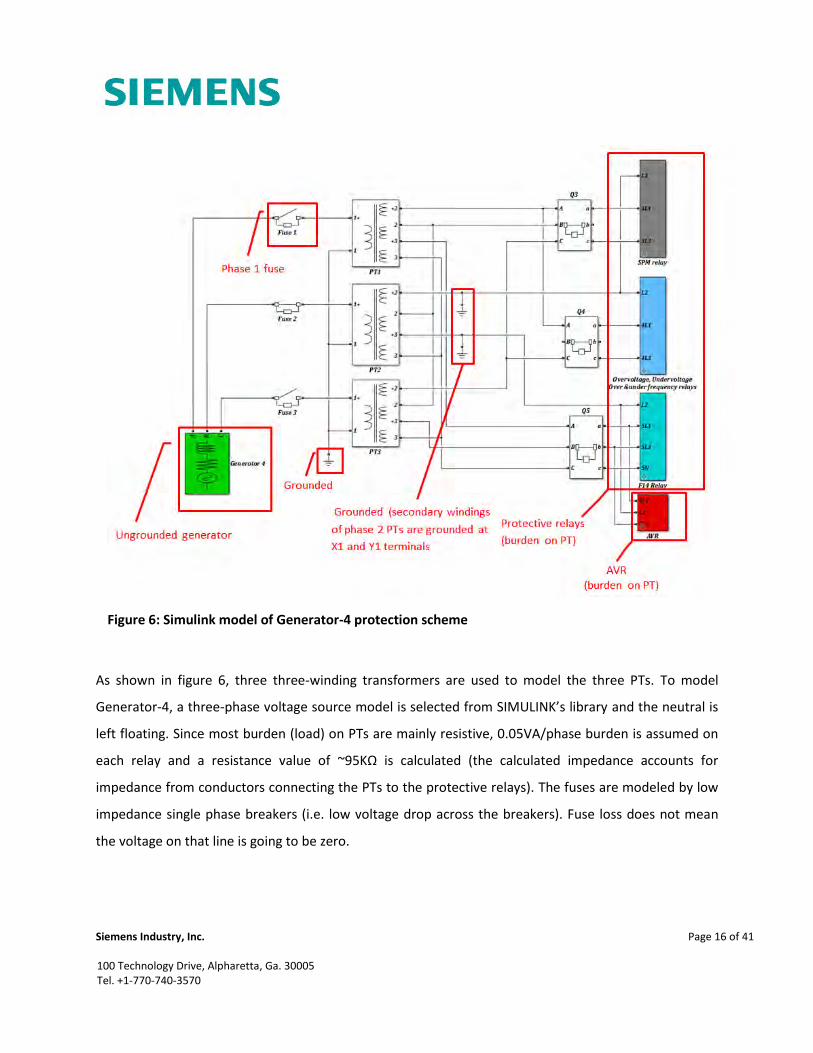
As shown in figure 6, three three-winding transformers are used to model the three PTs. To model
Generator-4, a three-phase voltage source model is selected from SIMULINK’s library and the neutral is
left floating. Since most burden (load) on PTs are mainly resistive, 0.05VA/phase burden is assumed on
each relay and a resistance value of ~95KΩ is calculated (the calculated impedance accounts for
impedance from conductors connecting the PTs to the protective relays). The fuses are modeled by low
impedance single phase breakers (i.e. low voltage drop across the breakers). Fuse loss does not mean
the voltage on that line is going to be zero.
Figure 6: Simulink model of Generator-4 protection scheme

Siemens Industry, Inc.
Page 17 of 41
100 Technology Drive, Alpharetta, Ga. 30005 Tel. +1-770-740-3570
The F14 Relay block consists of voltage measurement blocks and comparison blocks. A scope is
connected to visually display the voltage measured by the F14 measurement blocks. Double clicking the
F14 Relay block reveals the inside connection diagram of the F14 relay. Figure 7 shows the inside
connection diagram of the F14 Relay block.
3.2.1.1 Simulation and Result When No Fuse Is Blown
When the model is run with all fuses working, the expected voltage at terminals of the F14 relay is
√ (line-to-neutral) and it is well above the voltage set point (i.e. 42 ). Figure 8 shows
scope capture of voltages measured at the terminals of F14 relay when all fuses are working. It can be
seen from the figure that the measured line-to-neutral voltage of each phase is about ~98 (~69 ).
Figure 7: Connections inside F14 Relay block

Siemens Industry, Inc.
Page 18 of 41
100 Technology Drive, Alpharetta, Ga. 30005 Tel. +1-770-740-3570
3.2.1.2 Simulation and Result When One Fuse Is Blown
For this simulation, phase 1 fuse is opened and line-to-neutral voltages measured by F14 relay are
captured by the scope.
Figure 8: Line-to-neutral voltages measured by F14 relay when all fuses are working

Siemens Industry, Inc.
Page 19 of 41
100 Technology Drive, Alpharetta, Ga. 30005 Tel. +1-770-740-3570
As seen from figure 9, the line-to-neutral voltage measured by the F14 relay is almost ~98 (~69 )
for phases 2 and 3, but it is about ~9 (~6 ) for phase 1. Phase 1 voltage measured is well below
the set threshold value of 42 and the relay will trip the breaker after six seconds.
Figure 9: Line-to-neutral voltages measured by F14 relay when phase 1 fuse is blown
Siemens Industry, Inc.
Page 20 of 41
100 Technology Drive, Alpharetta, Ga. 30005 Tel. +1-770-740-3570
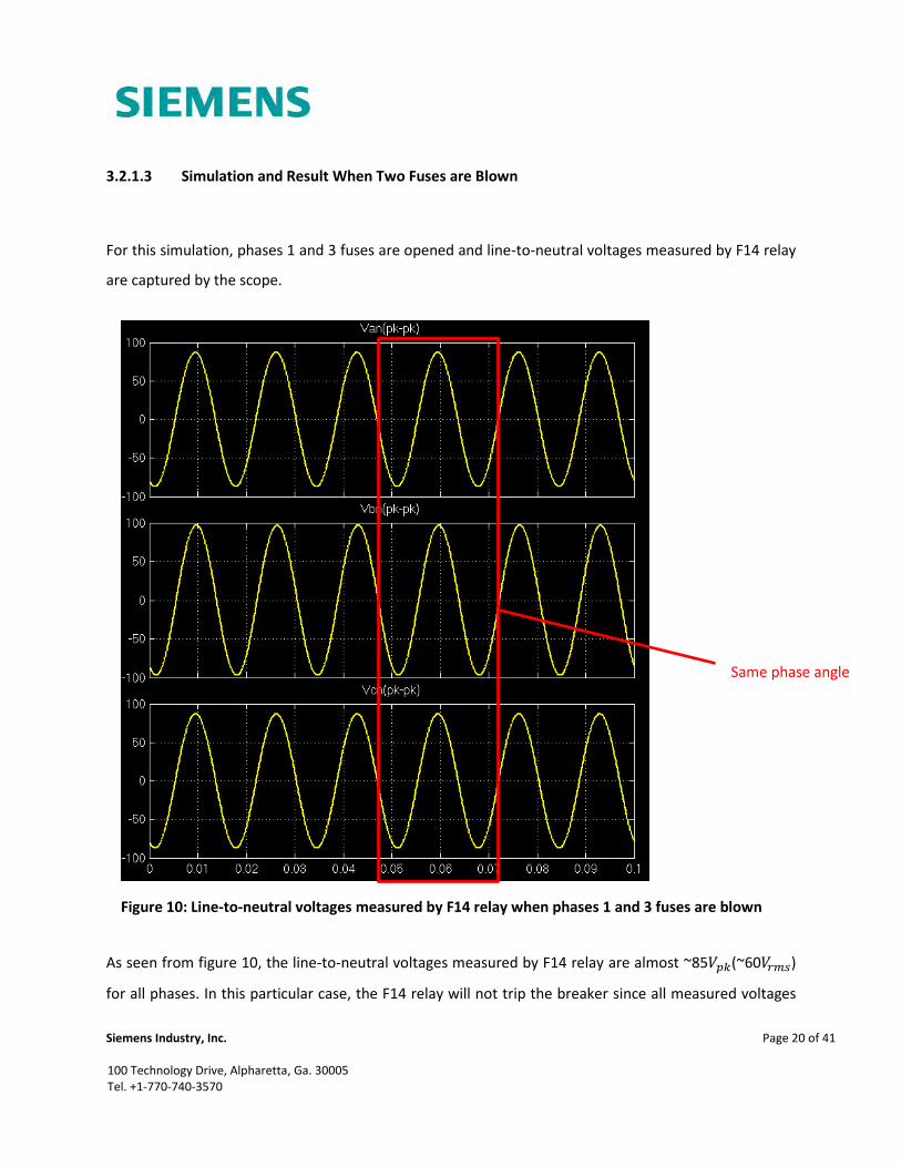
3.2.1.3 Simulation and Result When Two Fuses are Blown
For this simulation, phases 1 and 3 fuses are opened and line-to-neutral voltages measured by F14 relay
are captured by the scope.
As seen from figure 10, the line-to-neutral voltages measured by F14 relay are almost ~85 (~60 )
for all phases. In this particular case, the F14 relay will not trip the breaker since all measured voltages
Figure 10: Line-to-neutral voltages measured by F14 relay when phases 1 and 3 fuses are blown
Same phase angle

Siemens Industry, Inc.
Page 21 of 41
100 Technology Drive, Alpharetta, Ga. 30005 Tel. +1-770-740-3570
are above the threshold value of 42 . It is also observed that all measured voltages have identical
phase angles (i.e. all of them have the same phase shift as phase 2).
3.2.1.4 Simulation and Result When Two Fuses are Blown and The Neutral Conductor Removed
For this simulation, phases 1 and 3 fuses are opened and the neutral conductor is removed from
terminals of F14 relay. As shown by the scope capture, line-to-neutral measured voltages by F14 relay
when two fuses are blown and when neutral conductor removed are all less than 10
Figure 11: Line-to-line voltages measured when two phases and neutral cable are not connected

Siemens Industry, Inc.
Page 22 of 41
100 Technology Drive, Alpharetta, Ga. 30005 Tel. +1-770-740-3570
3.2.1.5 Validation and Verification of Simulation Results
Using Generator-1’s F14 relay, line-to-neutral voltages at the terminals of F14 are measured on site [1].
By supplying 47 between terminals of the PTs, and by pulling out phases 1 and 3 fuses,
voltages at the terminals of F14 are measured and recorded. Table 3 summarizes the result obtained.
Table 3: Voltage measurement at the terminals of Generator-1’s F14 relay
Applied voltage
F14 (line-to-neutral) Connected devices
Phase A Phase B Phase C
47 48.6V 46.8V 48.2V F14+AVR+Q3+Q4
47 20.6V 47.4 34.3 F14+Q3+Q4
47 0V 47.2V 0V Only F14
F14 (line-to-line)
47 7.67V 6.95V 0.73V F14+AVR+Q3+Q4
As shown in table 3, when 47V is supplied between terminals of the PTs and phases 1 and 3
fuses are pulled out, the line-to-neutral voltages measured by F14 relay are almost the same as the
supplied voltage (i.e. above the threshold value). When the neutral conductor is removed from the
terminals of F14 relay and the test is repeated, the line-to-line voltages measured at the terminals of
F14 relay are all well below the threshold value.
The reason why 47V is supplied between terminals of the PTs instead of the full line-to-line
voltage of 120V is for safety purposes (to avoid using higher voltage) and it is selected to be above the
threshold value. As seen from table 3, the voltages measured at terminals of F14 relay are different
depending on the secondary side PT breakers and whether AVR are connected or not (i.e. whether Q3
and Q4 are closed and AVR is connected or not). Under normal operations, the secondary side breakers
are closed and AVR is connected and the PTs see full burden.
Based on the results of the simulation and on-site tests performed on the F14 relay, the F14 relay is
unable detect phase loss when two of the three fuses get damaged.

Siemens Industry, Inc.
Page 23 of 41
100 Technology Drive, Alpharetta, Ga. 30005 Tel. +1-770-740-3570
3.3 Putting Generator-4 Online With Voltage Mismatch
When an offline generator is about to be put online, the synchronizer (WOODWARD TYPE SPM 9905-
001) relay compares the generator’s phase 1 phase angle against phase 1 of the 4.16KV bus and if they
don’t match within ±10° tolerance, it either speeds up or slows down the generator through the Load
Sharing and Speed Control relay. If there is phase angle match, the SPM relay sends signal to the PLC
(E200) to close the generator breaker. Figure 12 shows the connection diagram of Generator-4 SPM
relay.
As shown and discussed in section 3.2.1.3, the phase loss relay (F14) does not detect phase loss when
two of the three fuses get damaged (i.e. the line-to-neutral voltages measured at the terminals of the
Figure 12: Generator-4 SPM connection diagram

Siemens Industry, Inc.
Page 24 of 41
100 Technology Drive, Alpharetta, Ga. 30005 Tel. +1-770-740-3570
F14 relay are above the threshold value of 42 ). To investigate the line-to-ground voltage value at
the terminals of the SPM relay when two of the three fuses are blown, voltage measurement block is
added inside the SPM Relay block and the model is run. Figure 13 shows the scope capture of the
voltages measured at the terminals of the F14 and SPM relays when two fuses are blown.
Figure 13: Voltages measured by F14 and SPM relays when two fuses are blown
By F14 relay
By SPM relay

Siemens Industry, Inc.
Page 25 of 41
100 Technology Drive, Alpharetta, Ga. 30005 Tel. +1-770-740-3570
The magnitude of voltage measured by the SPM relay is well below the line-to-neutral voltage value of
~70 (as shown in figure 13) when two of the three fuses burn out. If the SPM relay model installed
on the ferry had a capability to compare voltage magnitudes besides phases, it would have caught the
voltage magnitude difference between Generator-4 PTs and PTs on the 4.16KV bus 2. It would not have
sent the “close” command to the PLC and the PLC in turn wouldn’t have closed Generator-4 breaker
with such severe voltage mismatch.

Siemens Industry, Inc.
Page 26 of 41
100 Technology Drive, Alpharetta, Ga. 30005 Tel. +1-770-740-3570
4 Recommendations
4.1 Surge Limiters
When the blackout occurred, both 4.16KV switchboards were tied together and the surge limiters on all
feeders might be stressed out. They have to be tested according to IEEE recommended practice for
surge arrester test procedures. The existing surge limiters on the feeders do not have a maximum
continuous operating voltage rating of 4.16KV (i.e. they are rated for ) Therefore, Siemens
recommends replacing the surge arresters on all feeders. The surge arresters on generators do not have
the right energy discharge ratings and they need to be replaced with surge arresters recommended for
generation type application. The following surge arrester types are recommended:
For feeders, ABB TYPE POLIM-C 4.8 LB (
For generators, SIEMENS TYPE 3EL2 006-2PC31-4NH5 (
4.2 Phase Loss Relay (F14)
The phase loss relay (SIEMENS TYPE 7TU9914) can be configured to measure line-to-line voltages [3]. As
seen from the simulation result and from the on-site test, the phase loss relay can detect any kind of
phase loss if it is configured to measure line-to-line instead of line-to-neutral voltages. Figure 14 shows
front and back side views of F14 relay in Generator-4 cubicle (low voltage cubicle).
Figure 14: Front and back side views of F14 relay in a cubicle

Siemens Industry, Inc.
Page 27 of 41
100 Technology Drive, Alpharetta, Ga. 30005 Tel. +1-770-740-3570
The preferred solution is replacing the F14 relay with a modern relay that has both phase and voltage
magnitude comparison capabilities. However, if the F14 relay were to be replaced, there is no space on
the doors of the generator cubicles (figure 14) and it would need lots of rewiring. Therefore, Siemens
recommends reconfiguring the F14 relay by removing the neutral conductor from its terminal and
changing the voltage set value (threshold value) to 64V. This was verified at Siemens Alpharetta facility
as follows:
1. Power the F14 relay by supplying
2. Adjust the voltage set to 64V by opening all the switches on the dip switch except for switch
number 3 and 7 (i.e. 30V + ∑( )
3. Connect three phase 120 voltage supply to F14 terminal no. 1,2 and 3
4. Supply + to F14 terminal no. 10 and 14
5. Remove phase 1 supply from F14 terminal no. 1
6. Check for instantaneous voltage change between F14 terminal no. 14 and 15
7. Check voltage change between F14 terminal no. 10 and 11 after 6s time delay
8. Repeat steps 5 to 7 for single phase loss detection
9. Repeat steps 5 to 7 for two phase loss detection
10. Repeat steps 5 to 7 for three phase loss detection
Because of the impedance of the cables connecting PTs to F14 on the ferry, the set voltage value of 64V
has to be field adjusted.
4.3 Synchronizer Relay (SPM)
The SPM relay model installed on Tacoma (WOODWARD 9905-001) checks only phase match between
two lines but does not check voltage magnitude match. If this relay had the capability to check voltage
mismatch, the Generator-4 breaker would not have been allowed to close with severe voltage mismatch
with the 4.16KV system while Tacoma was approaching Bainbridge-Dock. Therefore, Siemens

Siemens Industry, Inc.
Page 28 of 41
100 Technology Drive, Alpharetta, Ga. 30005 Tel. +1-770-740-3570
recommends replacing the SPM relay with a WOODWARD SPM 9905-003 model that has the capability
of checking both phase and voltage match (5% tolerance) between two lines.
4.4 Sealing Cable Entry
Cable entry cover plates are missing in both switchboards. According to current ANSI/IEEE C37.20.7 [4]
and IEC 61641 [5] testing guides for internal arc faults:
1. Cubicles should have correctly secured doors and their covers should not open
2. Internal arc should not migrate to other compartments
Siemens recommends sealing these cable entries and verifying proper pressure venting.

Siemens Industry, Inc.
Page 29 of 41
100 Technology Drive, Alpharetta, Ga. 30005 Tel. +1-770-740-3570
5 Items Damaged
The following table summarizes the items that got damaged during the July 29th incident.
Table 4: Items damaged during July 19th incident
Generator-4 Generator-3 Excitation-transformer AC1
Two PT fuses (phase 1 and phase 3) Three PT fuses One surge limiter (phase 1)
Three surge limiters Three surge limiters One HV fuse (phase 1)
Insulators, copper-bars, and metal
parts
Insulators, copper-bars, and
metal parts
High voltage cables Three PTs
Cubicle partitions High voltage cables
Control-wire harness Cubicle partitions
Control-wire harness
Figure 15: Generator-3 PTs and fuses got damaged

Siemens Industry, Inc.
Page 30 of 41
100 Technology Drive, Alpharetta, Ga. 30005 Tel. +1-770-740-3570
Figure 16: Surge limiters on Generator-4 and Generator-3 got damaged
Figure 17: 5KV insulators, PT connection fingers and CT connectors got damaged cubicles
Siemens Industry, Inc.
Page 31 of 41
100 Technology Drive, Alpharetta, Ga. 30005 Tel. +1-770-740-3570
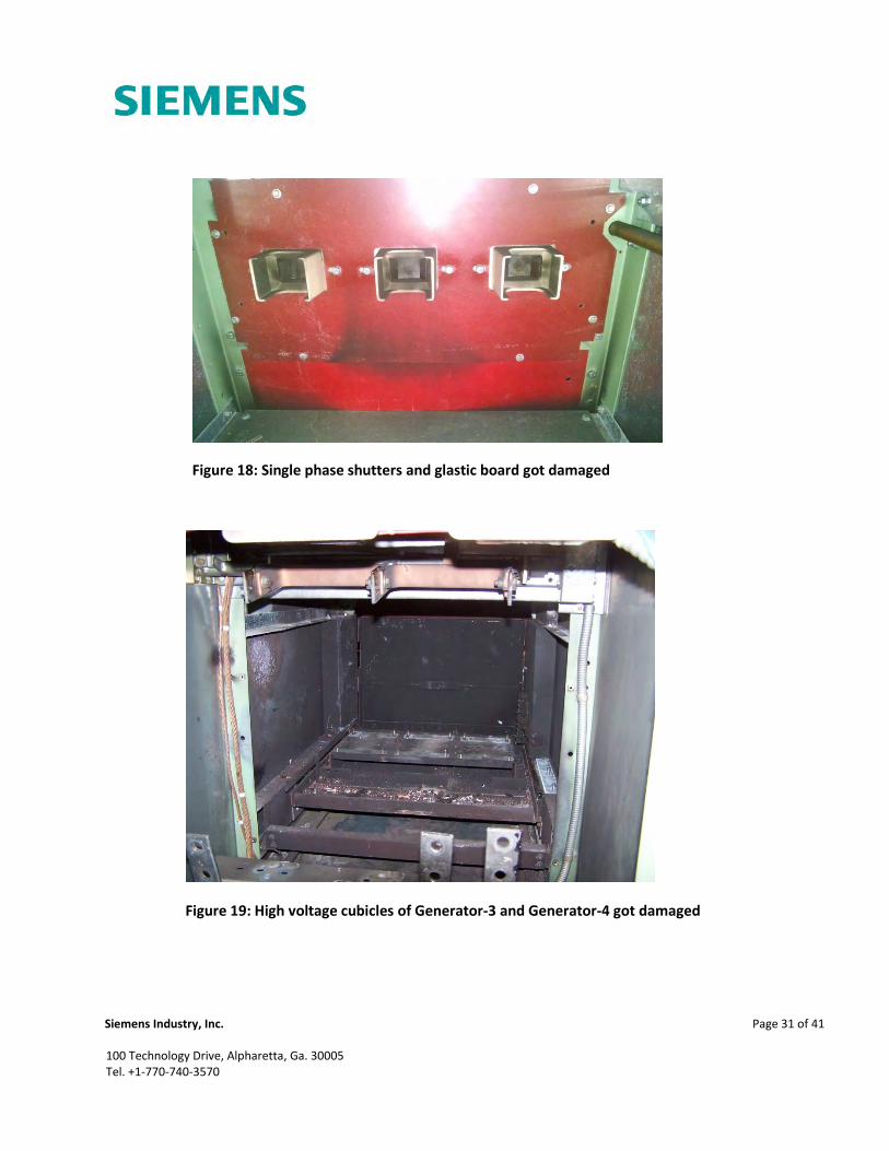
Figure 18: Single phase shutters and glastic board got damaged
Figure 19: High voltage cubicles of Generator-3 and Generator-4 got damaged

Siemens Industry, Inc.
Page 32 of 41
100 Technology Drive, Alpharetta, Ga. 30005 Tel. +1-770-740-3570
Figure 20: Control-wire harness damaged

Siemens Industry, Inc.
Page 33 of 41
100 Technology Drive, Alpharetta, Ga. 30005 Tel. +1-770-740-3570
6 References
[1]. Schuckert, Fritz, “Washington-State-Ferry, WSF “Tacoma” Investigation of “July-29th” Incident,
Report No. 1914, August 08, 2014
[2]. IEEE Std C62.48, IEEE Guide for Interactions Between Power System Disturbances and
Surge- Protective Devices
[3]. Siemens Relay Manual, “Solid-state AC Over/Undervoltage Relay 7TU99”, R 1.3, 1994
[4]. IEEE Std C37.20.7, IEEE Guide for Testing Metal-Enclosed Switchgear Rated Up To 38KV For Internal
Arcing Faults
[5]. IEC TR 61641:2014, Enclosed Low-Voltage Switchgear and Assemblies – Guide for Testing Under
Conditions of Arcing due to Internal Fault

Siemens Industry, Inc.
Page 34 of 41
100 Technology Drive, Alpharetta, Ga. 30005 Tel. +1-770-740-3570
Excellence in Automation & Drives:
Siemens
7 Appendix A: Bill of Materials
Table 5: Bill of Materials
No. Item
1 Disconnect fingers
2 5KV red insulators
3 Connecting frame
4 6KV surge arresters (generator application)
5 6KV surge arresters (non-generator application)
6 Surge arrester mounting brackets
7 Voltage transformers
8 High voltage fuse
9 Fuse clips
10 Synchronizer (SPM relay)
11 Red glastic board
12 Red glastic board
13 Single phase shutters
14 Rear panel cover brackets
15 Braded uninsulated copper wire
16 Uninsulated wire lugs
17 Clean tubing
Siemens Industry, Inc.
Page 35 of 41
100 Technology Drive, Alpharetta, Ga. 30005 Tel. +1-770-740-3570
Excellence in Automation & Drives:
Siemens
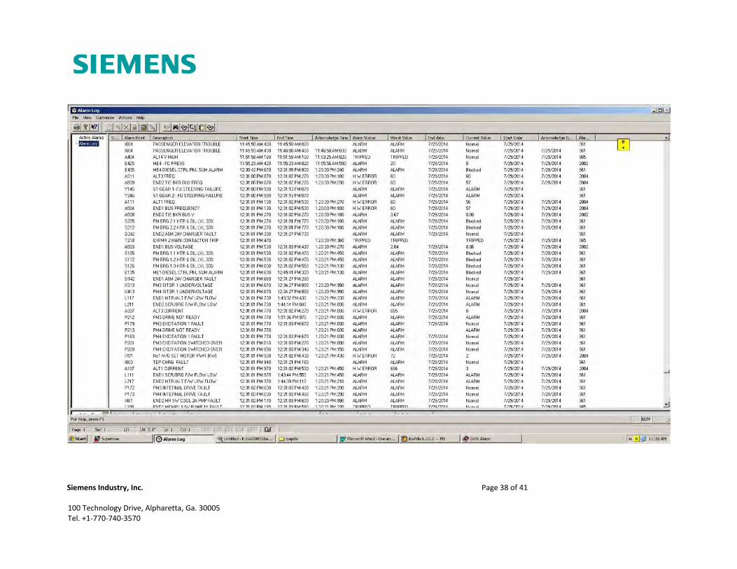
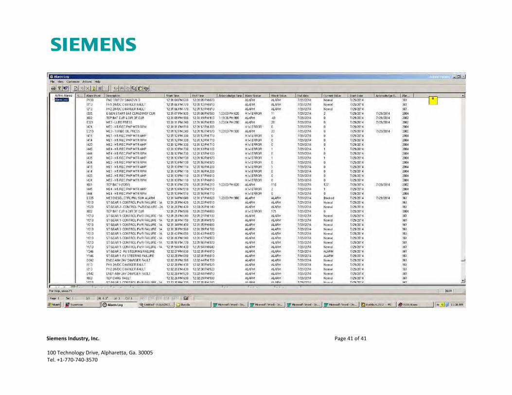
8 Appendix B: IBA/PDA Charts and Alarm Log Print Outs

Siemens Industry, Inc.
Page 36 of 41
100 Technology Drive, Alpharetta, Ga. 30005 Tel. +1-770-740-3570

Siemens Industry, Inc.
Page 37 of 41
100 Technology Drive, Alpharetta, Ga. 30005 Tel. +1-770-740-3570
Siemens Industry, Inc.
Page 38 of 41
100 Technology Drive, Alpharetta, Ga. 30005 Tel. +1-770-740-3570

Siemens Industry, Inc.
Page 39 of 41
100 Technology Drive, Alpharetta, Ga. 30005 Tel. +1-770-740-3570

Siemens Industry, Inc.
Page 40 of 41
100 Technology Drive, Alpharetta, Ga. 30005 Tel. +1-770-740-3570
Siemens Industry, Inc.
Page 41 of 41
100 Technology Drive, Alpharetta, Ga. 30005 Tel. +1-770-740-3570