electricalpartmanuals€¦ · the 7sj511 is a microprocessor based, three-phase and ground,...
TRANSCRIPT

SIEMENS Product Bulletin SG8021 Page 1 November 1994
17SJ511 Numerical Overcurrent Protection
Features o Microprocessor-Based Teonnology o Fully Numerical Design o 3-Phase and Ground Overcurrent
Protection - Instantaneous (50/50N) - Definite Time (51/51 N) - Inverse Time (51/51 N)
o Breaker Failure Protection (50BF) o Reverse Interlock Bus Protection o Nonvolatile Memory for Settings,
Event Logs, and Targets o Programmable Binary Inputs,
LEOs, Signal and Trip Relays o Four Independent Setting Groups o Real Time Clock o Circuit Breaker Operations Counter o Accumulated Circuit Breaker
Interrupted Current (per pole) o Circuit Breaker Trip Test o Two (2) Serial Ports o IEC 870-5 Communication Stan
dard o Waveform Capture (20 samples
per cycle) o Target Data o Operations Event Log o Current Metering Function (online) o Isolated DC to DC Power Supply o Self-Monitoring o Draw Out Construction
Description The 7SJ511 is a microprocessorbased, three-phase and ground, overcurrent relay. The user can select definite time or inverse time protection. An additional high-set element
Figure 1. 7SJ511 Operator Panel
can be set as instantaneous or time delayed. Phase and ground settings are independent.
All analog current inputs are isolated with internal transformers. High frequency components are removed by anti-aliasing fihers. The inputs are sampled 20 times per cycle and converted to digital signals. Reliable, field-proven, numerical algorithms process the protection functions that include breaker failure protection and reverse interlocking.
As shown in Figure 1 above, the relays have a buih-in numeric key pad and a 32-character liquid crystal display for setting the relay, monitoring measured and calculated values, and readout of various logs. LEOs are provided on the front for quick display of relay status and target indication.
�0
Two serial communication ports are provided: one on the front for local connection of a personal computer for use by an operator, and, optionally, one on the back for connection to a substation control system.
The 7SJ511 has 4 current inputs, 2 optically isolated binary inputs, 2 trip relays, 4 signal relays and 8 LEOs. The ability to program the inputs, outputs and LEOs provides the user flexibility to configure the relay to his specific requirements. Figure 2 shows the 7SJ511 block diagram.
The relays are suitable for either panel or rack mounting and come in either a flush or surface mounting case. External connections are made on the rear for the flush mounting or on the front for the surface mounting. Screw terminals are provided which accept #1 0 ring lugs for current
www . El
ectric
alPar
tMan
uals
. com

SIEMENS Product Bulletin SG8021 Page 2 November 1994
17SJ511 Numerical Overcurrent Protection
circuits and #8 ring lugs for all other Figure 2. 7SJ511 Block Diagram circuits. ��:..:..... _ ___::...:_: _____ _::. _______________ __,
Draw out construction provides easy Power System
removal and replacement of the relay. L1 l2 l3
All CT inputs are automatically shorted and all other circuits are disconnected.
Application The 7SJ511 relay can be used as primary protection for distribution or subtransmission lines and as backup protection for transmission lines, transformers, and generators.
The 7SJ511 can also be applied as a breaker failure relay initiated by either internal or external trip signals.
For radial distribution substations, bus protection can be implemented using the reverse interlock capability.
Waveform capture can be initiated by trip command, relay pickup, or external command. Up to 150 cycles of data, including 5 prefault cycles, are available. The resolution is 20 samples per cycle (0.83 ms at 60 Hz).
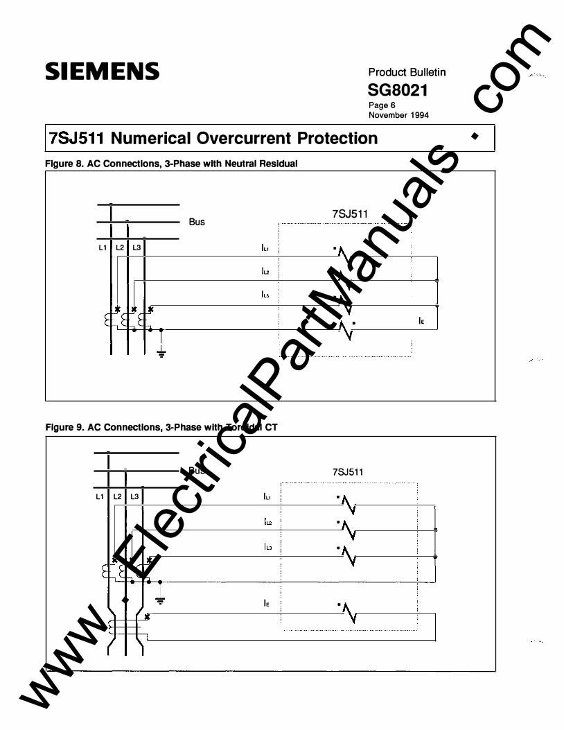
Phase and ground settings are independent. Ground current can be obtained from a separate toroidal CT or from the neutral connection of the three phase CTs.
The 7SJ511 relay stores 4 separate groups of settings. With the Parameter Changeover function, the relay, while not in pick-up, can change its operating settings to another group that accommodates new or changing system conditions. Parameter Changeover can be activated through the operator panel or front serial port, or by a binary input.
Operating Principles Digitized input values are compared against the programmed protection
2 {' Binarv , lnoots • (programmatM) :
Power Supply ; f0C71--�
settings. If the values are above the specified limits, programmed output devices are activated. External control of all protection functions is available through the binary inputs.
Overcurrent Protection The measured values obtained from the current inputs are compared against the programmed overcurrent settings. When the limits are exceeded, a programmed time delay is started. If the fault condition is still present at the expiration of the time delay, the specified trip relays, LEOs, or other output devices are activated. Pick-up values and time delays can be specified separately for phases and ground.
Both definite and inverse time protection elements are provided. The following inverse time characteristics
MUX
14-----+-- c!':a51��.., L.,_ _ _J
are available:
ANSI Inverse ANSI Short Inverse ANSI Long Inverse ANSI Moderately Inverse ANSI Very Inverse ANSI Extremely Inverse ANSI Slightly Inverse IEC Normal Inverse IEC Very Inverse IEC Extremely Inverse
In addition, an independent high-set overcurrent element for use as an instantaneous or time delayed trip is available.
Breaker Failure Protection After a circuit breaker has been signalled to trip, the breaker failure protection function can be activated to check for successful operation of
www . El
ectric
alPar
tMan
uals
. com
SIEMENS Product Bulletin SG8021 Page 3 November 1994
17SJ511 Numerical Overcurrent Protection
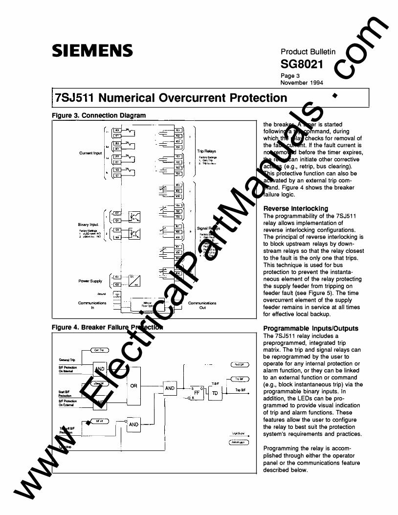
Figure 3. Connection Diagram
Currant Input
Power Supply
Corrm.micalions In
Figure 4. Breaker Failure Protection
GonoraJTrip Blfl'n>ledion On lnlomal
Slartlllf PIOl«:tion Blfl'n>ledion On Ex1omal
Tum oft Blf Prottdion
Trip Relays
FaetlrySenngl 1 GenT� 2 Tl1)1>>1e:.>
Signal Relays
FactlrySennga 1 Gen Hu.Jt 2 FakXe Zl
FaikXellymm 3. Fe.UtLt b>
H!LUl2b> FatHL3b>
4 Gen Ti1)
Comm.onicalions Out
the breaker. A timer is started following a trip command, during which the relay checks for removal of the fault current. If the fault current is not removed before the timer expires, the relay can initiate other corrective actions (e.g., retrip, bus clearing). This protective function can also be activated by an external trip command. Figure 4 shows the breaker failure logic.
Reverse Interlocking The programmability of the 7SJ511 relay allows implementation of reverse interlocking configurations. The principal of reverse interlocking is to block upstream relays by downstream relays so that the relay closest to the fault is the only one that trips. This technique is used for bus protection to prevent the instantaneous element of the relay protecting the supply feeder from tripping on feeder tau� (see Figure 5). The time overcurrent element of the supply feeder remains in service at all times for effective local backup.
Programmable Inputs/Outputs The 7SJ511 relay includes a preprogrammed, integrated trip matrix. The trip and signal relays can be reprogrammed by the user to operate for any internal protection or alarm function, or they can be linked to an external function or command (e.g., block instantaneous trip) via the programmable binary inputs. In addition, the LEOs can be programmed to provide visual indication of trip and alarm functions. These features allow the user to configure the relay to best suit the protection system's requirements and practices.
Programming the relay is accomplished through either the operator panel or the communications feature described below.
www . El
ectric
alPar
tMan
uals
. com

SIEMENS Product Bulletin SG8021 Page 4 November 1994
17SJ511 Numerical Overcurrent Protection
Self-Checking The 7SJ511 relay incorporates comprehensive monitoring functions which cover both hardware and software. Plausibility checks on the currents monitor the external CT circuits. Detection of a failure will block the relay and provide an alarm contact output. In some cases, an LED indication is available.
Hardware The relay monitors the auxiliary and internal reference voltages, AID converter, trip circuits and memory modules.
The internal DC voltages are monitored. If the voltages deviate outside the permissible limits, the protection functions are blocked, and an alarm is signaled. The relay can withstand temporary loss of the supply voltage for up to 50 milliseconds with input of 11 0 volts and above.
The trip relays are controlled by two command channels and one release channel. As long as no protection elements have picked up, the central processor checks the command channels for availability. This is a cyclic check where the channels are excited in sequence and the output signal changes are monitored. If the feedback signal changes to a low level, a fault in a channel or a relay coil is indicated. In this case, the command output is blocked and an alarm is signaled.
The complete current circuit from the CTs to the AID converters are monitored for problems in any part. The digitized sum of the four converter outputs must always be zero. User settable value for the summation factors provide compensation for for CT performance errors.
Figure 5. Reverse Interlocking
�fau�isat 0 I. Tr1Jpingtime-TI
T1<T2<T3
Tr1;t Trip
To detect interruptions or short circuits in the external CT circuits (transformers and connections), the system currents are checked for symmetry. During normal operation the currents are approximately symmetrical. If the amount of asymmetry exceeds a user settable threshold, an alarm is signaled. This checking is suspended any time a protection element picks up.
Software The memory modules are checked through a cyclic checksum process, which ts compared to the stored checksum.
A watchdog timer is provided for continuous monitoring of the program sequence. It will reset the processor in the event of a processor failure or if the program falls out of step. Additional plausibility checks are per-
fffau�isat 0 I. Tr1Jpingtime-T2 2. Bacl<up time • T3 3. 50 is blocked
Trip Trip
formed to detect faults in the program processing caused by interference. If these faults are not eliminated after three reset attempts, the relay will take itself out of service and activate the alarm contact and LED.
Operational Values The rms values of phase and neutral currents are available from the front panel LCD or the serial interfaces. Two values may be continuously dislayed on the LCD during normal operation.
Fault Data The relay stores fault target information for the last three faults. The time that the fault occurred, the element that detected the fault, and the value of the fault current are provided for each record. All of this data is stored in nonvolitile memory.
www . El
ectric
alPar
tMan
uals
. com

SIEMENS Product Bulletin SG8021 Page 5 November 1994
17SJ511 Numerical Overcurrent Protection
In addition, the relay can be programmed to display two lines of fault information in the LCD whenever a protection element picks up. LEOs programmed to indicate pickup and/or trip events can be set to retain the indications until acknowledged by an operator.
Waveform Capture The relay will record the fault waveforms for the last fault. The maximum record length is 150 cycles with a sampling rate of 20 samples per cycle. The record begins 5 cycles before pickup and can extend up to 145 cycles after pickup. An example of the captured data as it can be displayed with appropriate software is shown in Figure 6.
Waveform capture can be initiated three ways: (1) internal fault detection, (2) internal trip, or (3) external command via a binary input.
Communications An RS-232-C serial interface on the relay's operator panel (see Figure 1) allows you to connect the relay to any personal computer. The Siemens DIGSI® software package, provided with the relay, allows the user to reconfigure the relay, change settings, and retrieve data.
There also is a optional wire (RS-232-C subset) or fiber optic serial interface on the back of the unit, which can be used for online communications with a remote or local substation control or monitoring system.
Figure 6. Waveform Capture Fault n .. ber •••••••• : 399 Feeder 1 Fr, 03/19/93 12:50
I .. x• 8.46 In (Peak value)
I I I I I I I I I I I I
I-
I I I I I I I I I I I I
"�1tAJ'· . 'I ;- r"l' '..,. t t ;- ;- t ;- 1
E I ' " �LL·-1--t -;1--+-1 -;1-�: -11--+-1 -11--+-1 -11--+-1 -11--+-1 -11--+-1 -;1........--ll
Scale 10 •s . Ll . -·� • • 80 I I I
Figure 7. 7SJ511 One Line Diagram
3Y
I I I I I I +127
M = Metering C = Communications BF = Breaker Failure
www . El
ectric
alPar
tMan
uals
. com
SIEMENS Product Bulletin SG8021 Page 6 November 1994
17SJ511 Numerical Overcurrent Protection
Figure 8. AC Connections, 3-Phase with Neutral Residual
Bus 7SJ511
L1 L2 L3 lu •
ll2 •
•
•
Figure 9. AC Connections, 3-Phase with Toroidal CT
Bus 7SJ511
L1 L2 L3 lu •
•
•
le •
c I
le
www . El
ectric
alPar
tMan
uals
. com

SIEMENS Product Bulletin SG8021 Page 7 November 1994
17SJ511 Numerical Overcurrent Protection
Technical Data - Relay Specifications
Measuring circuits
Power system DC power supply via integrated DC /DC converter
Trip relays
Signal/failure relays
Binary inputs
Serial interfaces
Rated current I" Rated frequency f" Burden at I"= 1 A Burden at I"= 5 A
Overload capability: - Thermal (rms)
- Dynamic (impulse)
Rated voltage V "" (VDC) 24/48 6 0/110/125 220/250
Ripple, peak-to-peak
Power consumption -Quiescent - Energized
Loss of DC supply ride-through
Number of relays Contacts per relay Switching capacity
Switching voltage Permissible current
Number of signal relays Number of failure relays Contacts per relay Switching capacity
Switching voltage Permissible current
Number of inputs Operating voltage Current consumption
Operator interface (front port) - Connection
-Transmission speed
MAKE BREAK
MAKE BREAK
1 A or 5 A 50 Hz/60 Hz (programmable) Approx. 0.1 VA per phase Approx. 0.2 VA per phase
100 x I" for s 1 s 1 ox I" for s 10 s 4 x I" continuous
250 x I" for 1/2 cycle (peak value)
Operatjng range V" (VDC) 19 to 56
48 to 144 176 to 288
s 12% at rated voltage s 6% at the limits of the voltage ranges
Approx. 7 W Approx. 11 W
�50 ms at V"� 110VDC
2 2 form A 1000WNA
30 WNA 250 V 5 A continuous, 30 A for 0.5 seconds
4 1 1 forme 20WNA 20WNA 250 V 1 A
2 24 VDC to 250 VDC Approx. 2.5 mA, independent of operating voltage
Non-isolated 25-pin connector on the front panel, providing an EIA RS-232-C (ISO 211 0) interface for connection to a personal computer
1200 bps as delivered max. 38400 bps; min. 1200 bps
www . El
ectric
alPar
tMan
uals
. com

SIEMENS Product Bulletin SG8021 Page 8 November 1994
17SJ511 Numerical Overcurrent Protection
Technical Data - Relay Specifications (cont.) Serial interfaces (cont.)
Rear port interface - Standards
-Transmission speed
-Hamming distance
- Connection - Wire
Transmission distance Test voltage
-Connection - Fiber Optic
Optical wave length Permissible line attenuation
Transmission distance Normal signal position
Weight In housing for flush mounting In housing for surface mounting
Isolated Similar to CCITT V.24N.28, EIA RS-232-C, IEC 87D-5 Protocol DIN 19244 9600 bps as delivered max. 19200 bps; min. 4800 bps
d=4
At the housing terminals; 2 core pairs, with individual and common shields Max. approx. 0.6 mi (3280 It) (1 000 m) 2 kV with rated frequency for 1 min
Integrated F-SMA connector for direct optical fiber connection, e.g. glass fiber; 62.511 251-lm 820nm Max. 8 dB Max. 1 .2 mi (2 km) Sellable; factory setting: "light off"
17.51b (8.0 kg) 14.51b (6.5 kg)
Technical Data- System Specifications (Standards: ANSI C37.oo.o. C37.90.1, C37.90.2; IEC 255-5, 255-6)
Insulation tests (ANSI C37.90.0; IEC 255-5) High voltage test (routine test) 2 kV (rms), 50/60Hz, 1 min; alt. 2.8 k V DC, 1
min
Impulse voltage test (type test) 5 kV (peak); 1 .2/ 50 11s; 0.5 J; 3 positive and 3 negative shots at intervals of 5 s
Disturbance tests High frequency test (type test) 2.5 kV (peak); 1 MHz; 't = 15 ms; 400 shots per
s for 2 s - ANSI C37.90.1; IEC 255-22-1 class Ill
Electrostatic discharge test (type test) 8 kV (peak); 5/30 ns; 1 o positive discharges -IEC 255- 22-2 class Ill
Radiated electromagnetic fields (type test) 68, 151, or 450 MHz - IEC 255-22-3 class Ill test with walkie-talkie 25 MHz - 1 GHz; 10 V /m - ANSI C37.90.2,
C37.90.2
Fast transients (type test) 2 kV (peak); 5150 ns; 5kHz; 4 mJ per shot -IEC 41 B (CO) class Ill 5 kV; 10/150 ns - ANSI C37.90.1
Machanical stress tests During operation 1oHz to 60Hz: 0.035 mm amplitude
60 Hz to 500 Hz: 0.5 g acceleration
During transport 5Hz to 8Hz: 7.5 mm amplitude 8 Hz to 500 Hz; 2 g acceleration
www . El
ectric
alPar
tMan
uals
. com

SIEMENS Product Bulletin SG8021 Page 9 November 1994
17SJ511 Numerical Overcurrent Protection
Technical Data • System Specifications (cont) Climatic tests
Permissible ambient temperature during - Operation -20° C to +55° C ( -4° F to + 1 3 1 ° F) - Storage -25° C to +55° C (-13° F to +1 31° F)
Humidity 95% non-condensing
Technical Data • Definite Time Overcurrent Protection (50/SO N, 51/51 N)
Setting range/steps Overcurrent pickup setting, 1/IN 0.1 o to 25.00 (steps 0 .01) (phases and neutral)
High-set overcurrent pickup setting, Ill" 0.1 o to 25.00 (steps 0.01) (phases and neutral)
Delay time setting 0.00 s to 60.00 s (steps 0.01 s) or infinite
Times Pickup time with:
2 x setting value, w/o meas. repetition Approx. 33 ms 2 x setting value, with meas. repetition Approx. �0 ms 5 x setting value, w/o meas. repetition Approx. 25 ms 5 x setting value, with meas. repetition Approx. 40 ms
Reset time Approx. 50 ms
Overshot time Approx. 35 ms
Reset ratio Approx. 0.95
Tolerances Pickup value ± 3% of setting value
Delay time ± 1% of setting value or 10 ms
Influence variables Power supply in range: 0.8 � VHNHN � 1 . 1 5 � 1 %
Temperature in range: oo c �e..,o� 40° c � O.So/o/1 oo C
Frequency in range: 0.98 � f/fN � 1 .02 � 1.0% 0.95 � f/fN � 1 .05 � 2.5%
Harmonics: Up to 10% of 3rd � 1 % Up to 1 0% of 5th � 1 %
www . El
ectric
alPar
tMan
uals
. com

SIEMENS Product Bulletin SG8021 Page 10 November 1994
17SJ511 Numerical Overcurrent Protection
Technical Data • Inverse Time Overcurrent Protection (51/51 N)
Setting range/steps
Trip Time Characteristics
Tolerances
Influence variables
Overcurrent pickup setting, IP =Ill" (phases and neutral)
Time multiplier setting, TP
ANSI IEC 255-3 - Inverse - Normal inverse -Short inverse - Very inverse - Long inverse - Extremely inverse - Moderately inverse - Very inverse - Extremely inverse - Slightly inverse
Pickup threshold
Pickup valuP
Delay time for 2 � 1/IP � 20 if: TP = 1 Tp .. 1
Power supply voltage in range 0.8� V"N"" � 1.15
Temperature in range o• C � e AMB � 40• C
Frequency in range 0.95 � 1/f" � 1.05
Technical Data • Breaker Failure Protection (SOBF)
Setting range/steps Pickup setting, VI" (phases and neutral)
Delay time setting, T BF
Times Pickup time with:
Internal start External start
Reset time
Tolerances
Pickup value
Delay time
0.1 0 to 4.00 (steps 0.01)
0.05 s to 3.20 s (steps O.Q1 s) or infinite
1.1 lp
± 5% of setting value
± 5% of setting value Additional ± 2% or at least ± 30 ms
�1%
� 0.5o/o11 o• C
�8%
0.1 0 to 4. 00 (steps 0.01)
0.06 s to 60.00 s (steps 0.01 s) or infinite
Included in overcurrent time Approx. 50 ms
Approx. 50 ms
± 3% of setting value
± 1% of setting value or at least ± 20 ms
www . El
ectric
alPar
tMan
uals
. com

SIEMENS Product Bulletin SG8021 Page 11 November 1994
17SJ511 Numerical Overcurrent Protection
Technical Data - Ancillary Function Specifications Operational measured values
Line currents ll1, ll2, IL3' IE - Measurement range 0% to 240% of IN - Tolerance ±2%of IN
Measured value plausibility checks Sum of currents ll1, ll2, IL3' IE
Steady· state measured value supervision
Current unbalance lma.'lm•n > symmetry factor as long as I > 11m,,
Waveform capture
Recording time - Front port 5 cycles before fault; up to 145 cycle after fault
-Rear port 3 cycles before fault; up to 30 cycles after fault
Sampling rate 20 per cycle
Target log
Fault event data storage - Maximum no . of faults 3 most recent - Maximum no. of events per fault 80
- Sequence /display resolution 1 ms
Event log
Operational data storage - Maximum no. of events 50 most recent -Sequence resolution 1 ms - Display resolution 1 min
Real time clock
Accuracy ±0.01%
Standby power - Type Internal lithium battery -Life 5 years
www . El
ectric
alPar
tMan
uals
. com

SIEMENS Product Bulletin SG8021 Page 12 November 1 994
17SJ511 Numerical Overcurrent Protection
Ordering Information
7SJ511r·
1 A 1
Model Number Rated Current (50 or 60 Hz)
�S_A---------------------------------------------5 Power Supply Input Voltage
24,48 VDC 60, 110, 125 VDC 220,250 VDC Mounting Construction
Surface (projection) mounting Panel flush mounting Panel flush mounting with screw terminals
Options
Without real time clock and parameter changeover With real time clock and parameter changeover
Serial system interface (rear port)
Without interface With isolated electrical interface With fiber optic interface
2 4 5
B c G
A1
0 1
- 0
A B c
www . El
ectric
alPar
tMan
uals
. com

SIEMENS Product Bulletin SG8021 Page 13 November 1994
17SJ511 Numerical Overcurrent Protection
Dimensions- Flush Mounting (inches)
9.65±0.04 ' 10.07 ±0.01 9.61
m--------�-1 Switchboard cutout
Front view
r---- 5.90� 1�571
-�1
1-D D
�� 10.47 0 c
� 9
�� -''-- 0 0
Rear View
Reset and paging buttons
Side View
www . El
ectric
alPar
tMan
uals
. com

SIEMENS Product Bulletin SG8021 Page 14 November 1 994
17SJ511 Numerical Overcurrent Protection
Notes:
www . El
ectric
alPar
tMan
uals
. com

SIEMENS Product Bulletin SG8021 Page 15 November 1994
17SJ511 Numerical Overcurrent Protection
Notes:
www . El
ectric
alPar
tMan
uals
. com

SIEMENS
SG8021
©1994 Siemens Energy & Automation, Inc.
Siemens Energy & Automation, Inc. Electrical Apparatus Division Protection & Control Group P.O. Box 29503 Raleigh, NC 27626-0503 Tel: (919) 365-6600 Fax: (919) 365-2552
www . El
ectric
alPar
tMan
uals
. com