rotor rub
DESCRIPTION
rub in rotorTRANSCRIPT

Journal of Sound and ~bration (1987) 113(3), 529-545
NON-LINEAR TRANSIENT ANALYSIS OF
ROTOR-CASING RUB EVENTS
F. K. CltoY AND J. PADOVAN
Department of Mechanical Engineering, The University of Akron, Akron, Ohio 44325, U.S.A.
(Received 31 August 1985, and in revised form 15 April 1986)
The problem of the non-linear dynamics of rotor/casing rub interactions in rotating equipment is investigated. Specifically, a non-linear analytical rotor casing rub interaction simulation is solved. This yields insights as to the interrelationship between rub force histories, energy levels, rub duration, incidence separation angles, and backward whirl initiation, as well as the overall rotor orbit during successive rubs. Special attention is also given to determine the effects of casing stiffness, friction coefficient, imbalance load and system damping characteristics.
I. INTRODUCTION Rubbing between rotor and stator casings has long been recognized as a major contributor to excessive maintenance and in general to system failure. Such problems are present in a wide variety of commercial and defense industry apparatus/machinery, namely gas/steam turbines, pumps, compressors, motors, generators, centrifuges, etc.
The problem of rubbing requires two major lines of inquiry, namely, (i) the determina- �9 tion of the global vibrations of the rotor-casing system, and (ii) the nature of the local
casing rotor interaction. Interestingly extensive investigations have been performed "on the localized interaction between the rotor and casing [1-1 !]. In particular, the main thrust has been in selecting material pairings which mitigate the effects of the rub event. By contrast, apart from the pioneering investigations cited in references [8-10, 12-14], much less work has been developed enabling the proper dynamic global level modeling of the overall rubbing event as it affects rotor-casing vibrations and in general system performance. Without such a model it is difficult (i) to determine the most likely sites for rubs given a variety of initiating causes such as blade loss, imbalance base/casing motion, (ii) to determine range of force levels excited during a rub event, (iii) to enable rub site management by allowing a designer to vary rotor casing properties so as to shift rubbing to potentially less damaging areas, and (iv) to enable proper selection of rub site interfacing materials so as to reduce severity of loading, wear, debris generation, etc. Note that unless the foregoing factors are at least partially known in advance, it is difficult for designers of rotating equipment to plan/design in rub site management features.
In the context of these considerations, the work to be presented in what follows has been concerned with the problem of developing an understanding of the dynamics of rotor/casing rub interactions. Specifically, solutions of analytical rotor casing rub interac- tion simulations are presented, from which insights can be gained as to the interrelationship between rub forces, energy levels and rub duration. This has been achieved by conducting
529 0022-460X/87/060529+07 $03.00/0 (~ 1987 Academic Press Inc. (London) Limited
530 F.K. CHOY AND J. PADOVAN
extensive parametric studies, including variations in induced imbalance, initial conditions, casing/rotor stitiness, system damping, and rotor/casing frictional relationship.
2. BACKGROUND AND OBJECTIVES OF THE PROBLEM CONSIDERED
Rubbing between a rotor and its casing in rotating machinery has long been recognized as a major contributor to excessive maintenance and in general to engine failure. To date, research in rotor/casing rubbing events has progressed along two main streams of investigations, namely, (a) the localized thermal/stress effects in machinery components during rub interaction and (b) the global vibration of the rotor-casing system. Published work in these areas is summarized in the following paragraphs.
Extensive studies have been performed on the localized interaction between individual machinery components [ 1-7] especially in the area of rubbing of abrasive materials. With the progress of the Space Shuttle Seal research program, a very large number of studies have been performed on both the analytical and experimental investigation of flash temperature change [l, 2, 7], material wear [3, 4], stress concentration [5, 6], and cor- rosion-erosion [1,2] resistance during rotor-seal rub interactions. These studies have provided valuable information on the rub frictional force relationship, energy dissipation, metal machining and chip formation, and material molecular property changes under various rub conditions. Additional work has also been performed by Kascak and his colleagues [8-10]. Much of this effort has been centered on the development of various smearing and abradable rub models [8, 9] as well as their incorporation in rotor dynamics simulation codes [10].
In terms of the investigation of global dynamic behavior during rotor/casing rub interaction, a very large number of studies have been performed but most of these are limited to the preliminary onset stage [12-36]. In the early years, the transient vibration of simple rotor configurations under sudden imbalance and foundation excitation was extensively studied. With the aid of high speed computers, more complex rotor system configurations were simulated, with use of both finite element [15-17, 21] and/or modal synthesis techniques [8, 22-24, 29, 35]. The effects of non-linear bearing supports can also be modelled adequately by using such schemes [ l l , 15-17, 26-28, 30]. Most of these studies have been limited in scope to the onset of rub wherein the vibration amplitude just exceeds the enclosed clearances. In this context, there is little qualitative/quantitative work in which an attempt has been made to simulate the complete global response of the system during rub events. Some researchers have tried to correlate rub interaction dynamics between analytical and experimental studies [12, 13]. Their works were limited to steady state operating conditions for simple rotor systems. Childs [12] has reported a detailed study on the stability analysis of rotor/casing systems during rub interactions using perturbation techniques. This work provides designers with valuable information on the performance of rotor systems under steady state light rub conditions. Kascak and his colleagues have performed a limited number of case studies [9] on rotor/casing rub interaction. The authors have undertaken a series of comprehensive studies to define the role of casing stiffness, frictional effect and magnitudes of sudden induced forces on the overall rub interaction event [14].
The objective of this paper is to develop a basic understanding of the transient motion of a rotor-bearing-casing system during rub interaction. The study can be divided into two areas, namely: (a) the identification and modelling of the various regimes of rubbing, and (b) the development of analytical simulations of rotor transient rub motion under the effects of sudden induced imbalance excitations.
NON.LINEAR ROTOR-CASINO RUB EVENTS 531
A simple Jeffcott [37] model will be used as an example for this analysis. Parametric studies involving such a model will include evaluation of backward whirl motion develop- ment, light and full rub phenomena, and the maximum rub force generated. Additionally, special emphasis will be given to determine rub energy relationships with respect to various levels of induced imbalances, initial conditions, case stiffness and stator/casing friction coefficients. Generalized conclusions will be drawn from the transient studies of this simple model.
3. DEVELOPMENT OF RUB MODEL
In order to develop a more detailed understanding of rotor/casing rub interactions, a simplistic model can be employed. Overall the model possesses the following characteris- tics: (i) the rotor bearing assembly is assumed to be a Jeffcott [37] rotor simulation; (ii) linearized effective damping and stiffness characteristics are assumed at the rotor geometric center; (iii) the casing deformation effects are approximated by a rigid casing supported by radial springs and rigid connections in the tangential directions; (iv) the mass inertia of the casing is assumed to be small in comparison to the rotor such that its inertia can be neglected; (v) only light rub conditions are considered such that the tangential force generated from friction varies linearly with the radial force exerted by the rotor; in other words, a Coulomb type of frictional relationship is used; no material removal process is considered at this stage; (vi) the rotor is assumed to operate initially at a steady state condition with an imbalance eccentricity e,o; it is then suddenly excited by an additional imbalance eccentricity e,,, (~ = ~o + e~s).
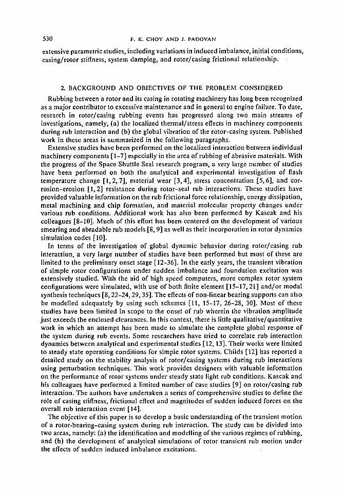
With the above assumptions, the response of the rotor before, during and after rub interaction can be separated into the following four regimes of operations: (i) no rotor/cas- ing contact; (ii) rub initiation; (iii) rub interaction; (iv) separation. Before rotor/casing contact the rotor motion vector g is smaller than the radial clearance gr. During this period, the rotor vector is dominated by the imbalance from all the initial operating conditions. For the rub model presented in Figure 1, the rotor vector can be described by a set of rotating polar co-ordinates i'r and 7~. By tracking the rotor geometric center,
�9 the equations of motion in both the i~ and i'~ directions (as illustrated in Figure 2) can
V//////////////// ~otor s~pporl
C o s i ~ ~ o r
Figure I. Schematic of rotor-casing model.

532 F. K. CHOY AND J. PADOVAN
/
Figure 2. Rotating co-ordinate s)stem.
~7
be written as, respectively,
m(~'- ~2a)+ C2{+ K,5 = me~{~2(cos 0 cos 4--1- sin 0 sin 4,)
- a(cos 0 sin 4 - s i n Ocos4)}
+ F~ cos 0 + Fy sin 0, ( 1 )
m(~8 + 2 ~ ) + C ~ 5 = me,,{~o2(sin O cos 4 ' - c o s 0 sin 4')
- a(sin 0 sin 4 +cos 0 cos 4)}
- & sin 4, + ~ cos 4'. (2)
A full derivation of equations (i) and (2) is given in the Appendix. During the rub initiation regime, the rotor establishes contact with the casing ( g ~ g,).
During this period, the rotor experiences a normal radial resisting force. This is due to the stiffness and damping effects of the casing. Its magnitude is proportional to the acceleration of the rotor and the angle of incident of the rotor center to the casing surface. The rotor is also subject to a resisting tangential force due to friction. At this stage, pure sliding occurs between the rotor and casing surfaces. This follows from the fact that, during initiation, little friction generated rotor retardation is built up. Specifically, during the initial phases of rub, the phase angle relationship between the rotor mass center and the motion of the geometric center begins to shift due to the effects of surface friction. This action is similar to damping. The equations of motion in the radial and angular directions at this stage can be written as, respectively,
m(~'- ~28) + C,6 + K,8 + K,(5 - 8,)
= me,{~2(cos 0 cos 4 + s i n 0 sin 4 ) - a(cos 0 sin 4 - s i n 0 cos 4)}
+ F~ cos 4' + Fy sin 4, (3)
m (,~,~ + 2r + C+,~,~ + ; g,(,~ - ,%)
= me,,{co2(sin 0 cos 4 - c o s 0 sin 4 ) - a(sin 0 sin 4 + c o s 0 cos 4)}
- F , sin 4 + Fy cos 4. (4)
These relations are also derived in the Appendix.

NON-LINEAR ROTOR-CASING R U a EVENTS 533
During the rubbing regime of operation the amplitude of motion of the rotor geometric center is larger than the radial clearance. Hence, rub interactions between the rotor and the casing surface occur. During this type of rub interaction, a combined motion of both sliding and rolling between the rotor and the casing surface occurs. This combined motion can be categorized into three different phases of rotor casing interaction: namely, (a) pure sliding; (b) a combination of sliding and rolling; (c) pure rolling. Pure sliding motion usually happens during the initial stages of the rub. The rotor geometric center is orbiting at a whirling speed & around the origin while the rotor itself is spinning at the rotational speed to. Before any kind of initial rub interaction, the rotor is assumed to be orbiting in a forward precession. This implies that both to and ~ are rotating in the same direction. Thus, the relative velocity V,/c between the two surfaces can be expressed as a function of the rotational speed to and whirling speed 6:
= ,q x + ( 5 )
Once contact is made between the rotor and the casing surfaces, the self-spinning effects of the rotor tends to induce a rolling action of the rotor on the casing surface. The frictional effects between the two surfaces produces a backward whirling force which tends to accelerate the whirling speed 6. Pure sliding effects will continue for 4~ > 0.
Once the frictional force induced during the pure sliding phase retards the motion of the rotor geometric center so as to change its direction, backward whirling, a combination of sliding and rolling will be induced. For this regime of operation, the friction still retards the whirling speed. As shown by equation (5), the relative velocity between the two surfaces does not vanish as long as 6 + to # 0. In particular sliding still occurs for 6 + to > 0. Note that pure rolling motion is induced when to = - 6 .
Separation of the rotor/casing surfaces will occur when the rotor motor amplitude is smaller than the radial clearance, namely, 8 > 8,. At this stage, the rotor geometric center tends to accelerate toward forward whirling type motion. In some cases, when the angle of incidence between the two surfaces is close to 90 degrees, the frictional force induced during rub interaction will retard the rotor mass center phase angle. This causes an angle ofseparation ofgreater than 90 degrees to occur. Overall such a process creates a whirling motion opposite to the rotational direction of the rotor a n d hence initiates a backward whirling orbit. Note that once the rotor casing separates, the overall dynamics of the system is then described by equations (1) and (2) defined earlier.
To account for the proper interface kinematics, the rub energy E due to Coulomb friction can be expressed as
E = , t z F , ( t ) 6 , ( t o + ~ ) dt, (6)
where tt and t2 are the starting and ending times of the rub interaction. A more complete discussion of the relationship between rub energy, the whirl speed ,~, the frictional coefficient/.t, and the normal force F, will be given in the next section of this paper.
4. DISCUSSION OF RESULTS
In order to demonstrate the various aspects of rotor/casing rub interactions, the Jeffcott rotor model shown in Figure i is modelled by a single mass with equivalent stiffness K, and damping C, characteristics as shown in Figure I. In order to avoid the inconsistent

534 F. K. C H O Y A N D J. P A D O V A N
effects introduced by different initial operating conditions, the rotor model is assumed to be operated at a steady state condition with an original imbalance eccentricity e~o. A sudden increase in imbalance will occur when the original rotor mass center passes through the positive x-axis while the rotor geometric center is making a phase angle fl with the positive x-axis.
With the appropriate initial conditions, equations (1)-(4) can be solved for both ~" and q~. Since the rotor motion will become non-linear when rubbing starts, a Newmark-/3 type implicit integration scheme [38] is used to integrate numerically the accelerations so as to evaluate the velocities and displacements of the rotor center at the next given step. Examples of the rotor motion and parametric studies of rub interaction will be discussed in this section. The system properties associated with the example considered herein are defined in Table 1.
TABLE 1
Rotor~casing data for transient study
Rotor weight Equivalent stillness Equivalent damping Rotor radius Casing radial clearance Original imbalance eccentricity External x-direction load External y-direction load Casing radial stiffness Casing radial damping Frictional coefficient Rotational speed of rotor Data value for integration
41b 10 0001b/in 0.5 lb s/in 1.5in 0.003 0.0001 in 0.0 Ib 0.01b 1 000 000 Ib in 0.0 Ib s/in 0.1 9072 rpm 0.25
As noted earlier, the overall rub interaction process consists of several major stages/phases of behavior. These include (a) rub initiation, (b) progressive steepening of angles of incidence and separation by friction forces, (c) onset of so-called backward whirl, and (d) long term attenuation due to system damping leading ultimately to steady state rub.
In the context of this scenario, the primary thrust of the numerical experiment is to determine the effects of the following system characteristics on the response behavior: (i) casing stiffness; (ii) imbalance load level; (iii) friction coefficient; (iv) system damping. Specific emphasis is given to monitoring (a) the rub forces, (b) the rotor casing angles of incidence and separation, and (c) the overall response motion, including initiation of backward whirl as well as analysis of rotor trajectory from transient to the steady state range of behavior.
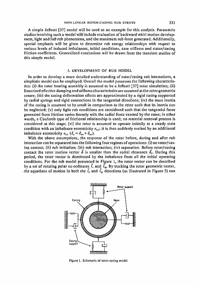
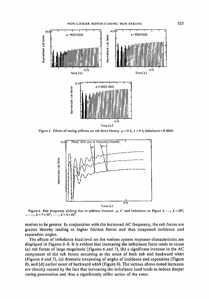
Figures 3-5 illustrate various aspects of the effects of casing stiffness on the rub forces and incidence/separation angles. These figures illustrate that, fora given level of imbalance load, increases in casing stiffness tend to cause (i) rub forces of larger magnitude, (ii) an increased frequency of the initial AC component of the rub forces occurring at the onset stage of rubbing, and (iii) steepening of angles of incidence and separation leading to earlier onset of backward whirl.
The increased frequency of the AC component follows directly from the fact that stiffening the casing causes the combined bearing-casing stiffness controlling the rotor
N O N - L I N E A R R O T O R - C A S I N G R U B E V E N T S 535
16-0
0 E 8 z
I I I I I I
K = 400 000
i lj IIIl!llllll,lJll1111!1111,11111!111111'1!I111 0.15
Time ( s )
i 16C , i ~ , i i
K �9 7 0 0 000
i 11Ill11 ;Ill I'l;llltL Lt LIIL/, tlIL,I i I/'/1 III1, , , = O~ 5, J
T i m e ( s )
160
16 0 K = 1 0 0 0 0 0 0
i ll,')li'i'!, Ll,,i,,llllltllllli l l a i
I
iiiiiiiiiiiii n i
015
T i m e ( s )
Figure 3~ Effects of casing stiffness on rub force history, bt = 0-1, e = 0 .5 , i m b a l a n c e = 0 0 0 0 9 .
Pr~s.e s h i l l d u e t o f r e q u e n t
~?,Ii~/cr ~J l ~ J "
V
, tncreose I
O 15 Time ( s )
Figure 4. Rub frequency shifting due to stiffness increase. /s, C and imbalance as Figure 3. ---, k = 106; , k =7xl0S; - - - , k =4x l0 s .
motion to be greater. In conjunction with the increased AC frequency, the rub forces are greater thereby leading to higher friction forces and thus steepened incidence a n d separation angles.
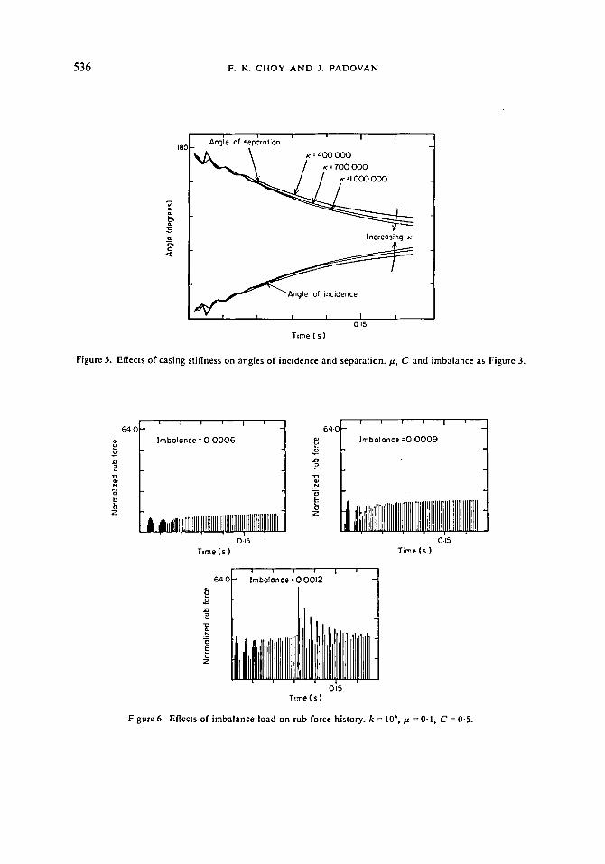
The effects o f imbalance load-level on the various system response characteristics are displayed in Figures 6-8. It is evident that increasing the imbalance force tends to cause (a) rub forces o f large magnitude (Figures 6 and 7), (b) a significant increase in the AC component o f the rub forces occurring at the onset o f both rub and backward whirl (Figures 6 and 7), (c) dramatic steepening o f angles o f incidence and separation (Figure 8), and (d) earlier onset o f backward whirl (Figure 8). The various above-noted increases are directly caused by the fact that increasing the imbalance load tends to induce deeper casing penetration and thus a significantly stiffer action of the rotor.
536 F. K. CIIOY A N D 3. PADOVAN
QJ
._w E
lSC i i i i j i Anqte of Seporotion
- ~ = = 400 000 K : 700 000
Increasing K
i ~ ~ i Angle of incidence
I t I t 015
Time ( s )
Figure 5. Effects o f casing stiffness on angles of incidence and separation. ,u, C and imbalance as Figure 3.
64 0
o E
Z
I I I i
Imbalance = O.O00G
I i
i j,, iEt [[[][ ]IIEt!!!IIIIII[IIIIlIIIIUIIIIII!II!IlIIII I O.t5
Time(s)
6qC
N
0 Z
Time (s) 015
64 0
o
3
Z
OI5 Time { s }
Figure& Effects of imbalance load on rub force history, k = 10 6,/~, =0"1, C =0.5 .

N O N - L I N E A R R O T O R - C A S I N G R U B E V E N T S 537
I
6 4 0
,I It^ - l l i l ~ f i g
, I i ,I !! ~,l ~ f~ i~. c , , . -~ . , . , , ,,. Li V V v "
l ; l ~ , i r i , l , , - , . i - . , . - - �9 �9 . | i ~ , t
li I Ill, u .--- _
I 0 t5
Tl~e (s)
Figure 7. Rub frequency shifting due to imbalance increase, k,/.L and C as Figure 6. Imbalance: . . . . , 0 . 0 0 0 6 ;
- - - - - 0 -0009 ; - - - , 0-0012.
The influence of friction effects is shown in Figures 9-11. Overall these figures illustrate that increases in the friction coefficient cause significant (a) steepening of the angles of incidence and separation leading to very early onset of backward whirl, and (b) increases in rub forces especially in the onset range of backward whirl. Such behavior is a direct outgrowth of the fact that since the friction force is tangential to the rotor and casing, it enables an interchange to occur between rotary and transverse energies. Because of the phasing involved, typically the direction of energy flow proceeds from the rotary to the transverse modes of motion. Hence increasing the friction tends to cause greater transverse motion leading to the actions noted earlier, namely, larger rub forces and hence an earlier onset of backward whirl.
, i i i 1 J A n g l e o f s e p a r a t i o n
~8r . ~ 00006
_ o,Ii ,,oo 1 \ J - oooo9 o f b o c k w o r d l----/~ ........
F *hirlJ~,,cf I ~ ,~00009
~.. , , - '~ " ~ _ - - - - - - - oooo6
0 15 Time I s 1
Figure 8. Effects of lmbalance load on angles of incidence and separation, k, N a n d C as Figure 6. Imbalance values shown on curves.

538 F. K. CilOY AND J. PADOVAN
1280]-" I 1 i i
/x : 0 . 0
�9 ~ l , - k ~ _ _ I I I I
Time ( s )
I
I 0~5
a 1280 i 1 1 | | I
~ = 0 0 5
I~ , l l , i l l I I I I~I I nl l l l l l l l l l I I lllllll JlHIIIIIIIIU i i i I I l
015 T i m e ( s )
r
E
128c l I I I | I
F , O . 1 5
m,,tiI~111111111~J~l~ ~IIIlilIt111111111111IIIIIIll I I I I I I
O.t$ T ime ( s )
Figure 9. Effects of friction on rub force history, k = 106, C = 0.5, imbalance = 0.0009.
128C
E
z
; I I l i " V l e - , v ~ - . . . . . .
Os5 "lime ( s )
Figure 10. Rub frequency shifting due to friction increase, k, C and imbalance as Figure 9. ----, pt =0.15; , / ~ = 0-05; - - - , / x = 0.00.
N O N - L I N E A R R O T O R - C A S I N G RUB E V E N T S 539
Angle of seporotion 18oo ~ . F=O-O
F:O-15
. . . . ~ . . . . "~ backwora
015 Time Is)
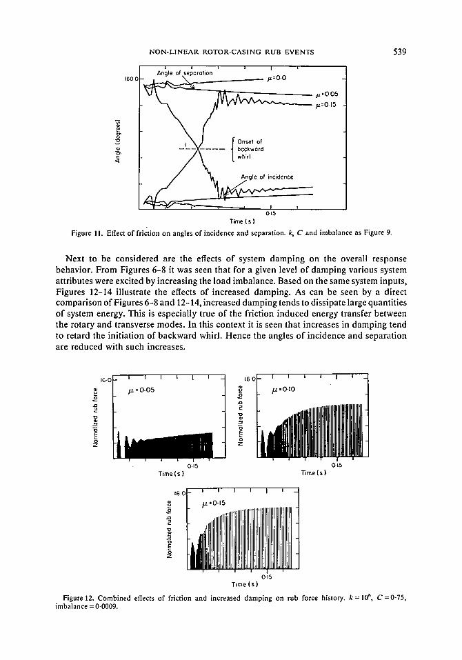
Figure 1 I. Effect of friction on angles of incidence and separation, k, C and imbalance as Figure 9.
Next to be considered are the effects of system damping on the overall response behavior. From Figures 6-8 it was seen that for a given level o f damping various system attributes were excited by increasing the load imbalance. Based on the same system inputs, Figures 12-14 illustrate the effects of increased damping. As can be seen by a direct comparison of Figures 6-8 and 12-14, increased damping tends to dissipate large quantities o f system energy. This is especially true o f the friction induced energy transfer between the rotary and transverse modes. In this context it is seen that increases in damping tend to retard the initiation of backward whirl. Hence the angles o f incidence and separation are reduced with such increases.
.N E E
z z
1 6 0
0.15 O.15 Time { s ) T i m e ( s )
16.0 l _ i I I I I i i
_ i ii,illiilll,l,llllil,ll,iillllllli,llll,lllll,llll ' i i i i I i 0.15
Time { s )
Figure 12. Combined effects of friction and increased damping on rub force history, k = 106, C = 0 . 7 5 , imbalance = 0.0009.

540 F. K. C H O Y A N D J. P A D O V A N
160
Z
f / j f . l
/ f / f - J
Hilt X , . , . . , -v ~1:11 v
" t ime (s )
I 015
Figure 13. Rub f requency sh i f t ing due to f r ic t ion a n d d a m p i n g increase , k, C and imba lance as Figure 12, . . . . , ja = 0 . 0 5 ; - - - - - , / 1 = 0.10; - - - , V- =0 .15 .
Finally, it is instructive to trace various of the foregoing effects by considering the overall rotor trajectory from transient to steady state behavior. For instance, consider the response histories defined in Figures 15-17. Figure 15 illustrates the orbital trajectories for the rotor casing system given in Table 1. As can be seen from the portion of the orbit depicted, no backward whirl is initiated. With Figure 15 as a reference base, Figures 16 and 17 illustrate the respective effects of increases in load imbalance and friction on the rotor trajectory. Specifically, from Figure 16, it is evident that increases in load imbalance can induce an earlier onset of backward whirl. As seen, the onset is marked by incidence and separation angles for which 0 > r For sucl, rotor trajectories typically the largest rub forces are noted during the onset of backward whirl. Figure 17 illustrates the rotor orbit associated with an increase in friction. Similarly to the previous case, an increase in friction coefficient can lead to an earlier onset of backward whirl.
= An91e ~ of ' = ! ' 5s LOCI / F:O'05
v
015 Time ( s )
Figure 14. C o m b i n e d effects of fr ict ion and d a m p i n g on angles o f inc idence and separa t ion , k, C and imba lance as F igure 12.

NON-LINEAR ROTOR-CASING RUB EVENTS 541
First ten revOlutiOnS Second ten revoluhons
Third fen r e v o l u h o n ~
Figure 15. Rotor orbit, Case I. k = 106, p = 0.1, C = 0.5, imbalance = 0.0009.
Compar ing Figures 16 and 17 shows that growth in both load imbalance and friction coefficient cause backward whirl. Note that growths which cause equivalent sized friction force componen t s lead to significantly different orbital trajectories. This is directly an ou tcome o f the ratioing between the normal and tangential components . In particular, for situations which involve a relatively higher ratio o f friction, the s teady state backward moving orbits tend to fill the clearance circle. This is clearly seen by compar ing Figures 16 and 17. Such behavior is an outgrowth o f the relative levels o f rotary to transverse energy transfer.
First ten tevobJttons Second ten r e v o l u t i o n s
i
Figure 16. Rotor orbit, Case II. As Figure 15 but imbalance =0.0012.

F. K. C i l O Y A N D J. P A D O V A N
F~rsI ten revolutions Second len revolutions
Third ten revolutions
542
Figure 17. Rotor orbit, Case III. As k = 106, p. =0-5, C = 0.5, imbalance = 0.0009.
In fu ture s tudies , the ettects o f cas ing iner t ia as well as tu rb ine b l a d e / i m p e l l e r stiffness will be cons ide red in the analys is o f ro to r -b lade -cas ing rubs. Add i t i ona l l y , the b l a d e / i m p e l l e r p i tch d i s tance a n d aspect ra t io will be a c c o m m o d a t e d in the model l ing .
REFERENCES
!. R. C. BILL and L. P. LUDWIG 1980 Wear 59, 191-211. Wear ofseal materials used in aircraft propulsion system.
2. W. D. MARSCItER 1982 Presented at the 1982 ASLE Annnal Afeeting. Test simulation of turbomachinery rotor-stator interactions.
3. J. WOLAK 1983 Presented at Gas Path Seal Rub Energetic Wor'kshop, NASA Lewis Research Center, December 1983. Blade tip geometry--a factor in abrading sintered seal.
4. P.C. NOVAK 1983 Third Interim Technical Report prepared for Wright-Patterson AFB, Department of Air Force, under contract No. T-33616-83-C-5026. Development of improved turbine seal and turbine blade tip system.
5. 1t. C. PEDERSON 1985 Report prepared for NASA Lewis Research Center under Contract No. NAS3-22813. Abrasive tip treatment for use on compressor blades.
6. J. PADOVAN 1987 American Institute of Aeronautics and Astronautics Journal (in press). Thermo-elastic-plastic creep stresses in ceramic coatings.
7. W. D. MARSCIIER 1981 ASLE Paper No. 81-AM-ID3 Presented at the 36th Annual Meeting, Pittsburg, Pennsylvania. A critical evaluation of the flash-temperature concept.
8. A. F. KASCAK 1980 AVRARCOM Tr-80-C-14. The response of turbine engine rotors to interference rubs.
9. A. F. KASCAK and J. J. TOMKO 1983 NASA TP 2220, A VSCOM Tr-83-C-8. Effects ofdifferent rub models on simulated rotor dynamics.
10. A. F. KASCAK 1979 NASA TP-1597, AVRADCOM Tr-79-42. Direct integration of transient rotor dynamics.
11. H. D. NELSON, W. L. MEACHAM, D. P. FLEMING and A. F. KASCAK 1983 American Society of Mechanical Engineers Journal of Engineering for Power 105, 606-614. Nonlinear analysis of rotor-bearing systems using component mode synthesis.
12. D. W. CIIILDS 1979 American Society of Mechanical Engineers Journal of Mechanical Design 10, 640-644. Rub induced parametric excitation in rotors.

NON-LINEAR ROTOR-CASING RUB EVENTS 543
13. D. E. BENTLY 1974 ASME Paper 74-DET-16, Petroleum Mechanical Engineering Conference, Dallas, Texas, 15-18 September. Forced subrotative speed dynamic action of rotating machiners.
14. K. C. CIIOY and J. PADOVAN 1985 Proceedings of the 40th Mechanical Failures Prevention Group Symposium, Gaithersburg, Maryland, April 1985. Investigation of rub effects on rotor- bearing-casing system response.
15. M. L. ADAMS, J. PADOVAN and D. G. FER-IIS 1982 Journal of Engineering for Power 104, 586-593. Engine dynamic analysis with general nonlinear finite element codes--Part 1: Overall approach and development of bearing damper element.
16. J. PADOVAN, M. ADAMS, D. FERTIS, I. ZEID and P. LAM 1982 Gas Turbine Conference of ASME, Paper No. 82-GT-292. Engine dynamic analysis with general nonlinear finite element codes--Part II: Bearing element implementation, overall numerical characteristics and bench- marking.
17. J. PADOVAN, M. ADAMS, D. FERTIS, 1. ZEID and P. LAM 1984 Journal of Computers and Structures 18, 629-639. Nonlinear transient finite element analysis of rotor.bearing-stator systems.
18. M. L. ADAMS and J. PADOVAN 1981 Journal of Sound and Vibration 76, 129-142. Insights into linearized rotor dynamics.
19. R. G. KIRK and D. H. HIBNER 1976 ASME Journal of Engineering for Industry 98 (Series B), 437-504. A note on blade loss dynamics of rotor-bearing systems.
20. M. SAKATA, T. AIBA and H. OtlNAKE 1982 ASME Paper No. 82-GT-231, Gas Turbine Conference. Transient vibration of high speed lightweight rotor due to sudden imbalance.
21. K.E. ROUCII andJ .S . KAO 1980 American Society of Mechanical Engineers Journal of Alecbanical Design 102, 360-368. Dynamic reduction in rotor dynamics by the finite element method.
22. E.J. GUNTER, K. C. CHOY and P. E. ALLAIRE 1978 Journal of Franklin Institute 305, 221-243. Modal analysis of turborotor using planar modes theory.
23. K.C. CtlOu E. J. GUNTER and P. E. ALLAIRE 1978 Presented at the ASME Design Engineering Conference and Shows, Illinois, April 1978. Fast Fourier transform Analysis of rotor-bearing
�9 systems. 24. M. L. ADAMS 1980 Journal of Sound and Vibration 71,129-144. Non-linear dynamics of flexible
multi-bearing rotors. 25. J. M. VANCE 1975 Journal of Aircraft, 12, 295-303. High speed rotor dynamics: an assessment
of current technology for small turboshaft engines. 26. D. F. LI, K. C. CHOY and P. E. ALLAIRE 1980 American Society of Mechanical Engineers
Journal of Lubrication Technolog), 102, 291-299. Stability and transient characteristics of four multilobe journal bearing configurations.
27. P. E. ALLAIRE, D. F. LI and K. C. Clio'," 1980 American Society of Mechanical Engineers Journal of Lubrication Technology 102,300-307. Transient unbalance response of four multilobe journal bearings.
28. J. M. VANCE 1978 American Society of Mechanical Engineers Journal of Mechanical Design 100, 139-146. Squeeze film damper characteristics for gas turbine engines.
29. D. W. CtlILD 1978 American Society of Mechanical Engineers Journal of Engineering for Power 100, 48-57. The space shuttle main engine high pressure fuel turbopump rotordynamic instability problem.
30. D. W. CHILD 1983 Transactions of the American Society of Mechanical Engineers Journal of Lubrication Technology 105, 429-436. Dynamic analysis of turbulent annular seals based on Hits' lubrication equation.
31. A. B. PALAZZOLO, K. C. CIIOu and E. J. GUNTER 1977 Uni~'ersity of Virginia Research Report to NASA Alarshall Space Flight Center (NASA Contract NANS8-31951). Dynamic analysis of space shuttle main engine oxygen turbopump.
32. G. E. ENRICil 1969 ASME Journal of Engineering for lndustr)' 91, 1025-1028. The dynamic stability of rotor-stator radial rubs in rotating machinery.
33. tt. F. BLACK 1966 Institute of Mechanical Engineers Conference on Vibration of Hydraulic Pumps and Turbines, Manchester. Synchronous whirling of a shaft within a radially flexible annulus having small radial clearance.
34. H. F. BLACK 1968 Journal of Mechanical Engineering Science 10, 1-12. Interaction of a whirling rotor with a vibrating stator across a clearance annulus.
35. E. J. GUNTER 1965 NASA SP-113. Dynamic stability of rotor-bearing system. 36. K. C. CHOY, E. J. GUNTER and P. E. ALLAIRE Computer program on "'Rotor Transient
Analysis by Modal Method". Distributed by Cosmic Library of NASA (Program No. LEW- 13230. Abstract published in NASA Technical Brief, Volume 5, No. 2, of Summer 1980).

544 F. K. C I I O Y A N D J. P A D O V A N
37. tt. H. JEFFCO"IT 1919 Philosophical Magazine Series 6, 37, 304. The lateral vibration of loaded shifts in the neighborhood of a whirling speed--the effects of want of balance.
38. R. E. NICKELL 1971 International Journal of Solids and Stntctures 7, 301-309. On stability of approximation operators in problems of structural dynamics.
APPENDIX
For the Jeffcott rotor shown in Figure 1, the displacement vector of the geometric center of the disc can be represented by g as shown in Figure 2. The origin of the Cartesian co-ordinate system x, y, z is coincident with the original undisplaced geometric rotor center at O. The rotor motion can also be represented by a rotating polar co-ordinate system with unit vectors (i , , i,~) tracking the rotor center motion as shown in Figure 2. In terms of the rotating polar co-ordinates, the displacement, velocity and acceleration of the rotor center are given by the expressions
g = ~5i',, Vc = ~ i", + q~Si'~, (AI, A2)
dc = gi-, + ~8i~ + 26~i'6 - q~ ~5 i',. (A3)
For a suddenly excited eccentric rotor system with an original mass center of distance e~o from the geometric center of the rotor, the relative location is defined by a phase angle /3 as shown in Figure 2. In particular, the relative motion of the mass and the geometric centers of the rotor can be expressed as
P,,/c = eu[cos (o~t +/3) i"+ sin (wt +/3)f ' ] , (A4)
where i" and "-" . / , are a set of rectangular co-ordinates attached to the geometric center of the rotor. The vectorial location of the mass center can also be expressed in terms of rotating polar co-ordinates. With i',. and 70. having an origin at the rotor geometric center, such a vectorial representation is given by
~. = euz,.. (A5)
Based on equation (A5), the relative velocity IP,,,/~ and acceleration 6,,/~ can be expressed as
I/,,/~ = e, wi",,, a,,/~ = e~aio.- e~w 2 i",. (A6, A7)
where a = d w / d t . In terms of equation (A7), the absolute acceleration of the mass center is given by
6,. = a,./r + 6r (A8)
or, in full, one has that
am = i'o.- ,o r i',.) + ( g - i', + (84; + f,,. (A9)
Through transformation of co-ordinates, the motion of the mass center can be expressed in terms of i', and re, to yield
where
{ i',.} = [cos 0 cos ~b +sin 0 sin 4)
i'o' L-s in 0 cos 4) + cos 0 sin 4)
-cos 0 sin 4) +sin 0 cos ~ ] { i,} sin 0 sin 4)+cos 0 cos i'~ '
O=/3+oJt, 4)= 6 d t .
(Mo)
(AI I ,AI2)

NON-LINEAR ROTOR-CASING RUB EVENTS 545
Thus the acceleration vector of the center of mass of the rotor can be expressed as
5,. = {~'- ~28 + e.a(cos 0 sin 4' - s i n 0 cos ~b)
- e.w2(cos 0 cos ~b+sin 0 sin ~b)} i',
+ { 8 ~ + 2 ~ + e.a(sin 0 sin ~b +cos 0 cos ~b)
- euw2(sin 0 cos ~b-cos 0 sin ~b)} t" 6. (AI3)
During rotor motion when the displacement 8 is smaller than the radial clearance ~5,(8> 8,). no rub interaction will occur. Hence, for such situations, the equation of motion can be written in the general form
rod,,, + C~V~+ Kefic = Pcxt, (A14)
where Pext are the external loads such that
Fex, = Fxf+ ~..L (A15)
Separated into i', and i'r components, equation (A14) yields, respectively,
r e ( g - ~28) + Ce~ + K~8 = m e . { J ( c o s 0 cos r + sin 0 sin 4')
- a(cos 0 sin 4' - s i n ~b cos ,b)}
+ Fx cos ~b + Fy sin 4'. (A16)
m(q~B +2~,8) + C,~b~ = me,{a,2(sin 0 cos ~b - c o s 0 sin )
- a ( s i n 0 sin qS+cos 0 cos ~b)}- F~ sin 4,+Fy cos ~b. (A17)
When 8 is greater than or equal to 8,, rub type rotor/casing interaction commences. For the current purposes, the casing is assumed to possess the following attributes: (i) it is stiffer tangentially than radially; (ii) it has a greater mass than the rotor; (iii) it possesses radial damping characteristics. Given such properties, the casing can be modelled as a flexible foundation with both radial stiffness and damping characteristics, but infinitely rigid tangentially. In terms of such attributes, the equations defining casing-rotor rub interaction, in the radial and angular directions, respectively, are
m(~ ' - ~b~8) + Kr + K, (8 - 8,) + C,~
= me,{a,2(cos 0 cos ~b +sin 0 sin 0 ) - a(cos 0 sin q~-sin 0 cos 4')}
+ F.~ cos q~ + Fy sin ~b, (AI8)
,,,(68 + 26 ) + c 6s + t ,K , ( - a,)
= me,{w2(sin 0 cos ~b-cos 0 sin ~b)- a(sin 0 sin i f+cos 0 cos 6)}
- Fx sin 4' + Fy cos ~b. (A19)