rra study of - welcome to...
TRANSCRIPT

RRA Study of BS VI MS Block Project BPCL Kochi Refinery
Doc No: A870-17-43-RRA-0001 Rev. No.: 0
Page 2 of 38
Template No. 5-0000-0001-T2 Rev. 1 Copyrights EIL ¬ All rights reserved
PREFACE
BPCL intends to maximize and upgrade MS processing capabilities to meet BSVI fuel
specifications by 1st April 2020. This document forms a part of EIA report for BSVI quality fuels
production.
Rapid Risk Analysis study identifies the hazards associated with the facility, analyses the
consequences, draws suitable conclusions and provides necessary recommendations to mitigate
the hazard/ risk.
This Rapid Risk Analysis study is based on the information made available at the time of this
study and EIL’s own data source for similar plants. EIL has exercised all reasonable skill, care
and diligence in carrying out the study. However, this report is not deemed to be any undertaking,
warrantee or certificate.

RRA Study of BS VI MS Block Project BPCL Kochi Refinery
Doc No: A870-17-43-RRA-0001 Rev. No.: 0
Page 3 of 38
Template No. 5-0000-0001-T2 Rev. 1 Copyrights EIL ¬ All rights reserved
TABLE OF CONTENTS
1 EXECUTIVE SUMMARY .......................................................................................................... 6
1.1 INTRODUCTION ............................................................................................................... 6
1.2 APPROACH METHODOLOGY ......................................................................................... 6
1.3 MAJOR OBSERVATIONS & RECOMMENDATIONS ....................................................... 7
2 INTRODCUTION ...................................................................................................................... 9
2.1 STUDY AIMS AND OBJECTIVE ....................................................................................... 9
2.2 SCOPE OF WORK ............................................................................................................ 9
3 SITE CONDITION ................................................................................................................... 10
3.1 GENERAL ....................................................................................................................... 10
3.2 SITE, LOCATION AND VICINITY ................................................................................... 10
3.3 METEOROLOGICAL CONDITIONS ............................................................................... 10
4 HAZARDS ASSOCIATED WITH THE FACILITIES ................................................................ 14
4.1 GENERAL ....................................................................................................................... 14
4.2 HAZARDS ASSOCIATED WITH FLAMMABLE MATERIALS ......................................... 14
4.2.1 LIQUIFIED PETROLEUM GAS ................................................................................ 14
4.2.2 HYDROGEN ............................................................................................................. 14
4.2.3 NAPHTHA AND OTHER HEAVIER HYDROCARBONS .......................................... 15
4.3 HAZARDS ASSOCIATED WITH TOXIC MATERIALS .................................................... 16
4.3.1 HYDROGEN SULPHIDE .......................................................................................... 16
4.3.2 BENZENE ................................................................................................................ 16
4.3.3 TOLUENE ................................................................................................................ 17
5 HAZARD IDENTIFICATION ................................................................................................... 19
5.1 GENERAL ....................................................................................................................... 19
5.2 MODES OF FAILURE ..................................................................................................... 19
5.3 SELECTED FAILURE CASES ........................................................................................ 20
6 CONSEQUENCE ANALYSIS ................................................................................................. 22
6.1 GENERAL ....................................................................................................................... 22
6.2 CONSEQUENCE ANALYSIS MODELLING .................................................................... 22
6.2.1 DISCHARGE RATE ................................................................................................. 22

RRA Study of BS VI MS Block Project BPCL Kochi Refinery
Doc No: A870-17-43-RRA-0001 Rev. No.: 0
Page 4 of 38
Template No. 5-0000-0001-T2 Rev. 1 Copyrights EIL ¬ All rights reserved
6.2.2 DISPERSION ........................................................................................................... 22
6.2.3 FLASH FIRE ............................................................................................................. 22
6.2.4 JET FIRE .................................................................................................................. 23
6.2.5 POOL FIRE .............................................................................................................. 23
6.2.6 VAPOR CLOUD EXPLOSION ................................................................................. 23
6.2.7 TOXIC RELEASE ..................................................................................................... 23
6.3 SIZE AND DURATION OF RELEASE ............................................................................. 23
6.4 DAMAGE CRITERIA ....................................................................................................... 24
6.4.1 LFL OR FLASH FIRE ............................................................................................... 24
6.4.2 THERMAL HAZARD DUE TO POOL FIRE, JET FIRE AND FIRE BALL ................. 24
6.4.3 VAPOR CLOUD EXPLOSION ................................................................................. 25
6.4.4 TOXIC HAZARD ....................................................................................................... 25
6.5 CONSEQUENCE ANALYSIS FOR MS BLOCK .............................................................. 26
6.5.1 NHT .......................................................................................................................... 26
6.5.2 CCR .......................................................................................................................... 27
6.5.3 ISOMERIZATION UNIT ............................................................................................ 28
6.5.4 OFFSITES ................................................................................................................ 30
7 OBSERVATIONS & RECOMMENDATIONS .......................................................................... 31
8 GLOSSARY ............................................................................................................................ 36
9 REFERENCES ....................................................................................................................... 38
ANNEXURE-I: CONSEQUENCE ANALYSIS HAZARD DISTANCES
ANNEXURE-II: FIGURES FOR CONSEQUENCE ANALYSIS OF MS BLOCK
ANNEXURE-II: INDIVIDUAL RISK CONTOUR
RRA Study of BS VI MS Block Project BPCL Kochi Refinery
Doc No: A870-17-43-RRA-0001 Rev. No.: 0
Page 5 of 38
Template No. 5-0000-0001-T2 Rev. 1 Copyrights EIL ¬ All rights reserved
LIST OF TABLES
Table 1: New Proposed Process Facilities under BSVI Project ......................................................................... 9
Table 2: Atmospheric Parameter ..................................................................................................................................... 11
Table 3: Average Mean Wind Speed (m/s) ................................................................................................................. 11
Table 4: % Number of Days Wind From ....................................................................................................................... 11
Table 5: Pasquill Stability Classes................................................................................................................................... 12
Table 6: Weather Conditions .............................................................................................................................................. 13
Table 7: Hazardous Properties of LPG ......................................................................................................................... 14
Table 8: Hazardous Properties of Hydrogen .............................................................................................................. 15
Table 9: Hazardous Properties of Naphtha 15
Table 10: Toxic Effects of Hydrogen Sulphide .......................................................................................................... 16
Table 11: Hazardous Properties of Benzene ............................................................................................................. 17
Table 12: Toxic effects of Benzene ................................................................................................................................. 17
Table 13: Hazardous Properties of Toluene ............................................................................................................... 18
Table 14: Toxic effects of Toluene .................................................................................................................................. 18
Table 15: Size of Release .................................................................................................................................................... 23
Table 16: Damage Due to Incident Thermal Radiation Intensity ..................................................................... 24
Table 17: Damage Effects of Blast Overpressure ................................................................................................... 25
LIST OF FIGURES
Figure 1: BPCLKochi Refinery Site ................................................................................................ 10

RRA Study of BS VI MS Block Project BPCL Kochi Refinery
Doc No: A870-17-43-RRA-0001 Rev. No.: 0
Page 6 of 38
Template No. 5-0000-0001-T2 Rev. 1 Copyrights EIL ¬ All rights reserved
1 EXECUTIVE SUMMARY
1.1 INTRODUCTION
The Kochi Refinery of Bharat Petroleum Corporation Limited (BPCL-KR) located at Ambalamugal,
in Ernakulum District (Kerala), India, was established in 1966 and has been expanded to current
capacity of 9.5 Million Metric tons per Annum (MMTPA) through successive revamps/ new
facilities. It currently has two trains of primary distillation units (CDUI and II), secondary
processing facilities viz VGO-HDS, FCCU, DHDS, petrochemicals like benzene toluene
production facilities and other associated utilities and offsites.
As per Auto Fuel Policy 2025, The Ministry of Petroleum and Natural gas laid down a roadmap for
complete transition to BS IV automotive fuel by the end of 2017 and the transition to BS VI
automotive fuel is slated to take place and completed by 1 April 2020 in the entire country.
Though, in post IREP scenario, BPCL Kochi Refinery will be able to produce BS IV quality MS
and Diesel along with partial production of BS VI products, it will require additional facilities to
achieve BS-VI quality specifications for MS. In view of the above, BPCL intends to maximize and
upgrade MS processing capabilities to meet BSVI fuel specifications by year 1st April 2020.
BPCL intends to maximize and upgrade MS to meet BSVI fuel specifications by 1st April 2020.
This document forms a part of EIA report for BSVI quality fuels production.
1.2 APPROACH METHODOLOGY
RRA study evaluates the consequences of potential failure scenarios, assess extent of damages,
based on damage criteria’s and suggest suitable measures for mitigating the Hazard.
RRA involves identification of various potential hazards & credible or reasonably believable failure
scenarios for various units based on their frequency of occurrence & resulting consequence.
Basically two types of scenarios are identified spanning across various process facilities; Cases
with high chance of occurrence but having low consequence, e.g., Instrument Tapping Failure and
cases with low chance of occurrence but having high consequence, e.g.,Catastrophic Rupture of
Pressure Vessels / Large Hole on the outlet of Pressure Vessels. Effect zones for various
outcomes of failure scenarios (Flash Fire, Jet Fire, Pool Fire, Blast overpressure, toxic release,
etc.) are studied and identified in terms of distances on plot plan. Based on effect zones,
measures for mitigation of the hazard/risk are suggested.

RRA Study of BS VI MS Block Project BPCL Kochi Refinery
Doc No: A870-17-43-RRA-0001 Rev. No.: 0
Page 7 of 38
Template No. 5-0000-0001-T2 Rev. 1 Copyrights EIL ¬ All rights reserved
1.3 MAJOR OBSERVATIONS & RECOMMENDATIONS
The major credible failure scenarios are modeled in terms of hydrocarbon release rate,
dispersion, flammability & toxic characteristics and detailed consequence analysis of the
outcomes is presented in the Rapid Risk Analysis (RRA) report. The summary of major
observations & recommendations of RRA study for new MS block is recorded below. Refer
Section - 7 for Observations and recommendations.
High frequency credible failure scenarios for ISOM Unit are modeled. In the event of instrument
tapping failure of charge pumps, 20mm leak in the isomerate product-Stabilizer outlet, it was
observed that LFL is largely restricted within the complex boundary for the most probable wind
conditions. The 5 & 3 psi blast waves may affect adjacent existing NHT/CCR units and upcoming
facilities nearby but may not be realized beyond the complex boundaries. However to mitigate the
onsite consequences, it is recommended:
Provide sufficient number of hydrocarbon detectors within the ISOM unit for early leak
detection and develop procedures for stopping of rotating equipments and quicker
inventory isolation.
The consequences of low frequency (in the order of 1 x10⁻⁶ /M-year to 1 x10⁻⁷ /M-year) credible
cases of ISOM unit may be included for updation of the existing Disaster Management Plan
(DMP) & Emergency Response Plan (ERP).
In case of the Instrument tapping failure at Separator Pumps and Reformate product pump
instrument tapping failure of CCR unit. The IDLH toxic concentration of 500ppm may be
experienced at chemical ware house, SRR-2, gate house, fire station, QC lab, SRR-3, and
Substation (S/S-1) on the northern and eastern side of the unit with a possibility of crossing the
complex boundary on the northern and southern side and may further be realized beyond the
main road on the eastern side, based on orientation of the leak and the weather conditions
prevailing at the time of release. However, an individual risk assessment of credible leakage
scenarios has shown that IR risk contour of 1 x 10⁻⁶/Avg- year, which is considered to
demonstrate broadly acceptable region for public, is within the BPCL complex premises.
Based on preceding observations the following is recommended:
Provide adequate number of hydrocarbon detectors at suitable locations within the unit and at
the periphery of the unit for early leak detection. Also mitigating procedures such emergency
shutdown of rotating equipments and quick isolation of inventories shall be developed as a
part of the Emergency response plan & Disaster Management Plan to address the concerns
of high frequency failure scenarios.
The CCR separator and De-butanizer and reformate may preferably be located to the
western side of the piperack to maintain as much distance as possible from compound wall.

RRA Study of BS VI MS Block Project BPCL Kochi Refinery
Doc No: A870-17-43-RRA-0001 Rev. No.: 0
Page 8 of 38
Template No. 5-0000-0001-T2 Rev. 1 Copyrights EIL ¬ All rights reserved
As the Quality Control lab may be affected by the toxic concentration of Toluene, suitable no.
of breathing apparatus may be provided to be used in case of emergency based on detection
or emergency guidelines.
In the offsites, existing CCR feed Tank YT-903 may be affected by 32 & 8 KW/m2 jet fire radiation
intensities due to NHT feed pump instrument tapping failure. Also the tank YT-903 may be
subjected to direct flame impingement and may lead to escalation. It is recommended to:
Locate the new pumps atleast 40m away from the Tankage so as avoid direct flame
impingement. Review the suitability of active fire protection system of Tank YT-903 for
protection from 32KW/m2 radiation intensity.
The active fire protection system provided for storage tanks (YT-903/905) are to be
regularly checked for prompt action.
As the control room may not be exposed to LFL, but may be partially subjected to blast
overpressures, based on the prevailing site conditions and presence of ignition sources,
ensure suitable mitigation by early leak detection and automated inventory isolation.
Outcomes of the low frequency (in the order of 1 x10⁻⁶ /M-year to 1 x10⁻⁷/M-year) credible failure
scenarios for various units are recommended to be included for updating of the existing Disaster
Management Plan (DMP) & Emergency Response Plan (ERP).

RRA Study of BS VI MS Block Project BPCL Kochi Refinery
Doc No: A870-17-43-RRA-0001 Rev. No.: 0
Page 9 of 38
Template No. 5-0000-0001-T2 Rev. 1 Copyrights EIL ¬ All rights reserved
2 INTRODCUTION
2.1 STUDY AIMS AND OBJECTIVE
The objectives of the Rapid Risk Analysis study are to identify and quantify all potential failure
modes that may lead to hazardous consequences. Typical hazardous consequences include fire,
explosion and toxic releases. The Rapid Risk analysis identifies potential hazardous
consequences having impacts on population and property in the vicinity of the facilities, and
provides information necessary in developing strategies to prevent accidents and formulate the
Disaster Management Plan.
The Rapid Risk Analysis includes the following steps:
a) Identification of failure cases within the process facilities
b) Evaluate process hazards emanating from the identified potential accident scenarios.
c) Analyze the damage effects to surroundings due to such incidents.
d) Suggest mitigating measures to reduce the hazard / risk.
The Risk analysis study has been carried out using the risk assessment software program
‘PHAST ver. 6.7 developed by DNV Technica.
2.2 SCOPE OF WORK
The study addresses the hazards that can be realized due to operations associated with the
proposed facilities under BS VI Project. It covers the following facilities of proposed BS VI project
facilities:
Table 1: New Proposed Process Facilities under BSVI Project
S. No. Description Remarks
1. NHT 1. 5MMTPA
2. CCR 0.8 MMTPA
3. ISOM 0.71 MMTPA
4. Tankages
1 NHT feed tank
1 Isom feed
1 CCR feed
5. Feed Pumps
3 No’s NHT feed
2 No’ s Isom Feed
2 No’s CCR feed

RRA Study of BS VI MS Block Project BPCL Kochi Refinery
Doc No: A870-17-43-RRA-0001 Rev. No.: 0
Page 10 of 38
Template No. 5-0000-0001-T2 Rev. 1 Copyrights EIL ¬ All rights reserved
3 SITE CONDITION
3.1 GENERAL
This chapter describes the location of BPCL Kochi Refinery complex and meteorological data,
which have been used for the Rapid Risk Analysis study.
3.2 SITE, LOCATION AND VICINITY
The BPCL Kochi Refinery is located in Ambalamugal, in Ernakulum District (Kerala). The site is
located approximately at Latitude of 9◦58’16″N and longitude of 76◦22’43″E.
Figure 1: BPCL Kochi Refinery Site
3.3 METEOROLOGICAL CONDITIONS
The consequences of released toxic or flammable material are largely dependent on the
prevailing weather conditions. For the assessment of major scenarios involving release of toxic or
flammable materials, the most important meteorological parameters are those that affect the
atmospheric dispersion of the escaping material. The crucial variables are wind direction, wind
speed, atmospheric stability and temperature. Rainfall does not have any direct bearing on the
results of the risk analysis; however, it can have beneficial effects by absorption / washout of
released materials. Actual behavior of any release would largely depend on prevailing weather
condition at the time of release.
For the Risk Analysis study, Meteorological data of Kochi has been taken from the QRA report of
facilities at BPCL Kochi prepared by M/s EIL, using the Climatological Tables of Observatories in
India (1961-1990) published by Indian Meteorological Department, Pune.

RRA Study of BS VI MS Block Project BPCL Kochi Refinery
Doc No: A870-17-43-RRA-0001 Rev. No.: 0
Page 11 of 38
Template No. 5-0000-0001-T2 Rev. 1 Copyrights EIL ¬ All rights reserved
Atmospheric Parameters
The Climatological data which have been used for the Risk Analysis study is summarized below:
Table 2: Atmospheric Parameter
Sl. No. Parameter Average Value Considered For Study
1. Ambient Temperature (OC) 27
2. Atmospheric Pressure (mm Hg) 760
3. Relative Humidity (%) 82
4. Solar Radiation flux (kW/m2) 0.7
Wind Speed and Wind Direction
The meteorological data considered for the study has been taken from the IMD Table (Kochi
weather station).
The averages mean speed and the wind from various directions in percentage number of days is
as in table below. It is observed from the IMD data that calm weather is experienced for 12% of
the time in the night and 1.6% in the day time. Predominant wind speed for Kochi is in the range
of 1 m/s to a maximum of 2.5 m/s. The study of oktas (all clouds) shows that the months of April
to November are very cloudy and December to March is moderately cloudy.
Table 3: Average Mean Wind Speed (m/s)
Jan Feb Mar April May June July Aug Sep Oct Nov Dec
1.58 1.7 1.9 2 1.92 1.58 1.47 1.61 1.6 1.5 1.41 1.36
Table 4: % Number of Days Wind From
N NE E SE S SW W NW Calm
Day 3.19 1.1 1.1 1.1 2.13 14.9 45.7 31.89 3.19
Night 9 29 36 9 1.8 1.8 5.4 7.2 9
Weather Category
One of the most important characteristics of atmosphere is its stability. Stability of atmosphere is
its tendency to resist vertical motion or to suppress existing turbulence. This tendency directly
influences the ability of atmosphere to disperse pollutants emitted into it from the facilities. In most
dispersion scenarios, the relevant atmospheric layer is that nearest to the ground, varying in
thickness from a few meters to a few thousand meters. Turbulence induced by buoyancy forces in
the atmosphere is closely related to the vertical temperature gradient.
Temperature normally decreases with increasing height in the atmosphere. The rate at which the
temperature of air decreases with height is called Environmental Lapse Rate (ELR). It will vary

RRA Study of BS VI MS Block Project BPCL Kochi Refinery
Doc No: A870-17-43-RRA-0001 Rev. No.: 0
Page 12 of 38
Template No. 5-0000-0001-T2 Rev. 1 Copyrights EIL ¬ All rights reserved
from time to time and from place to place. The atmosphere is said to be stable, neutral or unstable
according to ELR is less than, equal to or greater than Dry Adiabatic Lapse Rate (DALR), which is
a constant value of 0.98°C/100 meters.
Pasquill stability parameter, based on Pasquill – Gifford categorization, is such a meteorological
parameter, which decreases the stability of atmosphere, i.e., the degree of convective turbulence.
Pasquill has defined six stability classes ranging from `A' (extremely unstable) to `F' (stable). Wind
speeds, intensity of solar radiation (daytime insulation) and nighttime sky cover have been
identified as prime factors defining these stability categories. Below Table indicates the various
Pasquill stability classes.
Table 5: Pasquill Stability Classes
Surface Wind Speed
(meter/s)
Day time solar radiation Night time cloud cover
Strong Medium Slight Thin < 3/8 Medium 3/8 Overcast >4/5
< 2 A A – B B - - D
2 – 3 A – B B C E F D
3 – 5 B B – C C D E D
5 – 6 C C – D D D D D
> 6 C D D D D D
Source: PHAST Manual A = Very unstable, B = Unstable, C = moderately unstable, D = Neutral, E = moderately stable, F = stable
Source : CCPS Book on A Guide to Quantitative Risk Analysis
Legend: A = Very unstable, B = Unstable, C = Moderately unstable, D = Neutral, E = Moderately
stable, F = stable
When the atmosphere is unstable and wind speeds are moderate or high or gusty, rapid
dispersion of pollutants will occur. Under these conditions, pollutant concentrations in air will be
moderate or low and the material will be dispersed rapidly. When the atmosphere is stable and
wind speed is low, dispersion of material will be limited and pollutant concentration in air will be

RRA Study of BS VI MS Block Project BPCL Kochi Refinery
Doc No: A870-17-43-RRA-0001 Rev. No.: 0
Page 13 of 38
Template No. 5-0000-0001-T2 Rev. 1 Copyrights EIL ¬ All rights reserved
high. In general worst dispersion conditions (i.e. contributing to greater hazard distances) occur
during low wind speed and very stable weather conditions, such as that at 1F weather condition
(i.e. 1 m/s wind speed and Pasquill Stability F).
Stability category for the present study is identified based on the cloud amount and wind speed.
For risk analysis the representative average annual weather conditions are assessed based on
the following:
Literature suggests that Category ‘D’ is most probable at coastal sites in moderate climates, and
may occur for up to 80% of the time. Hence, Pasquill stability category best represented for the
present facilities would be category ‘D’ (neutral).Pasquill Stability F has been considered for
accounting the night time weather.
Table 6: Weather Conditions
Wind Speed Pasquill Stability
1 F
1.5 C/D
2.5 D
Note: For RRA Study Plot Plan (Doc. No.: A870-000-17-44-0001 Rev A) has been used.
The consequence results are reported in tabular form for all the weather conditions and are
represented graphically for worst weather condition.

RRA Study of BS VI MS Block Project BPCL Kochi Refinery
Doc No: A870-17-43-RRA-0001 Rev. No.: 0
Page 14 of 38
Template No. 5-0000-0001-T2 Rev. 1 Copyrights EIL ¬ All rights reserved
4 HAZARDS ASSOCIATED WITH THE FACILITIES
4.1 GENERAL
Refinery complex handles a number of hazardous materials like LPG, Hydrogen, Naphtha and
other hydrocarbons which have a potential to cause fire and explosion hazards. The toxic
chemicals like Benzene and Hydrogen sulfide are also handled in the Refinery. This chapter
describes in brief the hazards associated with these materials.
4.2 HAZARDS ASSOCIATED WITH FLAMMABLE MATERIALS
4.2.1 LIQUIFIED PETROLEUM GAS
LPG is a colorless liquefied gas that is heavier than air and may have a foul smelling odorant
added to it. It is a flammable gas and may cause flash fire and delayed ignition.
LPG is incompatible to oxidizing and combustible materials. It is stable at normal temperatures
and pressure. If it is released at temperatures higher than the normal boiling point it can flash
significantly and would lead to high entrainment of gas phase in the liquid phase. High
entrainment of gas phase in the liquid phase can lead to jet fires. On the other hand negligible
flashing i.e. release of LPG at temperatures near boiling points would lead to formation of pools
and then pool fire. LPG releases may also lead to explosion in case of delayed ignition.
Inhalation of LPG vapors by human beings in considerable concentration may affect the central
nervous system and lead to depression. Inhalation of extremely high concentration of LPG may
lead to death due to suffocation from lack of oxygen. Contact with liquefied LPG may cause
frostbite. Refer to below table for properties of LPG.
Table 7: Hazardous Properties of LPG
Sl. No. Properties Values
1. LFL (%v/v) 1.7
2. UFL (%v/v) 9.0
3. Auto ignition temperature (°C) 420-540
4. Heat of combustion (Kcal/Kg) 10960
5. Normal Boiling point (°C) -20 to –27
6. Flash point (°C) - 60
4.2.2 HYDROGEN
Hydrogen (H2) is a gas lighter than air at normal temperature and pressure. It is highly flammable
and explosive. It has the widest range of flammable concentrations in air among all common
gaseous fuels. This flammable range of Hydrogen varies from 4% by volume (lower flammable
limit) to 75% by volume (upper flammable limit). Hydrogen flame (or fire) is nearly invisible even

RRA Study of BS VI MS Block Project BPCL Kochi Refinery
Doc No: A870-17-43-RRA-0001 Rev. No.: 0
Page 15 of 38
Template No. 5-0000-0001-T2 Rev. 1 Copyrights EIL ¬ All rights reserved
though the flame temperature is higher than that of hydrocarbon fires and hence poses greater
hazards to persons in the vicinity.
Constant exposure of certain types of ferritic steels to hydrogen results in the embrittlement of the
metals. Leakage can be caused by such embrittlement in pipes, welds, and metal gaskets. In
terms of toxicity, hydrogen is a simple asphyxiant. Exposure to high concentrations may exclude
an adequate supply of oxygen to the lungs. No significant effect to human through dermal
absorption and ingestion is reported. Refer to below table for properties of hydrogen.
Table 8: Hazardous Properties of Hydrogen
Sl. No. Properties Values
1. LFL (%v/v) 4.12
2. UFL (%v/v) 74.2
3. Auto ignition temperature (°C) 500
4. Heat of combustion (Kcal/Kg) 28700
5. Normal Boiling point (°C) -252
6. Flash point (°C) N.A.
4.2.3 NAPHTHA AND OTHER HEAVIER HYDROCARBONS
The major hazards from these types of hydrocarbons are fire and radiation. Any spillage or loss of
containment of heavier hydrocarbons may create a highly flammable pool of liquid around the
source of release.
If it is released at temperatures higher than the normal boiling point it can flash significantly and
would lead to high entrainment of gas phase in the liquid phase. High entrainment of gas phase in
the liquid phase can lead to jet fires. On the other hand negligible flashing i.e. release at
temperatures near boiling points would lead to formation of pools and then pool fire.
Spillage of comparatively lighter hydrocarbons like Naphtha may result in formation of vapor
cloud. Flash fire/ explosion can occur in case of ignition. Refer to below table for properties of
Naphtha.
Table 9: Hazardous Properties of Naphtha
S. No. Properties Values
1. LFL (%v/v) 0.8
2. UFL (%v/v) 5.0
3. Auto ignition temperature (°C) 228
4. Heat of combustion (Kcal//Kg) 10,100

RRA Study of BS VI MS Block Project BPCL Kochi Refinery
Doc No: A870-17-43-RRA-0001 Rev. No.: 0
Page 16 of 38
Template No. 5-0000-0001-T2 Rev. 1 Copyrights EIL ¬ All rights reserved
S. No. Properties Values
5. Normal Boiling point (°C) 130 -155
6. Flash point (°C) 38 - 42
4.3 HAZARDS ASSOCIATED WITH TOXIC MATERIALS
4.3.1 HYDROGEN SULPHIDE
Hydrogen sulfide is a known toxic gas and has harmful physiological effects. Accidental release of
hydrocarbons containing hydrogen sulfide poses toxic hazards to exposed population. Refer to
below table for hazardous properties of Hydrogen Sulphide.
Table 10: Toxic Effects of Hydrogen Sulphide
Sl. No. Threshold Limits Concentration (PPM)
1. Odor threshold 0.0047
2. Threshold Limit Value(TLV)(ACGIH) 1
3. Short Term Exposure Limit (STEL)(15 Minutes)(ACGIH) 10
4. Immediately Dangerous to Life and Health (IDLH) level (for 30
min exposure) 100
4.3.2 BENZENE
The hazards associated with benzene are both toxic and flammable hazards. Benzene has a very
low flash point (-11.1°C), indicating that its vapor cloud easily gets ignited. The vapor which is
about to 3 times heavier than air may originate flash fire and explosions.
If it is released at temperatures higher than the normal boiling point it can flash significantly and
would lead to high entrainment of gas phase in the liquid phase. High entrainment of gas phase in
the liquid phase can lead to jet fires. On the other hand negligible flashing i.e. release of Benzene
at temperatures near boiling points would lead to formation of pools and then pool fire.
Inhaling very high concentration of Benzene vapors can result in death, while inhalation of lower
concentration can cause drowsiness, dizziness, rapid heart rate, headaches and
unconsciousness. The major effect of exposure to Benzene for a prolonged period (365 days or
longer) may adversely affect bone marrow and cause a decrease in red blood cells leading to
anemia. Benzene is a recognized carcinogenic. Refer to below tables for hazardous properties of
benzene.

RRA Study of BS VI MS Block Project BPCL Kochi Refinery
Doc No: A870-17-43-RRA-0001 Rev. No.: 0
Page 17 of 38
Template No. 5-0000-0001-T2 Rev. 1 Copyrights EIL ¬ All rights reserved
Table 11: Hazardous Properties of Benzene
Sl. No. Properties Values
1. LFL (%v/v) 1.4
2. UFL (%v/v) 8
3. Auto ignition temperature (°C) 562
4. Flash point (°C) - 11.1
5. Heat of combustion (KCAL/Kg) 9700
6. Normal Boiling point (°C) 80
Table 12: Toxic effects of Benzene
Sl. No. Threshold Limits Concentration (PPM)
1. Odor threshold 0.16-320 ppm
2. Threshold Limit Value(TLV) 1
3. Short Term Exposure Limit (STEL) (15 Minutes) 5
4. Immediately Dangerous to Life and Health (IDLH) level
(for 30 min exposure)
500
5. ERPG 1 : 50
4.3.3 TOLUENE
The hazards associated with Toluene are both toxic and flammable hazards. Toluene has a very
low flash point (4.40C), indicating that its vapor cloud easily gets ignited. If it is released at
temperatures higher than the normal boiling point it can flash significantly and would lead to high
entrainment of gas phase in the liquid phase. High entrainment of gas phase in the liquid phase
can lead to jet fires. On the other hand negligible flashing i.e. release of Toluene at temperatures
near boiling points would lead to formation of pools and then pool fire.
Inhaling very high concentration of Toluene vapors can result in death, while inhalation of lower
concentration can cause drowsiness, dizziness, rapid heart rate, headaches and
unconsciousness. The major effect of exposure to Toluene for a prolonged period (365 days or
longer) may adversely affect bone marrow and cause a decrease in red blood cells leading to
anemia. Refer Table below for hazardous properties of Toluene

RRA Study of BS VI MS Block Project BPCL Kochi Refinery
Doc No: A870-17-43-RRA-0001 Rev. No.: 0
Page 18 of 38
Template No. 5-0000-0001-T2 Rev. 1 Copyrights EIL ¬ All rights reserved
Table 13: Hazardous Properties of Toluene
Sl. No. Properties Values
1. LFL (%v/v) 1.1
2. UFL (%v/v) 7.1
3. Normal Boiling point (°C) 111.11
Table 14: Toxic effects of Toluene
Sl. No. Threshold Limits Concentration (PPM)
1. Threshold Limit Value(TLV) 10
2. Short Term Exposure Limit (STEL) (15 Minutes) 5
3. Immediately Dangerous to Life and Health (IDLH) level
(for 30 min exposure)
500
RRA Study of BS VI MS Block Project BPCL Kochi Refinery
Doc No: A870-17-43-RRA-0001 Rev. No.: 0
Page 19 of 38
Template No. 5-0000-0001-T2 Rev. 1 Copyrights EIL ¬ All rights reserved
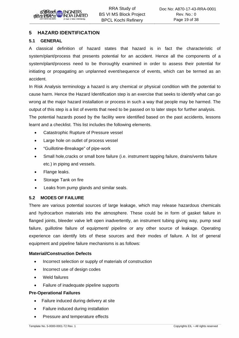
5 HAZARD IDENTIFICATION
5.1 GENERAL
A classical definition of hazard states that hazard is in fact the characteristic of
system/plant/process that presents potential for an accident. Hence all the components of a
system/plant/process need to be thoroughly examined in order to assess their potential for
initiating or propagating an unplanned event/sequence of events, which can be termed as an
accident.
In Risk Analysis terminology a hazard is any chemical or physical condition with the potential to
cause harm. Hence the Hazard Identification step is an exercise that seeks to identify what can go
wrong at the major hazard installation or process in such a way that people may be harmed. The
output of this step is a list of events that need to be passed on to later steps for further analysis.
The potential hazards posed by the facility were identified based on the past accidents, lessons
learnt and a checklist. This list includes the following elements.
Catastrophic Rupture of Pressure vessel
Large hole on outlet of process vessel
“Guillotine-Breakage” of pipe-work
Small hole,cracks or small bore failure (i.e. instrument tapping failure, drains/vents failure
etc.) in piping and vessels.
Flange leaks.
Storage Tank on fire
Leaks from pump glands and similar seals.
5.2 MODES OF FAILURE
There are various potential sources of large leakage, which may release hazardous chemicals
and hydrocarbon materials into the atmosphere. These could be in form of gasket failure in
flanged joints, bleeder valve left open inadvertently, an instrument tubing giving way, pump seal
failure, guillotine failure of equipment/ pipeline or any other source of leakage. Operating
experience can identify lots of these sources and their modes of failure. A list of general
equipment and pipeline failure mechanisms is as follows:
Material/Construction Defects
Incorrect selection or supply of materials of construction
Incorrect use of design codes
Weld failures
Failure of inadequate pipeline supports
Pre-Operational Failures
Failure induced during delivery at site
Failure induced during installation
Pressure and temperature effects

RRA Study of BS VI MS Block Project BPCL Kochi Refinery
Doc No: A870-17-43-RRA-0001 Rev. No.: 0
Page 20 of 38
Template No. 5-0000-0001-T2 Rev. 1 Copyrights EIL ¬ All rights reserved
Overpressure
Temperature expansion/contraction (improper stress analysis and support design)
Low temperature brittle fracture (if metallurgy is incorrect)
Fatigue loading (cycling and mechanical vibration)
Corrosion Failures
Internal corrosion (e.g. ingress of moisture)
External corrosion
Cladding/insulation failure (e.g. ingress of moisture)
Cathodic protection failure, if provided
Failures due to Operational Errors
Human error
Failure to inspect regularly and identify any defects
External Impact Induced Failures
Dropped objects
Impact from transport such as construction traffic
Vandalism
Subsidence
Strong winds
Failure due to Fire
External fire impinging on pipeline or equipment
Rapid vaporization of cold liquid in contact with hot surfaces
5.3 SELECTED FAILURE CASES
A list of selected failure cases was prepared based on process knowledge, engineering judgment,
experience, past incidents associated with such facilities and considering the general
mechanisms for loss of containment. A list of cases has been identified for the consequence
analysis study based on the following.
Cases with high chance of occurrence but having low consequence: Example of such
failure cases includes two-bolt gasket leak for flanges (1 x10⁻⁴ /year), seal failure (0.6
/year) for pumps, instrument tapping failure(5 x10⁻⁴ /year), etc. The consequence results
will provide enough data for planning routine safety exercises. This will emphasize the
area where operator's vigilance is essential.
Cases with low chance of occurrence but having high consequence (The example includes
Large hole on the outlet of pressure vessels (1 x10⁻⁶ /M-year to 1 x10⁻⁷ /M-year),
Catastrophic Rupture of Pressure Vessels (3 x10⁻⁶ /year), etc.)
This approach ensures at least one representative case of all possible types of accidental
failure events, is considered for the consequence analysis. Moreover, the list below
includes at least one accidental case comprising of release of different sorts of highly

RRA Study of BS VI MS Block Project BPCL Kochi Refinery
Doc No: A870-17-43-RRA-0001 Rev. No.: 0
Page 21 of 38
Template No. 5-0000-0001-T2 Rev. 1 Copyrights EIL ¬ All rights reserved
hazardous materials handled in the refinery. Although the list does not give complete failure
incidents considering all equipment’s, units, but the consequence of a similar incident
considered in the list below could be used to foresee the consequence of that particular
accident.
For selected credible failure scenarios and likely consequences for units under BS-VI MS Block ,
refer Section-6.
Note: References of frequencies are taken from:
Classification of Hazardous Locations, A.W.Cox, F.P.Lees and M.L.Ang, Published by the Institution of Chemical
Engineers, U.K.
Loss Prevention in the Process Industries, Hazard Identification, Assessment and Control, Frank.P.Lees, 2nd
Edition, Published by Butterworth-Heinemann, U.K.

RRA Study of BS VI MS Block Project BPCL Kochi Refinery
Doc No: A870-17-43-RRA-0001 Rev. No.: 0
Page 22 of 38
Template No. 5-0000-0001-T2 Rev. 1 Copyrights EIL ¬ All rights reserved
6 CONSEQUENCE ANALYSIS
6.1 GENERAL
Consequence analysis involves the application of the mathematical, analytical and computer
models for calculation of the effects and damages subsequent to a hydrocarbon / toxic release
accident.
Computer models are used to predict the physical behavior of hazardous incidents. The model
uses below mentioned techniques to assess the consequences of identified scenarios:
Modeling of discharge rates when holes develop in process equipment/pipe work
Modeling of the size & shape of the flammable/toxic gas clouds from releases in the
atmosphere
Modeling of the flame and radiation field of the releases that are ignited and burn as jet fire,
pool fire and flash fire
Modeling of the explosion fields of releases which are ignited away from the point of release
The different consequences (Flash fire, pool fire, jet fire and Explosion effects) of loss of
containment accidents depend on the sequence of events & properties of material released
leading to the either toxic vapor dispersion, fire or explosion or both.
6.2 CONSEQUENCE ANALYSIS MODELLING
6.2.1 DISCHARGE RATE
The initial rate of release through a leak depends mainly on the pressure inside the equipment,
size of the hole and phase of the release (liquid, gas or two-phase). The release rate decreases
with time as the equipment depressurizes. This reduction depends mainly on the inventory and
the action taken to isolate the leak and blow-down the equipment.
6.2.2 DISPERSION
Releases of gas into the open air form clouds whose dispersion is governed by the wind, by
turbulence around the site, the density of the gas and initial momentum of the release. In case of
flammable materials the sizes of these gas clouds above their Lower Flammable Limit (LFL) are
important in determining whether the release will ignite. In this study, the results of dispersion
modeling for flammable materials are presented LFL quantity.
6.2.3 FLASH FIRE
A flash fire occurs when a cloud of vapors/gas burns without generating any significant
overpressure. The cloud is typically ignited on its edge, remote from- the leak source. The
combustion zone moves through the cloud away from the ignition point. The duration of the flash
fire is relatively short but it may stabilize as a continuous jet fire from the leak source. For flash
fires, an approximate estimate for the extent of the total effect zone is the area over which the
cloud is above the LFL.
RRA Study of BS VI MS Block Project BPCL Kochi Refinery
Doc No: A870-17-43-RRA-0001 Rev. No.: 0
Page 23 of 38
Template No. 5-0000-0001-T2 Rev. 1 Copyrights EIL ¬ All rights reserved
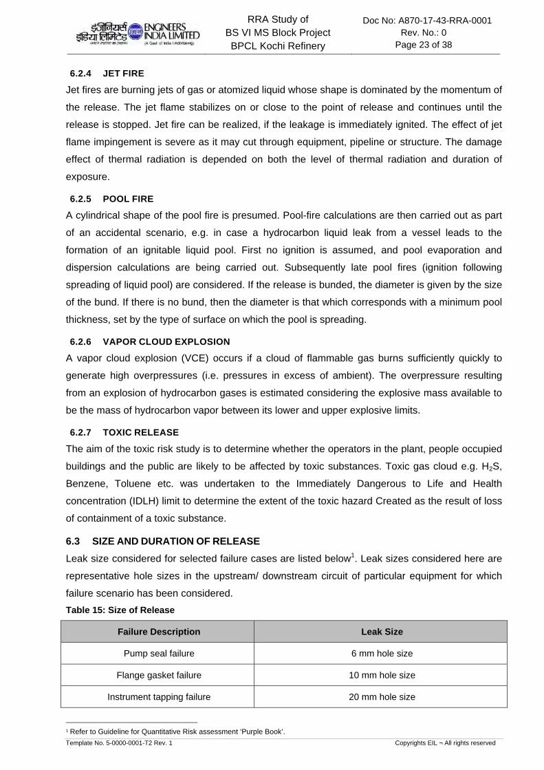
6.2.4 JET FIRE
Jet fires are burning jets of gas or atomized liquid whose shape is dominated by the momentum of
the release. The jet flame stabilizes on or close to the point of release and continues until the
release is stopped. Jet fire can be realized, if the leakage is immediately ignited. The effect of jet
flame impingement is severe as it may cut through equipment, pipeline or structure. The damage
effect of thermal radiation is depended on both the level of thermal radiation and duration of
exposure.
6.2.5 POOL FIRE
A cylindrical shape of the pool fire is presumed. Pool-fire calculations are then carried out as part
of an accidental scenario, e.g. in case a hydrocarbon liquid leak from a vessel leads to the
formation of an ignitable liquid pool. First no ignition is assumed, and pool evaporation and
dispersion calculations are being carried out. Subsequently late pool fires (ignition following
spreading of liquid pool) are considered. If the release is bunded, the diameter is given by the size
of the bund. If there is no bund, then the diameter is that which corresponds with a minimum pool
thickness, set by the type of surface on which the pool is spreading.
6.2.6 VAPOR CLOUD EXPLOSION
A vapor cloud explosion (VCE) occurs if a cloud of flammable gas burns sufficiently quickly to
generate high overpressures (i.e. pressures in excess of ambient). The overpressure resulting
from an explosion of hydrocarbon gases is estimated considering the explosive mass available to
be the mass of hydrocarbon vapor between its lower and upper explosive limits.
6.2.7 TOXIC RELEASE
The aim of the toxic risk study is to determine whether the operators in the plant, people occupied
buildings and the public are likely to be affected by toxic substances. Toxic gas cloud e.g. H2S,
Benzene, Toluene etc. was undertaken to the Immediately Dangerous to Life and Health
concentration (IDLH) limit to determine the extent of the toxic hazard Created as the result of loss
of containment of a toxic substance.
6.3 SIZE AND DURATION OF RELEASE
Leak size considered for selected failure cases are listed below1. Leak sizes considered here are
representative hole sizes in the upstream/ downstream circuit of particular equipment for which
failure scenario has been considered.
Table 15: Size of Release
Failure Description Leak Size
Pump seal failure 6 mm hole size
Flange gasket failure 10 mm hole size
Instrument tapping failure 20 mm hole size
1 Refer to Guideline for Quantitative Risk assessment ‘Purple Book’.

RRA Study of BS VI MS Block Project BPCL Kochi Refinery
Doc No: A870-17-43-RRA-0001 Rev. No.: 0
Page 24 of 38
Template No. 5-0000-0001-T2 Rev. 1 Copyrights EIL ¬ All rights reserved
Failure Description Leak Size
Large Hole in the Piping 50 mm, complete rupture of 2” drain line at the Process
vessel outlet
Catastrophic Rupture Complete Rupture of the Pressure Vessels
The discharge duration is taken as 10 minutes for continuous release scenarios as it is
considered that it would take plant personnel about 10 minutes to detect and isolate the leak2.
6.4 DAMAGE CRITERIA
In order to appreciate the damage effect produced by various scenarios, physiological/physical
effects of the blast wave, thermal radiation or toxic vapor exposition are discussed.
6.4.1 LFL OR FLASH FIRE
Hydrocarbon vapor released accidentally will spread out in the direction of wind. If a source of
ignition finds an ignition source before being dispersed below lower flammability limit (LFL), a
flash fire is likely to occur and the flame will travel back to the source of leak. Any person caught
in the flash fire is likely to suffer fatal burn injury. Therefore, in consequence analysis, the distance
of LFL value is usually taken to indicate the area, which may be affected by the flash fire.
Flash fire (LFL) events are considered to cause direct harm to the population present within the
flammability range of the cloud. Fire escalation from flash fire such that process or storage
equipment or building may be affected is considered unlikely.
6.4.2 THERMAL HAZARD DUE TO POOL FIRE, JET FIRE AND FIRE BALL
Thermal radiation due to pool fire, jet fire or fire ball may cause various degrees of burn on human
body and process equipment. The damage effect due to thermal radiation intensity is tabulated
below.
Table 16: Damage Due to Incident Thermal Radiation Intensity
Incident Radiation Intensity
(Kw/M²) Type of Damage
37.5 Sufficient to cause damage to process equipment
32.0 Maximum flux level for thermally protected tanks containing flammable
liquid
12.5 Minimum energy required for piloted ignition of wood, melting of plastic
tubing etc.
8.0 Maximum heat flux for un-insulated tanks
4.0 Sufficient to cause pain to personnel if unable to reach cover within 20
2 Release duration is based on Chemical Process Quantitative Risk Analysis, CCPS.

RRA Study of BS VI MS Block Project BPCL Kochi Refinery
Doc No: A870-17-43-RRA-0001 Rev. No.: 0
Page 25 of 38
Template No. 5-0000-0001-T2 Rev. 1 Copyrights EIL ¬ All rights reserved
Incident Radiation Intensity
(Kw/M²) Type of Damage
seconds. However blistering of skin (1stdegree burns) is likely.
The hazard distances to the 37.5 kW/m2, 32 kW/m2, 12.5 kW/m2, 8 kW/m2 and 4 kW/m2 radiation
levels, selected based on their effect on population, buildings and equipment were modeled using
PHAST.
6.4.3 VAPOR CLOUD EXPLOSION
In the event of explosion taking place within the plant, the resultant blast wave will have damaging
effects on equipment, structures, building and piping falling within the overpressure distances of
the blast. Tanks, buildings, structures etc. can only tolerate low level of overpressure. Human
body, by comparison, can withstand higher overpressure. But injury or fatality can be inflicted by
collapse of building of structures. The damage effect of blast overpressure is tabulated below.
Table 17: Damage Effects of Blast Overpressure
Blast Overpressure (PSI) Damage Level
5.0 Major structure damage
3.0 Oil storage tank failure
2.5 Eardrum rupture
2.0 Repairable damage, pressure vessels remain intact, light
structures collapse
1.0 Window pane breakage possible, causing some injuries
The hazard distances to the 5 psi, 3 psi and 2 psi overpressure levels, selected based on their
effects on population, buildings and equipment were modeled using PHAST.
6.4.4 TOXIC HAZARD
The inhalation of toxic gases can give rise to effects, which range in severity from mild irritation of
the respiratory tract to death. Lethal effects of inhalation depend on the concentration of the gas
to which people are exposed and on the duration of exposure. Mostly this dependence is
nonlinear and as the concentration increases, the time required to produce a specific injury
decreases rapidly.
The hazard distances to Immediately Dangerous to Life and Health concentration (IDLH) limit is
selected to determine the extent of the toxic hazard Created as the result of loss of containment of
a toxic substance.

RRA Study of BS VI MS Block Project BPCL Kochi Refinery
Doc No: A870-17-43-RRA-0001 Rev. No.: 0
Page 26 of 38
Template No. 5-0000-0001-T2 Rev. 1 Copyrights EIL ¬ All rights reserved
6.5 CONSEQUENCE ANALYSIS FOR MS BLOCK
This section discusses the consequences of selected failure scenarios for the upcoming BS VI
MS Block and associated offsite facilities. The consequence distances are reported in tabular
form for all weather conditions in Annexure-I and are represented graphically in Annexure-II for
the all failure scenarios in a unit for worst case weather conditions.
6.5.1 NHT
NOTE: Refer Figures 6.5.1.1 to 6.5.1.5 in Annexure-II
Instrument Tapping Failure at Feed Charge Pump: From the results of consequence analysis it is
observed that the LFL hazardous dispersion zone may reach upto 86 m from the source and may
extend beyond the B/L on the southern side. The 37.5 & 12.5 KW/m2 radiation intensities may
have effect distances of 61m and 72m respectively and may cause damage and secondary
effects within the unit. The 5 & 3 psi blast wave may extend up to a distance of 101 m & 110 m
respectively and may partially affect the adjacent VGO/HDS unit to the west and the upcoming
sub-station towards the southern side in case the scenario outcome is realized.
Large hole in the bottom of Reactor Product Separator: From the event outcome of the selected
failure scenario it can be observed that LFL may reach up to a distance of 211 m. The LFL
hazardous zone may extend beyond the plant boundary on the eastern and southern side. The
radiation intensity from 37.5kw/m2 Jet fire may affect a significant portion of the unit. The 5 & 3 psi
blast wave may reach up to a distance of 270 m & 292 m respectively and may cross the complex
boundary on the eastern side. Further affect may be noticed on the adjacent VGO/HDS on the
western side, SWS/ARU, SRU, Fuel oil tanks, S/S-1, SRR-2, gate house on the northern side,
part of new ISOM unit, new SRR and new substation on the southern side.
The toxic H2S impact distance for 100ppm cloud may not be realized in case of this scenario.
Recycle Compressor Instrument Tapping Failure: From the incident outcome analysis, it can be
observed that LFL and the subsequent consequences are largely restricted to the vicinity of the
leak. There may be possibility of localized radiation/blast overpressure damage which may cause
escalation.
Large Hole on bottom outlet of Stripper: From the consequence results and graphs of the selected
failure scenario, it can be observed that LFL may extend up to a distance of 92m and may be
realized beyond the unit boundary. The jet fire radiation intensities of 37.5 and 12.5 kW/m2 may
affect major part of the unit and may cause escalation. The 5 & 3 psi blast wave may reach up to
a distance of 112 m & 120 m respectively and extend beyond the Complex boundary on the
Southern side.
Splitter Reflux Pump Instrument tapping failure: From the consequence analysis of this high
frequency failure scenario, it is observed that LFL may extend beyond plant unit boundaries on

RRA Study of BS VI MS Block Project BPCL Kochi Refinery
Doc No: A870-17-43-RRA-0001 Rev. No.: 0
Page 27 of 38
Template No. 5-0000-0001-T2 Rev. 1 Copyrights EIL ¬ All rights reserved
the northern side of the unit. The jet fire radiation of 37.5 KW/m2 and 12.5 KW/m2 intensities are
restricted within the unit boundary and may cause escalation due to subsequent domino effects,
if realized . The 5 & 3 psi blast wave may reach up to a distance of 154 m & 167 m respectively
and may affect the equipment’s and piping in the unit leading to escalation. The blast waves may
also be realized beyond the complex boundary on the eastern side. The existing SWS/ARU
Substation S/S-1 and VGO/HDS may get affected depending on the prevailing conditions at the
time of release.
6.5.2 CCR
NOTE: Refer Figures 6.5.2.1 to 6.5.2.5 in Annexure-II
Instrument tapping failure at Separator Pumps: From the incident outcome analysis of this failure
scenario, it is observed that LFL distance of up to 79m may be realized beyond the unit
boundaries. The jet fire thermal radiation intensities of 37.5 and 12.5 kW/m2may be realized up to
a distance of 61 m and 73 m respectively and may lead to localized damage and escalation. In
case of no immediate ignition, the released material is expected to form a pool and the damage
due to radiation of similar intensities as jet fire may cause localized damage. The 5 & 3 psi blast
waves may have an effect zone of 98 m and 91m respectively and may affect the adjacent
VGO/HDS unit. Depending on the location of pump there is a possibility of upcoming ISOM unit
getting affected by these blast waves.
The toluene IDLH concentration of 500ppm may have a maximum effect distance of 491 m and
may affect onsite facilities such as chemical ware house, SRR-2, gate house, QC lab,
maintenance Ware house, SRR-3, and Substation (S/S-1) on the northern and eastern side of the
unit with a possibility of crossing the complex boundary on the northern and southern side and
may be further realized beyond the main road on the eastern side, based on orientation of the
leak and the prevalent weather conditions at the time of release.
In case of ethyl benzene IDLH toxic effect distances of 800 ppm for the worst case scenario may
be realized upto 236m and may affect a majority of facilities mentioned above.
Instrument tapping failure at Net gas compressor 2nd stage: From the graphs and table of incident
outcome analysis it is observed that the consequences are restricted within immediate vicinity of
loss of containment.
Instrument tapping failure in Reformate product pump : From the consequence modeling of the
selected failure scenario, it was observed that LFL may spread up to a distance of 72 m affecting
adjacent unit partially. The jet fire thermal radiation intensities of 37.5 and 12.5 kW/m2 may have
effect distances of 51m and 61 m respectively and may cause localized damage if realized. The
pool fire thermal radiation intensities of 37.5 and 12.5 kW/m2may have effect distances of 30 m
and 37m respectively and may cause localized damage if realized. The 5 & 3 psi blast wave may

RRA Study of BS VI MS Block Project BPCL Kochi Refinery
Doc No: A870-17-43-RRA-0001 Rev. No.: 0
Page 28 of 38
Template No. 5-0000-0001-T2 Rev. 1 Copyrights EIL ¬ All rights reserved
have an effect zone 85 m & 91 m respectively and may cause localized damage and possible
escalation.
The toluene IDLH concentration of 500ppm may have its effect up to a distance of 297 m and
may affect chemical ware house, SRR-2, gate house, QC lab, maintenance Ware house, SRR-3,
and Substation (S/S-1) on the northern and eastern side of the unit with a possibility of crossing
the complex boundary on the northern and southern side and extend beyond the main road on
the eastern side, based on orientation of the leak and the most prevalent weather conditions.
In case of ethyl benzene IDLH toxic effect distances of 800 ppm for the worst case scenario may
be realized upto 176m and may also have an affect on facilities mentioned above.
Large Hole in bottom Outlet of De-butanizer Receiver: From the incident outcome analysis of this
failure scenario, it is observed that LFL distance of up to 117 m may not be realized beyond the
complex boundaries. The radiation intensities of 37.5 KW/m2 and 12 KW/m2 due to jet fire in the
range of 110 m and 94 m respectively may have a bearing on the plant structures and equipment
depending on the orientation of leak and may lead to escalation. The 5 & 3 psi blast waves may
be experienced up to a distance of 138 m & 148 m respectively. The effect of blast waves may be
noticed on the adjacent VGO/HDS on the western side, SWS/ARU, SRU, S/S-1, SRR-2 on the
northern side, if realized.
Instrument tapping failure at De-butanizer Overhead Pumps: From the consequence results and
graphs of the selected failure scenario, it was observed that LFL may spread up to a distance of
47 m and may cross the unit boundary. The jet fire thermal radiation intensities of 37.5 and 12.5
kW/m2 intensity may have an effect zone of 56 m and 48 m respectively and may affect
equipment and structures inside the unit lead to escalation. The upcoming substation on the
southern side may be subjected to these radiation intensities depending upon the siting of the
equipment in the unit. The 5 & 3 psi blast wave effect zone may be realized up to a distance of 56
m & 51 m respectively from the source point possibly affecting the equipment and piping inside
unit leading to domino effects. Further, affect of these blast waves may also be noticed on the
upcoming substation on the southern side.
6.5.3 ISOMERIZATION UNIT
NOTE: Refer Figures 6.5.3.1 to 6.5.3.5 in Annexure-II
Instrument Tapping Failure at Charge Pump: From the consequence results and graphs of the
selected failure scenario, it was observed that LFL may be realized up to a distance of 87 m from
the point of loss of containment. The jet fire thermal radiation intensities of 37.5 and 12.5
kW/m2may be experienced up to a distance of 61m and 72 m respectively. These hazardous
intensities have a potential to affect major portion of the unit and also affect the adjacent NHT-
CCR unit depending on the release orientation. The 5 & 3 psi pressure wave effect zones can be

RRA Study of BS VI MS Block Project BPCL Kochi Refinery
Doc No: A870-17-43-RRA-0001 Rev. No.: 0
Page 29 of 38
Template No. 5-0000-0001-T2 Rev. 1 Copyrights EIL ¬ All rights reserved
experienced at a distance of 102 m & 110 m respectively from the source point. Units such as
NHT/CCR, VGO/HDS, and Upcoming SRR may be subjected to varying degrees of damage if
realized.
Large Hole on bottom outlet of Separator drum: From the incident outcome of the selected failure
scenario, it was observed that LFL may spread up to a distance of 236 m from the point of loss of
containment and may be realized beyond the complex boundary on the eastern side. The jet fire
thermal radiation intensities of 37.5 and 12.5 kW/m2 may spread up to a distance of 118 m and
141 m respectively may affect the upcoming SRR on the eastern side, adjacent NHT CCR and
VGO/HDS unit partially. The 5 & 3 psi blast wave effect zone may be up to a distance of 277 m &
294 m respectively from the source point and may affect proposed & existing NHT/CCR,
ARU/SWS, F.O tanks, VGO/HDS, Low sulphur diesel tanks in northern side, DHDS Substation,
Control room, S/S-2, SRR-1 on western side, the New boiler house, Nitrogen storage area, air
compressor, Cooling tower, CWPS caustic tank on the southern side. Towards the eastern side
the blast waves may have an effect zone well beyond the complex boundary. The pool fire
thermal radiation intensity of 12.5 kW/m2 may spread up to a distance of 39 m which is not
expected to affect any equipment beyond unit battery limit.
Instrument Tapping Failure at make-up gas Compressor: From the consequence results and
graphs of the selected failure scenario, it was observed that LFL may spread up to a distance of
25 m. The effect of jet fire thermal radiation intensity of 12.5 KW/m2 and 5 & 3 psi blast waves are
largely localized and restricted within the unit with a possibility of a domino effect if the outcome is
realized.
20mm leak at Isomerate Product-Stabilizer outlet line: From the consequence results and graphs
of the selected failure scenario, it was observed that LFL may extend up to a distance of 87 m and
may be realized beyond the unit boundaries. The jet fire thermal radiation intensities of 37.5 and
12.5 kW/m2 may spread up to a distance of 51m and 61 m respectively and may affect the
equipments in the unit and escalate. The 5 & 3 psi blast wave may spread up to a distance of 104
m & 112 m respectively from the source point and may affect the adjacent NHT/CCR units and
upcoming auxiliary facilities. However the blast waves may not be expected to be realized beyond
the complex boundaries.
Instrument Tapping Failure at Stabilizer Reflux Pump: From the consequence results and graphs
of the selected failure scenario, it was observed that LFL may be realized up to a distance of
42 m. The jet fire thermal radiation intensities of 37.5 and 12.5 kW/m2 may be experienced up to a
distance of 46 m and 54 m respectively affecting the equipments and structures within the units.
The 5 & 3 psi blast waves up to a distance of 51 m & 55 m respectively from the point of loss of
containment and may partially affect the equipments in NHT CCR which may result in escalation.
RRA Study of BS VI MS Block Project BPCL Kochi Refinery
Doc No: A870-17-43-RRA-0001 Rev. No.: 0
Page 30 of 38
Template No. 5-0000-0001-T2 Rev. 1 Copyrights EIL ¬ All rights reserved
6.5.4 OFFSITES
NHT Feed Tank on Fire: From the graph of this scenario, it is observed that the pool fire radiation
effect zone of 8KW/M2 may not be expected to affect the adjacent tanks for the prevailing
weather conditions.
Instrument tapping Failure at NHT feed pumps: From the Incident outcome analysis of this
scenario it is observed that the tanks YT-903 may be affected by 32KW/m2 & 8KW/m2 jet fire
radiation intensities. Also the tank YT-903 may be subjected to direct flame impingement which
may lead to hazardous secondary effects. The 5 & 3psi blast waves may affect the existing
control room on the south, the new tank farm, and the existing NHT/CCR feed tank farm if
realized.

RRA Study of BS VI MS Block Project BPCL Kochi Refinery
Doc No: A870-17-43-RRA-0001 Rev. No.: 0
Page 31 of 38
Template No. 5-0000-0001-T2 Rev. 1 Copyrights EIL ¬ All rights reserved
7 OBSERVATIONS & RECOMMENDATIONS
The detailed consequence analysis of release of hydrocarbon in case of major credible scenarios
are modeled in terms of release rate, dispersion, flammability and toxic characteristics, which
have been discussed in detail in the report. The Observations and recommendations arising out of
the Rapid Risk analysis study for units under upcoming MS block are summarized below:
NHT/CCR
Low frequency credible failure scenarios for NHT/CCR units are modeled and it is observed
that for large hole in Stripper bottom(NHT), De-Butanizer receiver(CCR), the radiation &
explosion effect zones may extend beyond the unit battery limits & may affect the nearby
units depending upon the prevalent weather condition and presence of ignition source at the
time of release. In case of Large hole in bottom of Reactor product separator (NHT) the LFL
hazardous zone may extend beyond the Complex boundary on the eastern side. The 5 & 3
psi may affect the adjacent VGO/HDS on the western side, SWS/ARU, SRU, Fuel oil tanks,
S/S-1, SRR-2, gate house on the northern side, new ISOM unit, existing NHT/CCR/ISOM,
upcoming SRR and upcoming substation on the southern side. The blast effects may also be
realized beyond the complex boundary well beyond the main road towards the eastern side
depending on the conditions of prevailing at the time of release. The potential outcomes of
large hole may have a significant impact onsite and offsite. However, Owing to the remote
possibility of realizing the large hole scenario (in the order of 1 x10⁻⁶ /M-year to 1 x10⁻⁷/M-
year) and its damaging effects. It is recommended to:
Include these scenarios to the already existing Disaster Management Plan (DMP) &
Emergency Response Plan (ERP).
Provide adequate number of hydrocarbon at suitable locations within these units for
early leak detection and inventory isolation.
In case of the Instrument tapping failure at Separator Pumps and Reformate product pump
instrument tapping failure of CCR, the jet radiation effect distances may affect the major part
of the unit and may lead to escalation. The blast overpressures of 5 and 3 psi may impact the
adjacent VGO/HDS, New ISOM, new substation and new SRR based on prevailing wind
conditions and direction of leak. However, the overpressure effects are observed to be largely
restricted within the complex boundaries. The toluene IDLH concentration of 500ppm may
have its effect up to a distance of 423 m and 345m in case of failures at separator pump and
reformate product pump respectively. Based on orientation of the leak and the more prevalent
weather conditions. The toxic affect may be experienced at chemical ware house, SRR-2,
gate house, fire station, QC lab, maintenance ware house, SRR-3, and Substation (S/S-1) on

RRA Study of BS VI MS Block Project BPCL Kochi Refinery
Doc No: A870-17-43-RRA-0001 Rev. No.: 0
Page 32 of 38
Template No. 5-0000-0001-T2 Rev. 1 Copyrights EIL ¬ All rights reserved
the northern and eastern side of the unit with a possibility of crossing the complex boundary
on the northern and southern side and extending beyond the main road on the eastern side.
In order to assess the risk to public due to loss of containment from the toluene containing
streams, risk analysis is carried out. For public, the Individual risk contour of 1 x 10⁻⁶/Avg yr
and lower (Negligible risk) is considered to demonstrate broadly acceptable region. From the
preliminary risk evaluation for credible failure cases within NHT/CCR & ISOM, it is seen that
the IR contour of 1 x 10⁻⁶ /Avg year (Refer fig 6.5.1.A) is within the complex boundary.
However a detailed Quantitative risk assessment (QRA) shall be carried out at detail
engineering stage for any further analysis.
Based on the above observations the following is recommended.
Provide adequate number of hydrocarbon at suitable locations within the unit and at the periphery
of the unit for early leak detection. Also mitigating procedures such emergency shutdown of
rotating equipments, quick isolation of inventories shall be developed as a part of the Emergency
response plan & Disaster Management Plan to address the concerns of high frequency failure
scenarios.
It is suggested to locate the CCR separator and related equipments, De-butanizer & reformate
pump towards the western side of the piperack to maintain as much distance as possible from
compound wall.
As the Quality Control lab may be affected by the toxic concentration of Toluene, suitable no. of
breathing apparatus may be provided to use in case of emergency based on detection or
emergency guidelines.
ISOM
Low frequency credible failure scenarios for ISOM units are modeled and it is observed that in
the event of large hole on bottom outlet of Separator Drum, radiation& explosion effect zones may
get extended beyond the units battery limits & affect nearby facilities including SRR-2, SRR-
3,Substation, gate house, SRR-3, and Substation (S/S-1), fuel oil tanks, low sulphur diesel tanks
and high sulphur diesel tanks on the northern side of the unit with a possibility of crossing the
complex boundary on the eastern side based on orientation of the leak and the most prevalent
weather conditions. As the possibility of realization of this scenario is extremely remote the
following is recommended.
The scenario may be utilized for Disaster management plant & Emergency Response Plan.

RRA Study of BS VI MS Block Project BPCL Kochi Refinery
Doc No: A870-17-43-RRA-0001 Rev. No.: 0
Page 33 of 38
Template No. 5-0000-0001-T2 Rev. 1 Copyrights EIL ¬ All rights reserved
High frequency credible failure scenarios for ISOM are also modeled. In the event of
instrument tapping failure of charge pumps, 20mm leak in the isomerate product-Stabilizer
outlet, it was observed that LFL may not extend beyond the complex boundary. The 5 & 3 psi
blast wave may affect the adjacent NHT/CCR units and upcoming facilities and may not
extend beyond the complex boundary. Based on the observations the following is
recommended.
Provide sufficient number of hydrocarbon detectors within the ISOM unit for early leak detection and
develop procedures for stopping of rotating equipments and quicker inventory isolation.
OFFSITES
Instrument tapping Failure at NHT feed pumps: From the Incident outcome analysis of this
scenario it is observed that the tanks YT-903 may be affected by 8KW/m2 and 32 KW/m2 jet
fire radiation intensities. Also the tank YT-903 may be subjected to direct flame impingement
and may lead to a domino effect in case of orientation of jet towards the tank. The 5 & 3psi
blast waves may affect the existing control room on the south, the new tank farm, and the
existing NHT/CCR feed tank farm based on the prevailing wind conditions and presence of
ignition sources at the time of leak.
The low operating frequency of the pump may be taken into consideration as a mitigating
factor for reduction in the probability of the realization of this scenario.
Based on the preceding observations the following is recommended:
As existing Tank YT-903 may be subjected to direct flame impingement the new pumps and
any leakage points such as flanges etc., be located atleast 40m away from the tank.
Review the suitability of active fire protection for this Tankage system for protection against
32KW/m2 radiation intensity.
The active fire protection system provided for storage tanks (YT-903/905) are to be regularly
checked for prompt action on actuation.
As the control room may not be exposed to LFL, but may be partially subjected to blast
overpressures, based on the prevailing site conditions and presence of ignition sources,
ensure suitable mitigation by early leak detection and automated inventory isolation.

RRA Study of BS VI MS Block Project BPCL Kochi Refinery
Doc No: A870-17-43-RRA-0001 Rev. No.: 0
Page 34 of 38
Template No. 5-0000-0001-T2 Rev. 1 Copyrights EIL ¬ All rights reserved
a) Recommendations for Construction Safety during execution of the MS Block
Project b) General Recommendations
Proper checking of contract people for smoking or inflammable materials to be ensured at
entry gates to avoid presence of any unidentified source of ignition.
Ensure vehicles entering the Refinery are fitted with spark arrestors, as a mandatory item.
In order to prevent secondary incident arising from any failure scenario, it is recommended
that sprinklers and other protective devices provided on the tanks are regularly checked to
ensure these are functional.
Mock drills to be organized at organization level to ensure preparation of the personnel’s
working in Refinery for handling any hazardous situation.
For positively pressurized building, both Hydrocarbon & Toxic detectors need to be placed
at suction duct of HVAC. HVAC to be tripped automatically in event of the detection of any
Hydrocarbon / toxic material by detector.
Ensure usage of safer oxidizing agents (Chlorine free) in Cooling Water circuit.
c) Mitigating Measures
Mitigating measures are those measures in place to minimize the loss of containment event and,
hazards arising out of Loss of containment. These include:
Measures for controlling / minimization of Ignition sources inside the Refinery complex.
Active and Passive Fire Protection for critical equipment’s and major structures
Effective Emergency Response plans to be in place.
Water spray/curtain system may be utilized as means to restrict the hazardous cloud
movement in case of a leak.
d) Ignition Control
Ignition control will reduce the likelihood of fire events. This is the key for reducing the risk
within facilities processing flammable materials. As part of mitigation measure it strongly
recommended to consider minimization of the traffic movement within the Refinery.
e) Escape Routes
Ensure sufficient escape routes from the site are available to allow redundancy in escape
from all areas.
Ensure sufficient number of windsocks throughout the site to ensure visibility from all
locations. This will enable people to escape upwind or crosswind from flammable / toxic
releases.
Provide sign boards marking emergency/safe roads to be taken during any exigencies.
f) Preventive Maintenance for Critical Equipment’s
In order to reduce the failure frequency of critical equipment’s, the following are
recommended:

RRA Study of BS VI MS Block Project BPCL Kochi Refinery
Doc No: A870-17-43-RRA-0001 Rev. No.: 0
Page 35 of 38
Template No. 5-0000-0001-T2 Rev. 1 Copyrights EIL ¬ All rights reserved
a. High head pumps and Compressors, which are in flammable / toxic services, are
needed to be identified.
i. Their seals, instruments and accessories are to be monitored closely
ii. A detailed preventive maintenance plan to be prepared and followed.
b. Surge Drums & Reflux drums and high inventory vessels whose rupture may lead
to massive consequences are needed to be identified and following to be ensured:
i. Monitoring of vessel internals during shut down.
ii. A detailed preventive maintenance plan to be prepared and followed.
g) Others
Ensure removal of hammer blinds from the process facilities, if any.
Closed sampling system to be considered for pressurized services like LPG, Propylene
etc.
Recommended to use portable HC detector during sampling and maintenance etc.
Provide breathing apparatus at strategic locations inside Refinery.

RRA Study of BS VI MS Block Project BPCL Kochi Refinery
Doc No: A870-17-43-RRA-0001 Rev. No.: 0
Page 36 of 38
Template No. 5-0000-0001-T2 Rev. 1 Copyrights EIL ¬ All rights reserved
8 GLOSSARY
CASUALTY Someone who suffers serious injury or worse i.e. including fatal
injuries. As a rough guide fatalities are likely to be half the total
casualties. But this may vary depending on the nature of the event.
HAZARD A chemical or physical condition with the potential of causing
damage.
FLAMMABILITY LIMITS In fuel-air systems, a range of compositions exists inside which a
(UFL – LFL) flame will propagate substantial distance from an
ignition source. The limiting fuel concentrations are termed as
Upper flammability or explosives limit (Fuel concentrations
exceeding this are too rich) and Lower flammability or explosives
limit (Fuel concentrations below this are too lean).
FLASH FIRE The burning of a vapor cloud at very low flame propagation speed.
Combustion products are generated at a rate low enough for
expansion to take place easily without significant overpressure
ahead or behind the flame front. The hazard is therefore only due to
thermal effects.
OVERPRESSURE Maximum pressure above atmosphere pressure experiences during
the passage of a blast wave from an explosion expressed in this
report as pounds per square inch (psi).
EXPLOSION A rapid release of energy, which causes a pressure discontinuity or
shock wave moving away from the source. An explosion can be
produced by detonation of a high explosive or by the rapid burning
of a flammable gas cloud. The resulting overpressure is sufficient to
cause damage inside and outside the cloud as the shock wave
propagation into the atmosphere beyond the cloud. Some authors
use the term deflagration for this type of explosion
DOMINO EFFECT The effect that loss of containment of one installation leads to loss
of containment of other installations
EVENT TREE A logic diagram of success and failure combinations of events used
to identify accident sequences leading to all possible consequences
of a given initiating event.
TLV “Threshold limit value” is defined as the concentration of the
substance in air that can be breathed for five consecutive 8 hours
work day (40 hours work week) by most people without side effect.
STEL “Short Term Exposure Limit” is the maximum permissible average
exposure for the time period specified (15 minutes).
RRA Study of BS VI MS Block Project BPCL Kochi Refinery
Doc No: A870-17-43-RRA-0001 Rev. No.: 0
Page 37 of 38
Template No. 5-0000-0001-T2 Rev. 1 Copyrights EIL ¬ All rights reserved
IDLH “Immediate Dangerous to Life and Health” is the maximum
concentration level from which one could escape within 30 minutes
without any escape impairing symptoms.
PASQUILL CLASS Classification to qualify the stability of the atmosphere, indicated by
a letter ranging from A, for very unstable, to F, for stable.
FREQUENCY The number of times an outcome is expected to occur in a given
period of time.

RRA Study of BS VI MS Block Project BPCL Kochi Refinery
Doc No: A870-17-43-RRA-0001 Rev. No.: 0
Page 38 of 38
Template No. 5-0000-0001-T2 Rev. 1 Copyrights EIL ¬ All rights reserved
9 REFERENCES
1. Classification of hazardous locations, A. W. Cox, F. P. Lees and M. L. Ang, Published by
the Institute of Chemical engineers, U. K.
2. The reference manual, Volume-II, Creemer & Warner Ltd. U. K. (Presently Entec).
3. Risk analysis of six potentially hazardous industrial objects in the Rijnmond area; A pilot
study. A report to the Rijnmond Public Authority. D. Riedel publishing company, U. K.
4. Loss prevention in the process industries, Hazard identification, Assessment and Control,
Frank. P. Lees (Vol. I, II & III), (2nd edition ) ,Published by Butterworth-Heinemann, U. K.
5. AICHE, CCPS, Chemical process Quantitative Risk Analysis(2nd edition)
6. Guideline for Quantitative Risk assessment, ‘Purple book’.( 2005)

RRA Study of BS VI MS Block Project BPCL Kochi Refinery
Doc No: A870-17-43-RRA-0001 Rev. No.: 0
Template No. 5-0000-0001-T2 Rev. 1 Copyrights EIL ¬ All rights reserved
ANNEXURE I
CONSEQUENCE ANALYSIS HAZARD DISTANCES
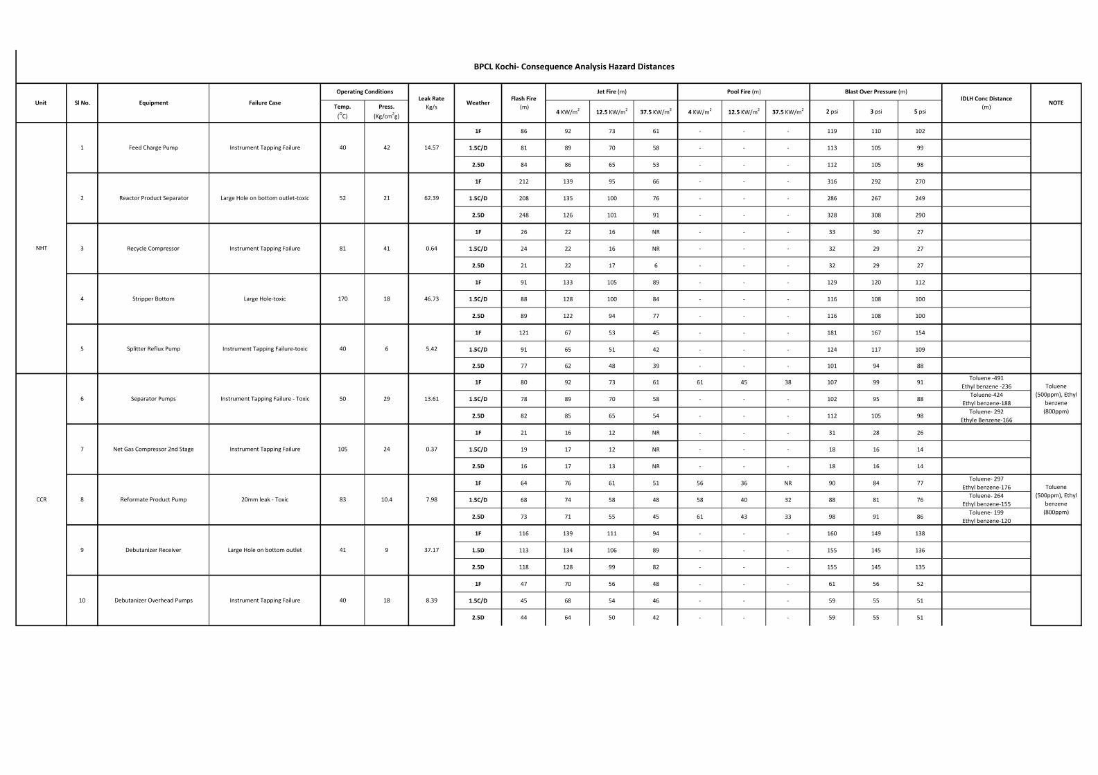
Temp.
(OC)
Press.
(Kg/cm2g)4 KW/m2 12.5 KW/m2 37.5 KW/m2 4 KW/m2 12.5 KW/m2 37.5 KW/m2 2 psi 3 psi 5 psi
1F 86 92 73 61 - - - 119 110 102
1.5C/D 81 89 70 58 - - - 113 105 99
2.5D 84 86 65 53 - - - 112 105 98
1F 212 139 95 66 - - - 316 292 270
1.5C/D 208 135 100 76 - - - 286 267 249
2.5D 248 126 101 91 - - - 328 308 290
1F 26 22 16 NR - - - 33 30 27
1.5C/D 24 22 16 NR - - - 32 29 27
2.5D 21 22 17 6 - - - 32 29 27
1F 91 133 105 89 - - - 129 120 112
1.5C/D 88 128 100 84 - - - 116 108 100
2.5D 89 122 94 77 - - - 116 108 100
1F 121 67 53 45 - - - 181 167 154
1.5C/D 91 65 51 42 - - - 124 117 109
2.5D 77 62 48 39 - - - 101 94 88
1F 80 92 73 61 61 45 38 107 99 91Toluene -491
Ethyl benzene -236
1.5C/D 78 89 70 58 - - - 102 95 88Toluene-424
Ethyl benzene-188
2.5D 82 85 65 54 - - - 112 105 98Toluene- 292
Ethyle Benzene-166
1F 21 16 12 NR - - - 31 28 26
1.5C/D 19 17 12 NR - - - 18 16 14
2.5D 16 17 13 NR - - - 18 16 14
1F 64 76 61 51 56 36 NR 90 84 77Toluene- 297
Ethyl benzene-176
1.5C/D 68 74 58 48 58 40 32 88 81 76Toluene- 264
Ethyl benzene-155
2.5D 73 71 55 45 61 43 33 98 91 86Toluene- 199
Ethyl benzene-120
1F 116 139 111 94 - - - 160 149 138
1.5D 113 134 106 89 - - - 155 145 136
2.5D 118 128 99 82 - - - 155 145 135
1F 47 70 56 48 - - - 61 56 52
1.5C/D 45 68 54 46 - - - 59 55 51
2.5D 44 64 50 42 - - - 59 55 51
18
5.42
Toluene (500ppm), Ethyl
benzene (800ppm)
8.39
Debutanizer Receiver Large Hole on bottom outlet
50
9 37.17
29 13.61
24 0.37
10.4 7.98
Toluene (500ppm), Ethyl
benzene (800ppm)
Reactor Product Separator Large Hole on bottom outlet-toxic 52
Recycle Compressor Instrument Tapping Failure 81 41
21
46.73
0.64
14.57
62.39
105
10 Debutanizer Overhead Pumps
9 41
Instrument Tapping Failure 40
7
8 Reformate Product Pump 20mm leak - Toxic 83
Net Gas Compressor 2nd Stage Instrument Tapping Failure
3
42
6
1 Feed Charge Pump Instrument Tapping Failure 40
2
4 Stripper Bottom Large Hole-toxic 170 18
Separator Pumps Instrument Tapping Failure - Toxic
5 Splitter Reflux Pump Instrument Tapping Failure-toxic 40 6
Unit Sl No. Equipment Failure Case NOTEWeather
Jet Fire (m) Pool Fire (m) Blast Over Pressure (m)Leak Rate
Kg/sFlash Fire
(m)IDLH Conc Distance
(m)
Operating Conditions
CCR
NHT
BPCL Kochi- Consequence Analysis Hazard Distances

Temp.
(OC)
Press.
(Kg/cm2g)4 KW/m2 12.5 KW/m2 37.5 KW/m2 4 KW/m2 12.5 KW/m2 37.5 KW/m2 2 psi 3 psi 5 psi
Unit Sl No. Equipment Failure Case NOTEWeather
Jet Fire (m) Pool Fire (m) Blast Over Pressure (m)Leak Rate
Kg/sFlash Fire
(m)IDLH Conc Distance
(m)
Operating Conditions
BPCL Kochi- Consequence Analysis Hazard Distances
1F 87 91 72 61 - - - 119 110 102
1.5C/D 82 88 69 58 - - - 113 106 99
2.5D 86 85 65 53 - - - 112 105 98
1F 197 179 141 118 56 37 NR 287 265 245
1.5C/D 194 174 135 112 60 39 NR 270 252 235
2.5D 230 168 127 103 65 41 NR 311 293 276
1F 25 20 15 NR - - - 31 28 26
1.5C/D 22 20 15 NR - - - 30 28 26
2.5D 21 20 15 NR - - - 30 27 25
1F 87 77 61 51 - - - 122 113 104
1.5C/D 76 75 58 49 - - - 101 94 88
2.5D 83 72 55 45 - - - 111 104 98
1F 43 67 54 46 - - - 59 55 51
1.5C/D 41 64 51 44 - - - 58 54 50
2.5D 40 61 48 40 - - - 58 54 50
Temp.
(OC)
Press.
(Kg/cm2g)4 KW/m2 8 KW/m2 32 KW/m2 4 KW/m2 8 KW/m2 32 KW/m2 2 psi 3 psi 5 psi
1F 123 69 54 45 - - - 179 166 154
1.5C/D 87 67 52 43 - - - 113 106 99
2.5D 78 64 49 40 - - - 100 94 88
1F - - - - 54 30 NR - - -
1.5C/D - - - - 59 32 NR - - -
2.5D - - - - 67 36 NR - - -
ISOM
12 Separator Drum Large Hole on bottom outlet
13
40
Stabilizer Rflux Pump 60
Instrument Tapping Failure-toxic
H2 Make-up Compressor
13.63
Instrument Tapping Failure
1815
109 36.9
8.2414.5
8.22
0.77
19.1 57.21
7
Failure Case
5.9516 NHT FEED PUMP Instrument Tapping Failure
Leak RateKg/s
NOTE
40
17 NHT feed tank Tank on Fire 30 0.007 -
OFFSITE
Unit
Operating Conditions
WeatherFlash Fire
(m)
Jet Fire (m) Pool Fire (m) Blast Over Pressure (m)IDLH Conc Distance
(m)
Isomerate product separator outlet line
Instrument Tapping Failure
20mm leak 40
EquipmentSl No.
14
11 Charge Pumps 40 38

RRA Study of BS VI MS Block Project BPCL Kochi Refinery
Doc No: A870-17-43-RRA-0001 Rev. No.: 0
Template No. 5-0000-0001-T2 Rev. 1 Copyrights EIL ¬ All rights reserved
ANNEXURE II
FIGURES FOR CONSEQUENCE ANALYSIS OF MS BLOCK

Figure 6.5.1.1 A: NHT: Instrument Tapping Failure at Feed Charge Pump; Flash fire Distances (m)

Figure 6.5.1.1 B: NHT: Instrument Tapping Failure at Feed Charge Pump; Jet fire Distances (m)

Figure 6.5.1.1 C: NHT: Instrument Tapping Failure at Feed Charge Pump; Overpressure Distances (m)

Figure 6.5.1.2 A: NHT: Large hole of Reactor Product Separator ; Flash Fire Distances (m)

Figure 6.5.1.2 B: NHT: Large hole of Reactor Product Separator ; Jet Fire Distances (m)

Figure 6.5.1.2 C: NHT: Large hole of Reactor Product Separator; Over Pressure Distances (m)

Figure 6.5.1.3 A: NHT: Instrument Tapping Failure at Recycle Compressor; Flash Fire Distances (m)

Figure 6.5.1.3 B: NHT: Instrument Tapping Failure at Recycle Compressor; Jet Fire Distances (m)

Figure 6.5.1.3 C: NHT: Instrument Tapping Failure at Recycle Compressor; Over Pressure Distances (m)

Figure 6.5.1.4 A: NHT: Large Hole on bottom outlet of Stripper Bottom; Flash Fire Distances (m)

Figure 6.5.1.4 B: NHT: Large Hole on bottom outlet of Stripper Bottom ; Jet Fire Distances (m)

Figure 6.5.1.4 C: NHT: Large Hole on bottom outlet of Stripper Bottom ; Over Pressure Distances (m)

Figure 6.5.1.5 A: NHT: Instrument Tapping Failure of Splitter Reflux Pump; Flash Fire Distances (m)

Figure 6.5.1.5 B: NHT: Instrument Tapping Failure of Splitter Reflux Pump; Jet Fire Distances (m)
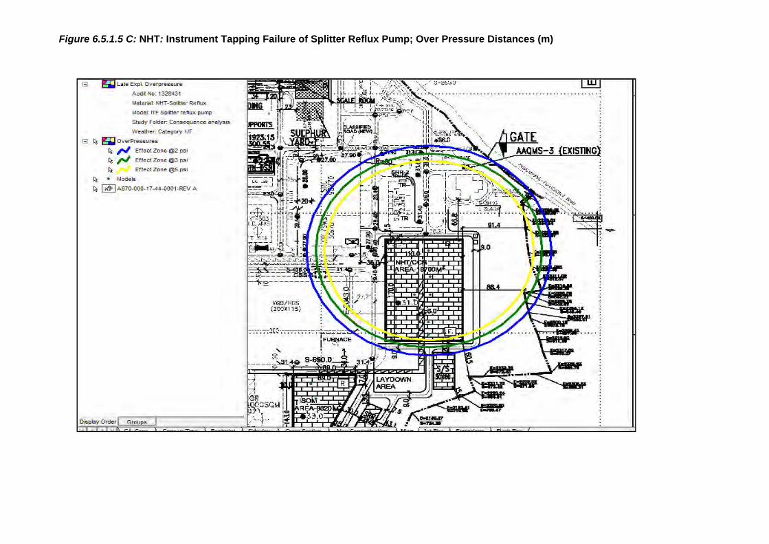
Figure 6.5.1.5 C: NHT: Instrument Tapping Failure of Splitter Reflux Pump; Over Pressure Distances (m)

Figure 6.5.2.1 A: CCR: Instrument Tapping Failure at Separator Pumps - Toxic; Flash Fire Distances (m)
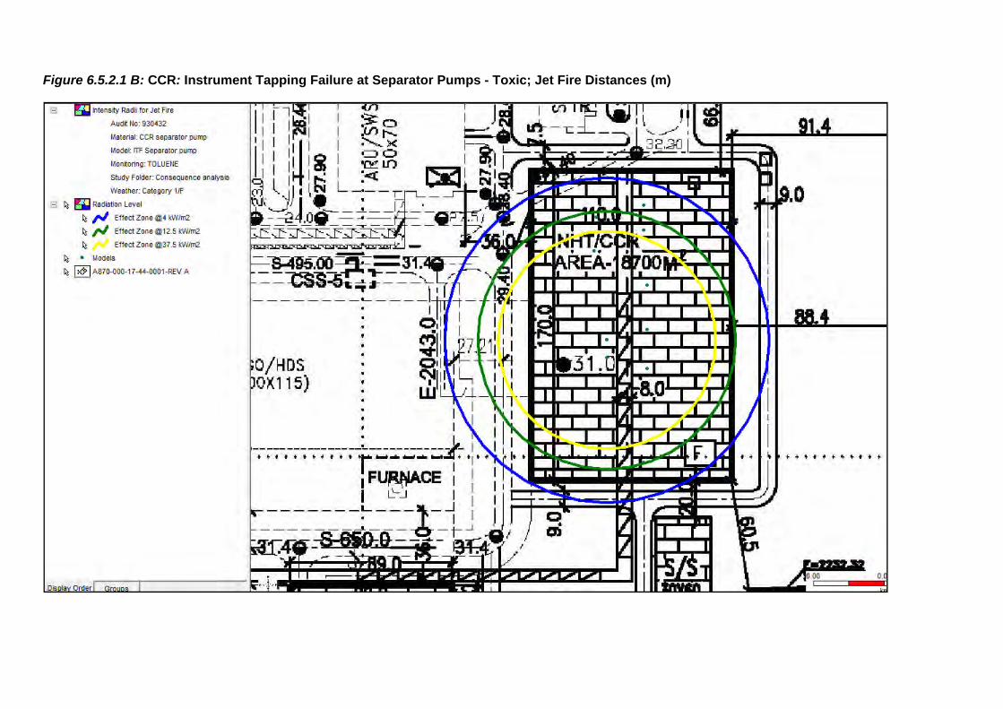
Figure 6.5.2.1 B: CCR: Instrument Tapping Failure at Separator Pumps - Toxic; Jet Fire Distances (m)

Figure 6.5.2.1 C: CCR: Instrument Tapping Failure at Separator Pumps - Toxic; Late Pool Fire Distances (m)

Figure 6.5.2.1 D: CCR: Instrument Tapping Failure at Separator Pumps - Toxic; Over Pressure Distances (m)

Figure 6.5.2.1 D: CCR: Instrument Tapping Failure at Separator Pumps - Toxic; Toluene IDLH Distances (m)-500ppm

Figure 6.5.2.2 A: CCR: Instrument Tapping Failure at Recycle Gas Compressor ; Flash Fire Distances (m)

Figure 6.5.2.2 B: CCR: Instrument Tapping Failure at Recycle Gas Compressor - Toxic; Jet Fire Distances (m)

Figure 6.5.2.2 C: CCR: Instrument Tapping Failure at Recycle Gas Compressor - Toxic; Overpressure Distances (m)

Figure 6.5.2.3 A: CCR : Instrument Tapping Failure in reformate product Pump ; Flash Fire Distances (m)

Figure 6.5.2.3 B: CCR: Instrument Tapping Failure in reformate product Pump - Toxic; Jet Fire Distances (m)

Figure 6.5.2.3 C: CCR: Instrument Tapping Failure in reformate product Pump; Pool fire Distances (m)

Figure 6.5.2.3 D: CCR: Instrument Tapping Failure in reformate product Pump; Overpressure Distances (m)

Figure 6.5.2.3 E: CCR: 20mm Leak in reformate product Pump - Toxic; Toluene IDLH Hazard Distances (m)-500ppm

Figure 6.5.2.4 A: CCR: Large Hole on the Bottom Outlet of De-butanizer Receiver; Flash Fire Distances (m)

Figure 6.5.2.4 B: CCR: Large Hole on the Bottom Outlet of De-butanizer Receiver; Jet Fire Distances (m)
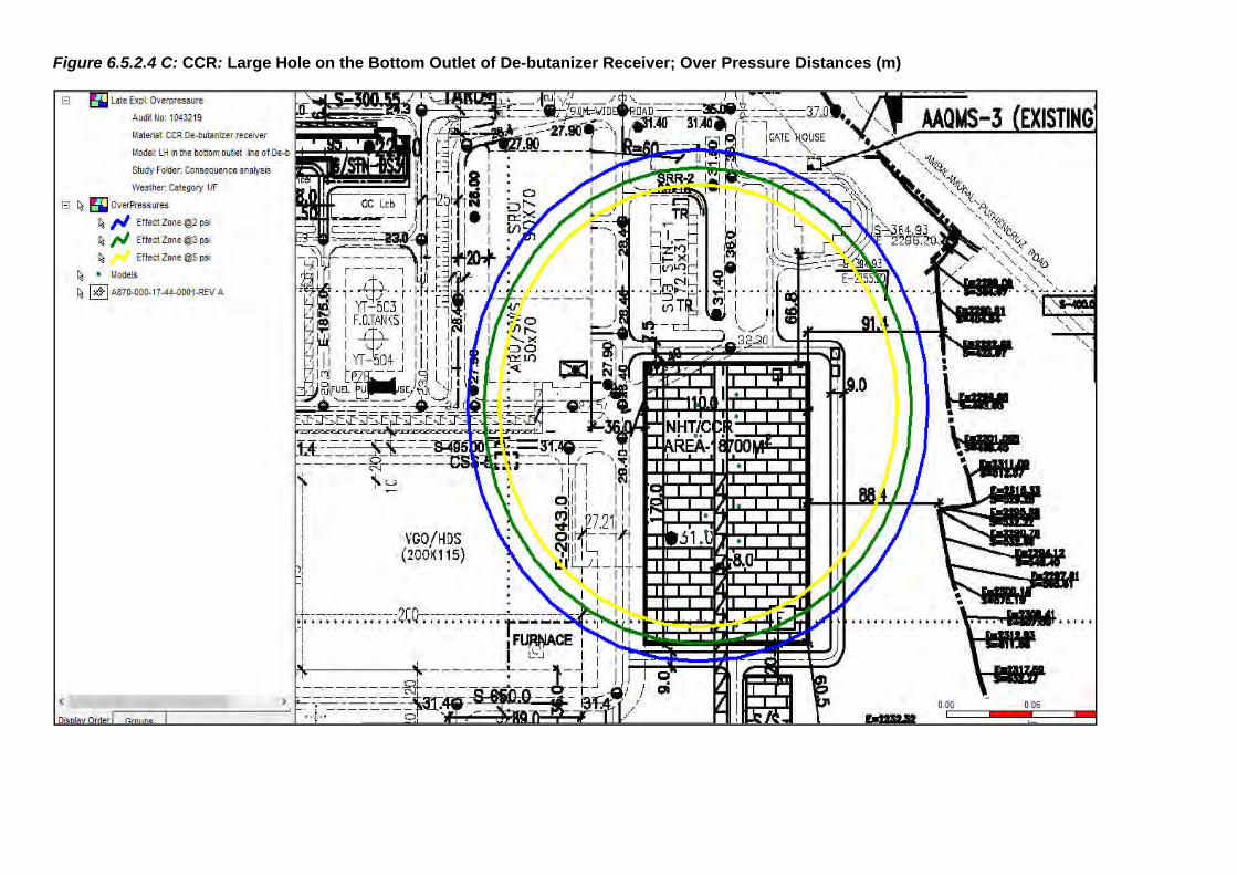
Figure 6.5.2.4 C: CCR: Large Hole on the Bottom Outlet of De-butanizer Receiver; Over Pressure Distances (m)

Figure 6.5.2.5 A: CCR: Instrument Tapping Failure at De-butanizer Overhead pumps; Flash Fire Distances (m)

Figure 6.5.2.5 B: CCR: Instrument Tapping Failure at De-butanizer Overhead pumps; Jet Fire Distances (m)

Figure 6.5.2.5 C: CCR: Instrument Tapping Failure at De-butanizer Overhead pumps; Overpressure Fire Distances (m)

Figure 6.5.3.1 A: ISOM: Instrument Tapping Failure at Charge Pump; Flash fire Distances (m)

Figure 6.5.3.1 B: ISOM: Instrument Tapping Failure at Charge Pump; Jet fire Distances (m)

Figure 6.5.3.1 C: ISOM: Instrument Tapping Failure at Charge Pump; Overpressure Distances (m)

Figure 6.5.3.2 A: ISOM: Large Hole on bottom outlet of Separator Bottom; Flash Fire Distances (m)

Figure 6.5.3.2 B: ISOM: Large Hole on bottom outlet of Separator Bottom; Jet Fire Distances (m)

Figure 6.5.3.2 C: ISOM: Large Hole on bottom outlet of Separator Bottom; Pool Fire Distances (m)

Figure 6.5.3.2 D: ISOM: Large Hole on bottom outlet of Separator Bottom; Overpressure Distances (m)

Figure 6.5.3.3 A: ISOM: Instrument Tapping Failure at Hydrogen make-up gas compressor; Flash Fire Distances (m)

Figure 6.5.3.3 B: ISOM: Instrument Tapping Failure at Hydrogen make-up gas compressor; Jet Fire Distances (m)

Figure 6.5.3.3 C: ISOM: Instrument Tapping Failure at Hydrogen make-up gas compressor; Overpressure Distances (m)

Figure 6.5.3.4 A: ISOM: 20mm leakage at Isomerate Product line; Flash Fire Distances (m)

Figure 6.5.3.4 B: ISOM: 20mm leakage at Isomerate Product line; Jet Fire Distances (m)

Figure 6.5.3.4 C: ISOM: 20mm leakage at Isomerate Product line; Overpressure Distances (m)

Figure 6.5.3.5 A: ISOM: Instrument Tapping Failure at Stabilizer reflux pump; Flash Fire Distances (m)

Figure 6.5.3.5 B: ISOM: Instrument Tapping Failure at Stabilizer reflux pump; Jet Fire Distances (m)

Figure 6.5.3.5 C: ISOM: Instrument Tapping Failure at Stabilizer reflux pump; Overpressure Distances (m)

RRA Study of BS VI MS Block Project BPCL Kochi Refinery
Doc No: A870-17-43-RRA-0001 Rev. No.: 0
Template No. 5-0000-0001-T2 Rev. 1 Copyrights EIL ¬ All rights reserved
ANNEXURE III
INDIVIDUAL RISK CONTOUR
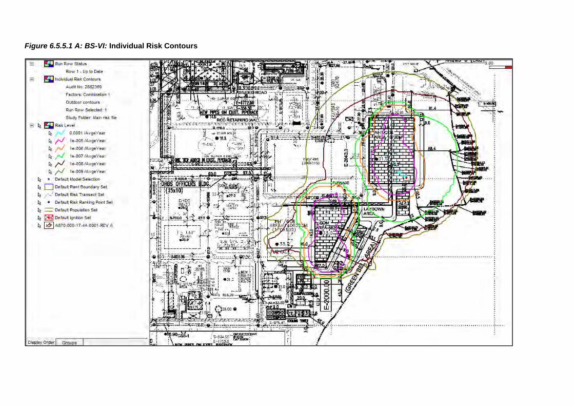
Figure 6.5.5.1 A: BS-VI: Individual Risk Contours