run - dramm wire for the common wire to help keep organized. “common” wires may be bundled or...
TRANSCRIPT

Expandable Controller3, 7, 11, 15 stations
Installation and Programming Guide
January 25, 2006
Dramm CorporationPO Box 1960 o 2000 N. 18th St
Manitowoc, WI U.S.A.920.684.0227
www.dramm.com
124
seconds. This blinking cycle is to go onuntil the low battery condition iscorrected. At that time the normaldisplay returns. Also, while “LO BA” isblinking, if the dial is turned or anybutton is pressed, the blinking normaldisplay is to appear for the next 30seconds, and then followed by theblinking cycle of “LO BA” and normaldisplay, until battery is replaced.
If there is no AC power, but sufficientpower in the battery to blink “LO BA,”then this will be displayed.
If there is no AC power and no batterypower, the display will be blank and theend user will have to reset the real timeclock and date when the power returns.
If there is no battery installed or thebattery is totally dead, the display willblink “LO BA.”
The Rain Pro controller will operatenormally if there is AC power, althoughno battery is installed or the battery istotally dead.
The battery wi ll last 2 weeks with nopower under normal conditions. It isrecommended the battery be replacedtwice a year.
NOTE:
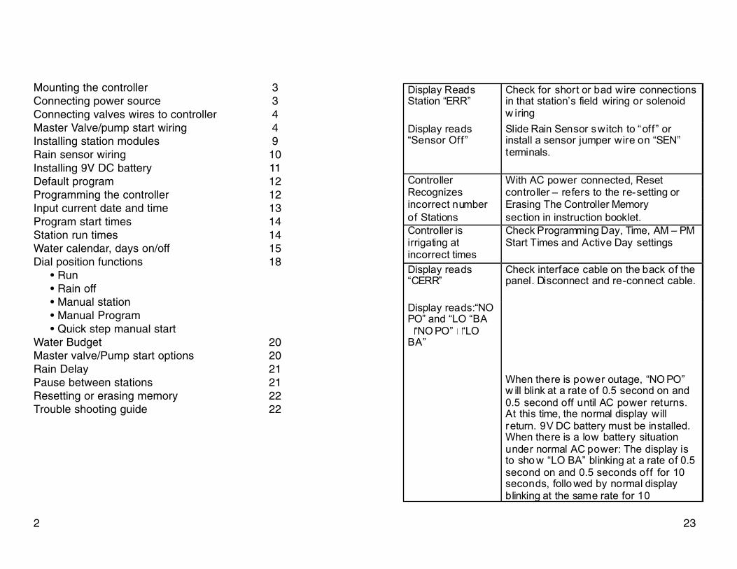
Mounting the controller 3Connecting power source 3Connecting valves wires to controller 4Master Valve/pump start wiring 4Installing station modules 9Rain sensor wiring 10Installing 9V DC battery 11Default program 12Programming the controller 12Input current date and time 13Program start times 14Station run times 14Water calendar, days on/off 15Dial position functions 18
• Run • Rain off • Manual station • Manual Program • Quick step manual start
Water Budget 20Master valve/Pump start options 20Rain Delay 21Pause between stations 21Resetting or erasing memory 22Trouble shooting guide 22
Display ReadsStation “ERR”
Check for short or bad wire connectionsin that station’s field wiring or solenoidw iring
Display reads“Sensor Off”
Slide Rain Sensor switch to “off” orinstall a sensor jumper wire on “SEN”terminals.
Controller With AC power connected, ResetRecognizes controller – refers to the re-setting orincorrect number Erasing The Controller Memoryof Stations section in instruction booklet.Controller isirrigating atincorrect times
Check Programming Day, Time, AM – PMStart Times and Active Day settings
Display reads“CERR”
Check interface cable on the back of thepanel. Disconnect and re-connect cable.
Display reads:“NOPO” and “LO “BA
“NO PO” “LOBA”
When there is power outage, “NO PO”w ill blink at a rate of 0.5 second on and0.5 second off until AC power returns.At this time, the normal display willreturn. 9V DC battery must be installed.When there is a low battery situationunder normal AC power: The display isto sho w “LO BA” blinking at a rate of 0.5second on and 0.5 seconds off for 10seconds, follo wed by normal displayblinking at the same rate for 10
232

RE-SETTING OR ERASING CONTROLLER MEMORYTo reset the clock and calendar, push the “RESET” button locatedin the recessed hole on the panel back. This will reset the clock to12:00 a.m. and the calendar to 1/1/2006. Program information willnot be affected.
To erase all programming information, turn the dial to the “CUR-RENT DATE/TIME” position, then press the minus (–) the rightarrow (¦) and PRG buttons at the same time. This will clear alluser information.
CAUTION: This appliance is not intended for use by young chil-dren or infirm persons without supervision. Young children should be supervised to ensure that they do notplay with the appliance.
TROUBLE SHOOTING GUIDE
MOUNTING THE RAIN PRO CONTROLLER
Outdoor
1. Select desired location that is at least 15 feet away froma pump, pump start relay or any high voltage junction boxesor electric motors.
2. Choose desired location and install one screw for topkeyhole into wall. Use screw anchors if attaching to drywallor masonry
3. Hang controller on this screw. Mark wall for two remain-ing screw holes and install screws accordingly to securecontroller to wall. Use screws anchors if attaching to drywallor masonry. Do not over tighten.
Note: The controller should be hard wired to the transformerby a qualified electrical technician. Use approved GFIdevice and use proper grounding techniques utilizing thegreen wire lead from the transformer. Install as per all localcodes. This will help assure safety as well as performanceand reliability of the controller.
CONNECTING POWER SOURCE
1. Leave electrical power unattached until all valve wiresand modules are installed in the controller.
322
PROBLEM CAUSE/CORRECTIONNo DisplayInformation
Check AC Po wer Supply, po wer aftertrans former should be 24-26 VACCheck AC Wiring Check Fuse or circuitbreaker Check 9V DC battery
Display reads“ERR”
Master Module not installed properlyTurn off AC Power & Restart after 30seconds See Remote Control WiringInstructions
Display Reads “PERR”
Check for “short” or bad wireconnections in the pump start or MasterValve wiring or solenoid wiring

2. When attaching power, transformer must be connect-ed utilizing wire nuts and/or other locally approved connec-tions per code. 3. A switching means should be provided in the supply conductors with an air gap separation in each pole Note:Some models are fitted with a power lead. This may beused when connecting to a standard electrical outlet.
CONNECTING VALVE WIRES TO THE CONTROLLER
1. Connect wire from each valve to the desired correspon-ding number on the terminal. Route all valve wires throughthe large hole in the bottom right of the controller. 2. Connect the remaining valve wire from all valves to the“com” or common terminal. It is suggested to use a differentcolor wire for the common wire to help keep organized.“Common” wires may be bundled or wired together with allother common wires from the valves to the “Com” terminalof the controller. 3. Wire sizing should be of a significant size to allow a maxi-mum of 5 volts drop between the controller and the valves.Use Ohm's Law to calculate wire voltage drop. Higher oper-ating pressures require higher voltage (less voltage loss) atthe valve. Note: All in-field wire splices should be made usingwaterproof, gel-filled Dramm RPDBC-Y type connectorsor equivalent.
MASTER VALVE/PUMP START WIRING If a master valveor pump start relay is being used in conjunction with thiscontroller, wire as follows.
3. Push the ¦ button to select the station. 4. Rotate dial to the “RUN” position. NOTE: Pump Start/Master Valve circuit does not operateduring “PAUSE”.
RAIN DELAY1. Rotate the dial to the “RAIN/OFF” position. 2. Use the + button to select a number 1 - 7 “Days Left.” 3. Rotate the dial back to “RUN” 4. The display will read “OFF” and the number of “DAYSLEFT5. The controller will not run until the numbers of days havepast. The days will change at midnight.
PROGRAMMABLE PAUSE BETWEEN STATIONS 1. Rotate dial to “RUN” position.
2. While depressing the – button, simultaneously rotate dialto “Station Run Times” position.
3. Leave dial in this position, remove finger from the – button. Delay time will be flashing.
4. Push the + or – buttons to select the desired delay timebetween each station operation. Range of programmabledelay is 1 second to 4:00 (four hours and zero minutes).
5. Rotate dial back to the “RUN” position to enter this newdata in controller. NOTE: Pump Start/Master Valve circuit will not operateduring “PAUSE”.
214

4. Push the ¦ button to desired station to commence cycle.Station will start in 2 seconds and then sequence through allremaining stations. 5. This will allow for a “Quick Review” of programmedstation run times by program and/or a “Quick Review” ofsystem for inspection/performance purposes.
WATER BUDGET The water budget feature provides a one step universal sta-tion run time adjustment in 10% increments up or down. Itaffects all station run times in all programs. In hotter, drierweather, you can increase the water budget in 10% incre-ments to 150% of originally programmed station run times.In periods of cooler/wetter weather, you can water budgetdownward in 10% increments to as low as 10% of originally programmed station run times.
1. With dial in any position, press up arrow to increase waterbudget or down arrow to decrease water budget. 2. The actual individual station run times as affected by thecurrent water budget setting can be viewed by rotating thedial to “Station Run Times.” 3. To check the current water budget level setting or to getthe 100% (original setting/base setting), rotate the dial to the“RUN” position. Press either the up or down arrow. The cur-rent setting will be displayed.
BONUS FEATURES Activate or De-activate Master Valve/Pump Start by Station: 1. Rotate dial to Pump/Master Valve ON/OFF. “ON” will behighlighted. 2. Push the – button to change from ON to OFF.
1 Remove junction box cover to gain access to transformerwires.
2 Turn off Power before making connections. 3 Replace cover
It is recommended that a licensedElectrician perform the followingpower installations.
520
POWER CONNECTION FOR DRAMMINTERNAL TRANSFORMER
Power In 220 VACPower In 110 VAC

CONNECTING A PUMP START RELAY
1 Make a connection from the “Com” Terminal on theMaster Module to one of the wires on the 24 VAC PumpStart Relay coil. (Black lead on DRAMM Pump Start Relay )
2 Make connection from the “P/MV” Terminal on the MasterModule to the other coil wire on the 24 VAC Pump StartRelay.
(Remaining Black lead on DRAMM Pump Start Relay)
MANUAL PROGRAM To manually activate one completecycle of either program A, B or C.
1. Rotate dial to “Manual Program.” 2. Choose program A, B or C. To change program fromexisting program, push the PRG button. 3. Push the ¦ button to choose the first station in thesequence of the manual program to start. 4. The “run time” for each station will be displayed as cur-rently programmed. For this cycle only, you can customizeeach station run time without affecting the individually pro-grammed station run times within a program. 5. Push the ¦ button to sequence through all the stations,using the + or – buttons to select the desired run times forthis cycle only. 6. Push the ¦button until the station number appears ofwhich you want to start this custom cycle. 7. Rotate dial to “RUN” to start this custom, one¬time cycle.It will start with station number displayed in Step 6. 8. Once completed, controller will revert to programmed“automatic” operation.
“QUICK STEP” MANUAL START/ADVANCE OR REVIEWWITHOUT USING THE DIAL
1. Push the ¦ button continuously for 2 seconds. 2. Program “A” values will be displayed. 3. Push the ¦ or ¥to view the different stations and theirprogrammed run times. Individual station run times may beadjusted using the + or – buttons.
196
DRAMM RPPS Series

4. Push the ¦ button again and the days of the week “Mon”will flash. 5. Press the ¦button until the day you desire as a “NoWater Day” is flashing. 6. Press the – button to designate this day as a “No WaterDay.” This specific day will now be circled. 7. Repeat steps 6 and 7 for all desired “No Water Days” ona weekly calendar. 8. Rotate dial to “RUN” to enter data in controller. DIAL POSITIONS AND FUNCTIONS RUN - Rotate the dialto the “RUN” position after completing any programming toenter this new data in controller. Leave the dial in the RUNposition to have the controller operate as programmed.RAIN/OFF - Rotate the dial to the “RAIN/OFF” position tostop all output of the controller. All irrigation will stop. Toreturn to normal operation, rotate dial back to “RUN.” MAN-UAL STATION - To manually activate a single station oncefor a programmed length of time.
1.Rotate dial to “Manual Station.”
2. Push ¦ to desired station number.
3. Push + or – buttons to input length of time this station willnow operate this one time.
4. Rotate dial to “RUN” position.
5. Upon completion of this station operating manually for length of time input, the controller will revert back to“RUN” and operate as previously programmed.
VALVE CONNECTION
PRO Series Solenoid Valve
1 For each valve, make a connection from one of the sole-noid wires to the “Com” Terminal on the Master Module.
2 For each valve, make a connection from the numberedstation terminals of the modules to the other solenoid wire.
Note : Step 2 determines the valve numbered for the programming of Controller.
718

MASTER VALVE CONNECTION
1 Make one connection from the “Com” Terminal on theMaster Module to one of the Master Valve Solenoid wires.
2 Make one connection from the “P/MV” Terminal on theMaster Module to the other Master Valve Solenoid wire.
Left” will not exceed the “Interval” schedule selected.4. Rotate dial to “Run” to enter this data in controller.
UTILIZING “ODD OR EVEN” DAY SCHEDULING “Odd” or“Even” day scheduling is typically used to comply with regu-latory watering rules. ODD/EVEN scheduling allows you toirrigate on only “ODD” numbered or “EVEN” numbered daysof the month. 1. Follow the “Interval Day” watering schedule instructionsabove utilizing steps 1 and 2 and set the “Interval Day” to 1. 2. Push the ¦ button to highlight option not desired ODD orEVEN. 3. Push the ¦ button to eliminate either the ODD or EVENschedule as a “No Water Days.” A circle will appear abovethe eliminated choice. If EVEN is selected as “No WaterDays” only ODD numbered days will irrigate. Select ODD asa “No Water Days” and only Even numbered days will irri-gate. NOTE: If ODD days are active days, February 29 and the31st of any month will not irrigate. 4. Rotate dial to “Run” to enter data in controller.
UTILIZING THE “NO WATER DAY” OPTION (Only foroverriding the ODD/EVEN or Interval Schedule for a specificday or days of the week when you regularly desire no irriga-tion to take place for maintenance or other reasons.) 1. Rotate dial to Calendar/Schedule 2. Press the ¦ button until the cursor is on “Sunday.” Thiswill change the program to “Interval Day” schedule. 3. Press the ¦ button and the “Interval” will flash.
178
Pro SeriesMaster Valve

UTILIZING THE “SPECIFIC DAYS OF THE WEEK” TOIRRIGATE
1. Choose program A, B or C. To change program fromexisting program, push the PRG button. 2. Using the + and - buttons will make a day either active orinactive. “+” indicates an active day or non-circled. Press the“-” button to change to a circled day, which indicates aninactive day. The days of the week will automaticallyadvance. 3. Repeat step 2 for each day of the week. The ¦ buttonmay be used to advance to a particular day of the week. 4. After programming days of the week as desired, rotatedial to “RUN” to enter this new data into controller.
UTILIZING THE “INTERVAL DAY” SCHEDULE IntervalDay allows you to choose to irrigate at an interval rangingfrom every day (1), every second day (2), up to every 31stday (31). “Days left” indicates the number of days remaininguntil the next scheduled irrigation cycle will occur for thatspecific program. As an example, if 2 is the “interval” and 1is the “Days Left,” irrigation will occur tomorrow.
1. Push the ¦ button when the cursor is on Sunday. Thiswill change the program to an “Interval Day” schedule. 2. Push the + button to increment the “Interval” indicating thedesired number of days from 2 - 31 days between irrigationcycles. 3. Next, push the ¦ button and the number of “Days Left”will flash. Use the + or - buttons to choose the number ofdays until you desire this irrigation cycle to start. Number of“Days
1. Route two wires from the master valve or pump start relayup through the bottom right side large hole. Connect onewire to the “P/MV” terminal and one to the “Com” terminal. 2. if using a pump relay, it must be;
• Located at least 15 feet from the controller. • Have a maximum rated inrush current less than 350MA
at 24VAC. • Properly sized for your application Dramm offers a wide
range of pump start relays for most applications that arecompatible with the Rain Pro controller. Note: DO NOT connect controller directly to pump.Controller will be damaged if controller is connected directlyto a pump.
INSTALLING STATION MODULES The Rain Pro controller is shipped from the factory with one3 station module installed. This is supplied for valves #1, #2and #3. Additional modules can be purchased separatelyand are easily installed to increase the controller stations in4 station increments, from 3 stations, to 7 stations, to 11 sta-tions and to a maximum of 15 stations.
1. Insert additional module(s) in the terminal strip area of thecontroller as needed. Slide each module from right to left.Firmly slide module in until it clicks into place. Each modulewill add 4 stations of additional capacity to the controller.Install modules in sequence from bottom to top leaving nogaps.
916

CONNECTING A WEATHER SENSOR
1. Make a connection with one wire of the Rain Sensor tothe Terminal marked “SEN”.
2 . Make a connection with the other wire of the RainSensor to the other Terminal marked “SEN”.
2. Choose program A, B, or C. To change program fromexisting program, push the “PGM” button. 3. Press the + or - button to increase or decrease thelength of time you desire for this specific station (valve) tobe “ON” each time this valve is activated on this specificprogram. 4. Press the ¦button to go to the next station. 5. Repeat steps 3 and 4 for each station that is to be activeon each specific program. For stations/valves that are inac-tive on a specific program, put “Station Run Times at “0:00”. 6. Each individual “Station Run Times” can range from 1minute to 6 hours in duration. 7. Rotate dial to “RUN” to enter new data into the controller. Note: Water Budget should be set at 100% whenprogramming station/valve “Run Times”.
SETTING WATERING SCHEDULE/CALENDAR OF “ON” DAYS
1. Rotate the dial to “Calendar/Schedule.”
2. Choose program A, B or C. To change program fromexisting program, push the PRG button.
3. The controller has 4 active day schedule options: specificdays of the week, interval watering (every 2nd, 3rd, 4thday), ODD or EVEN days of the month. Only one of theseschedule options is available simultaneously for each inde-pendent program. Each independent program can utilize dif-ferent/same schedule option.
1510
Remove Jumper whenUsing Rain Sensor
Dramm RPRSSensor
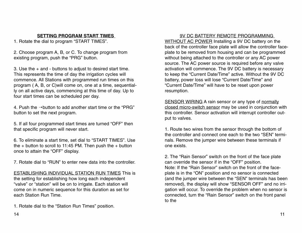
SETTING PROGRAM START TIMES 1. Rotate the dial to program “START TIMES”.
2. Choose program A, B, or C. To change program fromexisting program, push the “PRG” button.
3. Use the + and - buttons to adjust to desired start time.This represents the time of day the irrigation cycles willcommence. All Stations with programmed run times on thisprogram ( A, B, or C)will come on, one at a time, sequential-ly on all active days, commencing at this time of day. Up tofour start times can be scheduled per day.
4. Push the ¦button to add another start time or the “PRG”button to set the next program.
5. If all four programmed start times are turned “OFF” thenthat specific program will never start.
6. To eliminate a start time, set dial to “START TIMES”. Usethe + button to scroll to 11:45 PM. Then push the + buttononce to attain the “OFF” display.
7. Rotate dial to “RUN” to enter new data into the controller.
ESTABLISHING INDIVIDUAL STATION RUN TIMES This isthe setting for establishing how long each independent“valve” or “station” will be on to irrigate. Each station willcome on in numeric sequence for this duration as set foreach Station Run Time.
1. Rotate dial to the “Station Run Times” position.
9V DC BATTERY REMOTE PROGRAMMING WITHOUT AC POWER Installing a 9V DC battery on theback of the controller face plate will allow the controller face-plate to be removed from housing and can be programmedwithout being attached to the controller or any AC powersource. The AC power source is required before any valveactivation will commence. The 9V DC battery is necessaryto keep the “Current Date/Time” active. Without the 9V DCbattery, power loss will lose “Current Date/Time” and“Current Date/Time” will have to be reset upon powerresumption.
SENSOR WIRING A rain sensor or any type of normallyclosed micro-switch sensor may be used in conjunction withthis controller. Sensor activation will interrupt controller out-put to valves.
1. Route two wires from the sensor through the bottom ofthe controller and connect one each to the two “SEN” termi-nals. Remove the jumper wire between these terminals ifone exists.
2. The “Rain Sensor” switch on the front of the face platecan override the sensor if in the “OFF” position. Note: If the “Rain Sensor” switch on the front of the face-plate is in the “ON” position and no sensor is connected(and the jumper wire between the “SEN” terminals has beenremoved), the display will show “SENSOR OFF” and no irri-gation will occur. To override the problem when no sensor isconnected, turn the “Rain Sensor” switch on the front panelto the
1114

“OFF” position. If no “Rain Sensor” is attached to the con-troller always leave the switch in “OFF” position.
DEFAULT PROGRAM The controller has no default programafter a power outage. The controller has a non-volatilememory and will retain your custom program.
Note: If no battery is installed or a low battery conditionexists and AC power is lost, the “CURRENT DATE/TIME”will be lost. When AC power is restored the “CURRENTDATE/TIME” will default to 12:00 AM and 1/1/06. It isimportant to check or change the 9V DC battery to pre-vent losing the “CURRENT DATE/TIME”.
PROGRAMMING THE CONTROLLER To successfully program the controller, all three programmingelements must be completed. They are: Program start times(Time of day a complete programmed cycle will start. StationRun Times (The length of time each station/valve will operate)Calendar/Schedule (The days of the week/calendar that youdesire to irrigate.) To program the controller, you are provided+ or - buttons that will change the value of the “flashing dis-play”. The ¥ or ¦ buttons change the subject of informationthat is flashing. The subject or “flashing display” is insequence and can be scrolled forward ¦ or ¥backwards toaccess all desired programming options.
BASIC PROGRAMMING FEATURES
1. Three independent programs are available A, B and C. 2. Four program start times per program are available. 3. Calendar/schedule, days of the week, ODD/EVEN or indi-vidual interval scheduling options. 4. Individual station runtimes.
INPUT THE CURRENT DATE AND TIME
1. Turn the dial to the CURRENT DATE/TIME
2. Use the + and - buttons to select the current year. Pushthe ¦ button to activate the month.
3. The month will be flashing. Use the + and - buttons toselect the current month. Press the ¦ button to set the day.
4. The day will be flashing. Use the + and - buttons to selectthe current date. Push the ¦ button to set current time.
5. The time will be displayed. Use the + and - buttons toselect the current AM, PM or 24 hr notation. Press the ¦button to go to hours. Hours will be flashing. Use the + and -buttons to set the current hour. Push the ¦ button to setminutes. Use the + and - buttons to select current time inminutes.
6. Rotate dial to “RUN” to enter new data into the controller.
1312