s. kahn 5 june 2003nufact03 tetra cooling ringpage 1 tetra cooling ring steve kahn for v. balbekov,...
TRANSCRIPT
S. Kahn 5 June 2003 NuFact03 Tetra Cooling Ring Page 1
Tetra Cooling Ring
Steve KahnFor
V. Balbekov, R. Fernow, S. Kahn, R. Raja, Z. Usubov
S. Kahn 5 June 2003 NuFact03 Tetra Cooling Ring Page 2
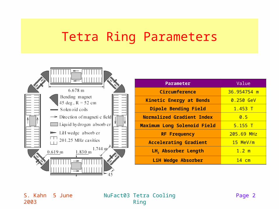
Tetra Ring Parameters
Parameter Value
Circumference 36.954754 m
Kinetic Energy at Bends 0.250 GeV
Dipole Bending Field 1.453 T
Normalized Gradient Index 0.5
Maximum Long Solenoid Field 5.155 T
RF Frequency 205.69 MHz
Accelerating Gradient 15 MeV/m
LH2 Absorber Length 1.2 m
LiH Wedge Absorber 14 cm
S. Kahn 5 June 2003 NuFact03 Tetra Cooling Ring Page 3
Tetra Ring Simulations
• Original concept for this ring comes from V. Balbekov.– Originally simulated in Valeri’s program.– Documented:
• V. Balbekov et al., Muon Ring Cooler for the Mucool Experiment, Proc PAC 2001 Conf., p. 3867.
• Updated in MUCnote 249 (2002).
• GEANT simulation of Tetra Ring.– Worked on by Z. Usubov, R. Raja, and myself.
• ICOOL simulation of the Balbekov Ring.– MUCnote 258.
S. Kahn 5 June 2003 NuFact03 Tetra Cooling Ring Page 4
Hardedge Model
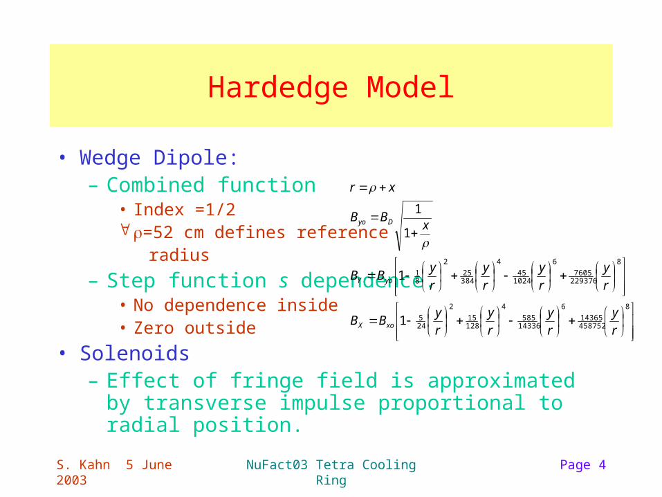
• Wedge Dipole:– Combined function
• Index =1/2 =52 cm defines reference radius
– Step function s dependence.• No dependence inside• Zero outside
• Solenoids– Effect of fringe field is approximated by transverse
impulse proportional to radial position.
8
45875214365
6
14336585
4
12815
2
245
8
2293767605
6
102445
4
38425
2
81
1
1
1
1
r
y
r
y
r
y
r
yBB
r
y
r
y
r
y
r
yBB
xBB
xr
xoX
yoY
Dyo
S. Kahn 5 June 2003 NuFact03 Tetra Cooling Ring Page 5
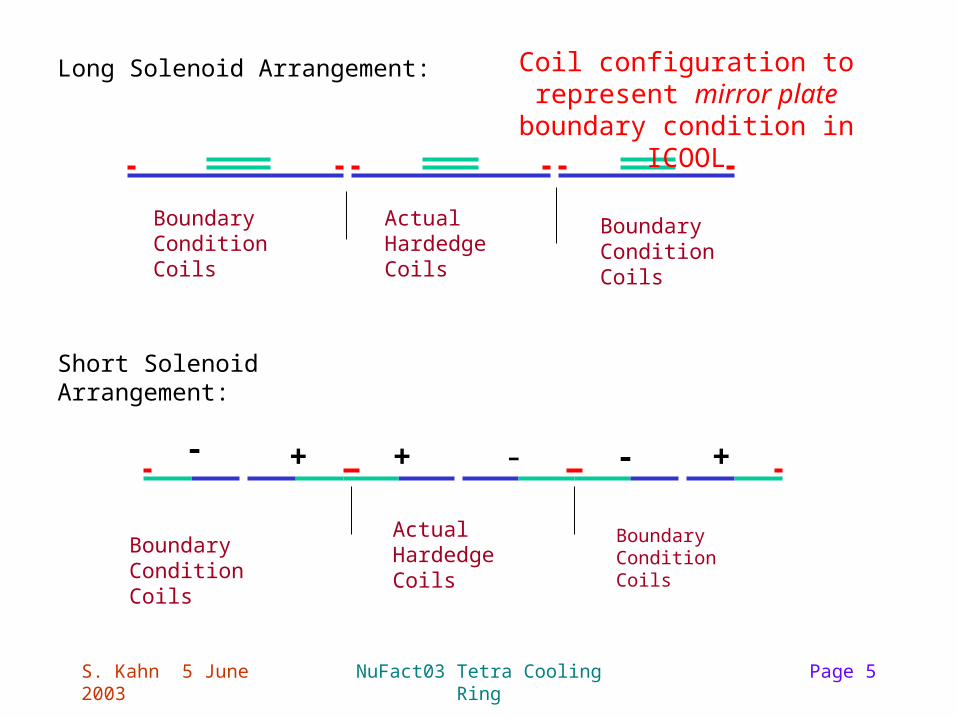
Long Solenoid Arrangement:
Boundary Condition Coils
Actual Hardedge Coils
Boundary Condition Coils
Short Solenoid Arrangement:
Actual Hardedge Coils
Boundary Condition Coils
Boundary Condition Coils
+ - - ++-
Coil configuration to represent mirror plate boundary condition in ICOOL
S. Kahn 5 June 2003 NuFact03 Tetra Cooling Ring Page 6
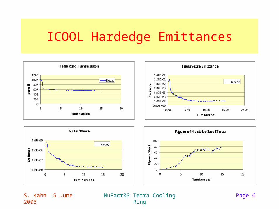
ICOOL Hardedge Emittances
Tetra Ring Transmission
0
200
400
600
800
1000
1200
0 5 10 15 20
Turn Number
per
mil
Decay
Transverse Emittance
0.00E+00
2.00E-03
4.00E-03
6.00E-03
8.00E-03
1.00E-02
1.20E-02
1.40E-02
0.00 5.00 10.00 15.00 20.00
Turn Number
Em
itta
nce
Decay
6D Emittance
1.0E-08
1.0E-07
1.0E-06
1.0E-05
0 5 10 15 20
Turn Number
Em
itta
nce
decay
Figure of Merit for Icool Tetra
0
20
40
60
80
100
0 5 10 15 20
Turn Number
Fig
ure
of
Me
rit
S. Kahn 5 June 2003 NuFact03 Tetra Cooling Ring Page 7
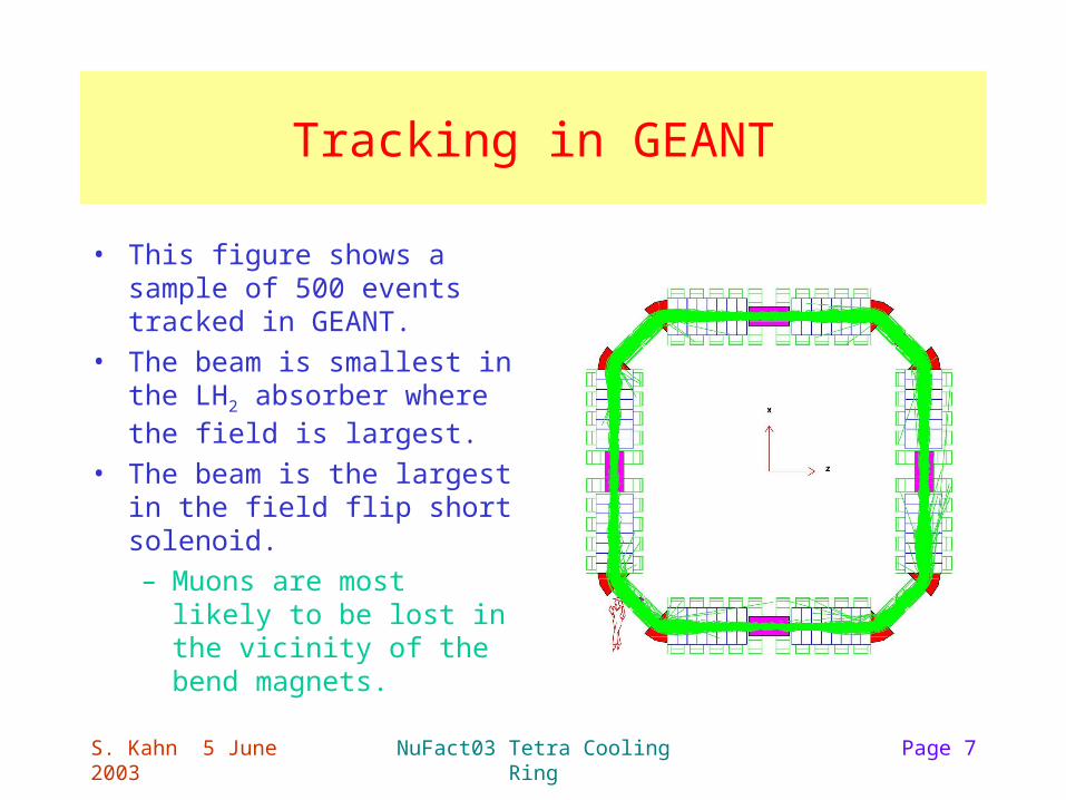
Tracking in GEANT
• This figure shows a sample of 500 events tracked in GEANT.
• The beam is smallest in the LH2 absorber where the field is largest.
• The beam is the largest in the field flip short solenoid.
– Muons are most likely to be lost in the vicinity of the bend magnets.
S. Kahn 5 June 2003 NuFact03 Tetra Cooling Ring Page 8
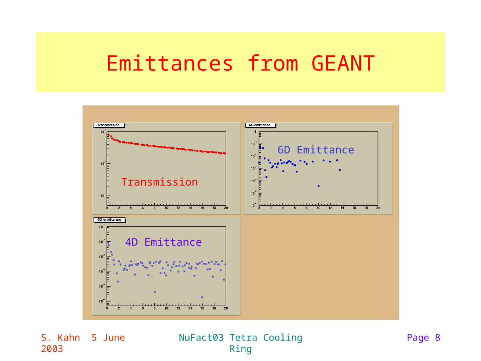
Emittances from GEANT
Transmission
4D Emittance
6D Emittance
S. Kahn 5 June 2003 NuFact03 Tetra Cooling Ring Page 9
Toward a Realistic Muon Cooling Ring
• The hardedge field description of this cooling ring violates Maxwell’s equations.
– It is likely that smoothing out a step function to a tanh or Enge function would solve this, but this has to be demonstrated.
• There is no free space in the lattice.
– This space would be necessary for flux returns for the solenoids and field clamps for the dipole magnet.
• Flux returns and field clamps are necessary to separate the function of the different lattice elements.
• Difficult engineering issues like how to inject (eject) beam into (out of) this ring.
– These kind of issues will be ignored at this point.
S. Kahn 5 June 2003 NuFact03 Tetra Cooling Ring Page 10
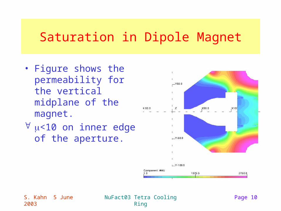
Saturation in Dipole Magnet
• Figure shows the permeability for the vertical midplane of the magnet.
<10 on inner edge of the aperture.
S. Kahn 5 June 2003 NuFact03 Tetra Cooling Ring Page 11
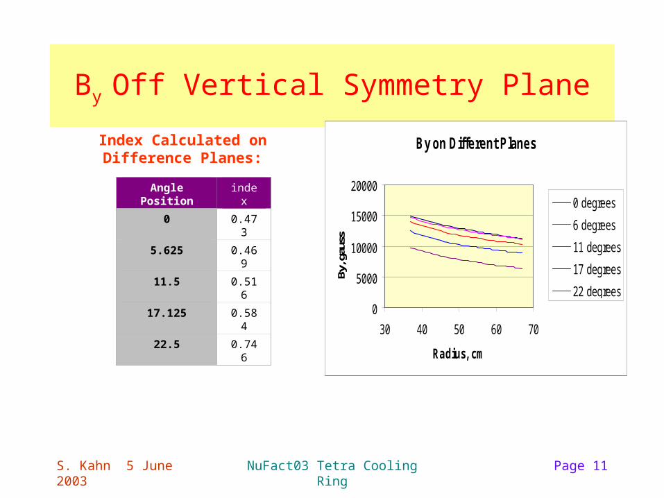
By Off Vertical Symmetry Plane
By on Different Planes
0
5000
10000
15000
20000
30 40 50 60 70
Radius, cmBy
, gau
ss
0 degrees
6 degrees
11 degrees
17 degrees
22 degrees
Angle Position index
0 0.473
5.625 0.469
11.5 0.516
17.125 0.584
22.5 0.746
Index Calculated on Difference Planes:
S. Kahn 5 June 2003 NuFact03 Tetra Cooling Ring Page 12
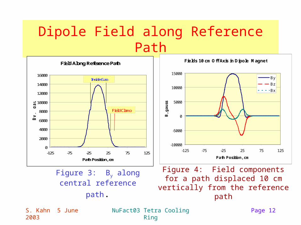
Dipole Field along Reference Path
Field Along Reference Path
0
2000
4000
6000
8000
10000
12000
14000
16000
-125 -75 -25 25 75 125
Path Position, cm
By,
gau
ss
Inside Gap
Field Clamp
Figure 4: Field components for a path displaced 10 cm vertically from the
reference path
Fields 10 cm Off Axis in Dipole Magnet
-10000
-5000
0
5000
10000
15000
-125 -75 -25 25 75 125
Path Position, cm
B,
ga
uss
By
Bz
Bx
Figure 3: By along central
reference path.
S. Kahn 5 June 2003 NuFact03 Tetra Cooling Ring Page 13
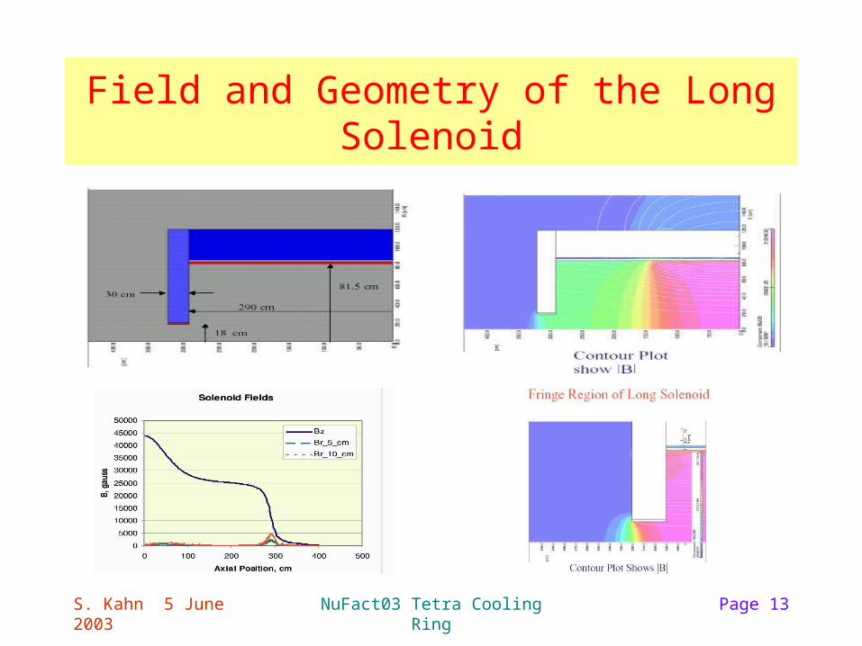
Field and Geometry of the Long Solenoid
S. Kahn 5 June 2003 NuFact03 Tetra Cooling Ring Page 14
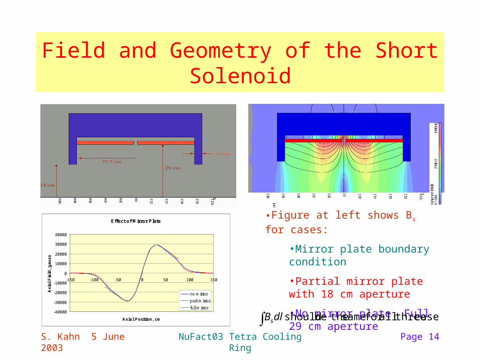
Field and Geometry of the Short Solenoid
Effect of Mirror Plate
-40000
-30000
-20000
-10000
0
10000
20000
30000
40000
-150 -100 -50 0 50 100 150
Axial Position, cm
Axi
al F
ield
, g
auss
no mirror
part mirror
full mirror
•Figure at left shows Bs for cases:
•Mirror plate boundary condition
•Partial mirror plate with 18 cm aperture
•No mirror plate. Full 29 cm aperture
cases threeallfor same thebe should dlBs
S. Kahn 5 June 2003 NuFact03 Tetra Cooling Ring Page 15
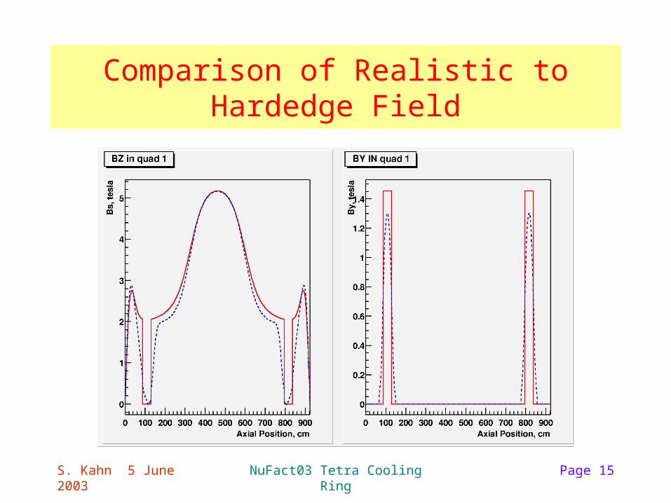
Comparison of Realistic to Hardedge Field
S. Kahn 5 June 2003 NuFact03 Tetra Cooling Ring Page 16
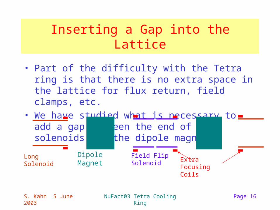
Inserting a Gap into the Lattice
• Part of the difficulty with the Tetra ring is that there is no extra space in the lattice for flux return, field clamps, etc.
• We have studied what is necessary to add a gap between the end of the solenoids and the dipole magnet:
Dipole MagnetLong Solenoid Field Flip SolenoidExtra Focusing Coils
S. Kahn 5 June 2003 NuFact03 Tetra Cooling Ring Page 17
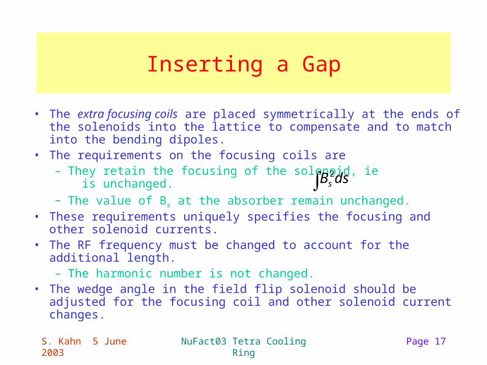
Inserting a Gap
• The extra focusing coils are placed symmetrically at the ends of the solenoids into the lattice to compensate and to match into the bending dipoles.
• The requirements on the focusing coils are– They retain the focusing of the solenoid, ie is unchanged.– The value of Bs at the absorber remain unchanged.
• These requirements uniquely specifies the focusing and other solenoid currents.
• The RF frequency must be changed to account for the additional length.– The harmonic number is not changed.
• The wedge angle in the field flip solenoid should be adjusted for the focusing coil and other solenoid current changes.
dsBs 2
S. Kahn 5 June 2003 NuFact03 Tetra Cooling Ring Page 18
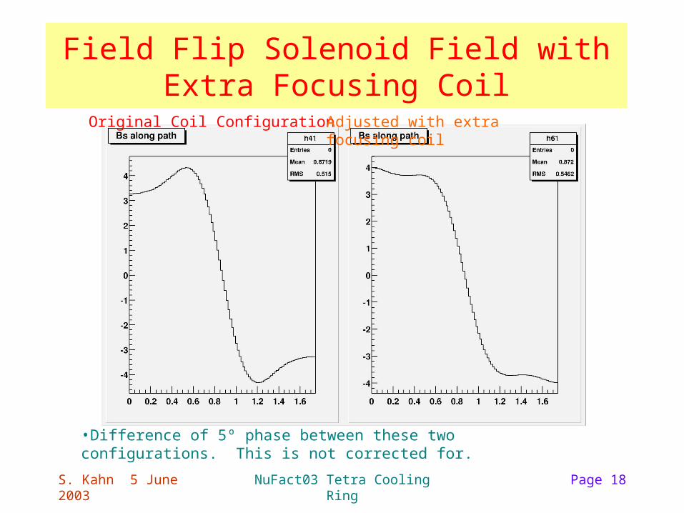
Field Flip Solenoid Field with Extra Focusing Coil
Original Coil Configuration Adjusted with extra focusing coil
•Difference of 5º phase between these two configurations. This is not corrected for.
S. Kahn 5 June 2003 NuFact03 Tetra Cooling Ring Page 19
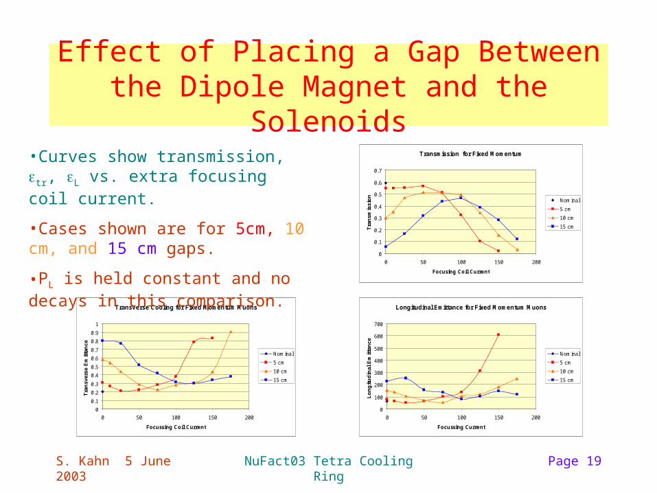
Effect of Placing a Gap Between the Dipole Magnet and the Solenoids
Transmission for Fixed Momentum
0
0.1
0.2
0.3
0.4
0.5
0.6
0.7
0 50 100 150 200
Focusing Coil Current
Tra
nsm
issi
on
Nominal
5 cm
10 cm
15 cm
Transverse Cooling for Fixed Momentum Muons
0
0.1
0.2
0.3
0.4
0.5
0.6
0.7
0.8
0.9
1
0 50 100 150 200
Focussing Coil Current
Tra
nsv
erse
Em
itta
nce
Nominal
5 cm
10 cm
15 cm
Longitudinal Emittance for Fixed Momentum Muons
0
100
200
300
400
500
600
700
0 50 100 150 200
Focussing Current
Lo
ng
itu
din
al E
mit
tan
ce
Nominal
5 cm
10 cm
15 cm
•Curves show transmission, tr, L vs. extra focusing coil current.
•Cases shown are for 5cm, 10 cm, and 15 cm gaps.
•PL is held constant and no decays in this comparison.
S. Kahn 5 June 2003 NuFact03 Tetra Cooling Ring Page 20
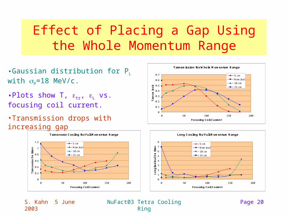
Effect of Placing a Gap Using the Whole Momentum Range
Transmission for Whole Momentum Range
0
0.1
0.2
0.3
0.4
0.5
0.6
0.7
0 50 100 150 200
Focusing Coil Current
Tra
ns
mis
sio
n
5 cm
Nominal
10 cm
15 cm
Transverse Cooling for Full Momentum Range
0
0.2
0.4
0.6
0.8
1
1.2
0 50 100 150 200
Focusing Coil Current
Tra
ns
ve
rse
Em
itta
nc
e
5 cm
Nominal
10 cm
15 cm
Long Cooling for Full Momentum Range
0
1
2
3
4
5
6
7
8
0 50 100 150 200
Focusing Coil Current
Lo
ng
itu
din
al
Em
itta
nc
e 5 cm
Nominal
10 cm
15 cm
•Gaussian distribution for PL with P=18 MeV/c.
•Plots show T, tr, L vs. focusing coil current.
•Transmission drops with increasing gap
S. Kahn 5 June 2003 NuFact03 Tetra Cooling Ring Page 21
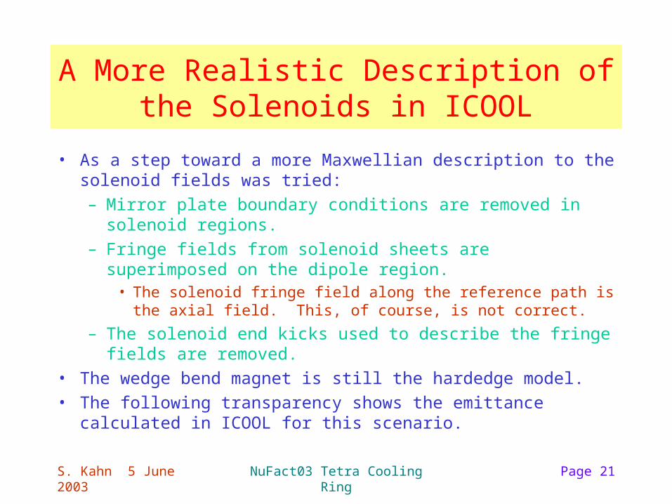
A More Realistic Description of the Solenoids in ICOOL
• As a step toward a more Maxwellian description to the solenoid fields was tried:
– Mirror plate boundary conditions are removed in solenoid regions.
– Fringe fields from solenoid sheets are superimposed on the dipole region.
• The solenoid fringe field along the reference path is the axial field. This, of course, is not correct.
– The solenoid end kicks used to describe the fringe fields are removed.
• The wedge bend magnet is still the hardedge model.
• The following transparency shows the emittance calculated in ICOOL for this scenario.
S. Kahn 5 June 2003 NuFact03 Tetra Cooling Ring Page 22
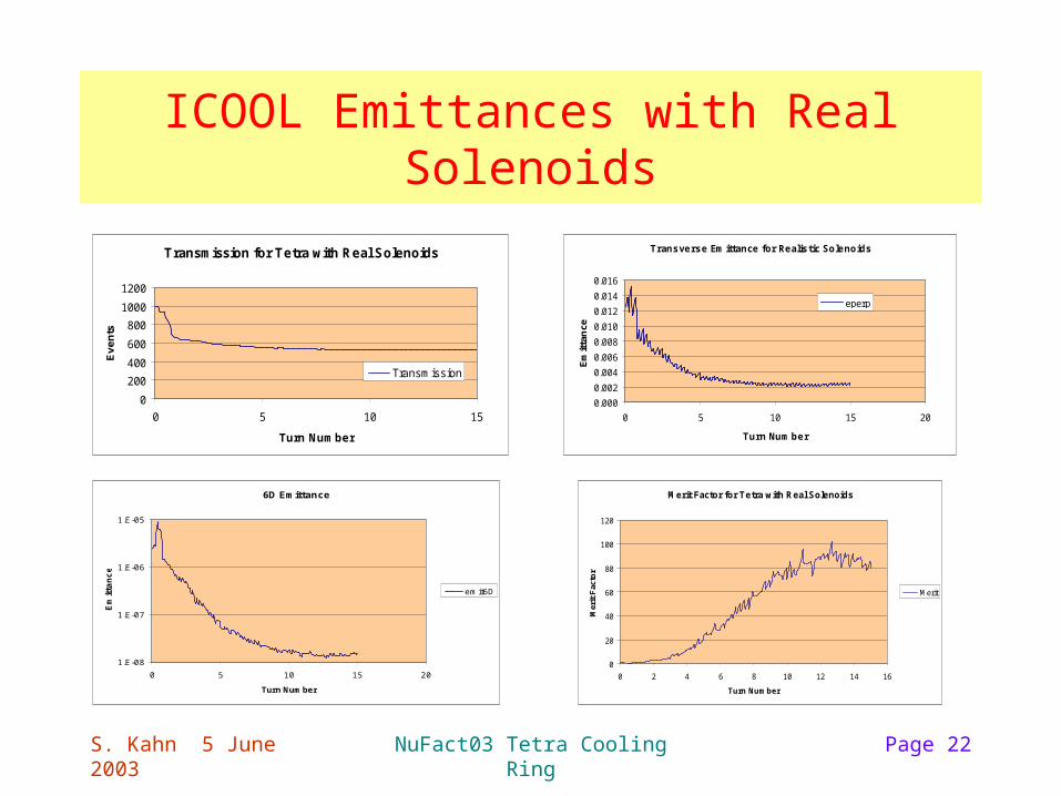
ICOOL Emittances with Real Solenoids
Transmission for Tetra with Real Solenoids
0
200
400
600
800
1000
1200
0 5 10 15
Turn Number
Ev
en
ts
Transmission
Transverse Em ittance for Realis tic Solenoids
0.000
0.002
0.004
0.006
0.008
0.010
0.012
0.014
0.016
0 5 10 15 20
Turn Num ber
Em
itta
nce
eperp
Merit Factor for Tetra with Real Solenoids
0
20
40
60
80
100
120
0 2 4 6 8 10 12 14 16
Turn Number
Mer
it F
acto
rMerit
6D Emittance
1.E-08
1.E-07
1.E-06
1.E-05
0 5 10 15 20
Turn Number
Em
itta
nc
e
em it6D