safe lithium-ion battery designs for use, … lithium-ion battery designs for use, transportation...
TRANSCRIPT

UL and the UL logo are trademarks of UL LLC © 2015
Safe Lithium-ion Battery
Designs for Use,
Transportation and Second Use
Judy Jeevarajan, Ph.D.
Underwriters Laboratories Inc.
March 2016
Battery Safety Symposium
International Battery Seminar 2016
Ft. Lauderdale, FL

Introduction• Lithium ion batteries are being used in ground, aviation, space, sea, etc. applications in
various sizes
• Introduced in recent years into the utility/stationary energy storage industry
• Energy Storage Industry deployed 40.7 MW of capacity in Q2 2015 (9 times compared
to Q2 2014)
• Other cumulative installations totalled 5.6 MW
• Total ~ 50 MW in 2015
• Goal: Build or Purchase 1.3 GW of storage by 2020 in California
• Automotive batteries are being repurposed for utility/stationary storage applications
• With increasing energy density at the cell level and with the need for high voltage, high
capacity, high power battery systems, questions arise on the safety of the battery
systems
• Has a detailed FMEA/FTA been created for the energy storage system?
• Have all the system level hazards been addressed?
• Has extensive testing been carried out at all levels to confirm that safety controls designed at
each level work as expected – cell, module, battery, etc.
• Does the safety change with other factors?
• Size of battery?
• Environments (temperature, pressure, dust, humidity, vibrations, etc.)?
• Cycle and calendar life (including storage)?
• Special transportation needs and safety during transportation?
• Other unique requirements? 2

Growth in Size of Batteries used for Various
Applications
Challenges:• Cell to Module to Battery Level Scale-UpCell level controls do not necessarily translate to module or battery
level controls
• Testing in the Relevant EnvironmentAll safety controls need to be verified by testing at the appropriate
level and in the relevant environment
Example: Hazards such as overcharge and external short have opposite outcomes in pressurized versus non-pressurized environments due to the difference in heat dissipation
3

Battery Manufacturing Process
Challenges
• Tens of thousands to billions of cells manufactured for different types
of applications from portable equipment to large ESS.
• Challenge is to screen and match every individual cell.
• Typical COTS and some custom battery manufacturing process does not
include cell screening and matching.
• Cells are assembled into batteries in the ‘as received” condition at lower
SOC (typically 40%)
• Are assembled batteries tested under relevant stringent
conditions before sent out into the field?
• Battery certification tests that are comprehensive enough with
stringent pass/fail criteria
• Certification tests that verify the operation of the safety controls
designed into the battery
4

Challenges with Large Battery Designs
5
Module 1
Module 2
Module 3
Module 6
Module 5
Module 4
BMS 1 BMS 2 BMS 3
Thermal Gradient
Deviations: Voltage,
capacity, internal
resistance/impedance
Eventually safety is ?
Example:
Forced Air Cooling Inlets at one end of Battery

Other Challenges
6
Flammability
and
Offgassing
Toxicity
Environmental
Pollution
High
Voltage
Safety
Complexity of sensing
systems / BMS
Quality of
Sensors,
electronics,
protective
devices,
software
Fire
Extinguishing
methods
Transportation Safety

Lithium-ion Batteries: Hazards
7
Internal Shorts
Manufacturing
Defects
Misuse in
the Field
Overcharge
Extreme Thermal
Environments
High/Low
temperatures/
Repeated
Overdischarge/
Overdischarge
followed by
charge
External
Shorts
High and Low
Impedance

Overcharge and Overdischarge Hazard Causes
8
Overvoltage /
High Rate
Charge
Electrolyte
Decomposition
Fire
Thermal
RunawayCathode
Destabilization
and release of
O2
Undervoltage
/ High Rate
Discharge
Dissolution
of Copper
Current
Collector
Benign
Internal
Shorts
Lack of
intercalation sites
Or

Cell Protective Devices and Limitations
9
Lithium-ion cells, whether cylindrical, prismatic, etc. irrespective of size, have different forms of
internal protective devices
• PTC
• CID
• Tab/lead meltdown
• (fusible link type)
• Bimetallic disconnects
-etc.
External protective devices used in lithium-ion battery designs are
• Diodes
• PTC/polyswitch/contactors
• Thermal fuses (hard blow or resettable)
• Circuit boards with specialized wire traces
etc.
Tab
CID
Top disc
Insulator
Bottom disc
18650 Cell Cross-Section
Diode

Overcharge Test on Single 18650 Cells and High Voltage
(14S) String
10
N2-360-2A-11, 12V 1.5A Overcharge, Single Cell, 19Oct07
0
2
4
6
8
10
12
14
0:47:31 0:50:24 0:53:17 0:56:10 0:59:02 1:01:55 1:04:48 1:07:41
Time in Test
Cu
rren
t (A
), V
olt
ag
e (
V)
0
10
20
30
40
50
60
70
Tem
pe
ratu
re (oC
)
V1 I1 Tend Tmid
12V
1.5A
CID Activation - occurs reliably
Single Cell Test- no thermal runaway 14S String Test – Thermal Runaway

External Short Circuit Hazard
Electrical shock to the cell or battery from external sources.
Usually short circuit of very low resistance is observed.
Very high temperatures are observed.
Venting and fire are also observed.
11
PTC Activation - occurs reliably
18650 Hard Carbon Cell – with PTC 18650 Spinel Cell – without PTC
No venting, fire or thermal runaway

Multi-Cell Module Short Circuit Test on Li-ion Cells
12
Cell header charring, cell venting,
electrolyte leakage; but no
thermal runaway
18650 Hard carbon cells with PTC (14S config.)
18650 Spinel Cells -
without PTC (10P config.)

Internal Short Circuit Hazard
Short circuit that occurs inside a cell is called internal short circuit
Usually occurs due to defects inside the cell causing breakage of
separator and consequently short circuit
Or it can be caused if the cell is used outside the manufacturer’s
specification.
High temperatures, venting and fire are observed.
13
Internal Short
• Manufacturing
Defect
• Field Failures
Manufacturing Defect
Major defects screened by manufacturers
Subtle defects need to be identified and
screened out during acceptance testing (for
space applications these are called flight
acceptance tests).
Field Failures
Avoided by use within manufacturer’s
specification (I, V, T); stringent cell and battery
selection and screening criteria; stringent
monitoring and control (I, V, T); cell balancing,
health checks (with issue- recognizable tests);
good thermal design

Nature of Defects Commonly Observed with Li-ion
Cells
14
Delamination
Zero porosity
Iron particle
Separator
TearSalt Deposits ?
Pristine electrode
Chemical Analysis of Defects?

High and Low Temperature Hazards
High Temperatures:
Electrolyte decomposition and gas production
Cathode and anode destabilization
Can lead to venting and fire.
Low Temperatures:
Electrolyte viscosity increases
Increases resistance for the flow of ions
Can result in lithium metal dendrite formation
15

Pouch Cell Studies –Overcharge – single cell
versus module (9S & 8P)
16
0.9A Charge Current
Cell swelling
9S String 0.9A Charge Current
9P Bank
9P Bank
7.2 A charge
current
(0.9 A per cell)

Pouch Cell Studies –Ambient; Vacuum and Low
Pressure Environments
17
25 cycles
11% loss
0.1 psi Pressure
No loss
8 psi Pressure
Ambient Pressure

Factors Affecting Aging and State of Health
18
Cycle Life Calendar Life
Charge/
Discharge
Rate
# of
Cycles
Environmental
Temperature
Internal
Temperature
Gradient within
a Battery
Usage
Voltage
Range
Storage
State of
Charge
Cell
Uniformity
within a
Battery
Battery
Management
System
Storage and
Usage
Environmental
Temperature
Cell
Uniformity
within a
Battery
Safety
????

Aging Effects on Cell
• Lithiation and de-lithiation causes
• Anode electrode morphology changes and volume changes – surface can form cracks leading to electrical isolation; delamination from current collector; changes in intercalation kinetics; loss of active lithium inside anode, etc.
• Decomposition
• Binder and electrolyte; SEI decomposition; HF production, li-ion side reaction with electrolyte; etc.
• Corrosion
• Current collector, cell can materials, pouch cell swelling and shorting due to corrosion of pouch material, etc.
• Cathode changes
• Structural disorder, metal dissolution, disproportionation, etc.
19

Cycle Life Performance at Different Rates
20
C/5: Ch and Disch
1C: Ch and Disch
J. Jeevarajan, NASA Biennial Research Publication; 2011
>55% Capacity loss
~7% Capacity loss

Capacity Loss and Internal Resistance Growth
for Cells Used in Orbiter Upgrade Study
21
Jeevarajan, Irlbeck, The 205th ECS Meeting, May 2004

Cycle Life Studies on Li-ion Cells Under Orbiter
APU Upgrade Study
22
30% increase
11.6% loss
Jeevarajan, Irlbeck, The 205th ECS Meeting, May 2004

Safety after Cycling - Overcharge
23
3.1 % Capacity loss after 300 Cycles
J. Jeevarajan, 222nd ECS Meeting, October 2012

Cycle Life Aging and Simulated Internal Short
Tolerance
• Cells were cycled at 1C rate of charge and discharge
for 1000 cycles
• Cells lost capacity between 12 to 25%
• Conducted Simulated Internal Short (SIS) tests (Crush
test method) - Sample size – 10 cells
• Tolerance to simulated internal shorts increased with higher
loss in capacity– no fire or thermal runaway observed even
with cells that lost greater than 19% capacity (SIS performed
at 100% SOC); cells that lost between 12 to 16% capacity went
into thermal runaway (SIS performed at 100 % SOC)
Note: All fresh cells at 100 % SOC when subjected to simulated
internal short went into thermal runaway
24
Jeevarajan, et.al, The 2011 NASA Battery Workshop
Jeevarajan, et.al, Battery Safety 2012

Current Studies: Test Plan – UL/Texas A&M University
• Single Cell Studies
• Cycle life with continuous cycling at normal voltage range
• Cycle life with continuous cycling with reduced voltage range (200 mV less from both ends of voltage range)
• HEV profile at 3 temperatures
• Overcharge and external short test on fresh and cycled single cells
• Module (3P9S: 9.9 Ah, 33.3 V) Studies
• Cycle life with continuous cycling at normal voltage range
• Cycle life with continuous cycling with reduced voltage range (200 mV less from both ends of voltage range)
• HEV profile at 3 temperatures (10 ºC, 23 ºC and 45 ºC)
• Overcharge and External short test of fresh and cycled modules
Destructive Analysis:
Fresh cells : uncycled, externally shorted cell and overcharged cell
Cycled cells: cycled (cells removed after set number of cycles), externally shorted cycled cells, overcharged cycled cells
Fresh modules : uncycled, cells from shorted and overcharged modules
Cycled modules: cycled, cells from shorted and overcharged modules
25
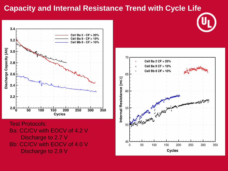
Capacity and Internal Resistance Trend with Cycle Life
Test Protocols:
Ba: CC/CV with EOCV of 4.2 V
Discharge to 2.7 V
Bb: CC/CV with EOCV of 4.0 V
Discharge to 2.9 V

Challenges with Cell Safety Features
27
Overcharged cell (fresh cell) with
delayed CID activation
Burned material
Anode surface of fresh (not cycled)
externally shorted cell
Anode of Fresh cell
Cell
exhibited
PTC
activation
Cell header (underside) showing charring
Anode showing charring
Cell with normal CID
activation
Approaches for Safe Designs for Use and
Transportation
• Use within manufacturer’s spec for voltage, current and temperature
OR
• Qualify with ample margin to requirements;
•Reducing voltage range used by application increases battery life, health and safety
• Complete characterization of performance and safety of lithium-ion cells and batteries should be carried out to carve out the baseline (qualification of design)
• Test stringently and extensively in the relevant configuration and environment to understand and characterize the safety controls and their limitations.
• Carry out high fidelity thermal analysis and design with best heat dissipation paths
28

Approaches for Safe Designs for Use and Transportation
Prevent Cell to cell thermal runaway propagation
• Cell to cell spacing; barriers between cells, etc. to prevent cell to cell
thermal runaway in the unlikely event of single cell thermal runaway.
• Use of extinguishers and other fire suppression methods installed
internal to battery container.
29
Methods to Determine Module Health Before
Second Life
Test and Destructively Analyze sub-module:
Using high fidelity thermal analysis for the battery/module design, the
module exposed to worst case thermal deviations should be chosen for
testing (as it will not be reused)
Carry out voltage, capacity and internal resistance/ac impedance tests
Carry out cell to cell interconnects’ integrity tests, complete visual
inspection and voltage measurements on each cell /cell bank
Disassembly of module followed by measurement of cell voltage,
capacity of individual cells, internal resistance and ac impedance tests
Disassembly of cells to study electrodes and electrolyte; three electrode
cell studies
Safety tests at the module and cell level to study any variations in safety
characteristics between used and baseline values (inclusion of ARC
along with electrical safety tests will add value)
30

Methods to Determine Module Health Before and
During Second Life
For Modules to be reused:
• Visual inspection (should include internal component inspection),
voltage, capacity, internal resistance/ac impedance
• Functional checks for proposed new second-use application and
environment – run profiles in the relevant environment to confirm
that module can perform as required
• Functional checks through complete process of assembly and after
assembly into stationary energy storage configuration for utilities.
• Continuous monitoring of health of the cells, modules, battery and
system to look for anomalies – allows for early problem detection
• Confirm that charger is suitable for the age of the battery
31

Summary
32
• Complete characterization of performance and safety of lithium-ion cells and
batteries should be carried out to carve out the baseline (qualification of
design)
• Test stringently and extensively in the relevant configuration and
environment to understand and characterize the limitations.
• Use Stringent screening methods for cells and batteries.
• Being vigilant of off-nominal behavior and recognizing this during the
life of the battery is a critical part of removing defective cells/batteries from
service before they go into a catastrophic failure mode. More important for
long term usage batteries.
• Lastly, usage limits, appropriate monitoring and control, cell balancing
and thermal design are key to prevent subtle defects from turning into
nucleation sites for larger fault conditions.
• Analysis and modeling are ways to lower cost of testing large modules
and batteries; however, full scale safety testing should be carried out with
the final full scale battery design
• Test, design, retest, redesign,…..dynamic pattern is required for
confirmation of safety

Acknowledgment
Texas A&M University team for current collaborations with UL:
Prof. Partha Mukherjee
Daniel Robles
Chien-Fan Chen
33

THANK YOU.