sam turbo industry pvt limited - sampumps.com · sam turbo industry pvt limited ... the design...
TRANSCRIPT

1
INSTRUCTIONS ON INSTALLATION, OPERATION AND MAINTENANACE FOR
SAM TURBO PUMP TYPE “TCH+N”
SAM TURBO INDUSTRY PVT LIMITED NEELAMBUR, COIMBATORE-641014, INDIA

2
EXTRA HEAVY DUTY
CHEMICAL PROCESS PUMPS AMERICAN NATIONAL STANDARD ANSI B 73.1 1974 (Formerly to AVS Dimensions)
DESIGN TURBO ‘TCH’ series are centrifugal pumps of horizontal, end suction, single stage, centerline, discharge design. This series includes design features to facilitate installation, maintenance and also maximum dimensional interchangeability. This range covers 32 pump sizes (ANSI covers only 15 sizes) with interchangeable mounting Dimension, size, location of suction and discharge nozzles, Impeller, shaft, base plate and foundation bolt holes etc. They are basically designed as a reliable equipment for handling corrosive liquids with/ without solid particles. PRESSURE AND TEMPERATURE LIMITS PRESSURE LIMITS The design pressure of the casing including Stuffing Box and Gland is as per pressure-Temperature rating of ANSI B16.1 Class 125 or ANSI B16.5 class 150 flanges for the material used. Casing, Stuffing Box and gasket is designed to withstand a hydrostatic test pressure of 1.5 times maximum design pressure corresponding to 40°C for 10 minutes for the material of constriction used.
FOR PUMPING Acids Alkalis Corrosive Slurries Hydrocarbons Etc., TECHNICAL DATA Pump Capacity - Upto 800 M3/Hr Pump Head - Upto 230 M Temperature - Upto 260°C Working Pressure - Upto 26 Kg/Cm2
Speed - Upto 3000 rpm TEMPERATURE LIMITS Cast iron material pumps shall be limited to temperature of 110°C. Carbon steel and other stainless steel material can be used up to 180°C. With provision of stuffing box jacketing, the pump can be used up to 260°C. However for normal application with standard construction the maximum temperature is limited to 110°C. FLANGES Suction and discharge nozzles are designed with flange dimensions confirming to ANSI B16.1. class 125lbs Cast Iron or ANSI B16.5 class 150lbs steel standards as to pitch circle, number and size of bolt holes etc. As an option class 250lbs cast iron Flanges and class 300lbs flange can be offered suitable to pressure-temperature limitations for the material of construction used. DIRECTION OF ROTATION TCH Series are with clock-wise direction of rotation when viewed from coupling end.

3
RANGE CHART

4
SAM TURBO INDUSTRY PVT LTD NEELAMBUR, COIMBATORE-641 014
WARRANTY WE WARANT THAT THE PUMP SUPPLIED BY US IS FREE DEFECTIVE
MATERIAL AND FAULTY WORKMANSHIP. THIS WARANTY HOLDS GOOD
FOR A PERIOD OF 12 MONTHS FROM THE DATE OF COMMISIONING OF
THE EQUIPMENT OR 18 MONTHS FROM THE DATE OF DESPATCH FROM
OUR FACTORY, WHICHEVER IS EARLIER.
OUR LIABILITY IN RESPECT OF ANY COMPLAINT IS LIMITED TO
REPLACING PART/PARTS FREE OF CHARGE EX-WORKS OR REPAIRS OF
THE DEFECTIVE PART/PARTS ONLY TO THE EXTENT THAT SUCH
REPLACEMENT/REPAIRS ARE ATTRIBUTABLE TO OR ARISE SOLELY
FROM FAULTY WORKMANSHIP OR DEFECTIVE MATERIAL.
WE WARRANT THE MATERIALS FOR THE CHEMICAL COMPOSITION AND
MECHANICAL PROPERTIES OF THE RELEVANT STANDARD ONLY AND
NOT FOR CORROSION AND EROSION.
THE WARRANTY HOLDS GOOD ONLY FOR THE PRODUCS
MANUFACTURED BY US.
SAM TURBO INDUSTRY PVT LTD

5
CONTENTS
GENERAL
1 FORWARD AND GUARANTEE
2 DESCRIPTION OF PUMP
3 ERECTING THE PUMP
4 LAYING THE CONNECTING PIPINGS
5 STARTING AND STOPPING
6 SUPERVISION AND MAINTENANCE
7 DISMANTLING AND ASSEMBLING
8 SPARE PARTS
9 CROSS SECTIONAL DRAWINGS
10 TROUBLE – CAUSE - REMEDY
PLEASE FURNISH COMPLETE NAMEPLATE DETAILS, NAME OF THE PARTS,
PART NOS AND MATERIAL OF CONSTRUCTION WHILE ORDER SPARE PARTS
FOR THE PUMPS

6
GENERAL: This booklet covers instructions for following TCH+N Model Pumps.
POWER SERIES PUMP MODELS
T 15
25/160 25/160-I 40/160 50/160 25/180 25180-I 40/180 50/180 25/200
25/200-I 40/200
T 18
25/230 40/230 50/230 80/230 100/230 25/260 40/260 50/260 80/260 100/260 40/300 50/300 80/300 100/300
T 22
150/300 80/360 100/360 150/360 200/360 80/400 100/400 150/400 200/400

7
1. FORWARD AND GUARANTEE:
Inspect the pump and accessories upon arrival for any damage or loss which may have been incurred during shipment. Report and damage or shortage immediately to the Sales Department of our Factory.
We are not liable for damage incurred through failure to observe the instructions for erection and operation. In this connection please refer to our general terms of delivery for Centrifugal Pumps.
During the Period of guarantee, repair work and modification shall be carried out by our fitters only, or following our approval in writing; it may be done by you. If contrary to our Acknowledgement of Order, you wish to use the Pump for a different service please ask for our acceptance. Otherwise the guarantee given for this pump will not be valid.
2. DESCRIPTION OF PUMP :
2.1 Pump Name plate/Ordering Spare Parts/Spare Parts List: Every TCH+N Pump has a name plate giving the following details: Pump Type Serial Number Duty Conditions (Head, Capacity) Motor Details etc
While you correspond with us for your requirement of spare parts or for any technical information, please always quote the above details in your letter.
2.2 CONSTRUCTIONAL FEAUTERS :
Type TCH+N Centrifugal Pumps are basically, Horizontal, Single Stage, Volute casing with single axial Inlet. Top centre line discharge with semi open impeller construction and hence capable of handling liquids with solid particles of small sizes.
The Back-Pull-Out design permits dismantling of the complete bearing unit without disturbing the piping connections and drive. The pumps are available for capacity range up to 800 M
3/Hr, for differential head up to 230 Metres and temperature up to 260°C.
2.3 DIRECTION OF ROTATION :
Clockwise, pump viewed from driven end.

8
3. ERECTING THE PUMP :
3.1 Assembling the set on the Base plate :
3.1.1 If the assembly of the pump with the driver is done on a common base plate in our works, the whole Set will be carefully mounted and aligned. It is necessary to check once more the alignment of the coupling before putting the pump into operation.
The eye bolts which may be fitted to the driver must never be used to lift the complete set as they are meant to carry the weight of the driver only.
3.1.2 If you furnish the driver yourselves, the clearance between the motor and pump coupling
halves as shown on the arrangement drawing must be strictly observed.
Difference in .Level between the shaft centre lines of pump and driver must be equalized by suitable packing (Plane parallel shims) When the pump and motor holding-down bolts are finally secured, care must be taken to avoid distortion.
3.2 Leveling the Base plate, aligning the Couplings:
To check whether pump and motor shafts are in perfect alignment proceed as follows:
3.2.1. Level accurately the base plate which carries the complete set with the aid of a spirit level. Place metallic Packing between the base plate and foundation close to the foundation bolt holes. To prevent sagging of the base plate, place metallic packing-if required- also between the foundation bolt holes. After leveling the base plate, fill up the foundation bolt holes with the bolts inserted-with a quick-setting cement compound. After the grout has set, tighten nuts crosswise. Check once again the alignment with a spirit level.
After levelling the pump set, measure the axial clearance between the two coupling halves. Axial clearance between two corresponding points should remain same when both couplings are turned through an angle. Maximum permissible tolerance is 0.10mm.
3.2.2. After leveling the pump set, measure the axial clearance between the two coupling halves. Axial clearance between two corresponding points should remain same when both couplings are turned through an angle. Maximum permissible tolerance is 0.10mm.
The radial alignment is achieved by dial gauges, the permissible tolerance being 0.10mm provided that the type of coupling is such as to allow this check (figure 1a). Otherwise a coupling aligner must be used, permissible tolerance 0.10mm (figure 1b).

9
case 1: as the gap progressively increases the axial dial gauge (Da) plunger comes out and we get a negative reading.
Case 2: as the gap progressively decreases the axial dial gauge (Da) plunger pushed in and we get a positive reading.
In the display unit the user can decide the horizontal or vertical program, and similar to reverse peripheral method the distances ‘a’,’b’, and ‘c’ are asked.

10
3.2.3. After leveling the pump set, measure the axial clearance between the two coupling halves. Axial clearance between two corresponding points should remain same when both couplings are turned through an angle. Maximum permissible tolerance is 0.10mm.
3.3 Grouting the Base plates:
Grout base plate fully with concrete through the grouting. Holes provided for this purpose, leaving no cavities.
After the grout has set, recheck the alignment of the coupling.
4. LAYING THE CONNECTING PIPINGS : 4.1 GENERAL
After grouting the base plate, the pipe work may be connected. The diameters of the piping are not determined by those of the pump and suction branches. On short delivery pipe runs the diameter should be such that the pipe resistance constitutes, but a small portion of the delivery head. For long pipe runs the most economic pipe diameter must be assessed in each particular case.
The flow velocity in the suction piping should be 1.5 to 2.5 mts/sec., for normal cases but should not exceed 3 metres/sec.
Unfavorably installed pipe runs, especially on the suction side (i.e. bends in various planes immediately before the suction branch) can affect the performance of the pump.
As the pump branches should not absorb pipe forces and moments, The pump must not be used as a locating point of the pipe work.
Once the flange bolts have been loosened, the flanges must not yield more than the amount corresponding to the gasket thickness, nor must they be out of the parallel nor bear against each other under stress. See that the flange gaskets do not extend into the bore of the piping. Clean carefully all pipe parts, valves and fittings and pump branches prior to assembly.
ATTENTION
After connecting up the piping, the coupling alignment must be rechecked. It must be possible to turn the rotor easily by hand. In case of inadequate alignment bearings, coupling and shaft seal may get damaged prematurely. In accordance with safety prescriptions the coupling must be protected with a guard against contact.

11
4.2 Suction and Feed Line:
4.2.1 To prevent collection of gas the SUCTION LINE must be horizontal or rise continuously all
the way to the pump. The FEED LINE, however, must be horizontal or shown a gradual slope towards the pump.
4.2.2 The Suction line must be completely airtight and laid so that it can be properly vented
(Figure 2). If tapers are required, eccentric ones must be used. 4.2.3 The inlet bore of the suction pipe should be set as deeply as possible below liquid level
and be provided with a foot valve fitted with a suction strainer. The foot valve must, however, be far enough away from the bottom to avoid inlet losses becoming too great and thereby lowering the performance.
4.2.4 The isolating valves in the suction or feed line must remain fully open during the operation
and must NEVER be used for regulating.
They should be mounted with the spindle in the horizontal or in the vertical downward position to avoid air pockets forming in the spindle cap. To avoid ingress of air, it is advisable to use isolating valves with sealing water connection or with a water seal.

12
4.3 Delivery Line :
Install gate valve or an output control valve in the delivery line as close to the pump branch as possible. it is recommended to install a non return valve between pump branch and regulating valve (figure 2), thus protecting the pump against reverse rotation and further more the pump and the foot valve against water-hammer which may occur in case of sudden shut-down.
4.4 Sealing Liquid Lines :
For the sealing liquid line connection(s) please refer to the arrangement drawing. The service data (like pressure, flow rates etc) for external sealing are stated in our Acknowledgement of Order. If only a sealing liquid INLET is provided for, a regulating valve should be installed in the inlet line. If an INLET and OUTLET line (discharges into the open air) is provided for, the regulating valve is to be fitted in the outlet line.
4.5 Cooling Water Lines :
For the cooling water line connection please see the arrangement drawing. Connect the cooling water lines so that the inlet is at the lower connection. thus ensuring that the cooling chamber is vented and completely filled.
4.6 Heating Lines :
For the heating line connections please see the arrangement drawing. The service data (like pressure, temperature, flow rates, etc.) are given on our Acknowledgement of Order. If steam is employed for heating, the inlet should be provided on the top in order that the condensate may flow off through the outlet at the bottom.

13
In the event of liquid being used for heating, the inlet should be provided at the lower connection, thus ensuring that the heating chamber is vented and completely filled.
4.7 Vacuum Equalizing Pipe (and Sealing Liquid Pipe):
If the pump draws from a system under vacuum, an equalizing pipe must be connected from the highest point of the suction line, however, as close to the suction branch as possible, to the top of the feed tank to keep gas bubbles that might have been entrained in the flow from entering the pump (figure 3).
The line should be fitted with an isolating valve which should be closed only for maintenance work on the pump set. Apply sealing liquid (external sealing) to the shaft seal to prevent entry of air.
5. STARTING AND STOPPING: 5.1 Precautions to be taken before Operation
5.1.1 Stuffing box
Make sure that the stuffing box has been properly packed and above all that the gland has not been tightened too firmly as, otherwise, damage will occur to the packing and the shaft sleeve. See to it that it is not tightened unevenly and does not rub on the shaft. The shaft must run freely, it must be possible to turn it by hand.
5.1.2 Oil Level
Check the oil level in the bearing housing (See sub-section 6.2)
5.1.3 Direction of rotation:
The direction of rotation must correspond to the direction arrow on the volute casing. If the direction cannot be checked while, the machine is disconnected; the motor may be started for a moment only.
On pumps equipped with mechanical seals this check may be carried out only with the machine disconnected.
Wrong direction of rotation will soon do damage to the pump. 5.2 Starting - up:
5.2.1 The isolating valve in the feed line (and, if there is any, the valve in the vacuum Equalizing pipe) should be fully open. The regulating valve in the delivery line, however, should be closed, or in the case of automatic operation, the full back pressure should be on the non-return valve.
5.2.2 Make sure that there is a flow in the pipes supplying the external sealing liquid, the cooling
water for the shaft seal and, if required, the cooling water for the oil bath. Do not switch on motor until then.
5.2.3 If the delivery pressure does not rise continuously as speed increases, stop the set and prime once more carefully.

14
5.2.4 Once the pump has run up to working speed, open the regulating valve in the delivery line slowly until the required service data are reached.
5.2.5 Prolonged operating against closed regulating valve in the delivery line may lead to destruction of the internal pump parts and must therefore be avoided.
5.2.6 An alteration of the service data which might become necessary may be effected only with the aid of regulating valve in the delivery line.
PARTICULAR CARE SHOULD BE TAKEN
That the driver does not get overloaded if the weight of the liquid handled is greater than that originally assumed, that the available suction head is still sufficient in case of larger flow rates or, alternatively.
That the suction lift to be overcome by the pump is not too high, as otherwise damage due to cavitation will occur.
5.2.7 When starting up automatically operated plants, all isolating valves, hence the delivery gate valve too, must be kept open.
5.3 Stopping:
5.3.1 If there is no back flow preventer (non-return flap, non-return valve, etc) close the regulating valve in the delivery line. Do not switch off motor until then.
5.3.2 Close isolating valve in the feed line only if necessary.
5.3.3 Once the pump has completely cooled down, shut off the external sealing and cooling Water supply. If pump draws from a vacuum tank, close vacuum equalizing pipe. However, do not shut off the sealing liquid supply.
5.3.4 If a vacuum gauge without relief valve. is attached to the suction branch of the pump, then it must be isolated before stopping the pump set.
5.3.5 If as a result of prolonged shut-down a change in the concentration of the liquid, crystallization, or solidification etc., can be anticipated, drain pump and, if necessary, flush with a suitable liquid.
5.3.6 If there is danger freezing up during prolonged shut-down periods (e.g. where the pump set is located in the open) the pump including the cooling chamber, heating chamber, etc., must be drained.
5.4 Re-Starting: Before-starting the set, take care that the pump shaft is at rest and does not rotate backwards. Starting with the shaft rotating in opposite direction may lead to shaft damage.
6. SUPERVISION AND MAINTENANCE:
6.1 General : 6.1.1 Even, smooth running of the pump rotor is essential.

15
6.1.2 When delivering from a tank, the liquid level must always be well above the inlet opening.
6.1.3 The parameter as indicated on the pump nameplate must not be exceeded while operating.
6.1.4 The stuffing box must always drip slightly to remove friction heat from the sealing faces. If the leakage intensifies and does not decrease when the gland is tightened evenly, the packing must be renewed (see sub section 6.3.1). Also take care that the surface of the shaft sleeve is still perfectly smooth. Otherwise change shaft sleeve.
6.1.5 If a pump shaft is equipped with a mechanical seal, practically no attention is required. During the running-in period occasional slight leakage may occur (See sub-section 6.4).
6.1.6 When handling hot liquids (pump design 'With stuffing box cooling') pay attention to the flow of the cooling water for the shaft seal and the oil bath cooling, if any. The cooling water flow should be adjusted so that the heating of the cooling water does not exceed 15°C.
Sudden changes in temperature of the liquid handled from cold to hot or vice versa should be avoided.
All pumps are equipped with a constant level oiler (see sub-section 6.2), merely check that there is oil in its container.
6.1.7 The bearing temperature must not exceed 80°C.
6.2 Bearings and Lubrication : The pumps are supplied by us without oil charge.
When the pump is put into operation after prolonged shut-down, flush bearings and bearing housing with petrol or benzol in order to remove impurities. During the flushing procedure rotate the shaft slowly.
Fill the bearing housing with oil through the inlet hole (Amount of oil 0.4, 0.6, 0.8 litres according to pump size). As constant level oiler is furnished by us this must be screwed into the appropriate tap hole.
FIRM Lubricating oil for temperature up to 80°C
Speed up to 1500 rpm Speed over 1500 rpm
Indian Oil Servo system 150 Servo system 68
Hindustan Petroleum ESSTIC 55, TERRESSO 56
ESSTIC 50 TERRESSO 52
Mobil
MOBIL VACTRA Oil Heavy MOBIL D.T.E Oil Heavy Vac HLP 49
MOBIL VICTRA Oil Heavy Medium MOBIL D.T.E Oil Heavy Medium Vac HLP 36
Shell Shell Vitrea Oil 33, Shell Oil 33
Shell Vitrea Oil 31, Shell Tellus Oil 29

16
TO INSTALL A CONSTANT LEVEL OILER AS BELOW:
1. Unscrew upper screw sub assembly from lower sub assembly. (Refer Fig.1)
3. Once lower sub assembly is fixed, tighten
locknut to ensure that CLO is 90° with respect to
ground.
5. Once initial oil level is maintained in pump,
take upper sub assembly, reverse, it and put
it oil in dome through the hole by using a suitable
funnel (3/4th full) DO NOT UNSCREW DOME
from the sub assembly to fill oil. (Ref.Fig.5)
2. Fix lower sub assembly (elbow type) on
pump. Please note Pump has two tappings. One
tapping is for CLO and other is a drain, which is
at a lower height.
4. Fill oil in pump with a can. Oil should be filled
either by opening breather of pump or from the
lower sub assembly. (Ref. Fig.4)
6. Once oil is filled dome, reverse and screw it on
the lower sub assembly. DO NOT
OVERTIGHTEN.Some bubbling will take place,
this is O.K., bubbling will stop once oil has reached
its LEVEL. i.e. X (Ref. Fig.6)

17
7. Once bubbling has stopped the pump should be
started. CLO will automatically maintain oil level in
pump. Refill oil whenever oil level in the dome
goes below level Y ref.Step-1,5,6.
Note: 1-In case of pump is already full of oil before installing CLO, it is recommended to check oil level in sump as per step 4.
In case there is excess oil, drain it out and bring it to half the elbow overfilling oil will cause oil to
overflow from above the holder resulting in oil
leakage.
Note-2: keep vent hole of breather in pump clean, if
it is chocked it will cause leakage from oil cup.
Grease Lubrication The grease-lubricated bearings have been lubricated before shipment. For these bearings following roller bearing greases are recommended which are available in the market. Grease specifications
For lubrication of our machines we recommend the lubricants shown on this lubrication table or equivalent lubricants.
The sequence of the lubricant suppliers is not inticative of the quality rating of their grades. Each of these companies maintains a technical service whose engineers are at all time at your disposal and without obligation on your part.
Fill the bearing housing through the inlet hole with oil until the oil becomes visible in the screw-in-elbow. Next fill the oil container. Now so much oil flows from the container into the bearing housing until the requisite oil level is reached. As long as there is oil in the container, the oil level in the bearing housing has the requisite height.
In the case of new bearings, renew the oil after about 200 hours and then about once a year, if the bearing temperature is always below 50°C and there is only small risk of contamination. If the bearing temperature is up to 80°C and if there is danger of contamination, the oil should be renewed about every six months.
Name of the firm Speed 1450 rpm Speed 2900/3600 rpm
INDIAN OIL SERVOGEM 3 SERVOGEM 2
CALTEX STARFAK 3 STARFAK 2
HINDUSTAN PETROLEUM
NATRA 3 or LITHON 3
NATRA 2 or
LITHON 2

18
6.3 Stuffing Box :
6.3.1 Packing :
The pumps are delivered by us with the stuffing boxes in unpacked condition. Take care that the stuffing box is correctly packed. If, after prolonged operating time, the inserted packing material is worn it must be completely removed as, otherwise the running surface of the shaft sleeve may become rough. Should the shaft sleeve be damaged, this must be replaced too. If no pre-shaped packing are available, cut packing material to suitable length, e.g., with a gauging plug of the same diameter as the shaft sleeve.
The joints of the packing rings must be staggered. A gap of 1 mm between the joints after fitting will, in any case, prove less detrimental than squeezing too long pieces together (see figure 5a). Pre-shaped rings must be bent up sidewise and slipped over the shaft sleeve (figure 5b)
When re-packing, take care that a packing material is used which suits the operating conditions.
Unless the pump is dismantled, cut to halves pH~-pressed packing rings for installation by straight Cuts.
For running in the pump tighten gland at first only slightly, even if the leakage is greater than what is normal. After a certain running-in period the gland should be tightened evenly until there is only slight leakage from the stuffing box.
6.3.2 Sealing : Sealing of the stuffing box with the liquid handled (self sealing) or with a liquid from an outside source (external sealing) which suits the particular service conditions, and thus the use of a lantern ring is necessary in the following cases.
a) For suction lift duties and suction heads of up to 0.5 Kg/cm2
or for liquids drawn from vacuum tanks (with self-sealing or external sealing, depending on the service conditions).
b) For liquids with temperatures near boiling point (with external sealing or self sealing, depending on the service conditions).

19
c) For handling explosive, poisonous or evil smelling liquids (external sealing imperative)
d) For handling abrasive liquids or liquids which tend to crystallize (external sealing imperative)
In all other cases the lantern ring is unnecessary. It is then replaced by two packing rings.
6.3.3 Stuffing box cooling :
If a liquid being pumped evaporates at the pumping temperature, then the stuffing box should be cooled. This prevents the packing from running dry due to the evaporation of the liquid handled.
For location of the cooling water connections, see ARRANGEMENT DRG.
The regulation valve, which should be placed in the outlet line, is to beset in such a manner that the heating up of the cooling water does not exceed 15°C.
6.4 Mechanical Seal :
Concerning the pumps fitted with a mechanical seal, we refer the special instructions for installation, provided by seal manufacturers.
6.4.1 General :
The life of a mechanical seal depends on various factors such as cleanliness of the liquid handled, its lubricating properties etc., Due to diversity of operating conditions it is, however, not possible to give definite indications as to its life. As dry running of a mechanical seal, even for a few seconds, must be avoided, never operate the pump without liquid.
When renewing or changing the mechanical seal, check pump shaft for true running and take care that the shaft sleeve surface is in perfect condition in the area of the mechanical seal.
For more particulars please see the instructions for installation and maintenance of mechanical seals given by the concerned seal manufacturers.
If the shaft seal is to be converted from packing to mechanical seal at a later date, this is feasible for a fair number of standard mechanical seals without re-machining the stuffing box chamber.
Shaft sleeve and the gland (suitable to the seal to be installed by you) along are to replaced. These can ordered with us as extra components, giving complete details about the mechanical seal you propose to install.
6.4.2 Flushing of the Mechanical Seal : Evaporation of the liquid between the rotary seal faces, hence the risk of dry-running must in all cases be avoided. Therefore we recommend flushing of the seal; this is indispensable when the temperature of the liquid handled is in the vicinity of the boiling point.
If abrasive particles can get to the seal faces, flushing must also be provided. The smaller the particles the easier it is for them to get lodged between the contact faces. This will destroy the faces and lead to breakdown of the seal.

20
The flushing is achieved by means of circulating line (Self-flushing) or through an external flushing system (external flushing). To regulate the flushing liquid a throttling element (e.g. a flow controller) can be installed in the circulating line.
The required pressure of the external flushing liquid depends on the type of pump and service conditions.
7. DISMANTLING ANS ASSEMBLING:
7.1 General : If the pump has been maintained and serviced carefully, breakdowns which necessitte the pump being dismantled should not occur. If, however, faults occur, the cause should be located before dismantling if possible.
If technical personnel are not available, we recommend that you request the service of an erection engineer or despatch the pump to our works for checking.
If the pump is being stripped by yourselves, all parts must be handled with greatest care, avoiding blows and shocks.
All parts must be carefully cleaned, tested for wear and if necessary, reconditioned or replaced with new parts. If new joints have to be made, it must be ensured that the correct measurements are observed (see sub-section 9.0)
After assembly, the rotor must turn easily by hand. Otherwise the bearings, coupling and shaft may get damaged prematurely.
7.2 DISMANTLING : The pumps offered are of back pull out type design. Hence while dismantling pump, casing will remain in its place with the suction and delivery piping. The rotating assembly can be pulled back easily. If spacer couplings are used, then the driver also need not be removed, thus enabling easy re-assembling of the pump without affecting the alignment. We recommend to match-mark the parts before removing the spacer so as to 'ensure the original state of mounting when re-assembling.
The coupling halves should only be mounted and dismounted by means of suitable extraction devices
7.2.1 Drain the volute casing of the liquid handled and bearing housing (36.7) of oil
7.2.2 Remove spacer coupling or if there is no such coupling loosen driver and move it aside.
7.2.3 Loosen sealing liquid and, coolant pipes and undo the fastening screws on the support Foot (91.13)
7.2.4 Undo stud nuts on volute casing.
7.2.5 Using the two fixing screws on the S.Box cover withdraw the S.Box cover (17.3) bearing lantern (35.6) and bearing housing (36.7) along with the complete rotor (figure7).
7.2.6 Remove the Impeller by unscrewing It from the shaft.
7.2.7 Removal of mechanical seal
7.2.7.1 The rotating elements of the mechanical seal can be extracted together with the shaft sleeve (53.6) from the impeller side.
7.2.7.2 After undoing the fixing screws, separate Stuffing box cover (17.3) from bearing lantern (35.6)

21
7.2.8 Removal of packed stuffing box
7.2.8.1 After undoing the fixing screws, separate stuffing box cover (17 .3) together with packing, lantern ring (46.10) and gland (46.4) from bearing lantern (35.6)
7.2.8.2 Remove shaft sleeve (53.6), gland (46.4) and deflector (51.9) (The shaft sleeve can be removed by means of an extractor disc, which we supply upon request, using a normal extraction device).
7.2.9 Remove Outer Bearing Cap, drive side (37.21).
7.2.10 Drive out carefully pump shaft (22.3) with bearing towards drive side.
7.2.11 Heat the bearing and extract it see that the heat is not transmitted to the shaft.
7.2.12 If the bearing housing lantern (35.6) or the radial shaft seal (43.13) need not be changed, the bolts connecting the bearing housing lantern (35.6) to the bearing housing (36.7) should not be loosened, as this joint is sealed with a liquid sealant, otherwise these seal faces must be thoroughly cleaned and provided with liquid seal before reassembly: Clean all dismantled parts and check them for wear.
7.3 ASSEMBLING :
7.3.1 For assembly proceed in reverse sequence.
7.4 DISMANTLING ASSEMBLY :

22
After mounting the shaft check the axial float of the rotor 0.1 - 0.7mm with grooved ball bearing on the coupling and the pump side. 0.1-0.5mm with a double row angular contact ball-bearings on the coupling side and single row deep groove ball bearing on the pump side (Fig .8). Should new bearings be mounted on the shaft, they must first be heated upto about 80°C in an oil bath. The bearings must bear against the shaft shoulders. The bearings installed in our works have normal clearances. However, the use of bearings with c3-play is permissible. NOTE: After mounting the S.BOX cover (17.3) on to the bearing lantern (35.6), tighten it against the bearing lantern by means of the two Fixing screws and a locking nut. Pay attention to the O-rings and gaskets. If they are to be changed see that the joint thickness is maintained.
By adjusting the screws provided in the outer bearing cap the rotor assembly can be moved axially so that the front clearance 'C' can be maintained carefully to achieve the pump performance.
7.5 Sealing :
When packing, see that the lantern ring (46.10) is located underneath the sealing liquid hole. When square section packing rings are used, it is essential to install first three packing rings and only then the lantern ring. The required sealing liquid pressure in the case of external sealing depends on the pump type and the service conditions since no general stipulations can be made please ask us about the required pressure, unless it is stated in our acknowledgement of order, please quote also the service data, such as capacity, head, nature of liquid etc.

23
8. SPARE PARTS FOR ‘TCH+N’ PUMPS : (Available from local market)
PUMP MODEL
25/1
60
25/1
60-I
40/1
60
50/1
60
25/1
80
25/1
80-I
40
/180
50
/180
25
/200
25
/200
-I 40
/200
25
/230
40
/230
50
/230
80
/230
10
0/23
0 25
/260
40
/260
50
/260
80
/260
10
0/26
0 40
/300
50
/300
80
/300
10
0/30
0 15
0/30
0 80
/360
10
0/36
0 15
0/36
0 20
0/36
0
80/4
00
100/
400
150/
400
200/
400
CODE NO PART NAME PART SIZES
41.2 GASKET-Volute Casing / Stuffing
Box Cover
159x172x1.5
178x192x1.5
210x223x1.5
233x251x1.5
273x291x1.5
313x331x1.5
313x
331x
1.5
360x378x1.5
403x421x1.5
36.7 Bearing Housing T 15 T 18 T 22
Amount of oil in bearing housing 0.4 Litres 0.6 Litres 0.8 Litres
33.13 Pump side 6306 6309 / 6311 * 6313
Bearing
33.3 Coupling side 3305 3309 / 3311 * 3313
43.3 Coupling side 22x32x7 40x55x7 60x75x8
Oil Seal
43.13 Pump side 30x72x8 45x55x7 65x75x10
41.03 Flat Gasket-Sleeve 26x32x1 34x41x1 55x62x1
41.04 Flat Gasket-Imp.Nut 20x28x1 28x38x1 45x57x1
47.3
Stuffing box size Packing No.of rings x length
8 x 8 5 x 135
10 x 10 5 x 173
12.5 x 12.5 5 x 245
* APPLICABLE ONLY FOR TCH+N HS PUMPS

24

25
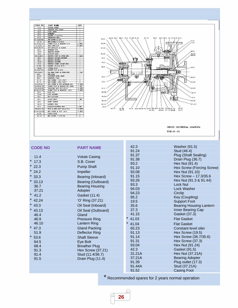
9. SECTIONAL DRAWINGS :
26
CODE NO PART NAME 11.4 Volute Casing * 17.3 S.B. Cover * 22.3 Pump Shaft * 24.2 Impeller * 33.3 Bearing (Inboard) * 33.13 Bearing (Outboard) 36.7 Bearing Housing 37.21 Adopter * 41.2 Gasket (11.4) * 42.24 ‘O’ Ring (37.21) * 43.3 Oil Seal (Inboard) * 43.13 Oil Seal (Outboard) 46.4 Gland 46.9 Pressure Ring 46.10 Lantern Ring * 47.3 Gland Packing 51.9 Deflector Ring * 53.6 Shaft Sleeve 64.5 Eye Bolt 68.4 Breather Plug 91.3 Hex Screw (37.21) 91.4 Stud (11.4/36.7) 91.5 Drain Plug (11.4)
42.3 Washer (91.5) 91.24 Stud (46.4) 91.37 Plug (Shaft Sealing) 91.38 Drain Plug (36.7) 93.2 Hex Nut (91.4) 91.10 Hex Screw (Forcing Screw) 93.08 Hex Nut (91.10) 91.15 Hex Screw – 17.3/35.6 93.26 Hex Nut (91.3 & 91.44) 93.3 Lock Nut 94.03 Lock Washer 94.23 Circlip 95.2 Key (Coupling) 19.5 Support Foot 35.6 Bearing Housing Lantern 37.3 Inner Bearing Cap 41.15 Gasket (37.3) * 41.03 Flat Gasket * 41.04 Flat Gasket 65.23 Constant level oiler 91.13 Hex Screw (19.5) 91.14 Hex Screw (36.7/35.6) 91.31 Hex Screw (37.3) 93.04 Hex Nut (91.24) 42.3 Gasket (91.5) 31.21A Hex Nut (37.21A) 37.21A Bearing Adopter 91.39 Plug outlet (17.3) 91.44A Stud (37.21A) 91.52 Casing Foot
* Recommended spares for 2 years normal operation

27
10. TROUBLE - CAUSE - REMEDY : In the event of troubles we recommend to locate the cause using the following chart:
Trouble Cause-Remedy No.
1. Pump does not deliver 1 7 8 9 10 11 12 15 16 17 18 19 20 24 26 27 31 68 69 70
2. Pumps delivers at reduced capacity 1 2 3 4 5 6 7 8 9 10 11 12 14 15 16 18 19 20 21 23 68 69 70
74
3. Delivery performance reduced 1 3 7 9 10 11 12 14 15 20 21 23 24 59 65 69 74
4. Pump delivers too much 17 68 69 70
5. Delivery is interrupted 1 3 6 7 8 9 10 11 12 13 14 15 16 17 20 23 24 26 30 68 69
70 74
6. Pumps runs in reversed direction 64
7. Very noisy 1 2 5 6 7 8 11 12 14 16 20 21 23 66 67 68 69 70 74
8. Unsteady running of the pump 20 21 23 33 34 36 38 39 40 41 42 43 47 48 49 52 54 55 56
57 58 63 66 67 70
9. Pumping casing not leak proof 52 54 59 60
10. Excessive leakage from stuffing box 21 25 28 29 30 32 33 55 56 57 65
11. Fumes from stuffing box 23 24 25 26 27 28 29 32 45 46 65
12. Mechanical Seal Leaking 21 23 24 31 45 46 55 57 65 75
13. Pump rotor blocked in standstill position 23 49 50 52 54 58
14. Pump is heating up and seizing 23 24 25 26 27 28 30 32 43 45 46 49 50 54 55 56 57 58
15. Bearing temperature increase 20 21 23 33 34 36 37 40 41 42 43 44 45 47 48 49 50 52 54
55 57 63 66 67 70
16. Motor will not start 15 23 72
17. Motor is difficult to start 15 17 23 28 29 49 50 54 58 70 71 72
18. Motor is running hot burning out 15 17 23 28 29 43 58 68 69 70 71 72 73

28
10.1 Cause - Remedy : 1. Suction filter, foot valve clogged. 2. Nominal diameter of suction line too small. 3. Suction does not reach down far enough into the delivery liquid. 4. Ground clearance of suction too narrow 5. Too many bends in the suction line. 6. Shut-off valve in the feed line in un-favorable position 7. Incorrect layout of suction line (Formation of air pockets) 8. Valve (s) in the suction and/or feed line not fully open. 9. Screwed joints or flanges in the suction line not leak – proof 10. Ingress of air via leaking valves and fittings in the suction line (Stuffing box etc). 11. Suction lift too great. 12. Available NPSH too low (difference between pressure at suction branch and vapour pressure
too low). 13. Cut-out level for starter too low (In automatic plants0. 14. Delivery liquid containing too much gas and/or air. 15. Delivery liquid too viscous 16. Insufficient venting 17. Speed too high (number of revolutions of driver higher than nominal number of revolutions of
pump) 18. Speed too low (number or revolutions of driver lower than nominal number of revolutions of
pump). 19. Incorrect direction of rotation (electric motor, incorrectly connected, leads on the terminal
board interchanged). 20. Impeller Clogged. 21. Impeller damaged. 23. Separation of crystals form the delivery liquid (falling below the temperature limit/equilibrium
temperature). 24. Sealing liquid line/circulation line clogged. 25. Sealing liquid line contaminated. 26. Lantern Ring in the stuffing box is not positioned below the sealing liquid inlet. 27. Sealing liquid omitted. 28. Packing incorrectly fitted. 29. Gland tightened too much/slanted. 30. Packing material not suitable for operating conditions. 31. Mechanical Seal blocked; O-ring-rotating seal ring or stationary seal ring damaged. 32. Shaft sleeve/shaft worn in the region of the packing. 33. Bearing worn out. 34. Insufficient lubrication of bearings (also in case of automatic lubrication). 36. Specified oil level not maintained. 38. Oil quality unsuitable.

29
39. Rolling contact bearings incorrectly fitted. 40. Axial stress on rolling contact bearings (no axial clearance for rotor) 41. Bearings dirty. 42. Bearings rusty (corroded). 43. Axial thrust too great because of worn wear rings, obstructed relief holes. 44. Radial shaft seal ring has not much tension (local heating-up of shaft) 45. Insufficient cooling water chambers. 46. Sediment in the cooling water chambers 47. Alignment of coupling faulty or coupling loose. 48. Elastic element of coupling worn. 49. Foundation in correctly performed. 50. Base plate not rigid enough in the event of erection without foundation. 52. Pump casing under stress. 54. Pipe line under stress. 55. Shaft runs untrue. 56. Shaft bent. 57. Rotor insufficiently balanced. 58. Rotor parts touching the casing. 59. Unsuitable casing seal. 60. Casing screw not light enough 63. Vibration of pipe work. 64. Non return valve gets stuck. 65. Contaminated delivery liquid. 66. Delivery flow too small. 67. Delivery flow too great. 68. Pump unsuitable for parallel operation. 69. Type of pump unsuitable. 70. Incorrect designing of pump for existing operating conditions. 71. Voltage too low/power supply overloaded. 72. Short circuit-in the motor. 73. Setting of circuit-breaker for motor handled too high. 74. Temperature of the liquid too high. 75. Spring of the mechanical seal damaged.

30
SAM TURBO INDUSTRY PRIVATE LIMITED AVANISHI ROAD, NEELAMBUR, COIMBATORE - 641 014. Phone : +91422-3053555, (100 lines) WEBSITE : WWW.SAMPUMPS.COM EMAIL: [email protected]