savelight® control system - ff-automation
TRANSCRIPT

AutoLog SaveLight Technical Specification 6 (104)
AutoLog SaveLight Technical Specification v.1.2
AutoLog SaveLight
Technical Specification

AutoLog SaveLight Technical Specification 7 (104)
AutoLog SaveLight Technical Specification v.1.2
1 Introduction
1.1 Intelligent Street Light Management System
We are pleased to introduce the energy saving features and other benefits of intelligent
street light management system called “AutoLog® SaveLight” from Finnish company FF-
Automation.
Hosted server with remote web based user interface
Intelligent street light feeder pillars
AutoLog® SaveLight is a brand name for complete solution which includes the following
main parts: Intelligent street light feeder pillars; Hosted server with remote web based
user interface; GSM / GPRS based communication between feeder pillars and the server.
Over 20 cities in Finland are using AutoLog SaveLight system to save energy.
Lowered power consumption leads also to lowered CO2 emissions!

AutoLog SaveLight Technical Specification 8 (104)
AutoLog SaveLight Technical Specification v.1.2
1.2 Basic Operating Principle
Basic wiring and operation diagram of SaveLight Feeder Pillar
AutoLog SaveLight Feeder Pillar unit controls street lights according to measured
lightness and internal clock & calendar. Street lights can be controlled also manually from
web interface or with GSM phone.
AutoLog SaveLight feeder pillar gets power input from power grid’s transformer station.
Normally the power input is 3 x 230 VAC. There are 3-phases called L1, L2 and L3 and
also common N. One street light line can include tens or even hundreds of street light
poles. Street light lines can be grouped together to have one 3-phase control group or
there can be 3 individually controlled street light lines so that every phase is controlled
separately.
SaveLight feeder pillar can be equipped with components which allow 50A or 100A
current supply per phase. So the feeder pillar can control 3 x 11kVA (3 x 230VAC * 50 A)
or 3 x 22kVA (3 x 230VAC * 100 A) street light lines. If for example street light line
includes 200 W light bulbs one 11kVA line can control (11000 / 200 =) about 55 light
bulbs. It also depends the internal resistance of the cable, how many lights can be
controlled per line.
AutoLog SaveLight Technical Specification 9 (104)
AutoLog SaveLight Technical Specification v.1.2
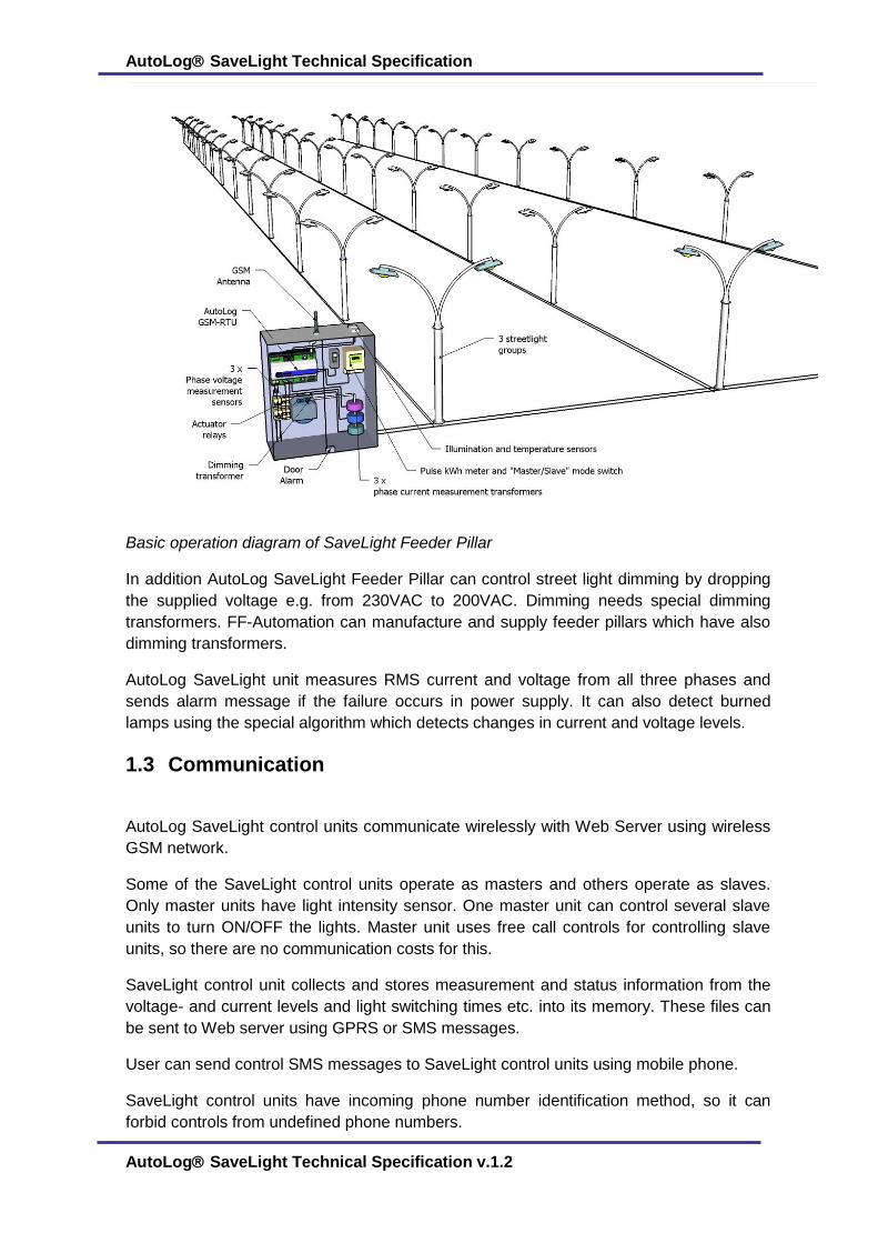
Basic operation diagram of SaveLight Feeder Pillar
In addition AutoLog SaveLight Feeder Pillar can control street light dimming by dropping
the supplied voltage e.g. from 230VAC to 200VAC. Dimming needs special dimming
transformers. FF-Automation can manufacture and supply feeder pillars which have also
dimming transformers.
AutoLog SaveLight unit measures RMS current and voltage from all three phases and
sends alarm message if the failure occurs in power supply. It can also detect burned
lamps using the special algorithm which detects changes in current and voltage levels.
1.3 Communication
AutoLog SaveLight control units communicate wirelessly with Web Server using wireless
GSM network.
Some of the SaveLight control units operate as masters and others operate as slaves.
Only master units have light intensity sensor. One master unit can control several slave
units to turn ON/OFF the lights. Master unit uses free call controls for controlling slave
units, so there are no communication costs for this.
SaveLight control unit collects and stores measurement and status information from the
voltage- and current levels and light switching times etc. into its memory. These files can
be sent to Web server using GPRS or SMS messages.
User can send control SMS messages to SaveLight control units using mobile phone.
SaveLight control units have incoming phone number identification method, so it can
forbid controls from undefined phone numbers.
AutoLog SaveLight Technical Specification 10 (104)
AutoLog SaveLight Technical Specification v.1.2
1.4 Energy saving methods
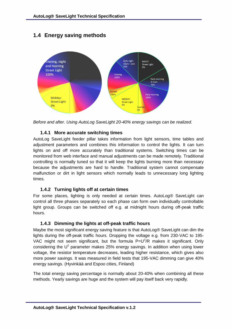
Before and after. Using AutoLog SaveLight 20-40% energy savings can be realized.
1.4.1 More accurate switching times
AutoLog SaveLight feeder pillar takes information from light sensors, time tables and
adjustment parameters and combines this information to control the lights. It can turn
lights on and off more accurately than traditional systems. Switching times can be
monitored from web interface and manual adjustments can be made remotely. Traditional
controlling is normally tuned so that it will keep the lights burning more than necessary
because the adjustments are hard to handle. Traditional system cannot compensate
malfunction or dirt in light sensors which normally leads to unnecessary long lighting
times.
1.4.2 Turning lights off at certain times
For some places, lighting is only needed at certain times. AutoLog® SaveLight can
control all three phases separately so each phase can form own individually controllable
light group. Groups can be switched off e.g. at midnight hours during off-peak traffic
hours.
1.4.3 Dimming the lights at off-peak traffic hours
Maybe the most significant energy saving feature is that AutoLog® SaveLight can dim the
lights during the off-peak traffic hours. Dropping the voltage e.g. from 230-VAC to 195-
VAC might not seem significant, but the formula P=U2/R makes it significant. Only
considering the U2 parameter makes 25% energy savings. In addition when using lower
voltage, the resistor temperature decreases, leading higher resistance, which gives also
more power savings. It was measured in field tests that 195-VAC dimming can give 40%
energy savings. (Hyvinkää and Espoo cities, Finland)
The total energy saving percentage is normally about 20-40% when combining all these
methods. Yearly savings are huge and the system will pay itself back very rapidly.
AutoLog SaveLight Technical Specification 11 (104)
AutoLog SaveLight Technical Specification v.1.2
1.5 Remote Web interface
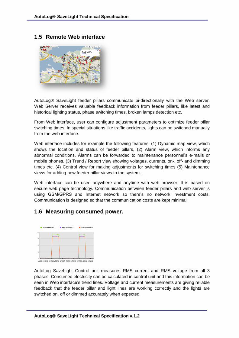
AutoLog® SaveLight feeder pillars communicate bi-directionally with the Web server.
Web Server receives valuable feedback information from feeder pillars, like latest and
historical lighting status, phase switching times, broken lamps detection etc.
From Web interface, user can configure adjustment parameters to optimize feeder pillar
switching times. In special situations like traffic accidents, lights can be switched manually
from the web interface.
Web interface includes for example the following features: (1) Dynamic map view, which
shows the location and status of feeder pillars, (2) Alarm view, which informs any
abnormal conditions. Alarms can be forwarded to maintenance personnel’s e-mails or
mobile phones. (3) Trend / Report view showing voltages, currents, on-, off- and dimming
times etc. (4) Control view for making adjustments for switching times (5) Maintenance
views for adding new feeder pillar views to the system.
Web interface can be used anywhere and anytime with web browser. It is based on
secure web page technology. Communication between feeder pillars and web server is
using GSM/GPRS and Internet network so there’s no network investment costs.
Communication is designed so that the communication costs are kept minimal.
1.6 Measuring consumed power.
AutoLog SaveLight Control unit measures RMS current and RMS voltage from all 3
phases. Consumed electricity can be calculated in control unit and this information can be
seen in Web interface’s trend lines. Voltage and current measurements are giving reliable
feedback that the feeder pillar and light lines are working correctly and the lights are
switched on, off or dimmed accurately when expected.
AutoLog SaveLight Technical Specification 12 (104)
AutoLog SaveLight Technical Specification v.1.2
When lights are broken, it alters the supplied voltage. These changes are automatically
detected in the feeder pillars and “burned lamp” alarm can be send to Web server.
In some areas pilferage (stealing) of electricity can be a problem. Pilferage can be
detected when measured current consumption rises above defined alarm limits.
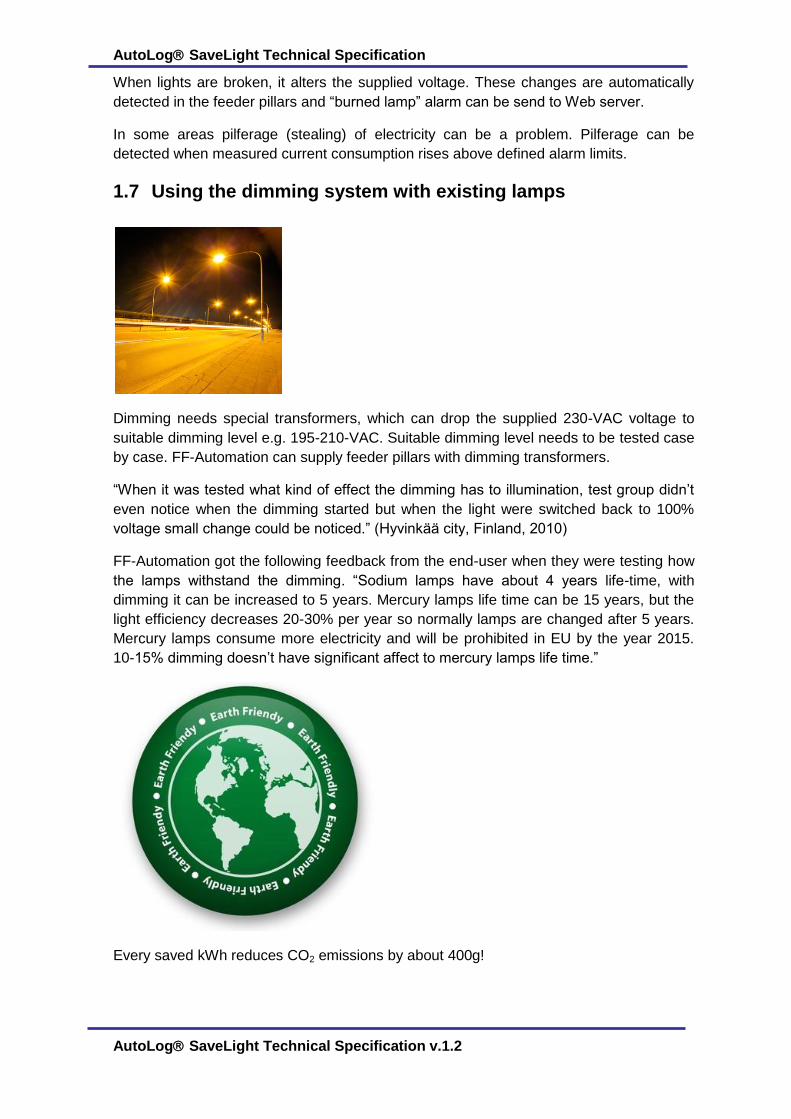
1.7 Using the dimming system with existing lamps
Dimming needs special transformers, which can drop the supplied 230-VAC voltage to
suitable dimming level e.g. 195-210-VAC. Suitable dimming level needs to be tested case
by case. FF-Automation can supply feeder pillars with dimming transformers.
“When it was tested what kind of effect the dimming has to illumination, test group didn’t
even notice when the dimming started but when the light were switched back to 100%
voltage small change could be noticed.” (Hyvinkää city, Finland, 2010)
FF-Automation got the following feedback from the end-user when they were testing how
the lamps withstand the dimming. “Sodium lamps have about 4 years life-time, with
dimming it can be increased to 5 years. Mercury lamps life time can be 15 years, but the
light efficiency decreases 20-30% per year so normally lamps are changed after 5 years.
Mercury lamps consume more electricity and will be prohibited in EU by the year 2015.
10-15% dimming doesn’t have significant affect to mercury lamps life time.”
Every saved kWh reduces CO2 emissions by about 400g!

AutoLog SaveLight Technical Specification 13 (104)
AutoLog SaveLight Technical Specification v.1.2
1.8 GSM connection
As a communication system for AutoLog® SaveLight it was chosen reliable and
widespread GSM (GPRS) network. Being in fact a worldwide standard for mobile
communication, GSM networks are working in the most part of countries and cities. It is
obvious that GSM has lots of advantages.
It is reliable and fault tolerant;
Supported in most countries and cities;
Supports spurious communication sessions;
Does not require own network or additional equipment;
Low-cost communication;
Easy-to-maintain equipment;
AutoLog® SaveLight control unit has built-in GSM modem which is a reliable
communication tool, connected directly to PLC. SIM card (to be provided by customer)
have to support basic functions like SMS and GPRS.
Supplied stubby GSM antenna has to be connected to HF_CON connector. GSM
LED light shows how GSM connection works. If signal is too weak for normal operation
(metal enclosure, long distance from base stations etc.), it is recommended to install
outdoor antenna, connected to HF_CON. Antenna type and its place have to be
determined according to local installation condition. Various types of antennas and cables
can be requested from FF-Automation.
AutoLog SaveLight Technical Specification 14 (104)
AutoLog SaveLight Technical Specification v.1.2
2 Products
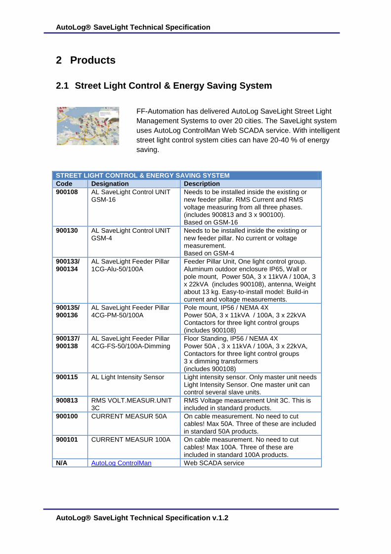
2.1 Street Light Control & Energy Saving System
FF-Automation has delivered AutoLog SaveLight Street Light
Management Systems to over 20 cities. The SaveLight system
uses AutoLog ControlMan Web SCADA service. With intelligent
street light control system cities can have 20-40 % of energy
saving.
STREET LIGHT CONTROL & ENERGY SAVING SYSTEM
Code Designation Description
900108 AL SaveLight Control UNIT GSM-16
Needs to be installed inside the existing or new feeder pillar. RMS Current and RMS voltage measuring from all three phases. (includes 900813 and 3 x 900100). Based on GSM-16
900130 AL SaveLight Control UNIT GSM-4
Needs to be installed inside the existing or new feeder pillar. No current or voltage measurement. Based on GSM-4
900133/ 900134
AL SaveLight Feeder Pillar 1CG-Alu-50/100A
Feeder Pillar Unit, One light control group. Aluminum outdoor enclosure IP65, Wall or pole mount, Power 50A, 3 x 11kVA / 100A, 3 x 22kVA (includes 900108), antenna, Weight about 13 kg. Easy-to-install model: Build-in current and voltage measurements.
900135/ 900136
AL SaveLight Feeder Pillar 4CG-PM-50/100A
Pole mount, IP56 / NEMA 4X Power 50A, 3 x 11kVA / 100A, 3 x 22kVA Contactors for three light control groups (includes 900108)
900137/ 900138
AL SaveLight Feeder Pillar 4CG-FS-50/100A-Dimming
Floor Standing, IP56 / NEMA 4X Power 50A , 3 x 11kVA / 100A, 3 x 22kVA, Contactors for three light control groups 3 x dimming transformers (includes 900108)
900115 AL Light Intensity Sensor Light intensity sensor. Only master unit needs Light Intensity Sensor. One master unit can control several slave units.
900813 RMS VOLT.MEASUR.UNIT 3C
RMS Voltage measurement Unit 3C. This is included in standard products.
900100 CURRENT MEASUR 50A On cable measurement. No need to cut cables! Max 50A. Three of these are included in standard 50A products.
900101 CURRENT MEASUR 100A On cable measurement. No need to cut cables! Max 100A. Three of these are included in standard 100A products.
N/A AutoLog ControlMan Web SCADA service
AutoLog SaveLight Technical Specification 15 (104)
AutoLog SaveLight Technical Specification v.1.2
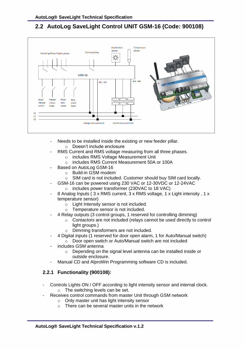
2.2 AutoLog SaveLight Control UNIT GSM-16 (Code: 900108)
- Needs to be installed inside the existing or new feeder pillar.
o Doesn’t include enclosure - RMS Current and RMS voltage measuring from all three phases.
o includes RMS Voltage Measurement Unit o includes RMS Current Measurement 50A or 100A
- Based on AutoLog GSM-16 o Build-in GSM modem o SIM card is not included. Customer should buy SIM card locally.
- GSM-16 can be powered using 230 VAC or 12-30VDC or 12-24VAC o includes power transformer (230VAC to 18 VAC)
- 8 Analog Inputs ( 3 x RMS current, 3 x RMS voltage, 1 x Light intensity , 1 x temperature sensor)
o Light Intensity sensor is not included. o Temperature sensor is not included.
- 4 Relay outputs (3 control groups, 1 reserved for controlling dimming) o Contactors are not included (relays cannot be used directly to control
light groups.) o Dimming transformers are not included.
- 4 Digital inputs (1 reserved for door open alarm, 1 for Auto/Manual switch) o Door open switch or Auto/Manual switch are not included
- includes GSM antenna o Depending on the signal level antenna can be installed inside or
outside enclosure. - Manual CD and AlproWin Programming software CD is included.
2.2.1 Functionality (900108):
- Controls Lights ON / OFF according to light intensity sensor and internal clock. o The switching levels can be set.
- Receives control commands from master Unit through GSM network o Only master unit has light intensity sensor o There can be several master units in the network

AutoLog SaveLight Technical Specification 16 (104)
AutoLog SaveLight Technical Specification v.1.2
o Master unit can control several slave units to switch ON/OFF the lights using free GSM call controlling.
o Unit can operate as slave or master unit. Selection can be made using jumper cable.
- Can turn OFF the lights in the midnight at off-peak traffic hours. - Measures RMS voltage and RMS current to detect any failure and to get feedback
that the lights are turned on / off. o Algorithm detects burned lamps.
- Sends measurement and status information to ControlMan Web service o GSM-16 can log measurement data into its memory o Data can be send using SMS or GPRS/FTP
2.3 AutoLog SaveLight Control UNIT GSM-4 (Code 900130)
- Needs to be installed inside the existing or new feeder pillar. o Doesn’t include enclosure
- Based on AutoLog GSM-4 o Build-in GSM modem o SIM card is not included. Customer should buy SIM card locally.
- GSM-4 can be powered using 230 VAC or 12-30VDC or 12-24VAC o includes power transformer (230VAC to 18 VAC)
- No Analog Inputs o No current or voltage measurements.(Broken lamps cannot be
detected, Street light line power interruptions cannot be detected.) o No light sensor (Unit cannot operate as master unit)
- 2 Relay outputs (2 control groups or 1 control group and 1 reserved for controlling dimming)
o Contactors are not included (relays cannot be used directly to control light groups.)
o Dimming transformers are not included. If you use dimming, GSM-16 is suggested to get feedback from voltages and current levels.
- 4 Digital inputs (1 reserved for door open alarm, 1 for Auto/Manual switch) o Door open switch or Auto/Manual switch are not included
- includes GSM antenna

AutoLog SaveLight Technical Specification 17 (104)
AutoLog SaveLight Technical Specification v.1.2
o Depending on the signal level antenna can be installed inside or outside enclosure.
- Manual CD and AlproWin Programming software CD is included.
2.3.1 Functionality (900130):
- Controls Lights ON / OFF according to light intensity sensor and internal clock. o The switching levels can be set. o Allows max. 2 control groups. Normally only one control group is used.
- Receives control commands from Master Unit through GSM network o Unit can operate only as slave unit. Master unit need to be GSM-16.
- Can turn OFF the lights in the midnight at off-peak traffic hours. - Sends status information to ControlMan Web service
o GSM-4 can log status data into its memory o Data can be send using SMS or GPRS/FTP
AutoLog SaveLight Technical Specification 18 (104)
AutoLog SaveLight Technical Specification v.1.2
o
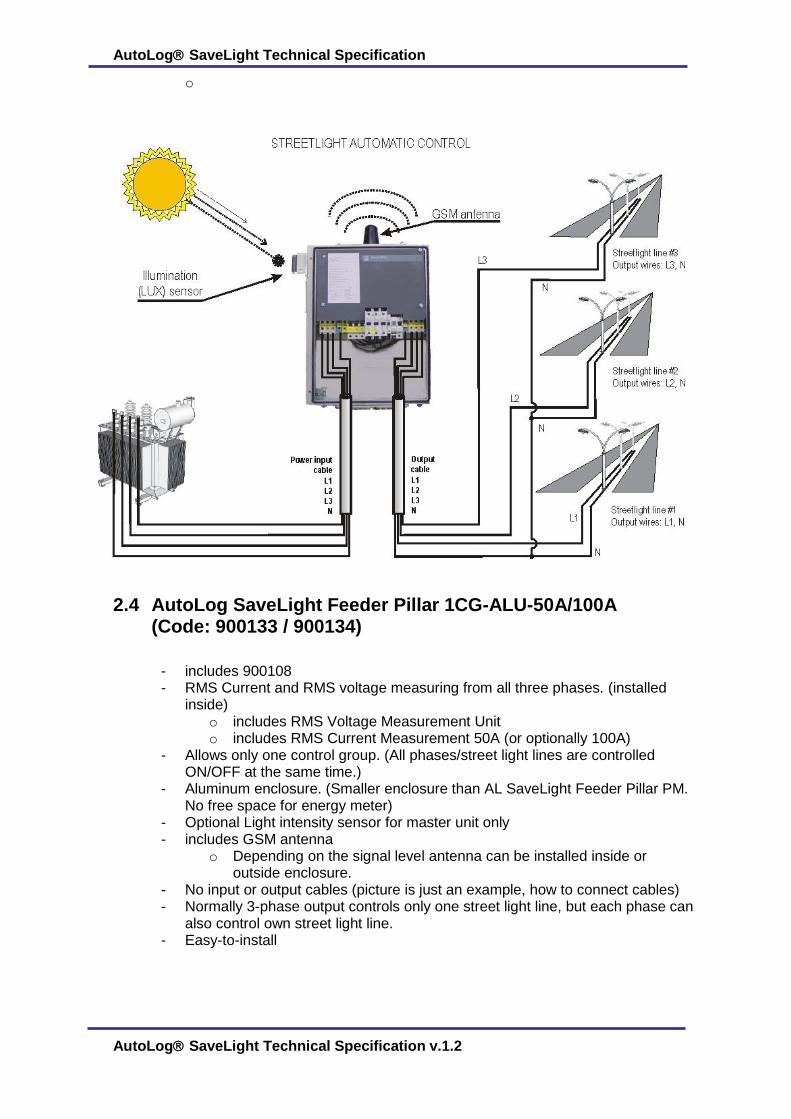
2.4 AutoLog SaveLight Feeder Pillar 1CG-ALU-50A/100A (Code: 900133 / 900134)
- includes 900108 - RMS Current and RMS voltage measuring from all three phases. (installed
inside) o includes RMS Voltage Measurement Unit o includes RMS Current Measurement 50A (or optionally 100A)
- Allows only one control group. (All phases/street light lines are controlled ON/OFF at the same time.)
- Aluminum enclosure. (Smaller enclosure than AL SaveLight Feeder Pillar PM. No free space for energy meter)
- Optional Light intensity sensor for master unit only - includes GSM antenna
o Depending on the signal level antenna can be installed inside or outside enclosure.
- No input or output cables (picture is just an example, how to connect cables) - Normally 3-phase output controls only one street light line, but each phase can
also control own street light line. - Easy-to-install
AutoLog SaveLight Technical Specification 19 (104)
AutoLog SaveLight Technical Specification v.1.2
2.4.1 Functionality: AL SaveLight Feeder Pillar 1CG-ALU-50/100A
Same as 900108, but device is equipped to control only one light control group.
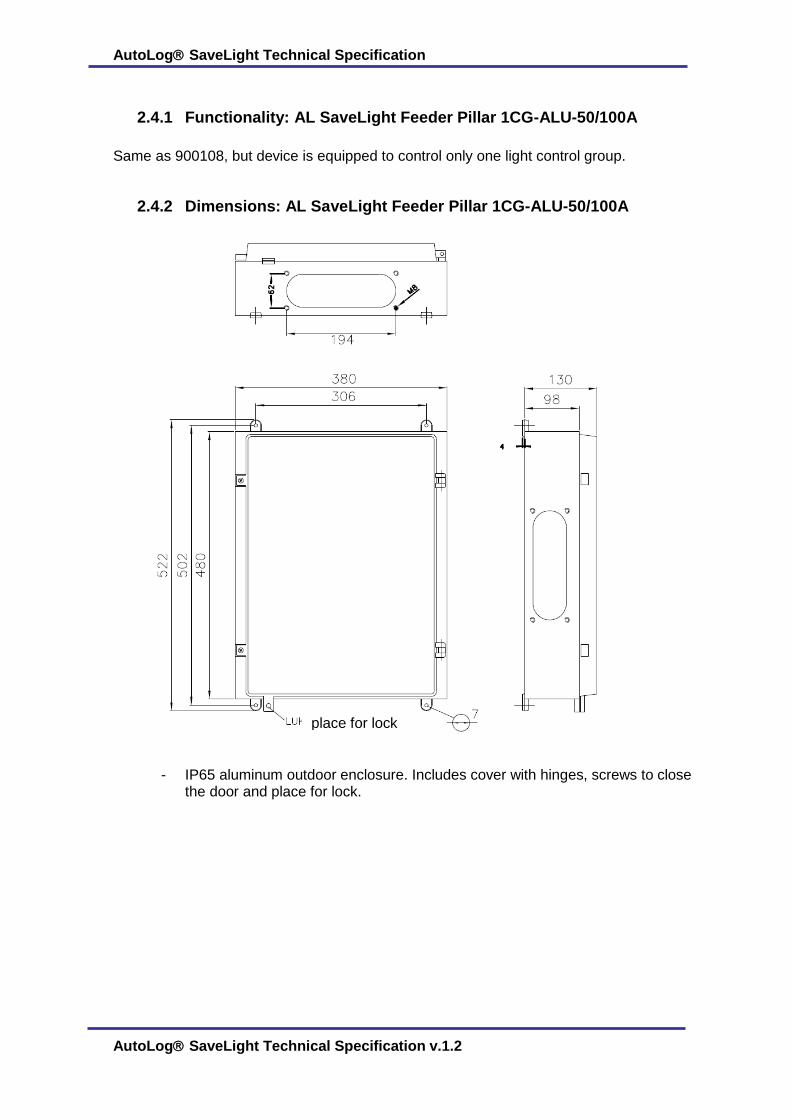
2.4.2 Dimensions: AL SaveLight Feeder Pillar 1CG-ALU-50/100A
- IP65 aluminum outdoor enclosure. Includes cover with hinges, screws to close the door and place for lock.
place for lock

AutoLog SaveLight Technical Specification 20 (104)
AutoLog SaveLight Technical Specification v.1.2
2.5 AL SaveLight Feeder Pillar 4CG-PM-50A/100A (Pole Mount) (Code: 900135 / 900136)
- Order code: 900135: 50A / 3 x 11kVA - Order code: 900136: 100A / 3 x 22kVA - Pole not included - No dimming transformers
- includes 900108 - free space for energy meter - 4 control groups equipped with separate contactors - RMS Current and RMS voltage measuring from all three phases
o includes RMS Voltage Measurement Unit o includes RMS Current Measurement 50A (or optionally 100A) (External
installation) - IP56 outdoor enclosure - Optional Light intensity sensor for master unit only - includes GSM antenna
o Depending on the signal level antenna can be installed inside or outside enclosure.

AutoLog SaveLight Technical Specification 21 (104)
AutoLog SaveLight Technical Specification v.1.2
2.6 AL SaveLight Feeder Pillar 4CG-FS-50A/100A-Dimming (Floor Standing) (Code: 900137 / 900138)
- Order code: 900137: 50A / 3 x 11kVA - Order code: 900138: 100A / 3 x 22kVA - Includes Dimming Transformers for all 3 phases
- includes 900108 - free space for energy meter - 4 control groups equipped with separate contactors - RMS Current and RMS voltage measuring from all three phases
o includes RMS Voltage Measurement Unit o includes RMS Current Measurement 50A (or optionally 100A) (External
installation) - IP56 outdoor enclosure - Optional Light intensity sensor for master unit only - includes GSM antenna
o Depending on the signal level antenna can be installed inside or outside enclosure.

AutoLog SaveLight Technical Specification 22 (104)
AutoLog SaveLight Technical Specification v.1.2
3 Contact details
Would you have any questions, requests or you need any help or assistance, please
contact us. Our specialists, who have developed and produced all our equipment will give
you all needed information and advises.
3.1 Head Office :
FF-Automation Oy Eräkuja 2 01600 Vantaa Finland Tel: +358 10 2190 500 Fax: +358 3 5846 711 [email protected]
3.2 Factory:
FF-Automation Oy Meijerikuja 37600 Valkeakoski Finland Tel: +358 10 2190 500 Fax: +358 3 5846 711 [email protected]