scaleup and commercialization of warm syngas cleanup technology
TRANSCRIPT
Center for Energy Technology
Scaleup and Commercialization of Warm Syngas Cleanup Technology with Carbon Capture and StorageTechnology with Carbon Capture and Storage
2010 Gasification Technology Conference, Washington, D.C.
Raghubir Gupta, Aqil Jamal, Brian Turk, and Markus Lesemann
Center for Energy TechnologyRTI International
Research Triangle Park, NC
RTI International is a trade name of Research Triangle Institute.
www.rti.org

Center for Energy Technology
RTI InternationalRTI International
Established 1958 as collaboration between state government, area universities and business leadersuniversities and business leadersMission: to improve the human condition by turning knowledge into practiceOne of the world’s leading research institutes FY2009 Research revenue: $717.9 million$Staff : 2,866
2
Center for Energy Technology
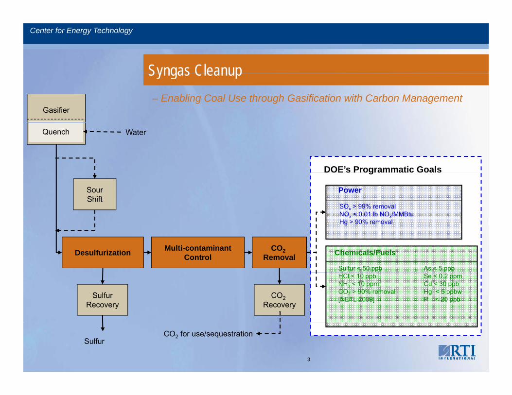
Syngas CleanupSyngas Cleanup– Enabling Coal Use through Gasification with Carbon Management
Gasifier
Quench Water
DOE’s Programmatic Goals
PowerSourShift
SOx > 99% removalNOx < 0.01 lb NOx/MMBtuHg > 90% removal
g
Sulfur < 50 ppb As < 5 ppb
Desulfurization CO2Removal Chemicals/Fuels
Hg > 90% removal
Multi-contaminantControl
HCl < 10 ppbNH3 < 10 ppmCO2 > 90% removal[NETL 2009]
Se < 0.2 ppmCd < 30 ppbHg < 5 ppbwP < 20 ppbCO2
RecoverySulfur
Recovery
CO2 for use/sequestrationSulfur
3
Center for Energy Technology
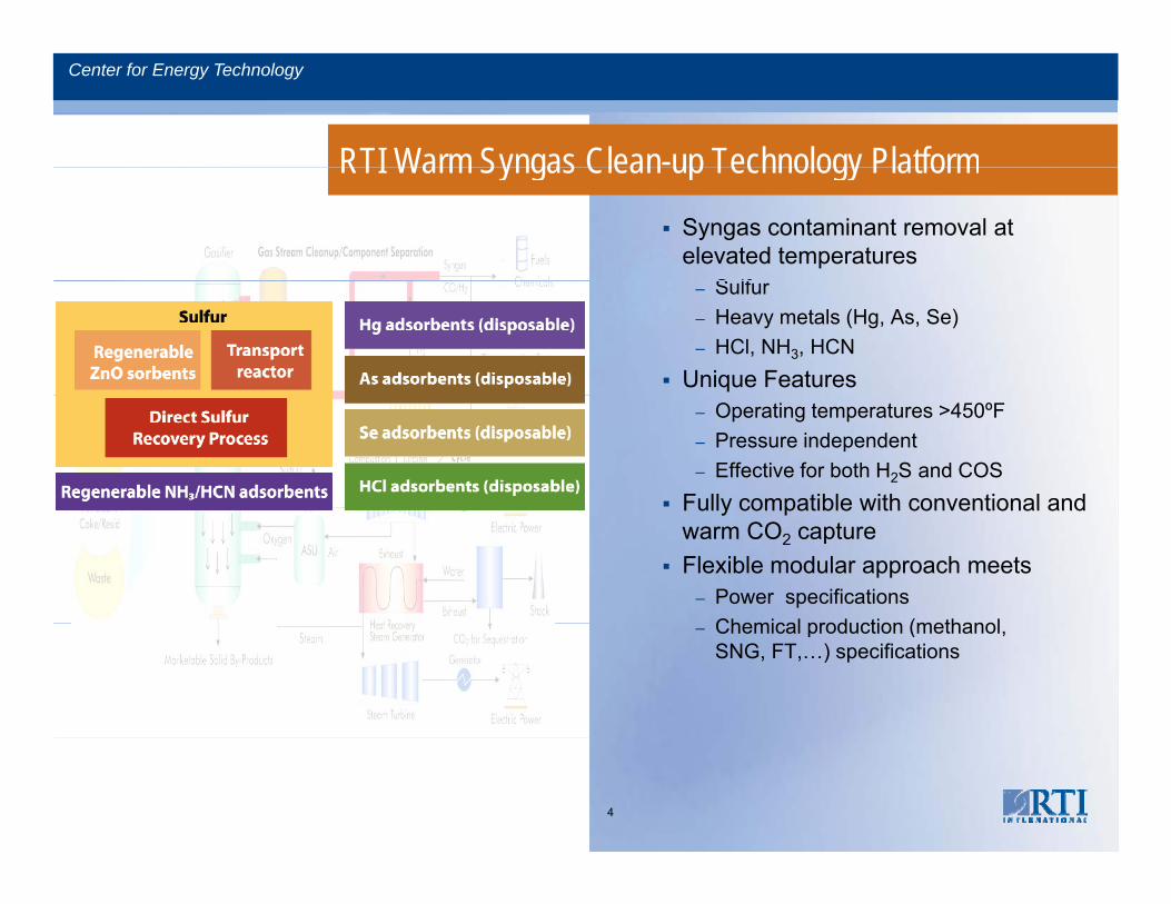
RTI Warm Syngas Clean-up Technology PlatformRTI Warm Syngas Clean up Technology Platform
Syngas contaminant removal at elevated temperatures
S lf– Sulfur– Heavy metals (Hg, As, Se)– HCl, NH3, HCN
Unique Features– Operating temperatures >450ºF – Pressure independent– Effective for both H2S and COS
Fully compatible with conventional andFully compatible with conventional and warm CO2 captureFlexible modular approach meets
– Power specificationsChemical production (methanol– Chemical production (methanol, SNG, FT,…) specifications
4
Center for Energy Technology
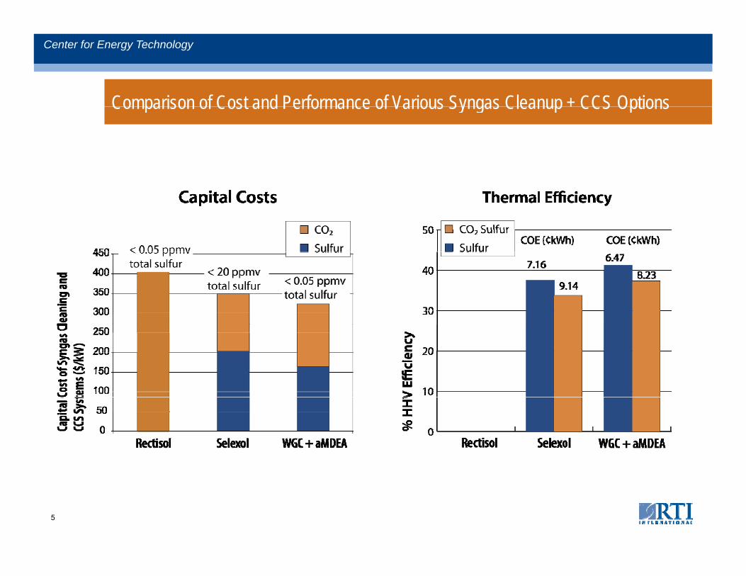
Comparison of Cost and Performance of Various Syngas Cleanup + CCS Options
Center for Energy Technology
Comparison of Cost and Performance of Various Syngas Cleanup + CCS Options
5
Center for Energy Technology
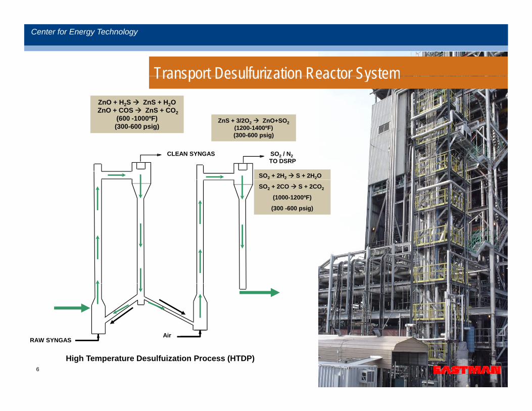
Transport Desulfurization Reactor SystemTransport Desulfurization Reactor SystemZnO + H2S ZnS + H2OZnO + COS ZnS + CO2
(600 -1000ºF)(300-600 psig)
ZnS + 3/2O2 ZnO+SO2(1200 1400ºF)(300 600 psig)
CLEAN SYNGAS SO2 / N2TO DSRP
(1200-1400 F)(300-600 psig)
SO2 + 2H2 S + 2H2O
SO2 + 2CO S + 2CO2
(1000-1200ºF)
(300 -600 psig)
AirRAW SYNGAS
Air
High Temperature Desulfuization Process (HTDP)6
Center for Energy Technology
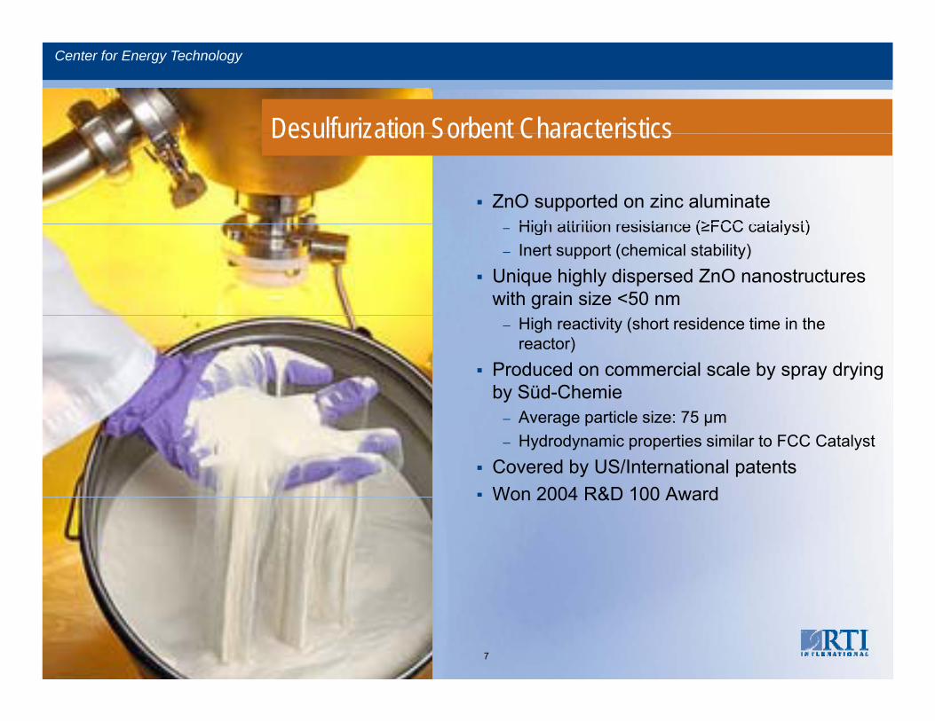
Desulfurization Sorbent CharacteristicsDesulfurization Sorbent Characteristics
ZnO supported on zinc aluminateHigh attrition resistance (≥FCC catalyst)– High attrition resistance (≥FCC catalyst)
– Inert support (chemical stability)Unique highly dispersed ZnO nanostructures with grain size <50 nm
– High reactivity (short residence time in the reactor)
Produced on commercial scale by spray drying by Süd-Chemie
– Average particle size: 75 μm– Hydrodynamic properties similar to FCC Catalyst
Covered by US/International patentsWon 2004 R&D 100 AwardWon 2004 R&D 100 Award
7
Center for Energy Technology
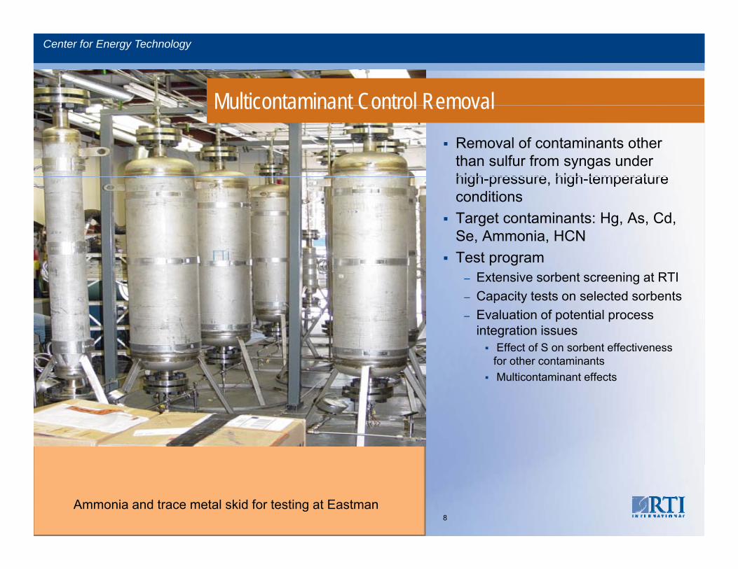
Multicontaminant Control RemovalMulticontaminant Control Removal
Removal of contaminants other than sulfur from syngas under high pressure high temperaturehigh-pressure, high-temperature conditionsTarget contaminants: Hg, As, Cd, Se, Ammonia, HCNTest program
– Extensive sorbent screening at RTI– Capacity tests on selected sorbents– Evaluation of potential process p p
integration issues Effect of S on sorbent effectiveness for other contaminants Multicontaminant effects
Ammonia and trace metal skid for testing at Eastman8
Center for Energy Technology
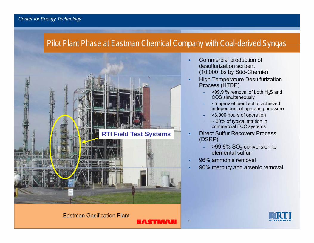
Pilot Plant Phase at Eastman Chemical Company with Coal-derived SyngasPilot Plant Phase at Eastman Chemical Company with Coal derived Syngas
Commercial production of desulfurization sorbent (10,000 lbs by Süd-Chemie)High Temperature Desulfurization Process (HTDP)
– >99.9 % removal of both H2S and COS simultaneously
– <5 ppmv effluent sulfur achieved independent of operating pressure
– >3,000 hours of operation– ~ 60% of typical attrition in
commercial FCC systems Direct Sulfur Recovery Process RTI Field Test Systems(DSRP)
– >99.8% SO2 conversion to elemental sulfur
96% ammonia removal90% mercury and arsenic removal
y
90% mercury and arsenic removal
Eastman Gasification Plant9
Center for Energy Technology
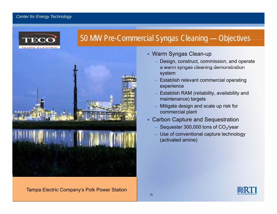
50 MW Pre-Commercial Syngas Cleaning — Objectives50 MW Pre Commercial Syngas Cleaning Objectives
Warm Syngas Clean-up– Design, construct, commission, and operate
a warm syngas cleaning demonstrationa warm syngas cleaning demonstration system
– Establish relevant commercial operating experience
– Establish RAM (reliability availability and– Establish RAM (reliability, availability and maintenance) targets
– Mitigate design and scale up risk for commercial plant
Carbon Capture and SequestrationCarbon Capture and Sequestration– Sequester 300,000 tons of CO2/year– Use of conventional capture technology
(activated amine)
10Tampa Electric Company’s Polk Power Station
Center for Energy Technology
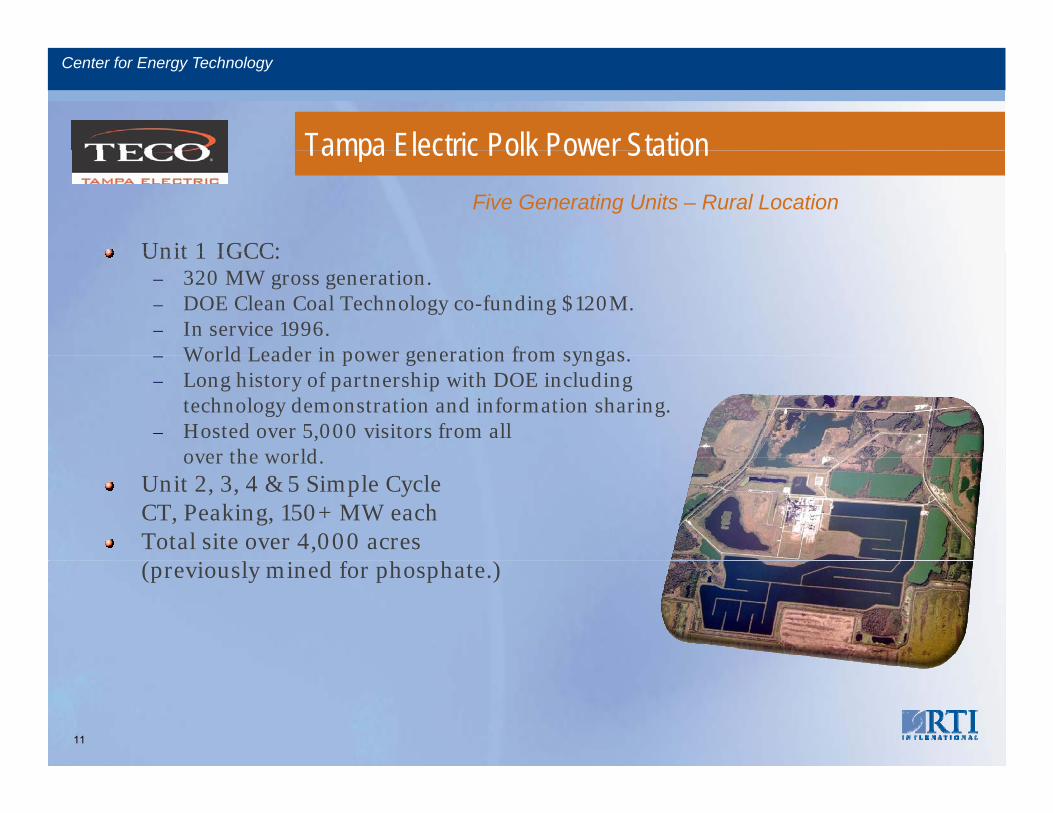
Tampa Electric Polk Power Station
Unit 1 IGCC:
Tampa Electric Polk Power StationFive Generating Units – Rural Location
Unit 1 IGCC:– 320 MW gross generation.– DOE Clean Coal Technology co-funding $120M.– In service 1996.
World Leader in power generation from syngas– World Leader in power generation from syngas.– Long history of partnership with DOE including
technology demonstration and information sharing.– Hosted over 5,000 visitors from all
over the worldover the world.Unit 2, 3, 4 & 5 Simple Cycle CT, Peaking, 150+ MW eachTotal site over 4,000 acres ( i l i d f h h )(previously mined for phosphate.)
11
Center for Energy Technology
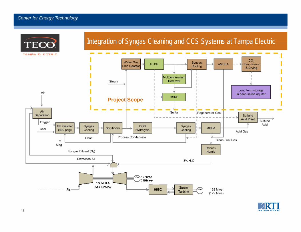
Integration of Syngas Cleaning and CCS Systems at Tampa Electric
Center for Energy Technology
Integration of Syngas Cleaning and CCS Systems at Tampa Electric
Water GasShift Reactor HTDP Syngas
CoolingaMDEA
CO2Compression
& Drying
Air
SteamMultcontaminant
Removal
DSRP
Long term storagein deep saline aquifer
Project Scope
AirSeparation
GE Gasifier(400 psig)
SyngasCooling Scrubbers COS
Hydrolysis
Oxygen
CoalSyngasCooling MDEA
SulfuricAcid Plant Sulfuric
Acid
A id G
Sulfur Regenerator Gas
oject Scope
(400 psig) Cooling Hydrolysis
Char
Cooling
Process Condensate
Reheat/Humid
Clean Fuel GasSlag
Acid Gas
Syngas Diluent (N2)
8% H OExtraction Air
128 Mwe
8% H2Oac o
~
~Raw Syngas 128 Mwe(122 Mwe)
~
12
CleanFuel Gas
Process Water
Raw Syngas
Center for Energy Technology
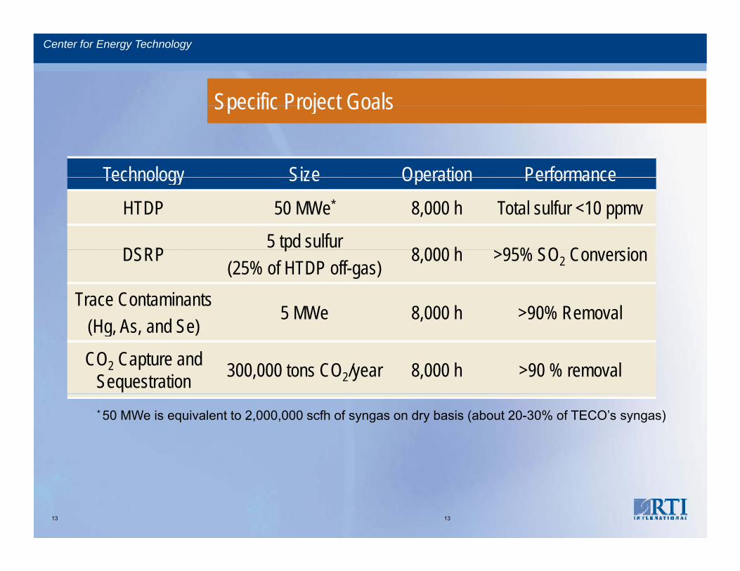
Specific Project Goals
Center for Energy Technology
Specific Project Goals
Technology Size Operation PerformanceTechnology Size Operation PerformanceHTDP 50 MWe* 8,000 h Total sulfur <10 ppmv
DSRP5 tpd sulfur
8 000 h 95% SO C iDSRPp
(25% of HTDP off-gas)8,000 h >95% SO2 Conversion
Trace Contaminants(H A d S )
5 MWe 8,000 h >90% Removal(Hg, As, and Se)
,
CO2 Capture and Sequestration 300,000 tons CO2/year 8,000 h >90 % removal
* 50 MWe is equivalent to 2,000,000 scfh of syngas on dry basis (about 20-30% of TECO’s syngas)
13 13
Center for Energy Technology
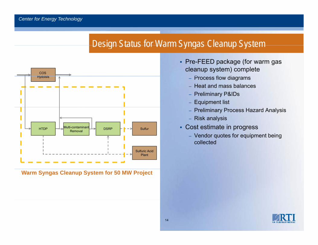
Design Status for Warm Syngas Cleanup SystemDesign Status for Warm Syngas Cleanup System
Pre-FEED package (for warm gas cleanup system) complete
P fl diCOS
H dolsis – Process flow diagrams– Heat and mass balances – Preliminary P&IDs– Equipment list
Hydolsis
– Preliminary Process Hazard Analysis – Risk analysis
Cost estimate in progress– Vendor quotes for equipment being
HTDP Multi-contaminantRemoval
DSRP Sulfur
q q p gcollected
Sulfuric AcidPlant
Warm Syngas Cleanup System for 50 MW Project
14
Center for Energy Technology
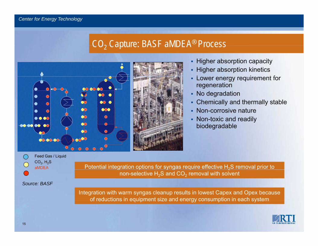
CO2 Capture: BASF aMDEA® ProcessCO2 Capture: BASF aMDEA ProcessHigher absorption capacity Higher absorption kineticsL i t fLower energy requirement for regeneration No degradationChemically and thermally stableNon-corrosive nature Non-toxic and readily biodegradable
Feed Gas / LiquidCO2, H2SaMDEA Potential integration options for syngas require effective H2S removal prior to
Source: BASF
Integration with warm syngas cleanup results in lowest Capex and Opex because of reductions in equipment size and energy consumption in each system
g p y g q 2 pnon-selective H2S and CO2 removal with solvent
of reductions in equipment size and energy consumption in each system
15
Center for Energy Technology
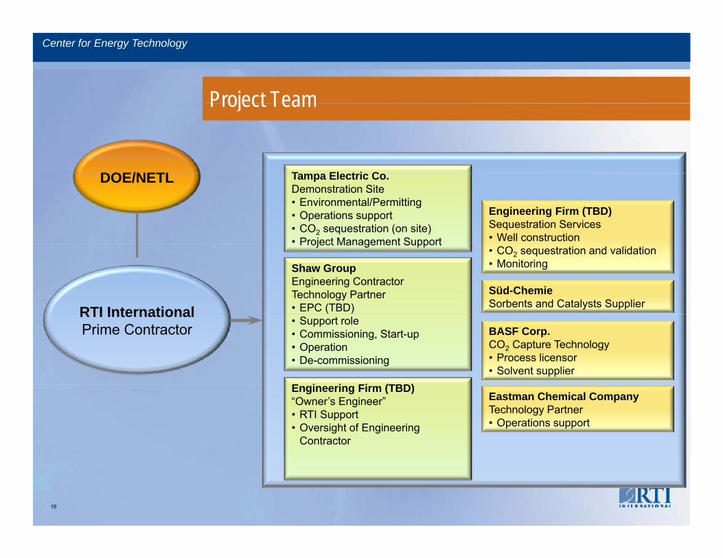
Project TeamProject Team
T El t i CDOE/NETL Tampa Electric Co.Demonstration Site• Environmental/Permitting• Operations support• CO2 sequestration (on site)• Project Management Support
Engineering Firm (TBD)Sequestration Services• Well construction
DOE/NETL
Shaw GroupEngineering ContractorTechnology Partner• EPC (TBD)
Project Management Support• CO2 sequestration and validation• Monitoring
Süd-ChemieSorbents and Catalysts SupplierRTI International
• Support role• Commissioning, Start-up• Operation• De-commissioning
BASF Corp.CO2 Capture Technology• Process licensor• Solvent supplier
E i i Fi (TBD)
RTI InternationalPrime Contractor
Eastman Chemical CompanyTechnology Partner• Operations support
Engineering Firm (TBD)“Owner’s Engineer”• RTI Support• Oversight of Engineering
Contractor
16
Center for Energy Technology
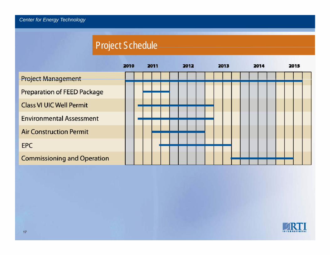
Project ScheduleProject Schedule
17
Center for Energy Technology
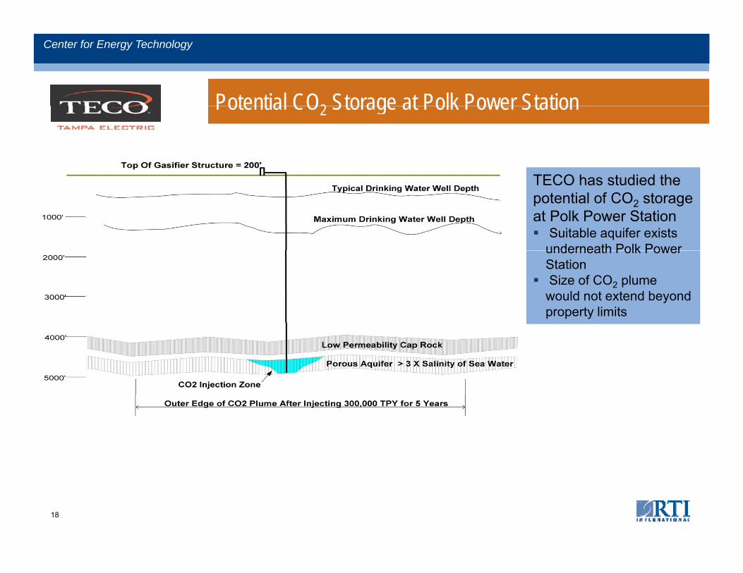
Potential CO2 Storage at Polk Power StationPotential CO2 Storage at Polk Power Station
TECO has studied theTECO has studied the potential of CO2 storage at Polk Power Station
Suitable aquifer exists underneath Polk Powerunderneath Polk Power StationSize of CO2 plume would not extend beyond property limits
18
Center for Energy Technology
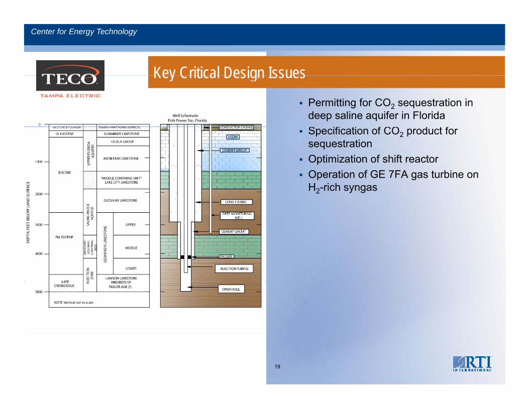
Key Critical Design IssuesKey Critical Design Issues
Permitting for CO2 sequestration in deep saline aquifer in FloridaS ifi ti f CO d t fSpecification of CO2 product for sequestrationOptimization of shift reactorOperation of GE 7FA gas turbine on p gH2-rich syngas
19
Center for Energy Technology
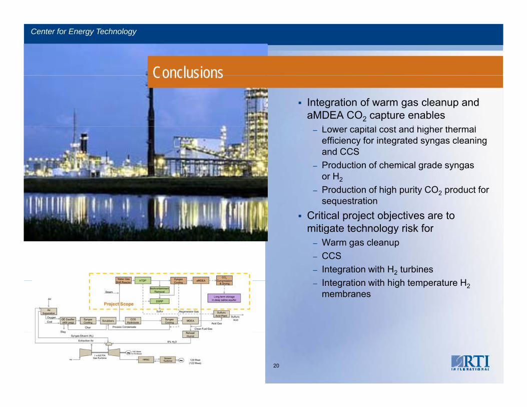
ConclusionsConclusions
Integration of warm gas cleanup and aMDEA CO2 capture enables
L it l t d hi h th l– Lower capital cost and higher thermal efficiency for integrated syngas cleaning and CCS
– Production of chemical grade syngasor H2or H2
– Production of high purity CO2 product for sequestration
Critical project objectives are to mitigate technology risk formitigate technology risk for
– Warm gas cleanup– CCS– Integration with H2 turbines
I t ti ith hi h t t H– Integration with high temperature H2membranes
20

Center for Energy Technology
AcknowledgementsAcknowledgements
Funding provided by DOE/NETLDOE/NETL Technical Team
– Jenny Tenant– Gary Stiegel– David Lyons– Kanwal Mahajan– Sam Tam– Pete Rozelle
Tampa ElectricShawShawBASFEastman ChemicalSüd Chemie Inc.
21