schirmung und erdung earthing and shielding - r. stahl · schirmung und erdung earthing and...
TRANSCRIPT

Schirmung und Erdung
Earthing and shielding
IS1+ Remote IO System
IS1+ Remote IO System
DE Handbuch Manual
Additional languages wwwr-stahlcom
EN
2 Erdung und Schirmung IS1+ Remote IO 2017-07-25HB00IIIdeen
Schirmung und Erdung
IS1+ Remote IO System
DE Handbuch
Additional languages wwwr-stahlcom
2 Erdung und Schirmung IS1+ Remote IO 2017-07-25HB00IIIde
Inhaltsverzeichnis
1 Allgemeine Angaben 3
11 Hersteller 3
12 Angaben zur Betriebsanleitung 3
13 Weitere Dokumente 3
14 Konformitaumlt zur Norm und Bestimmungen 3
2 Erlaumluterung der Symbole 4
21 Symbole in der Betriebsanleitung 4
22 Warnhinweise 4
3 Allgemeine Sicherheitshinweise 4
31 Sicherheitshinweise fuumlr das Projektierungspersonal 4
32 Anwendbare Standards 5
33 Anzuwendende Standards fuumlr Betreiber 5
4 Auswahl des Feldgehaumluses 6
5 Empfohlene Installation von Komponenten und Betriebsmittel im Feldgehaumluse 7
51 Im Metallgehaumluse 7
511 Empfohlene Installation 7
512 Alternative Installation 9
52 Im Kunststoffgehaumluse 10
521 Empfohlene Installation 10
522 Alternative Installation 12
53 Anordnung von Betriebsmitteln mit Hilfsenergieanschluss 13
54 Anordnung von Fremdprodukten 13
6 Anschluss von Feldkabeln und Feldbuskabeln an Schirmung 13
61 Empfohlene Schirmauflage 13
62 Alternative Schirmauflage 14
63 Alternative Schirmauflage ndash nicht empfohlen 14
7 Bauseitiger Potentialausgleich 15
71 Netzform 15
72 Anforderungen an das Erdnetz des Explosionsgefaumlhrdeten Bereichs 16
73 Anschlieszligen der Feldstation an den Potentialausgleich der Anlage 16
8 Verlegen von Feldkabeln Feldbuskabeln und Versorgungsleitungen im Feld 16
81 Allgemeine Anforderung an die Verlegung 17
Erdung und Schirmung 3 2017-07-25HB00IIIde IS1+ Remote IO
1 Allgemeine Angaben
11 Hersteller R STAHL Schaltgeraumlte GmbH Am Bahnhof 30 74638 Waldenburg Germany Tel +49 7942 943-0 Fax +49 7942 943-4333 Internet wwwr-stahlcom E-Mail infostahlde
12 Angaben zur Betriebsanleitung Publikationsnummer 2017-07-25HB00IIIde01 Die Originalbetriebsanleitung ist die deutsche Ausgabe Diese ist rechtsverbindlich in allen juristischen Angelegenheiten
13 Weitere Dokumente
Kopplungsbeschreibung IS1 (Download unter wwwr-stahlcom)
Betriebsanleitungen IS1+ Dokumente in weitere Sprachen siehe wwwr-stahlcom
14 Konformitaumlt zur Norm und Bestimmungen Siehe Zertifikate und EG-Konformitaumltserklaumlrung wwwr-stahlcom Die Geraumlte verfuumlgt uumlber eine IECEx-Zulassung Siehe IECEx-Homepage httpiecexiecch Weitere nationale Zertifikate stehen unter dem folgenden Link zum Download bereit httpsr-stahlcomdeglobalproduktesupportdownloads
4 Erdung und Schirmung IS1+ Remote IO 2017-07-25HB00IIIde
2 Erlaumluterung der Symbole
21 Symbole in der Betriebsanleitung
Symbol Bedeutung
Tipps und Empfehlungen zum Gebrauch des Geraumltes
Gefahr durch explosionsfaumlhige Atmosphaumlre
22 Warnhinweise Warnhinweise unbedingt befolgen um das konstruktive und durch den Betrieb bedingte Risiko zu minimieren Die Warnhinweise sind wie folgt aufgebaut
Signalwort GEFAHR WARNUNG VORSICHT HINWEIS
Art und Quelle der Gefahrdes Schadens
Folgen der Gefahr
Ergreifen von Gegenmaszlignahmen zum Vermeiden der Gefahr bzw des Schadens
GEFAHR Gefahren fuumlr Personen Nichtbeachtung der Anweisung fuumlhrt zu schweren oder toumldlichen Verletzungen bei Personen
WARNUNG Gefahren fuumlr Personen Nichtbeachtung der Anweisung kann zu schweren oder toumldlichen Verletzungen bei Personen fuumlhren
VORSICHT
Gefahren fuumlr Personen Nichtbeachtung der Anweisung kann zu leichten Verletzungen bei Personen fuumlhren
HINWEIS
Vermeidung von Sachschaden Nichtbeachtung der Anweisung kann zu einem Sachschaden am Geraumlt undoder seiner Umgebung fuumlhren
3 Allgemeine Sicherheitshinweise
31 Sicherheitshinweise fuumlr das Projektierungspersonal In diesem Kapitel sind die wichtigsten Sicherheitsmaszlignahmen zusammengefasst Es ergaumlnzt die entsprechenden Vorschriften zu deren Studium das verantwortliche Personal verpflichtet ist Bei Projektierung von Anlagen in explosionsgefaumlhrdeten Bereichen haumlngt die Sicherheit von Personen und Anlagen von der Einhaltung aller relevanten Sicherheitsvorschriften ab Das Projektierungspersonal traumlgt deshalb eine besondere Verantwortung
Erdung und Schirmung 5 2017-07-25HB00IIIde IS1+ Remote IO
Voraussetzung fuumlr die Projektierung ist die genaue Kenntnis der geltenden Vorschriften und Bestimmungen
die nationalen Sicherheits- Unfallverhuumltungs- Montage- und Errichtungsvorschriften (zB IECEN 60079-14)
die allgemein anerkannten Regeln der Technik
die Sicherheitshinweise und Angaben dieses Dokuments
32 Anwendbare Standards
DIN VDE 0100-410 (IEC 60364-4-41 modifiziert) Errichten von Niederspannungsanlagen - Teil 4-41 Schutzmaszlignahmen - Schutz gegen elektrischen Schlag
DIN VDE 0100-443 (IEC 60364-4-44 + A1 modifiziert) Errichten von Niederspannungsanlagen - Teil 4-44 Schutzmaszlignahmen - Schutz bei Stoumlrspannungen und elektromagnetischen Stoumlrgroumlszligen - Abschnitt 443 Schutz bei Uumlberspannungen infolge atmosphaumlrischer Einfluumlsse oder von Schaltvorgaumlngen
DIN VDE 0100-444 (IEC 60364-4-4441996 modifiziert) Elektrische Anlagen von Gebaumluden - Teil 4 Schutzmaszlignahmen - Kapitel 44 Schutz bei Uumlberspannungen Hauptabschnitt 444 Schutz gegen elektromagnetische Stoumlrungen (EMI) in Anlagen von Gebaumluden
DIN VDE 0100-540 (IEC 60364-5-54 modifiziert) Errichten von Niederspannungsanlagen - Teil 5-54 Auswahl und Errichtung elektrischer Betriebsmittel - Erdungsanlagen Schutzleiter und Schutzpotentialausgleichsleiter
33 Anzuwendende Standards fuumlr Betreiber
DIN EN 60079-0 bzw VDE 0170-1 (IEC 60079-0) Explosionsgefaumlhrdete Bereiche - Teil 0 Betriebsmittel - Allgemeine Anforderungen Diese Norm enthaumllt die allgemeinen Anforderungen an die Konstruktion Pruumlfung und Kennzeichnung von elektrischen Geraumlten und Ex-Bauteilen fest die fuumlr die Verwendung in explosionsgefaumlhrdeten Bereichen bestimmt sind
DIN EN 60079-17 bzw VDE 0165-10-1 (IEC 60079-17) Explosionsgefaumlhrdete Bereiche - Teil 17 Pruumlfung und Instandhaltung elektrischer Anlagen Diese Norm gilt fuumlr Betreiber und behandelt nur die Gesichtspunkte die direkt auf die Pruumlfung Wartung und Instandsetzung von elektrischen Anlagen bezogen sind die in explosionsgefaumlhrdeten Bereichen installiert sind
DIN EN 60079-14 bzw VDE 0165-1 (IEC 60079-14) Explosionsfaumlhige Atmosphaumlre - Teil 14 Projektierung Auswahl und Errichtung elektrischer Anlagen Diese Norm enthaumllt Mindestangaben fuumlr Potentialausgleich und Erdung
EN 50310 Anwendung von Maszlignahmen fuumlr Erdung und Potentialausgleich in Gebaumluden mit Einrichtungen der Informationstechnik
DIN EN 50174-2 Installation von Kommunikationsverkabelung - Teil 2 Installationsplanung und -praktiken in Gebaumluden
6 Erdung und Schirmung IS1+ Remote IO 2017-07-25HB00IIIde
DIN EN 50174-3 Installation von Kommunikationsverkabelung - Teil 3 Installationsplanung und -praktiken im Freien
NE 98 (NAMUR Empfehlung) EMV-gerechte Planung und Installation von Produktionsanlagen
TRBS 2152 Gefaumlhrliche explosionsfaumlhige Atmosphaumlre Allgemeines TRBS 2152 Teil 3 Vermeidung der Entzuumlndung gefaumlhrlicher explosionsfaumlhiger Atmosphaumlre
TRGS 727 Vermeidung von Zuumlndgefahren infolge elektrostatischer Aufladungen
4 Auswahl des Feldgehaumluses Die Groumlszlige des Feldgehaumluses richtet sich nach der zu installierenden Signalmenge Als Material fuumlr die Feldgehaumluse steht Metall oder Kunststoff zur Verfuumlgung In Bezug auf den Explosionsschutz sind beide Materialien gleichwertig in Bezug auf EMV-Vertraumlglichkeit haben Metallgehaumluse Vorteile da sie EMV-Stoumlrungen groszligflaumlchig ableiten Bei groumlszligeren Systemen wird aus Stabilitaumltsgruumlnden der Einsatz von Metallgehaumlusen empfohlen
Sind starke elektromagnetische Stoumlrungen zu erwarten kann optional eine EMV Dichtung zwischen dem Edelstahl Metallgehaumluse und dem Deckel angebracht werden
Erdung und Schirmung 7 2017-07-25HB00IIIde IS1+ Remote IO
5 Empfohlene Installation von Komponenten und Betriebsmittel im Feldgehaumluse Fuumlr Anlagen in explosionsgefaumlhrdeten Bereichen ist der Potentialausgleich erforderlich Dabei muumlssen alle metallischen und leitfaumlhigen Teile an das Potentialausgleichsystem angeschlossen werden Diese Verbindungen muumlssen gegen Selbstlockern gesichert sein und die Wirksamkeit der Verbindung darf durch Korrosion nicht verringert werden
Bei korrosionsfoumlrdernder Atmosphaumlre (zB Salznebel) wird empfohlen verzinnte Kupfer Komponenten und Leitungen zu verwenden um auch bei nachtraumlglicher Anbringung noch einen Sicheren Kontakt zu gewaumlhrleisten
51 Im Metallgehaumluse
511 Empfohlene Installation
Potentialausgleich Da alle metallische Komponente durch Sicherungselemente gegen Selbstloumlsen im Gehaumluse bzw Montageplatte gesichert und leitfaumlhig verbunden sind ist eine separate Potenzialausgleichsleitung an das Potentialausgleichsystem nicht notwendig Folgende Leitungen werden an eine PE Klemme auf der Hutschiene angeschlossen (optional kann auch eine Erdungsschiene verwendet werden siehe Kap bdquoAlternative Installationldquo)
PE Leiter der Hilfsenergie
Sonstige PE-Leiter weiterer Betriebsmittel
Die Hutschiene kann als Sammelschiene fuumlr die PE Leiter verwendet werden
8 Erdung und Schirmung IS1+ Remote IO 2017-07-25HB00IIIde
Schirmanschluss
Bei der Verwendung von EMV-Kabeleinfuumlhrungen kann die Schirmschiene entfallen Die Schirme werden durch die EMV-Kabeleinfuumlhrungen leitend mit dem Metallgehaumluse verbunden
Die Schirmschiene muss
moumlglichst nahe der Eintrittstelle der Feldkabel und Feldbuskabel ins Gehaumluse montiert sein
leitend auf der Montageplatte montiert sein und
gegen loumlsen gesichert werden sein An die Schirmschiene werden die Schirme von Feldbus- und Feldkabeln angeschlossen
Bei der Verwendung von Kabeleinfuumlhrungen fuumlr Armierte Kabel wird die Armierung durch die Kabeleinfuumlhrungen leitend mit dem Metallgehaumluse verbunden
Anlagenerde Der Anschluss der Feldstation an den Potentialausgleich des explosionsgefaumlhrdeten Bereichs (Anlagenerde) erfolgt beim Metallgehaumluse uumlber die Huumllse und M8 Sicherungsschraube auszligen am Gehaumluse Der Potentialausgleichsleiter muss leitend verbunden gegen Lockern gesichert gegen mechanische Beanspruchung fixiert und gegen Korrosion geschuumltzt werden Gehaumlusedeckel oder -tuumlren Gehaumlusedeckel oder -tuumlren muumlssen auf moumlglichst kurzem Weg leitend mit dem Gehaumluse verbunden werden Zur Verbindung werden hochflexible Aderleitungen verwendet um eine moumlglichst lange Benutzungsdauer zu gewaumlhrleisten Flanschplatten Um bei lackierten Metallgehaumlusen mit Flanschplatten eine leitende Verbindung zu gewaumlhrleisten werden diese auf moumlglichst kurzem Weg leitend mit dem Gehaumluse verbunden Bei nicht lackierten Metallgehaumlusen werden Flanschplatten durch die Schrauben leitend mit dem Gehaumluse verbunden und somit auch an das Potentialausgleichsystem
Erdung und Schirmung 9 2017-07-25HB00IIIde IS1+ Remote IO
512 Alternative Installation
Erdungsschiene Die Erdungsschiene muss
moumlglichst nahe der Eintrittstelle der Versorgungskabel ins Gehaumluse montiert sein
leitend auf der Montageplatte montiert sein und
auf moumlglichst kurzem Weg mit dem Erdungsbolzen verbunden sein An die Erdungsschiene werden folgende Komponenten angeschlossen
Gehaumluse
Montageplatte
PE-Leiter der Hilfsenergie
Sonstige PE-Leiter weiterer Betriebsmittel
Schirmschiene
Erdungsbolzen Schirmschiene
Bei der Verwendung von EMV-Kabeleinfuumlhrungen kann die Schirmschiene entfallen Die Schirme werden durch die EMV-Kabeleinfuumlhrungen leitend mit dem Metallgehaumluse verbunden
Die Schirmschiene muss
moumlglichst nahe der Eintrittstelle der Feldkabel und Feldbuskabel ins Gehaumluse montiert sein
leitend auf der Montageplatte montiert sein und
auf moumlglichst kurzem Weg mit der Erdungsschiene verbunden sein An die Schirmschiene werden folgende Komponenten angeschlossen
Schirme von Feldbus- und Feldkabeln
Erdungsklemmen der DIN-Schienen (BusRail)
Erdungsschiene
10 Erdung und Schirmung IS1+ Remote IO 2017-07-25HB00IIIde
Bei der Verwendung von Kabeleinfuumlhrungen fuumlr Armierte Kabel wird die Armierung durch die Kabeleinfuumlhrungen leitend mit dem Metallgehaumluse verbunden
Anlagenerde Der Anschluss der Feldstation an den Potentialausgleich des explosionsgefaumlhrdeten Bereichs (Anlagenerde) erfolgt beim Metallgehaumluse uumlber den Erdungsbolzen Der Potentialausgleichsleiter muss leitend verbunden gegen Lockern gesichert gegen mechanische Beanspruchung fixiert und gegen Korrosion geschuumltzt werden Gehaumlusedeckel oder -tuumlren Gehaumlusedeckel oder -tuumlren muumlssen auf moumlglichst kurzem Weg leitend mit dem Gehaumluse verbunden werden Zur Verbindung werden hochflexible Aderleitungen verwendet um eine moumlglichst lange Benutzungsdauer zu gewaumlhrleisten Flanschplatten Flanschplatten muumlssen auf moumlglichst kurzem Weg leitend mit dem Gehaumluse verbunden
52 Im Kunststoffgehaumluse
521 Empfohlene Installation
Potentialausgleich Da alle metallische Komponente durch Sicherungselemente gegen Selbstloumlsen an die Montageplatte montiert und leitfaumlhig verbunden sind ist eine separate Potenzialausgleichsleitung an das Potentialausgleichsystem nicht notwendig
Erdung und Schirmung 11 2017-07-25HB00IIIde IS1+ Remote IO
Folgende Leitungen werden an eine PE Klemme auf der Hutschiene angeschlossen (optional kann auch eine Erdungsschiene verwendet werden siehe Kap bdquoAlternative Installationldquo)
PE Leiter der Hilfsenergie
Optionale Messingplatte
Erdungsbaugruppe
Sonstige PE-Leiter weiterer Betriebsmittel
Die Hutschiene kann als Sammelschiene fuumlr die PE Leiter verwendet werden
Schirmanschluss
Bei der Verwendung von EMV-Kabeleinfuumlhrungen kann die Schirmschiene entfallen Bei Kunststoffgehaumlusen muumlssen die EMV-Kabeleinfuumlhrungen uumlber eine Messingplatte mit einer der PE Klemme auf der Hutschiene verbunden werden
Die Schirmschiene muss
moumlglichst nahe der Eintrittsstelle der Feldkabel und Feldbuskabel ins Gehaumluse montiert sein
leitend auf der Montageplatte montiert sein und
gegen loumlsen gesichert sein An die Schirmschiene werden die Schirme von Feldbus- und Feldkabeln angeschlossen
Bei der Verwendung von Kabeleinfuumlhrungen fuumlr Armierte Kabel wird die Armierung durch die Kabeleinfuumlhrungen leitend uumlber die Messingplatte mit einer PE Klemme auf der Hutschiene verbunden werden
Anlagenerde Der Anschluss der Feldstation an den Potentialausgleich des explosionsgefaumlhrdeten Bereichs (Anlagenerde) erfolgt beim Kunststoffgehaumluse uumlber einen Potentialausgleichsleiter der uumlber die Erdungsbaugruppe BG 85 (optional Kabelbeleinfuumlhrung) ins Gehaumluse gefuumlhrt und dort auf moumlglichst kurzem Weg an eine PE Klemme auf der Hutschiene angeschlossen wird Der Potentialausgleichsleiter muss leitend verbunden gegen Lockern gesichert gegen mechanische Beanspruchung fixiert und gegen Korrosion geschuumltzt werden Messingplatte Eine Messingplatte muss auf moumlglichst kurzem Weg leitend an eine PE Klemme auf der Hutschiene angeschlossen werden
12 Erdung und Schirmung IS1+ Remote IO 2017-07-25HB00IIIde
522 Alternative Installation
Erdungsschiene Die Erdungsschiene muss
moumlglichst nahe der Eintrittstelle der Versorgungskabel ins Gehaumluse montiert sein
leitend auf der Montageplatte montiert sein und
auf moumlglichst kurzem Weg mit dem Erdungsbolzen verbunden sein An die Erdungsschiene werden folgende Komponenten angeschlossen
Gehaumluse
Montageplatte
PE-Leiter der Hilfsenergie
Sonstige PE-Leiter weiterer Betriebsmittel
Schirmschiene
Erdungsbolzen
Messingplatte Schirmschiene
Bei der Verwendung von EMV-Kabeleinfuumlhrungen kann die Schirmschiene entfallen Bei Kunststoffgehaumlusen muumlssen die EMV-Kabeleinfuumlhrungen uumlber eine Messingplatte mit der Erdungsschiene verbunden werden
Die Schirmschiene muss
moumlglichst nahe der Eintrittstelle der Feldkabel und Feldbuskabel ins Gehaumluse montiert sein
leitend auf der Montageplatte montiert sein und
auf moumlglichst kurzem Weg mit der Erdungsschiene verbunden sein An die Schirmschiene werden folgende Komponenten angeschlossen
Schirme von Feldbus- und Feldkabeln
Erdungsklemmen der DIN-Schienen
Erdungsschiene
Erdung und Schirmung 13 2017-07-25HB00IIIde IS1+ Remote IO
Bei der Verwendung von Kabeleinfuumlhrungen fuumlr Armierte Kabel wird die Armierung durch die Kabeleinfuumlhrungen leitend uumlber die Messingplatte mit der Erdungsschiene verbunden werden
Anlagenerde Der Anschluss der Feldstation an den Potentialausgleich des explosionsgefaumlhrdeten Bereichs (Anlagenerde) erfolgt beim Kunststoffgehaumluse uumlber einen Potentialausgleichsleiter der uumlber die Erdungsbaugruppe BG 85 (optional Kabelbeleinfuumlhrung) ins Gehaumluse gefuumlhrt und dort auf moumlglichst kurzem Weg an die Erdungsschiene angeschlossen wird Der Potentialausgleichsleiter muss leitend verbunden gegen Lockern gesichert gegen mechanische Beanspruchung fixiert und gegen Korrosion geschuumltzt werden Messingplatte Eine Messingplatte muss auf moumlglichst kurzem Weg leitend an die Erdungsschiene angeschlossen werden
53 Anordnung von Betriebsmitteln mit Hilfsenergieanschluss Betriebsmittel mit Hilfsenergieanschluss moumlglichst nahe an der Eintrittstelle der Hilfsenergie in das Gehaumluse montieren damit die Laumlnge der Versorgungsleitung im Gehaumluse moumlglichst kurz bleibt
54 Anordnung von Fremdprodukten Fremdprodukte mit potentieller Stoumlraussendung (z B Netzteile Magnetventile oder Frequenzumrichter) vorzugsweise in ein separates Gehaumluse einbauen Vor dem Einbau von Fremdprodukten in ein IS1+ Feldgehaumluse Ruumlcksprache mit Ihrem R STAHL Ansprechpartner halten
6 Anschluss von Feldkabeln und Feldbuskabeln an Schirmung
61 Empfohlene Schirmauflage
Aus EMV-Sicht wird die Verwendung von EMV-Kabeleinfuumlhrungen empfohlen da EMV-Stoumlrungen noch vor dem Gehaumluse abgeleitet werden
14 Erdung und Schirmung IS1+ Remote IO 2017-07-25HB00IIIde
Schirm des Feldkabels (3) gemaumlszlig Montageanleitung auf die EMV-Kabeleinfuumlhrung (2) auflegen EMV-Kabeleinfuumlhrung bei Kunststoffgehaumluse uumlber Messingplatte (1) bzw bei Metallgehaumlusen uumlber das Gehaumluse mit dem Potentialausgleich verbinden
62 Alternative Schirmauflage
Das Auflegen der Schirme auf die Schirmschiene wird als Standard empfohlen wenn keine EMV-Kabelverschraubungen verwendet werden Durch die Verwendung von federbelasteten Schirmklemmen wird der Schirm des Feldkabels sicher und groszligflaumlchig aufgelegt
Schirm des Feldkabels (2) gemaumlszlig Montageanleitung der Schirmklemme (1) abisolieren und auf die Schirmschiene auflegen Kabeleinfuumlhrung (3) schlieszligen um das Lockern des Feldkabels zu verhindern
63 Alternative Schirmauflage ndash nicht empfohlen
Das Verdrillen des Schirms zu sogenannten pigtails ist zulaumlssig wird aber nicht empfohlen da Stoumlrungen ins Gehaumluse eingeleitet und nicht groszligflaumlchighochwertig abgeleitet werden Die pigtails wirken dabei als Antennen Um den Eintrag von Stoumlrungen durch pigtails in das Gehaumluse zu minimieren muumlssen diese moumlglichst kurz (max 2-3 cm) und durch Schrumpfschlaumluche geschuumltzt sein Um den sicheren Kontakt zwischen pigtail und Schirmklemme sicherzustellen muss am Ende des pigtails eine Aderendhuumllse angebracht sein
Erdung und Schirmung 15 2017-07-25HB00IIIde IS1+ Remote IO
Schirm des Feldkabels abisolieren und verdrillen Pigtail (2) mit Schrumpfschlauch schuumltzen und Aderendhuumllse anbringen Pigtail an Schirmklemme (1) anschlieszligen Kabeleinfuumlhrung (3) schlieszligen um lockern des Feldkabels zu verhindern
7 Bauseitiger Potentialausgleich
71 Netzform
Fuumlr die beste EMV-Vertraumlglichkeit sollte die Anlage von der Versorgungsseite als TN-S-Netz oder IT-Netz erfolgen Das TT-Netz ist zulaumlssig bezuumlglich des EMV-Schutzes aber schlechter als TN-S-Netze oder IT-Netze
GEFAHR In explosionsgefaumlhrdeten Bereichen ist der Aufbau des Erdnetzes als TN-C-Netz nicht zulaumlssig
16 Erdung und Schirmung IS1+ Remote IO 2017-07-25HB00IIIde
72 Anforderungen an das Erdnetz des Explosionsgefaumlhrdeten Bereichs
Das Erdnetz sollte innerhalb der Anlage als dauerhafter ausfallsicherer Maschenerder oder Ringerder ausgefuumlhrt sein
Die Ausfallsicherheit des Erdnetzes muss durch die Auswahl geeigneter Leitermaterialien (z B verzinkter Bandstahl dauerhaft in Beton eingebettet Kupfer oder Edelstahl 14571 14404) sichergestellt sein
Die Anschlusspunkte des Erdnetzes muumlssen Innerhalb der Anlage eine Aumlquipotentialflaumlche erfuumlllen
Alle Anlagenteile (z B Behaumllter Rohrleitungen Maschinen und elektrische Betriebsmittel) muumlssen in den Potentialausgleich einbezogen werden
Die elektrischen Betriebsmittel muumlssen entsprechend der Netzform mit dem Hauptpotentialausgleich der Niederspannungseinspeisung verbunden sein
73 Anschlieszligen der Feldstation an den Potentialausgleich der Anlage
HINWEIS
Der Anschluss der Feldstation an den Potentialausgleich muss auf dem kuumlrzest moumlglichen Weg erfolgen da laumlngere Leitungsstuumlcke induktiv wirken und daher die wirksame Ableitung von EMV-Stoumlrungen verhindern Der zentrale Anschluss der Erdleiter an einen zentralen Erdpunkt ist daher bei houmlherfrequenten Stoumlrungen oder induktiven Einkopplungen unwirksam
Anforderungen an den Anschluss
Um die Anforderungen des Explosionsschutzes zu erfuumlllen muss der Erdleiter einen Mindestdurchmesser von 4 mmsup2 haben
Um EMV-Stoumlrungen moumlglichst sicher ableiten zu koumlnnen sollte der Erdleiter einen Mindestquerschnitt von 10 mmsup2 oder besser 16 mmsup2 haben
Der Erdleiter muss moumlglichst kurz gehalten werden
Der Anschluss an einem Metallgehaumluse muss auszligen erfolgen
Bei Kunststoffgehaumlusen muss der Erdleiter moumlglichst nahe der Eintrittstelle ins Gehaumluse mit der Erdungsschiene verbunden werden
Die Verbindung zwischen Feldstation und Erdleiter muss gegen Lockern gesichert werden
8 Verlegen von Feldkabeln Feldbuskabeln und Versorgungsleitungen im Feld
Beim Verlegen der Feldkabel Feldbuskabel und Versorgungsleitungen die einschlaumlgigen Normen und Richtlinien beachten
Ausfuumlhrliche Informationen zur Installation der Feldbuskabel siehe bdquoProjektierung Installation und Inbetriebnahme des RS 485 Feldbus-Systems von R STAHL fuumlr den sicheren und explosionsgefaumlhrdeten Bereichldquo und bdquoProjektierung Installation und Inbetriebnahme eines Lichtwellenleiter (LWL) ndash Systems von R STAHL fuumlr den sicheren und explosionsgefaumlhrdeten Bereichldquo
Erdung und Schirmung 17 2017-07-25HB00IIIde IS1+ Remote IO
81 Allgemeine Anforderung an die Verlegung
Erdung des leitenden Schirms eines eigensicheren Feldbusses erfolgt gemaumlszlig EN 60079-142014 16223 Abschnitt b) Dies betrifft im Wesentlichen die Moumlglichkeit den Schirm des Feldbusses an unterschiedlichen Stellen zu erden wenn zwischen explosionsgefaumlhrdetem und nicht-explosionsgefaumlhrdetem Bereich ein hochwertiger Potentialausgleich besteht
Kabelverlegung Feldbusleitungen sollten so verlegt werden dass diese nicht in direkter Nachbarschaft zu Energiekabeln (speziell Energieumrichter) gefuumlhrt werden Wird das Feldbuskabel in einen explosionsgefaumlhrdeten Bereich gefuumlhrt muss die Verlegung entsprechend der aktuell guumlltigen Errichtungsbestimmungen (z B EN 60079-14) erfolgen
R STAHL empfiehlt den Einsatz von Lichtwellenleitern Die Vorteile von Lichtwellenleitern liegen neben der Eignung fuumlr groumlszligere Leitungslaumlngen vor allem in der wesentlich besseren Stoumlrfestigkeit gegenuumlber Kupferleitungen und der Unabhaumlngigkeit von der Qualitaumlt des vorhandenen Erdnetzes
Earthing and shielding
IS1+ Remote IO System
EN Manual
Additional languages wwwr-stahlcom
2 Earthing and shielding IS1+ Remote IO 2017-07-25HB00IIIen
Contents
1 General information 3
11 Manufacturer 3
12 Information regarding the operating instructions 3
13 Further documents 3
14 Conformity with standards and regulations 3
2 Explanation of the symbols 4
21 Symbols in these operating instructions 4
22 Warning notes 4
3 General safety information 4
31 Safety instructions for the project engineering personnel 4
32 Applicable standards 5
33 Standards to be applied for users 5
4 Selecting the field enclosure 6
5 Recommended installation of components and equipment in the field enclosure 7
51 In a metal enclosure 7
511 Recommended installation 7
512 Alternative installation 9
52 In a plastic enclosure 10
521 Recommended installation 10
522 Alternative installation 12
53 Arranging the equipment with power supply connection 13
54 Arranging the external products 13
6 Connecting the field and fieldbus cables to the shield 14
61 Recommended shield 14
62 Alternative shield 14
63 Alternative shield - not recommended 15
7 Present equipotential bonding 16
71 System type 16
72 Earthing system requirements of the hazardous area 16
73 Connecting the field station to the equipotential bonding of the system 16
8 Laying the field cables field bus cables and supply lines in the field 17
81 General cable installation requirements 17
Earthing and shielding 3 2017-07-25HB00IIIen IS1+ Remote IO
1 General information
11 Manufacturer R STAHL Schaltgeraumlte GmbH Am Bahnhof 30 74638 Waldenburg Germany Phone +49 7942 943-0 Fax +49 7942 943-4333 Internet wwwr-stahlcom E-Mail infostahlde
12 Information regarding the operating instructions Publication code 2017-07-25HB00IIIen01 The original instructions are the German edition They are legally binding in all legal affairs
13 Further documents
IS1 coupling description (download from wwwr-stahlcom)
IS1+ operating instructions For documents in additional languages see wwwr-stahlcom
14 Conformity with standards and regulations See certificates and EC Declaration of Conformity wwwr-stahlcom The devices have IECEx approval See IECEx homepage httpiecexiecch Further national certificates can be downloaded via the following linkhttpsr-stahlcomdeglobalproduktesupportdownloads
4 Earthing and shielding IS1+ Remote IO 2017-07-25HB00IIIen
2 Explanation of the symbols
21 Symbols in these operating instructions
Symbol Meaning
Tips and recommendations on the use of the device
Danger due to explosive atmosphere
22 Warning notes Warning notes must be observed under all circumstances in order to minimise the risk resulting from design engineering and operation The warning notes have the following structure
Signalling word DANGER WARNING CAUTION NOTICE
Type and source of dangerdamage
Consequences of hazard
Taking countermeasures to avoid danger or damage
DANGER Danger to persons Non-compliance with these instructions results in severe or fatal injuries to persons
WARNING Danger to persons Non-compliance with these instructions can result in severe or fatal injuries to persons
CAUTION
Danger to persons Non-compliance with these instructions can result in minor injuries to persons
NOTICE
Avoiding material damage Non-compliance with these instructions can result in material damage to the device andor its surroundings
3 General safety information
31 Safety instructions for the project engineering personnel This section is a summary of the key safety measures The summary is a supplement to existing rules which staff also have to study When carrying out safety engineering tasks in hazardous areas the safety of personnel and plant depends on complying with all relevant safety regulations The project engineering personnel has a particular responsibility
Earthing and shielding 5 2017-07-25HB00IIIen IS1+ Remote IO
Precise knowledge of the applicable standards and regulations is required for project engineering
The national safety accident prevention assembly and installation regulations (eg IECEN 60079-14)
The generally accepted technical rules
The safety instructions and information in this document
32 Applicable standards
DIN VDE 0100-410 (IEC 60364-4-41 modified) Low-voltage electrical installations - Part 4-41 Protection for safety - Protection against electric shock
DIN VDE 0100-443 (IEC 60364-4-44 + A1 modified) Low-voltage electrical installations - Part 4-44 Protection for safety - Protection against voltage disturbances and electromagnetic disturbances - Section 443 Protection against overvoltages of atmospheric origin or due to switching
DIN VDE 0100-444 (IEC 60364-4-4441996 modified) Electrical installations of buildings - Part 4 Protection for safety - Section 44 Protection against overvoltages Main Section 444 Protection against electromagnetic disturbances (EMI) in building systems
DIN VDE 0100-540 (IEC 60364-5-54 modified) Low-voltage electrical installations - Part 5-54 Selection and erection of electrical equipment - Earthing arrangements protective conductors and protective equipotential bonding conductors
33 Standards to be applied for users
DIN EN 60079-0 or VDE 0170-1 (IEC 60079-0) Explosive atmospheres - Part 0 Equipment - General requirements This standard contains general requirements for the design testing and marking of electrical devices and Ex components that are suitable for use in potentially hazardous areas
DIN EN 60079-17 or VDE 0165-10-1 (IEC 60079-17) Explosive atmospheres - Part 17 Electrical installations inspection and maintenance This standard applies to users and only deals with aspects that are directly related to testing maintaining and repairing electrical systems installed in potentially hazardous areas
DIN EN 60079-14 or VDE 0165-1 (IEC 60079-14) Explosive atmosphere - Part 14 Electrical installations design selection and erection This standard contains minimum specifications for equipotential bonding and earthing
EN 50310 Application of equipotential bonding and earthing in buildings with information technology equipment
DIN EN 50174-2 Cabling installation ‐
DIN EN 50174-3 Cabling installation ‐ Part 3 Installation planning and practices outside buildings
6 Earthing and shielding IS1+ Remote IO 2017-07-25HB00IIIen
NE 98 (NAMUR recommendation) Installation requirements for achieving EMC in production sites
TRBS 2152 Hazardous explosive atmospheres General information TRBS 2152 Part 3 Avoidance of the ignition of hazardous explosive atmospheres
TRGS 727 Avoidance of ignition hazards as a result of electrostatic charges
4 Selecting the field enclosure The size of the field enclosure depends on the signal quantity to be installed Metal or plastic are available as materials for the field enclosure Both materials have the same explosion protection metal enclosures have a higher EMC because they eliminate EMC interference on a large scale For stability reasons we recommend using metal enclosures for bigger systems
If strong electromagnetic interference is anticipated an optional EMC seal can be attached between the stainless steel metal housing and the cover
Earthing and shielding 7 2017-07-25HB00IIIen IS1+ Remote IO
5 Recommended installation of components and equipment in the field enclosure Equipotential bonding is required for systems in hazardous areas This requires that all metallic and conductive parts are connected to the equipotential bonding system The connections must be secured so they cannot come loose and the effectiveness of the connection must not be diminished by corrosion
In corrosion-inducing atmospheres (eg salt spray) it is advisable to use tin-platted copper components and conductors to ensure a secure fit even when attaching a component at a later stage
51 In a metal enclosure
511 Recommended installation
Equipotential bonding Since all metallic components are secured with fastening elements in the housing or mounting plate to prevent them from coming loose and are conductively connected a separate equipotential bonding conductor to the equipotential bonding system is not necessary The following conductors are connected to a PE terminal on the DIN rail (the option also exists to use an earthing rail see the Alternative installation section)
PE conductors for auxiliary power
PE conductors for other equipment
The DIN rail can be used as a busbar for PE conductors
8 Earthing and shielding IS1+ Remote IO 2017-07-25HB00IIIen
Shield connection
The shield bus is not required if EMC cable entries are used The shields are conductively connected to the metal enclosure using EMC cable entries
The shield bus must fulfil the following criteria
It must be mounted into the enclosure as close as possible to the field and field bus cable entry
It must be mounted to the mounting plate such that conductance is achieved
It must be secured so that it does not come loose Shields from fieldbuses and field cables are connected to the shield bus
When using cable entries for armoured cables the armouring is conductively connected to the metal enclosure using cable entries
System earth In the case of metal enclosures the field station is connected to the equipotential bonding of the hazardous area (system earth) using the sleeve and an M8 safety screw on the outside of the enclosure The equipotential bonding conductor must be connected conductively secured so it does not come loose fixed in place to protect it from mechanical loads and it also must be protected from corrosion Enclosure covers or doors Enclosure covers or doors must be connected to the enclosure directly Highly flexible single cores are used to establish the connection to ensure the longest possible utilisation time Flange plates For painted metal enclosures flange plates are conductively connected to the enclosure directly to ensure a conductive connection For metal enclosures that are not painted screws are used to conductively connect flange plates to the enclosure and as a result to the equipotential bonding system
Earthing and shielding 9 2017-07-25HB00IIIen IS1+ Remote IO
512 Alternative installation
Earthing rail The earthing rail must fulfil the following criteria
It must be mounted into the enclosure as close as possible to the supply cable entry
It must be mounted to the mounting plate such that conductance is achieved
It must be connected directly to the earth bolt The following components are connected to the earthing rail
Enclosure
Mounting plate
PE conductors for auxiliary power
PE conductors for other equipment
Shield bus
Earth bolt Shield bus
The shield bus is not required if EMC cable entries are used The shields are conductively connected to the metal enclosure using EMC cable entries
The shield bus must fulfil the following criteria
It must be mounted into the enclosure as close as possible to the field and field bus cable entry
It must be mounted to the mounting plate such that conductance is achieved
It must be connected directly to the earthing rail The following components are connected to the shield bus
Fieldbus and field cable shields
Earth terminals for the DIN rails (BusRail)
Earthing rail
10 Earthing and shielding IS1+ Remote IO 2017-07-25HB00IIIen
When using cable entries for armoured cables the armouring is conductively connected to the metal enclosure using cable entries
System earth In the case of metal enclosures the field station is connected to the equipotential bonding of the hazardous area (system earth) using an earth bolt The equipotential bonding conductor must be connected conductively secured so it does not come loose fixed in place to protect it from mechanical loads and it also must be protected from corrosion Enclosure covers or doors Enclosure covers or doors must be connected to the enclosure directly Highly flexible single cores are used to establish the connection to ensure the longest possible utilisation time Flange plates Flange plates must be connected directly to the enclosure
52 In a plastic enclosure
521 Recommended installation
Equipotential bonding Since all metallic components are secured with fastening elements on the mounting plate to prevent them from coming loose and are conductively connected a separate equipotential bonding conductor to the equipotential bonding system is not necessary
Earthing and shielding 11 2017-07-25HB00IIIen IS1+ Remote IO
The following conductors are connected to a PE terminal on the DIN rail (the option also exists to use an earthing rail see the Alternative installation section)
PE conductors for auxiliary power
Optional brass plate
Earthing assembly
PE conductors for other equipment
The DIN rail can be used as a busbar for PE conductors
Shield connection
The shield bus is not required if EMC cable entries are used In the case of plastic enclosures the EMC cable entries must be connected to the DIN rail using a brass plate with one of the PE terminals
The shield bus must fulfil the following criteria
It must be mounted into the enclosure as close as possible to the field and field bus cable entry
It must be mounted to the mounting plate such that conductance is achieved
It must be secured so that it does not come loose Shields from fieldbuses and field cables are connected to the shield bus
When using cable entries for armoured cables the armouring is conductively connected to the DIN rail using the brass plate with a PE terminal
System earth For plastic enclosures the field station is connected to the equipotential bonding of the hazardous area (system earth) using an equipotential bonding conductor which is guided into the housing and directly to a PE terminal on the DIN rail and connected to it using the BG 85 earthing assembly (optional cable entry) The equipotential bonding conductor must be connected conductively secured so it does not come loose fixed in place to protect it from mechanical loads and it also must be protected from corrosion Brass plate A brass plate must be conductively directly connected to a PE terminal on the DIN rail
12 Earthing and shielding IS1+ Remote IO 2017-07-25HB00IIIen
522 Alternative installation
Earthing rail The earthing rail must fulfil the following criteria
It must be mounted into the enclosure as close as possible to the supply cable entry
It must be mounted to the mounting plate such that conductance is achieved
It must be connected directly to the earth bolt The following components are connected to the earthing rail
Enclosure
Mounting plate
PE conductors for auxiliary power
PE conductors for other equipment
Shield bus
Earth bolt
Brass plate Shield bus
The shield bus is not required if EMC cable entries are used In case of plastic enclosures the EMC cable entries must be connected to the earthing rail using a brass plate
The shield bus must fulfil the following criteria
It must be mounted into the enclosure as close as possible to the field and field bus cable entry
It must be mounted to the mounting plate such that conductance is achieved
It must be connected directly to the earthing rail The following components are connected to the shield bus
Fieldbus and field cable shields
Earth terminals for the DIN rails
Earthing rail
Earthing and shielding 13 2017-07-25HB00IIIen IS1+ Remote IO
When using cable entries for armoured cables the armouring is conductively connected to the earthing rail using the brass plate
System earth For plastic enclosures the field station is connected to the equipotential bonding of the hazardous area (system earth) using an equipotential bonding conductor which is guided into the housing and directly to the earthing rail and connected to it using the BG 85 earthing assembly (optional cable entry) The equipotential bonding conductor must be connected conductively secured so it does not come loose fixed in place to protect it from mechanical loads and it also must be protected from corrosion Brass plate A brass plate must be conductively connected directly to the earthing rail
53 Arranging the equipment with power supply connection The equipment with power supply connection must be mounted into the enclosure as close as possible to the power supply entry in order to ensure that the power supply cable inside the enclosure is as short as possible
54 Arranging the external products It is recommended to install external products with potential interference emissions (eg power supply unit solenoid valves or frequency converters) in a separate enclosure Confer with your R STAHL contact partner before installing external products in an IS1+ field enclosure
14 Earthing and shielding IS1+ Remote IO 2017-07-25HB00IIIen
6 Connecting the field and fieldbus cables to the shield
61 Recommended shield
With regard to EMC the use of EMC cable entries is recommended because this ensures that the EMC interference is eliminated outside the enclosure
Position the fieldbus cable shield (3) onto the EMC cable entry (2) according to the mounting instructions Connect the EMC cable entry to the earthing rail using the brass plate (1) in the case of plastic enclosures and using the enclosure with equipotential bonding in the case of metal enclosures
62 Alternative shield
If no EMC cable glands are used it is recommended to attach the shields to the shield bus The shield of the field cable is attached securely over a large area using spring-loaded shield clamps
Strip the fieldbus cable shield (2) as described in the mounting instructions of the shield clamp (1) and attach it to the shield bus Close the cable entry (3) in order to prevent the field cable from loosening
Earthing and shielding 15 2017-07-25HB00IIIen IS1+ Remote IO
63 Alternative shield - not recommended
Twisting the shield in order to form pigtails is permissible but it is not recommended because this lets interference enter the enclosure and this interference cannot be eliminated over a large areaat a high quality The pigtails work as antennas The pigtails must be as short as possible (max 2 to 3 cm) and protected by heat-shrink tubings in order to prevent the interference from entering the enclosure A core end sleeve must be attached to the end of the pigtail in order to achieve a secure contact between the pigtail and the shield clamp
Strip and twist the field cable shield Use a heat-shrink tubing to protect the pigtail (2) and attach a core end sleeve Connect the pigtail to the shield clamp (1) Close the cable entry (3) in order to prevent the field cable from loosening
16 Earthing and shielding IS1+ Remote IO 2017-07-25HB00IIIen
7 Present equipotential bonding
71 System type
In order to achieve an optimum electromagnetic compatibility the system on the supply side must be a TN-S or IT system The TT system is permitted but it is not as effective as the TN-S and IT systems in terms of EMC protection
72 Earthing system requirements of the hazardous area
The earthing system should be a permanent fail-safe earthing grid or earth loop inside the system
The fail-safety of the earthing system must be guaranteed by selecting suitable conducting materials (eg galvanised strip steel permanently embedded in concrete copper or stainless steel 14571 14404)
The connecting points of the earthing system must form an equipotential surface inside the system
All system parts (eg containers pipes machines and electrical equipment) must be included in the equipotential bonding
The electrical equipment must be connected to the main equipotential bonding of the low voltage supply according to the system type
73 Connecting the field station to the equipotential bonding of the system
NOTICE
The field station must be connected to the equipotential bonding as directly as possible since long line sections are inductive and prevent the efficient elimination of EMC interference For this reason the central connection of the earth conductor to a central earthing point is inefficient in case of high-frequency interference or inductive coupling
DANGER In hazardous areas a TN-C system is not permitted for use as an earthing system
Earthing and shielding 17 2017-07-25HB00IIIen IS1+ Remote IO
Connection requirements
The earth conductor must have a minimum diameter of 4 mmsup2 in order to comply with the explosion protection requirements
To discharge EMC interference as safely as possible the earth conductor should have a minimum cross-section of 10 mmsup2 or ideally 16 mmsup2
The earth conductor must be as short as possible
It must be connected from the outside to a metal enclosure
In case of plastic enclosures the earth conductor must be connected to the earthing rail as close as possible to the enclosure entry
The connection between the field station and earth conductor must be protected against loosening
8 Laying the field cables field bus cables and supply lines in the field
Observe the relevant standards and directives when laying the field cables field bus cables and supply lines
For detailed information on installing the fieldbus cables see Project engineering installation and commissioning of the R STAHL RS 485 fieldbus system for safe and hazardous areas and Project engineering installation and commissioning of an R STAHL fibre optic (FO) system for safe and hazardous areas
81 General cable installation requirements
Instructions for earthing the conductive shield of an intrinsically safe fieldbus can be found in EN 60079-142014 16223 Section b) This mainly pertains to the option of earthing the field bus shield at different points if there is a high-quality equipotential bonding between the hazardous and non-hazardous areas
Cable installation The field bus cables must not be laid right next to energy cables (especially energy converters) In hazardous areas the field bus cable must be laid according to the currently valid installation instructions (eg EN 60079-14)
R STAHL recommends using fibre optics In addition to suitability for longer cable lengths specific advantages of fibre optic cables include higher immunity with respect to copper conductors and the fact that their performance does not depends on the quality of the earthing system used
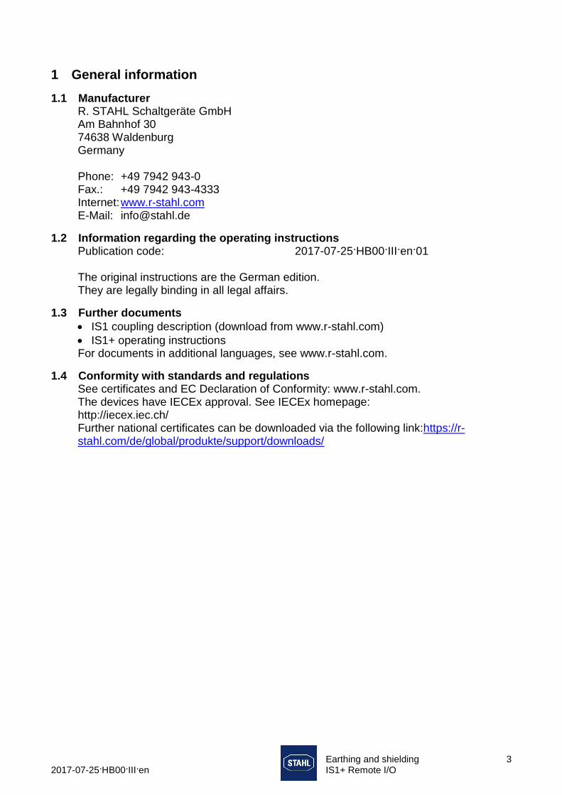
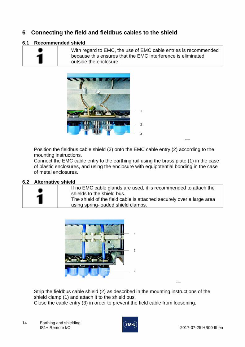