scientific and technological alliance for guaranteeing the ... · scientific and technological...
TRANSCRIPT
Scientific and Technological Alliance for Guaranteeing the European Excellence in
Concentrating Solar Thermal Energy
FP7 Grant Agreement number: 609837 Start date of project: 01/02/2014 Duration of project: 48 months
Project Deliverable 7.4:
White Paper on “Compatibility of structural materials with storage
materials for TES system”
WPX – Task 7.2 Deliverable 7.4
Due date: February/2017
Submitted March/2017
Partner responsible CIEMAT
Person responsible Marta Navas
Author(s):
M.Navas (CIEMAT), E. Gonzalez, C. Prieto (Abengoa), A. Bonanos (CyI), T. Bauer, A. Bonk (DLR), S. Sau (ENEA), T.Fluri, J. Preussner (FISE), A. Gomes, T.C. Diamantino (LNEG), J.I. Burgaleta (SENER), J. Nieto (Tecnalia), L. Guerreiro (UEVORA)
Document version: 1
Reviewed/supervised by: Walter Gagglioli
Dissemination Level Public

D7.4 White Paper compatibility of structural materials with storage materials for TES
DELIVERABLE 7.4 1
Table of contents
1. INTRODUCTION .......................................................................................................... 5
2. STRUCTURAL MATERIALS/SOLAR MOLTEN SALTS COMPATIBILITY ......... 6
2.1. Introduction and molten salt background .................................................................. 6
2.2. Corrosion testing in molten salts ............................................................................... 9
2.2.1. Methodology of corrosion tests ........................................................................ 10
2.2.2. Parameters to be controlled .............................................................................. 12
2.2.3. Critical issues on corrosion results ................................................................... 12
2.3. Corrosion results in nitrate molten salts .................................................................. 13
2.3.1. Conclusions of corrosion results ...................................................................... 18
3. COMMERCIAL PLANTS ........................................................................................... 19
3.1. Overview description of the storage system with MS and two tanks ...................... 19
3.1.1. General overview of the process (PTC) ........................................................... 19
3.1.2. Salts Storage Tanks .......................................................................................... 20
3.1.3. Heat Exchangers ............................................................................................... 20
3.1.4. Salts Pumps ...................................................................................................... 20
3.1.5. Salts Recirculation ............................................................................................ 21
3.1.6. Drainage System .............................................................................................. 21
3.1.7. HTF and Leak Detection Condensate System .................................................. 21
3.1.8. Nitrogen System ............................................................................................... 21
3.2. Material compatibility under real conditions of operation up to 400ºC .................. 21
3.3. Main requirements for structural materials ............................................................. 26
3.4. Recommendations for inspections ........................................................................... 27
3.4.1. Salts Storage Tanks .......................................................................................... 27
3.4.2. Heat Exchangers, Salt Pumps, Valves ............................................................. 27
4. NEW DEVELOPMENTS............................................................................................. 28
4.1. Filler materials for thermocline tank storage ........................................................... 28
4.1.1. Recommendations ............................................................................................ 31
4.1.2. Compatibility with structural materials ............................................................ 32
4.2. Concrete based thermal storage ............................................................................... 32
4.2.1 Future Research ................................................................................................ 38
4.3. Other molten salts for TES systems ........................................................................ 38
4.3.1. Structural materials compatibility .................................................................... 39
4.4. Liquid metal ............................................................................................................. 41

D7.4 White Paper compatibility of structural materials with storage materials for TES
DELIVERABLE 7.4 2
4.4.1. Material degradation by liquid metals .............................................................. 41
4.4.2. Compatibility of structural materials with metallic PCM ................................ 42
4.4.3. Compatibility of materials with Lead and Lead Bismuth Eutectic .................. 45
4.4.4. Critical issues ................................................................................................... 48
5. CONCLUSIONS .......................................................................................................... 50
6. REFERENCES ............................................................................................................. 51

D7.4 White Paper compatibility of structural materials with storage materials for TES
DELIVERABLE 7.4 3
Figures Figure 1. Scheme of interaction of molten salt anions with structural materials (e.g., steel) and atmosphere ......................................................................................................................... 8
Figure 2. Schematic drawing of the corrosion system ............................................................. 8 Figure 3. Kinetic laws of uniform corrosion as function of depth of attack .......................... 10
Figure 4. Weight gain over time in a immersion test for different temperatures in a 60 wt.% NaNO3 and 40 wt.% KNO3 salt mixture; “ind” indicates industrial grade salt and “ref” refined grade salt. No descaling method was applied. [Preussner 2016]. .............................. 14
Figure 5. Corrosion rate of AISI 321 coupons exposed for different immersion intervals at 550 ºC [Uranga D7.3 2016]. ................................................................................................... 15 Figure 6. a) XRD pattern; b) Optical image and top view SEM images of the oxide scales formed and c) Semi quantitative line scans and corresponding back scattered image of AISI 321 after 3000 h immersed in solar salt (source LNEG). ....................................................... 16 Figure 7. Schematic curve of SSRT test showing SCC in a corrosive media (left). A measured curve of 347Nb steel in air and in molten salt [Preussner 2016]. .......................... 17
Figure 8. The steel Sanicro 25 tested in 60 wt.% NaNO3 and 40 wt.% of KNO3 salt mixture at a temperature of 565 °C (ε = 10-3 1/s, 10x slower� ε = 10-4 1/s, Rε = -1). ..................... 18
Figure 9. Abengoa TES-PS10 Molten salt demonstration plant (source: Abengoa) ............. 22
Figure 10. Types of A516 Gr.70 corrosion coupons (source: Abengoa) ............................... 23
Figure 11. Corrosion coupons after salts exposure: (a) 1680 h, (b) 4064 h, (c) 8712 h, (d) crevice coupon, (e) SCC coupon (source: Abengoa) ............................................................. 24 Figure 12. Solana solar thermal power plant with two-tank molten salt storage system (source: Abengoa) .................................................................................................................. 26
Figure 13. Standard deviation vs. mean of the elementary effects, as evaluated using Morris’ screening method. ................................................................................................................... 31
Figure 14. Prefabricated tube registers being installed in a concrete storage test module at DLR [Laing 2011]. ................................................................................................................. 34
Figure 15. Scheme of the piping bundle according to [Laing 2006] ...................................... 34
Figure 16. Location of the piping bundle with triangular pitch and elementary cell [Bai 2009]. ...................................................................................................................................... 35
Figure 17. Test Module without isolation [Laing 2008b]. ..................................................... 35 Figure 18. Concrete based Mixture Properties [Emerson 2013]. ........................................... 36
Figure 19. Austenitic steel AISI 316L tested in lead–bismuth under an atmosphere with a H2/H2O ratio of 0.03 at 535, 550 and 600 ºC (Source CIEMAT) .......................................... 46
D7.4 White Paper compatibility of structural materials with storage materials for TES
DELIVERABLE 7.4 4
Tables Table 1. Properties of selected anhydrous inorganic salts and salt mixtures for TES and HTF applications sorted by anion and melting temperature. ............................................................ 6 Table 2. Elemental composition of the AISI 321 stainless steel (wt.%) ................................ 15
Table 3. Elemental composition carbon steel A516. Gr 70 ................................................... 23 Table 4. Corrosion rates for the three exposure times ............................................................ 24 Table 5. Guide for corrosion rates used in the industry (adapted for A516 Gr.70) ............... 25
Table 6. Summary of thermo-physical properties of common thermocline filler materials .. 28
Table 7. Range of parameters investigated in sensitivity analysis ......................................... 29 Table 8. Main characteristics of solid materials for sensible heat storage [NREL 2000] ...... 33
Table 9. Properties of materials developed by DLR [Laing 2006] ........................................ 33
Table 10. Particle size distribution, CAC and BFS [Alonso 2016] ........................................ 37
Table 11. Dosage CAC and CAC+ concrete in kg/m3 [Alonso 2016] ................................... 37
D7.4 White Paper compatibility of structural materials with storage materials for TES
DELIVERABLE 7.4 5
1. INTRODUCTION
The purpose of this white paper is to outline the knowledge of the compatibility of the storage materials and structural materials for TES system. The main objective of this White Paper is to establish the critical issues requiring attention on materials compatibility and also the critical unknowns and research needs. The paper will first provide an introduction of the information regarding structural materials with the Solar Molten Salt based on corrosion studies, but also the lessons learned on the commercial CSP plants.
There are various ways to describe and classify TES materials and systems. Most commonly three types of TES systems are distinguished [Bauer 2012]:
- Sensible heat storage results in an increase or decrease of the storage material temperature; stored energy is proportional to the temperature difference of the used materials. The major sensible heat storage types are:
o Solids o Liquids o Mixed systems with solids and liquids
- Latent heat storage is connected with a phase transformation of the storage materials (phase change materials, PCM), typically changing their physical phase from solid to liquid and vice versa. The phase change is always coupled with the absorption or release of heat and occurs at a constant temperature. Thus, the heat added or released cannot be sensed and appears to be latent. Stored energy is equivalent to the heat (enthalpy) for melting and freezing.
- Thermochemical heat storage is based on reversible thermochemical reactions. The energy is stored in the form of chemical compounds created by an endothermic reaction and is recovered again by recombining the compounds in an exothermic reaction. The heat stored and released is equivalent to the heat (enthalpy) of reaction.
The main emphasis of this document is on molten salt compatibility with structural materials. In addition, the chapter Future Developments focuses on other concepts:
- Sensible heat storage with mixed systems of solids and liquids: Filler materials like natural rocks in direct contact with molten salt
- Sensible heat storage with mixed systems of solids and liquids: Concrete in direct contact with molten salt
- Sensible heat storage in liquids: alternative molten salt mixtures - Sensible heat storage in liquids: liquid metal - Latent heat storage: metallic phase change materials (PCMs)
D7.4 White Paper compatibility of structural materials with storage materials for TES
DELIVERABLE 7.4 6
2. STRUCTURAL MATERIALS/SOLAR MOLTEN SALTS COMPATIBILITY
2.1. Introduction and molten salt background
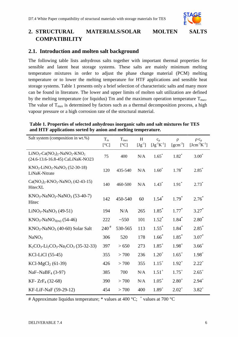
The following table lists anhydrous salts together with important thermal properties for sensible and latent heat storage systems. These salts are mainly minimum melting temperature mixtures in order to adjust the phase change material (PCM) melting temperature or to lower the melting temperature for HTF applications and sensible heat storage systems. Table 1 presents only a brief selection of characteristic salts and many more can be found in literature. The lower and upper limits of molten salt utilization are defined by the melting temperature (or liquidus) Tm and the maximum operation temperature Tmax. The value of Tmax is determined by factors such as a thermal decomposition process, a high vapour pressure or a high corrosion rate of the structural material.
Table 1. Properties of selected anhydrous inorganic salts and salt mixtures for TES and HTF applications sorted by anion and melting temperature.
Salt system (composition in wt.%) Tm [°C]
Tmax [°C]
H [Jg-1]
cp
[Jg-1K-1] ρ
[gcm-3] ρ·cp
[Jcm-3K-1]
LiNO3-Ca(NO3)2-NaNO2-KNO2 (24.6-13.6-16.8-45) CaLiNaK-NO23
75 400 N/A 1.65* 1.82* 3.00*
KNO3-LiNO3-NaNO3 (52-30-18) LiNaK-Nitrate
120 435-540 N/A 1.60* 1.78* 2.85*
Ca(NO3)2-KNO3-NaNO3 (42-43-15) HitecXL
140 460-500 N/A 1.43* 1.91* 2.73*
KNO3-NaNO2-NaNO3 (53-40-7) Hitec
142 450-540 60 1.54* 1.79* 2.76*
LiNO3-NaNO3 (49-51) 194 N/A 265 1.85* 1.77* 3.27*
KNO3-NaNO3(eu) (54-46) 222 ~550 101 1.52* 1.84* 2.80*
KNO3-NaNO3 (40-60) Solar Salt 240 # 530-565 113 1.55* 1.84* 2.85*
NaNO3 306 520 178 1.66* 1.85* 3.07*
K2CO3-Li 2CO3-Na2CO3 (35-32-33) 397 > 650 273 1.85+ 1.98+ 3.66+
KCl-LiCl (55-45) 355 > 700 236 1.20+ 1.65+ 1.98+
KCl-MgCl2 (61-39) 426 > 700 355 1.15+ 1.92+ 2.22+
NaF–NaBF4 (3-97) 385 700 N/A 1.51+ 1.75+ 2.65+
KF- ZrF4 (32-68) 390 > 700 N/A 1.05+ 2.80+ 2.94+
KF-LiF-NaF (59-29-12) 454 > 700 400 1.89+ 2.02+ 3.82+
# Approximate liquidus temperature; * values at 400 °C; + values at 700 °C

D7.4 White Paper compatibility of structural materials with storage materials for TES
DELIVERABLE 7.4 7
For PCM applications, the specific material investment costs (e.g., € kWh-1) are determined by the PCM costs (e.g., € kg-1) and the melting enthalpy H (e.g., J kg-1). Hence, PCMs should have low material costs and high melting enthalpies. For sensible heat storage, specific material investment costs (e.g., € kWh-1) are determined by the material costs (e.g., € kg-1), the heat capacity cp and the temperature difference between charging and discharging ∆T. The specific volumetric heat capacity is the product of the density ρ and the heat capacity cp. The product ρ·cp is an important characteristic value for heat transfer fluids (HTFs) and it determines the size of a sensible heat storage system. The volumetric energy density ρ·cp varies typically from 2.0 J cm-3 K-1 to 3.8 J cm-3 K-1 (see table). [Bauer 2013a] [Bauer 2016 D7.1].
Anions can be classified into the groups of nitrates, nitrate/nitrite mixtures, carbonates, chlorides and fluorides (see Table 1). For CSP, state-of-the-art TES fluids consist of alkali metal nitrate salt mixtures. There is some laboratory and prototype experience with other nitrate and nitrite mixtures (e.g. Hitec, HitecXL). CSP experience with other anhydrous oxyanion salts (e.g., carbonates) and halogen salts (e.g., fluorides, chlorides) is currently mainly limited to theoretical studies and laboratory measurements. In future, the utilization of nitrate salts could be restricted by their thermal stability limits, if higher operation temperatures are required. For applications at higher temperatures, salts with other anions, such as carbonates, chlorides and fluorides are potential candidates.
The remainder of this chapter considers the state-of-the-art nitrate salts. For sensible heat storage in CSP plants, almost exclusively a non-eutectic molten salt mixture with 60wt% sodium nitrate (NaNO3) and 40wt% potassium nitrate (KNO3) is utilized. This mixture is usually known as “Solar Salt” with an increased amount of the NaNO3. NaNO3 is typically cheaper and has a higher heat capacity compared to KNO3. The non-eutectic mixture has a liquidus temperature of about 240 °C and the thermal stability limit is about 550 °C.
Figure 1 shows a simplified scheme of the molten salt anions and cations in the melt [Bauer 2013a][Federsel 2015][Nissen 1983]. For molten salt chemistry the anionic reactions are relevant. Different reactions may occur within the melt and due to interaction of the molten salt with the atmosphere and the structural material (e.g. steel):
- Salt conversion or decomposition with gas release (e.g. formation of nitrite with oxygen release, formation of oxides with nitrogen or nitrogen oxide release)
- Absorption of gases and formation of anionic species (e.g. CO2 absorption with carbonate formation, moisture absorption with hydroxide formation)
- Dissolution of metallic elements from structural materials in molten salt (e.g. chromium in steel with chromate formation in the melt)

D7.4 White Paper compatibility of structural materials with storage materials for TES
DELIVERABLE 7.4 8
Figure 1. Scheme of interaction of molten salt anions with structural materials (e.g., steel) and atmosphere
Figure 2 shows the corrosion system with a structural material (e.g., steel), molten salt as attacking medium (environment) and in some cases additional stresses. It can be seen that there are several parameters for the structural material and the molten salt which affect the corrosion system.
Figure 2. Schematic drawing of the corrosion system
The major metallic structural materials for Solar Salt are low-alloyed carbon steel and stainless Cr-Ni steel (with and without alloying elements such as Mo, Nb, Ti).
It is known that corrosion rates increase for higher impurity levels of dissolved chloride and oxide species in the molten salt [Federsel 2015].
For reliable long-term application and in particular at high temperatures (e.g., >500 °C), there is still a lack of knowledge about steel corrosion mechanisms in nitrate melts. Research aspects of the corrosion system include:

D7.4 White Paper compatibility of structural materials with storage materials for TES
DELIVERABLE 7.4 9
- Type and stability of protective oxide layers on structural materials - Impact of stresses on the corrosion system - Impact of molten salt flow on corrosion system - Impact of molten salt chemistry on corrosion
� Type of salt mixture (e.g. ternary salt mixtures) � Impurity level (e.g. chloride, oxide)
- Interaction between molten salt and metallic structural materials (e.g. chromium dissolution with chromate formation in the melt)
- Coatings for metallic structural materials to minimize corrosion.
2.2. Corrosion testing in molten salts
This section focuses on the corrosion testing considering different aspects like: type of corrosion tests and its methodology, the most important parameters for testing and the interpretation of test results in order to evaluate the structural material degradation.
The goal of the laboratory corrosion tests under simulated operating conditions is to identify and to understand the contributions of the different variables; to quantify the extent of corrosion and to make predictions of plant component behaviour. Information regarding to type of degradation, corrosion kinetic law or impurities effect is relevant for the design, the operation and the maintenance strategy of the CSP plants. One of the main objectives is to optimize the couple structural material/quality storage material taking into account the total cost of the system.
In order to select the best type of corrosion studies the most important aspect is the type of corrosion that will be studied. There are two mechanisms of materials corrosion in molten salts: the metal dissolution of the material constituents and the oxidation of the metal to ions. The last one is the main degradation mechanism and it causes the uniform corrosion of materials in molten salts like nitrate mixtures. In any case, both processes can be mitigated by the formation and stability of protective oxide layers.
Corrosion tests have to simulate as close as possible the operating conditions of CSP plants, with different maximum operating temperatures. The evaluation of the uniform corrosion is mainly performed by means of weight measurements of the specimens immersed on the environmental during certain testing times and these values are converted to corrosion rates, expressed as weight or thickness loss per unit of time (considering the alloy density) with different units like mdd, mm/year or µm/year [ASTM G31].
Furthermore the evolution of the corrosion rates at different time intervals allows the determination of the kinetic law (Figure 3). Corrosion rates follow parabolic or logarithmic laws when the oxide material is protective or a linear law when the material is continuously dissolved. Usually, the corrodibility of the material during the test may decrease as a function of time because the material is oxidized up to the formation of protective scale and the parabolic law is obtained. In this case, the service life of the component can be estimated on the basis of the corrosion kinetic law. The duration of test is a key factor in order to evaluate it with enough accuracy and it depends on the material and molten salt couple.

D7.4 White Paper compatibility of structural materials with storage materials for TES
DELIVERABLE 7.4 10
Figure 3. Kinetic laws of uniform corrosion as function of depth of attack
Allowable corrosion rates are different for each type of material, equipment or design lifetime. Extra-thickness of the component can be increased to consider thickness losses by corrosion named as “corrosion allowance” in order to assure the service life of the component. This value, based on corrosion tests results, depends on the engineering design and it is different for each material application of the different equipment.
2.2.1. Methodology of corrosion tests
Different methodologies of corrosion laboratories tests can be selected depending on the type of corrosion or the different parameters to be studied:
- Immersion corrosion tests under static conditions
The most widespread corrosion results of the literature data are related to immersion corrosion tests on isothermal conditions. A static corrosion test is usually used for screening and it is especially interesting for comparing materials, salts or other variables that can influence the corrosion behaviour.
Static immersion tests are performed in furnaces or autoclaves which operate at controlled temperature and gas atmosphere, for long exposure time [ASTM G31] [ISO 17245]. At the end of the specimen immersion, material corrosion is evaluated by weight measurements to determine both weight gain, due to the incorporation of the oxygen into the oxide layers, and weight loss after the removal of oxide layer and corrosion products.
- Immersion corrosion tests under dynamic conditions
In order to complete the information, it is desirable to perform experiments under isothermal conditions and flowing molten salts, in particular where storage materials to be flowed inside the pipelines. Corrosion rates can be strongly influenced by the fluid velocity when oxide layers are not enough protective.
Corrosion studies may be conducted in thermal convection or forced convection loops. According to ENEA experience, gathered during past experimental campaigns prevalently carried out at MOSE facility, which is a molten salts recirculating system, the following conditions for specimens and thermal fluids are considered appropriate:

D7.4 White Paper compatibility of structural materials with storage materials for TES
DELIVERABLE 7.4 11
- Specimen dimensions: - Height: around 50 mm - Width: around 25 mm - Thickness: around 3 mm
- At least two molten thermal fluid velocities are to be applied: 0.25 (m/s) and 1 (m/s). - At least one temperature as near as possible to the thermal stability limit of the fluid: - Not below 550 °C for the solar salt, as an instance. Temperature(s) should be the
same of the one(s) used for static corrosion tests. - A contact time: From 2000 to 8000 hours (at least 2000 h to obtain reliable results of
lifetime extrapolation)
Usually the corrosion tests in molten salts recirculating loops apply fluid velocities up to 1 m/s. However higher velocities up to 3m/s are desirable to simulate the operating conditions of some components of the commercial plant. In that case, it is also possible to perform dynamic tests by using a rotating system which keeps the specimens or the molten salt under movement at high velocities values. With this methodology, it is necessary to avoid the occurrence of cavitation phenomena at the interface between molten salts and materials.
- Thermal cycling tests
Thermal cycling tests consist of an intermittent immersion which simulates the effects of the rise and fall of liquid and the wet of the molten nitrates [Bradshaw 2001]. The primary effect of thermal cycling is to damage protective surface layers via mechanical stresses arising from mismatched thermal expansion coefficients between the surface scale and the alloy.
Literature data are present for these experiments where temperature was varied, according to realistic applications from about 300 °C to 550 °C (considering the solar salt). Hence those literature indications are to be followed for eventual tests of that kind.
- Stress Corrosion Cracking tests
Stress corrosion cracking (SCC) is a localized corrosion due to the formation of cracks for the simultaneous presence of a susceptible material, aggressive environment and a stress level over a threshold value. Most tests have a screening nature in order to discard the SCC susceptibility of the alloys and its weldments in nitrate molten salts. SCC susceptibility can be studied with immersion corrosion of stressed specimens like: C-ring [ASTM G38] for tubes, U-bend [ASTM G30] and Bent Beam Specimens [ASTM G39] for plates.
Other susceptibility tests, like Slow strain rate tests (SSRT), implies the application of external load usually in Constant Extension Rate Tests (CERT) with low displacement rate. SSRT is usually performed until the rupture of specimen and the susceptibility is determined by a ductility loss comparing with inert environments. Fracture surface examination is necessary to detect the intergranular facets of the cracks due to SCC.
D7.4 White Paper compatibility of structural materials with storage materials for TES
DELIVERABLE 7.4 12
2.2.2. Parameters to be controlled
For proper planning of the test and interpretation of results, the specific influences of the following variables must be carefully considered:
• Temperature: The temperature should be controlled especially in the case of static corrosion tests in furnaces or autoclaves. Usually two different baseline operating temperature ranges of CSP commercial plants are tested: 390 ºC and 560 ºC.
• Gas atmosphere: Different gas atmosphere must be used depending on the CSP technology. Inert gas is used when operating conditions of parabolic trough plant are simulated or nitrate and nitrite mixture salt is tested.
• Testing time: Corrosion tests must carried out at least during 2000 hours to define accurate corrosion rates. Long exposure tests, with intermediate stops and higher testing times (5000 or 7000 h), are necessary to determine reliable corrosion rates and to define a reliable parabolic kinetic law.
• Chemical composition of molten salts. The purity/quality of molten salts is a key aspect regarding the formation of a protective oxide layer, especially the chloride concentration. A study on the chemical evolution of the salts is also necessary with the chemical analyses of abovementioned anions (Figure 1).
• Specimen surface: Corrosion tests may be performed with a laboratory surface finishing (abrasives with mean particle of 15 µm) or same material product of the component studied (tubes or plates) with the finished surface found in service. In the last case, a previous study of the initial surface defects must be done to evaluate their evolution. Usually the choice of material tested depends on the researching or engineering purposes of the study.
• Ratio of structural material surface/molten salts volume can influence the corrosion results especially when the solubility of metals alloy like chromium can be produced.
• Shape and size of the specimens can vary depending on the material and product type. Specimens may be flat, disc, tube ring and son on depending on the material type (plate, bar or tube). In any case it is necessary accurate measurements of initial and final weight and dimensions of specimens.
• Specimen type: Other aspects like the effect of weld procedure, crevice (metal surface is partially blocked from the corroding liquid with simulate occluded sites) or SCC can be studied with the proper type of specimens.
2.2.3. Critical issues on corrosion results
For proper interpretation of testing results the abovementioned key factors must be simulated as close as possible to the operating plant conditions. In addition, corrosion results are usually based on corrosion rates but firstly it is necessary to study the corrosion processes like uniform corrosion, localized attack, descaling, thickness of the oxidation layer and so on, by means of microscopic examination (optical or scanning electron microscopy).
Only if no localized attack is detected, (like pitting, dealloying or intergranular attack), corrosion results based on gravimetric measurements are reliable and accurate. Gain weight measurements (oxide layer formation) can be used to infer corrosion rates only when the adherence of oxide layers is proved and high descaling or spalling process are discarded.
D7.4 White Paper compatibility of structural materials with storage materials for TES
DELIVERABLE 7.4 13
Corrosion rates based on the weight loss must be accurately evaluated and the procedure for removing corrosion products and oxide layers must be carefully selected for each material/environment. Cleaning procedure may be done chemical, electrolytic or mechanical depending on the properties of oxide layers. An ideal procedure should assure that the cleaning removes the whole oxide layer formed without dissolution of the metal elements or other attack. A good practice is to check it by means of the cleaning blank specimens.
When a high material oxidation is occurred, optical measurement of the remained thickness of abovementioned metallographic specimens may be used to quantify the corrosion rate based on the depth of attack and to compare it with corrosion rate determined by mass loss. Also, thickness measurement of the oxide layer detected may be useful to compare material behaviour on screening tests.
Other post-test examination techniques may provide additional information to study the corrosion process like chemical composition of oxide layers and molten salt. Corrosion scale analyses can be performed using different techniques, depending on the thickness and nature of oxide layers: SEM EDX, Auger Electron Spectroscopy, Electron Spectroscopy for Chemical Analysis, and so on.
Finally, chemical analyses of the molten salts at intermediate stops are very useful to study the chemical composition changes like nitrite formation, due to the thermal degradation, or the solubility of metal element like chromium.
Therefore, corrosion studies are necessary when new molten salt mixtures are developed or a temperature increase is searching for TES system. In addition, the final choice of the couple structural/storage material must be assessed with corrosion tests and taking into account the total cost of the TES system.
2.3. Corrosion results in nitrate molten salts
The operating temperature is often the primary consideration regarding the selection of material for a specific component. Corrosion studies of TES have demonstrated some behaviour differences between structural materials and the following range of temperature are accepted:
- Carbon steels: at temperature below 400ºC - Carbon steels with chromium and molybdenum up to 500ºC - Stainless steels or nickel base alloys at the highest temperature.
Carbon steels are the first candidate for the components of the TES system when the operation temperature allows its use due to its lowest cost. Corrosion studies have demonstrated that the metal loss rate of these materials are acceptable for tank construction although depends strongly on the temperature and the salt quality, especially on the chloride content. These materials are protected against uniform corrosion in molten salts due to the formation of pseudo-protective iron oxide layer.
D7.4 White Paper compatibility of structural materials with storage materials for TES
DELIVERABLE 7.4 14
At low temperatures corrosion rates of A36 carbon steel, measured by metal losses, are
around 1- 4µm/year tested at 316ºC in air [Goods 1994]. This corrosion rate increase at operating condition with inert gas and high temperature. Corrosion rate of carbon steel under real operating condition is detailed in the following section of this deliverable.
At elevated temperatures, nitrate ions decompose giving rise to nitrite ions and oxygen. These strong oxidizing species combined with high operating temperatures plus salt impurities generate propitious conditions for corrosion acceleration of stainless steels (SS). In this context, it is crucial to evaluate the corrosion resistance and lifetime of stainless steels to optimize the material selection since their failure could lead to severe damage of the CSP plants operation.
Due to the high operating temperature, austenitic stainless steels have been identified as especially suitable materials in the storage system [Bauer 2013b] [Dorcheh 2016] [Goods 2004]. Low alloy steels often reveal insufficient corrosion behaviour [Fernandez 2012]. From the literature, the Solar Salt is compatible with 316, 304 and 347 austenitic stainless steels, with metal losses less which vary between than 4-15 µm/year [Pacheco 2002b] [Goods 1994]. Additionally, corrosion studies have shown that AISI 347 and AISI 321 had very little oxidation for 400 and 500 °C, being the corrosion rates of AISI 347 consistently lower in comparison to AISI 321 by 40-50% at temperatures of 600°C and below [Kruizenga 2014]. Most of the tests available in the literature are conducted as static immersion tests in liquid molten salt over a certain period of time.
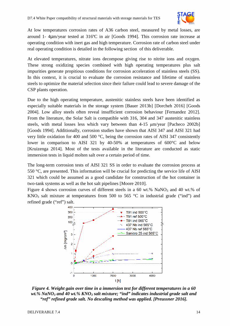
The long-term corrosion tests of AISI 321 SS in order to evaluate the corrosion process at 550 °C, are presented. This information will be crucial for predicting the service life of AISI 321 which could be assumed as a good candidate for construction of the hot container in two-tank systems as well as the hot salt pipelines [Moore 2010]. Figure 4 shows corrosion curves of different steels in a 60 wt.% NaNO3 and 40 wt.% of KNO3 salt mixture at temperatures from 500 to 565 °C in industrial grade (“ind”) and refined grade (“ref”) salt.
Figure 4. Weight gain over time in a immersion test for different temperatures in a 60 wt.% NaNO3 and 40 wt.% KNO3 salt mixture; “ind” indicates industrial grade salt and
“ref” refined grade salt. No descaling method was applied. [Preussner 2016].
D7.4 White Paper compatibility of structural materials with storage materials for TES
DELIVERABLE 7.4 15
The ferritic-martensitic chromium steel (T91) shows insufficient corrosion behaviour, but demonstrates various effects: a higher corrosion rate with increasing temperature and a higher corrosion rate in industrial grade salt compared to the refined grade. Stainless steels (437Nb and Sanicro 25) indicate considerably less corrosion.
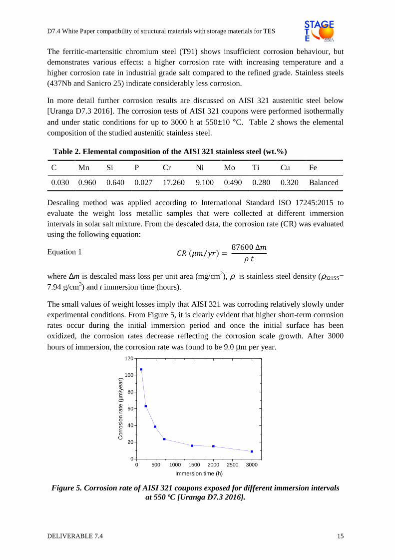
In more detail further corrosion results are discussed on AISI 321 austenitic steel below [Uranga D7.3 2016]. The corrosion tests of AISI 321 coupons were performed isothermally
and under static conditions for up to 3000 h at 550±10 °C. Table 2 shows the elemental composition of the studied austenitic stainless steel.
Table 2. Elemental composition of the AISI 321 stainless steel (wt.%)
C Mn Si P Cr Ni Mo Ti Cu Fe
0.030 0.960 0.640 0.027 17.260 9.100 0.490 0.280 0.320 Balanced
Descaling method was applied according to International Standard ISO 17245:2015 to evaluate the weight loss metallic samples that were collected at different immersion intervals in solar salt mixture. From the descaled data, the corrosion rate (CR) was evaluated using the following equation:
Equation 1 ����� ��⁄ � 87600∆�
��
where ∆m is descaled mass loss per unit area (mg/cm2), ρ is stainless steel density (ρ321SS= 7.94 g/cm3) and t immersion time (hours).
The small values of weight losses imply that AISI 321 was corroding relatively slowly under experimental conditions. From Figure 5, it is clearly evident that higher short-term corrosion rates occur during the initial immersion period and once the initial surface has been oxidized, the corrosion rates decrease reflecting the corrosion scale growth. After 3000 hours of immersion, the corrosion rate was found to be 9.0 µm per year.
Figure 5. Corrosion rate of AISI 321 coupons exposed for different immersion intervals at 550 ºC [Uranga D7.3 2016].
0 500 1000 1500 2000 2500 30000
20
40
60
80
100
120
Cor
rosi
on r
ate
(µm
/yea
r)
Immersion time (h)
D7.4 White Paper compatibility of structural materials with storage materials for TES
DELIVERABLE 7.4 16
25 30 35 40 45 50 55 60 65
FeCr2O4
Fe3O
4
�
�
�
�
�
�
�
�
�
��
���
�
2 θ (degrees)
3000 h 0 h
�
�
�
Fe2O
3
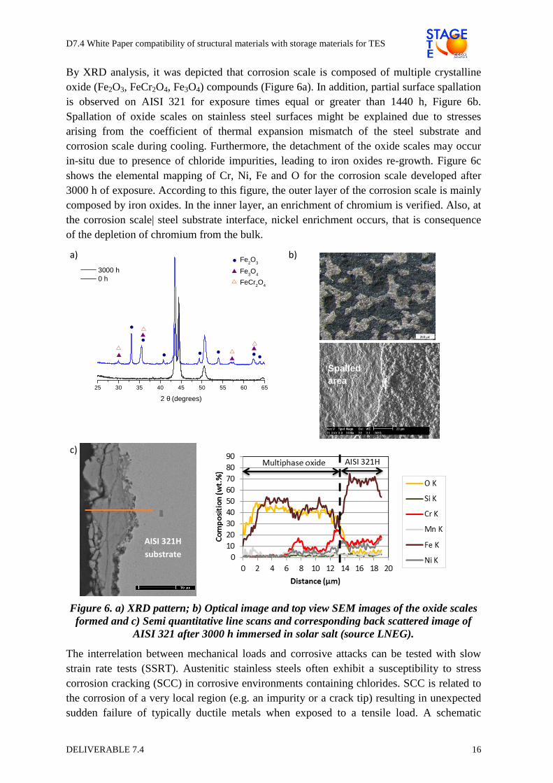
By XRD analysis, it was depicted that corrosion scale is composed of multiple crystalline oxide (Fe2O3, FeCr2O4, Fe3O4) compounds (Figure 6a). In addition, partial surface spallation is observed on AISI 321 for exposure times equal or greater than 1440 h, Figure 6b. Spallation of oxide scales on stainless steel surfaces might be explained due to stresses arising from the coefficient of thermal expansion mismatch of the steel substrate and corrosion scale during cooling. Furthermore, the detachment of the oxide scales may occur in-situ due to presence of chloride impurities, leading to iron oxides re-growth. Figure 6c shows the elemental mapping of Cr, Ni, Fe and O for the corrosion scale developed after 3000 h of exposure. According to this figure, the outer layer of the corrosion scale is mainly composed by iron oxides. In the inner layer, an enrichment of chromium is verified. Also, at the corrosion scale| steel substrate interface, nickel enrichment occurs, that is consequence of the depletion of chromium from the bulk.
a)
b)
c)
Figure 6. a) XRD pattern; b) Optical image and top view SEM images of the oxide scales formed and c) Semi quantitative line scans and corresponding back scattered image of
AISI 321 after 3000 h immersed in solar salt (source LNEG).
The interrelation between mechanical loads and corrosive attacks can be tested with slow strain rate tests (SSRT). Austenitic stainless steels often exhibit a susceptibility to stress corrosion cracking (SCC) in corrosive environments containing chlorides. SCC is related to the corrosion of a very local region (e.g. an impurity or a crack tip) resulting in unexpected sudden failure of typically ductile metals when exposed to a tensile load. A schematic
Spalled area
AISI 321H
substrate

D7.4 White Paper compatibility of structural materials with storage materials for TES
DELIVERABLE 7.4 17
drawing of the phenomenon of SCC can be seen in Figure 7 left with the help of a stress-strain curve of a slow strain rate (SSR) tensile test. The premature failure of the sample exposed to the corrosive medium is depicted.
Figure 7 right displays results of slow strain rate tests of bone shaped tensile test samples out of 347H tested in air and in nitrate salt environment (60 wt.% NaNO3, 40 wt.% of KNO3) [Preussner 2016]. A small effect of the environment can be seen on the accomplished total strain, however the data on such tests is up to now very limited. Only few tests in salt under superimposed mechanical load have been published.
Figure 7. Schematic curve of SSRT test showing SCC in a corrosive media (left). A measured curve of 347Nb steel in air and in molten salt [Preussner 2016].
Nearly no data are available for cyclic mechanical tests or thermomechanical tests in nitrate salt environments. However, fatigue is a realistic load case in a TES system due to the daily heating and cooling of the components that comes along with an elongation and shrinking of pipes due to thermal expansion.
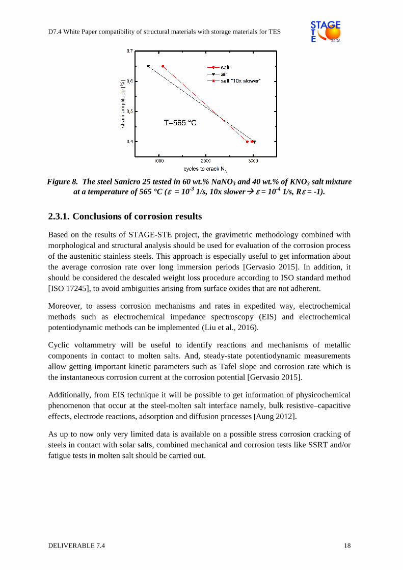
Figure 8 shows test results from a low cycle fatigue (LCF) test of Sanicro 25 tube specimens with nitrate salt (60 wt.% NaNO3, 40 wt.% of KNO3) inside the tubes that are exposed to a strain amplitude of εA = 0.65 % and εA = 0.4 % (Rε=-1) respectively [Preussner 2016]. The strain rates used for these tests were ε;˙ = 10-3 1/s, which lead to test times of 7 h and 13 h. An additional test, marked with “10x slower” in the graph was tested in salt with εA = 0.4 % (Rε = -1) and ε;˙ = 10-4 1/s to achieve longer testing times, here 6 days, and promote possible corrosion. With the selected steel and the relatively short testing times, no evidence of accelerated crack growth in salt environment is evident.
D7.4 White Paper compatibility of structural materials with storage materials for TES
DELIVERABLE 7.4 18
Figure 8. The steel Sanicro 25 tested in 60 wt.% NaNO3 and 40 wt.% of KNO3 salt mixture at a temperature of 565 °C (ε = 10-3 1/s, 10x slower� ε = 10-4 1/s, Rε = -1).
2.3.1. Conclusions of corrosion results
Based on the results of STAGE-STE project, the gravimetric methodology combined with morphological and structural analysis should be used for evaluation of the corrosion process of the austenitic stainless steels. This approach is especially useful to get information about the average corrosion rate over long immersion periods [Gervasio 2015]. In addition, it should be considered the descaled weight loss procedure according to ISO standard method [ISO 17245], to avoid ambiguities arising from surface oxides that are not adherent.
Moreover, to assess corrosion mechanisms and rates in expedited way, electrochemical methods such as electrochemical impedance spectroscopy (EIS) and electrochemical potentiodynamic methods can be implemented (Liu et al., 2016).
Cyclic voltammetry will be useful to identify reactions and mechanisms of metallic components in contact to molten salts. And, steady-state potentiodynamic measurements allow getting important kinetic parameters such as Tafel slope and corrosion rate which is the instantaneous corrosion current at the corrosion potential [Gervasio 2015].
Additionally, from EIS technique it will be possible to get information of physicochemical phenomenon that occur at the steel-molten salt interface namely, bulk resistive–capacitive effects, electrode reactions, adsorption and diffusion processes [Aung 2012].
As up to now only very limited data is available on a possible stress corrosion cracking of steels in contact with solar salts, combined mechanical and corrosion tests like SSRT and/or fatigue tests in molten salt should be carried out.
D7.4 White Paper compatibility of structural materials with storage materials for TES
DELIVERABLE 7.4 19
3. COMMERCIAL PLANTS
3.1. Overview description of the storage system with MS and two tanks
A thermal storage system allows the continue plant operation during the time of day when radiation is reduced or after sunset. In this system, the solar energy stored during the day shall be stored in a body of salt in liquid form. The TES system storage capacity is designed according to each plant necessity. The environment in which the thermal energy is stored consists of a molten salt mixture with a weight composition of 60% of NaNO3 and 40% of KNO3.
The Thermal Energy Storage System consists of the following main elements:
• Storage of Cold Salts - Storage tank of cold molten salts - Electric heaters submerged in the tank or external heating system with
recirculation - Cold molten salts pumps with electric motors and variable speed drives - Eductors for the mixing of cold salts
• Heat exchangers - Molten salt heat exchangers
• Storage of Hot Salts - Storage tank of hot molten salts - Electric heaters submerged in the tank or external heating system with
recirculation - Hot molten salt pumps with electric motors and variable speed drives
• Drainage system - Drainage receptacle, to empty the pipes and heat exchangers (molten salts side) - Drain Pump or pneumatical system to return the salts to the cold salt tank
• Leak Detection System
• Nitrogen inerting systems (Parabolic Trough Collector PTC Plans)
3.1.1. General overview of the process (PTC)
The molten salts are stored in two tanks. Cold molten salts are stored cold at 290/310 ºC in one tank, depending on the operation. The salts go through a series of heat exchangers, and are heated from 290 ºC / 310 ºC to 385 ºC by the HTF (Heat Transfer Fluid), from the Solar Field, during sunshine hours. The salts heated to 385 ºC are stored in another tank, the hot salts tank, so that the heat energy can be returned to the HTF during the non-sunshine hours. In this event, the hot salts are sent to the cold salts Tank.
The Thermal Storage Capacity will be designed to secure full load Gross Capacity during the Peak Hours and according to each plant necessity.
D7.4 White Paper compatibility of structural materials with storage materials for TES
DELIVERABLE 7.4 20
During the thermal loading and discharging processes, the transfer of nitrogen from one tank to another is carried out through a junction manifold between the two.
3.1.2. Salts Storage Tanks
The storage tanks of molten salts are vertical cylinders made of carbon steel and are insulated in order to minimize heat loss through the walls and ceiling thereof.
The main elements of the tanks are as follows:
• Salts Distribution Ring. Used to receive and distribute the salts in the receiving tank. It basically consists of a vertical tube that enters through the top of the tank and reaches the bottom, where there is a ring of the same diameter and is perforated along its entire length. In this way, the fluid will be distributed at various points within the tank.
• Mixing Ring. This ring shall be equipped with only the cold tank. Its mission is to homogenize the temperature in the cold salts tank. The molten salts entering the tank through the roof and are conducted to an inner nozzle ring and empties in a collector ring at the bottom of the tank. The collector is equipped with eductors receiving this mixture.
• Nitrogen System. Given the possible presence of HTF, due to a ruptured pipe in one of the heat exchangers, the tanks are rendered inert with nitrogen.
• Electric Heaters. At the bottom of each tank, there shall be electric heaters to replace the loss of heat through the walls and bottom or in an external recirculation system.
• Pressure-vacuum safety valves. The tank will be equipped with safety valves to prevent overpressure and to break the vacuum. A pressure safety valve shall also be installed to evacuate the normal flow of excess nitrogen under normal operation.
• Ground cooling pipes under the salts tank.
3.1.3. Heat Exchangers
Shell and tube heat exchangers are used to transfer the heat energy contained in the HTF to the molten salts and thus store the hot salts at 385 ºC. In the same heat exchange operations, the salts fused at night or under low insolation transfer their thermal energy to the HTF and cool down, from 385 °C to 290/310 ºC.
Oil is the fluid with the highest pressure and it will circulate through the tubes while the molten salts will circulate through the shell. The exchangers shall have insulation and electric heat tracing to prevent the salts from freezing.
3.1.4. Salts Pumps
To pump the salts from one tank to another vertical pumps, installed in the tanks, submerged in the salts are used.

D7.4 White Paper compatibility of structural materials with storage materials for TES
DELIVERABLE 7.4 21
Ensure the integrity of the tanks and avoid heat losses in exterior pipes between the tank and the buried tanks, is a reason to install the pumps inside the tanks.
The required number of pumps will be defined according operation ranges, and the pumps motor will be located on a structure over the tank.
3.1.5. Salts Recirculation
The main purpose of the recirculation system is the homogenization of the temperature of the salts in the cold tank. The recirculation system enables the salts to recirculate during the storage waiting hours through the lines and Heat Exchangers by means of the manual operation of one of the cold tank pumps. The recirculated salts are released into the cold tank through the bottom via eductors installed in the collector ring.
3.1.6. Drainage System
There will be a drainage tank available which will collect the drainage of the pipes and heat exchangers and shall be fitted with a submerged vertical pump or a pneumatic system.
3.1.7. HTF and Leak Detection Condensate System
The objectives of the HTF and leak detection condensate system are as follows:
• Detect a leak as soon as it occurs. • Separate the HTF present in the salts circuit. • Identify the exact location where the leak occurs.
3.1.8. Nitrogen System
A nitrogen supply will be provided for the following main functions:
• Maintain the salts storage tanks, hot and cold tanks, and the drainage tank inert. The nitrogen atmosphere is necessary to ensure that there is no oxygen present in the event that there is HTF in any of the tanks due to a rupture in one of the exchanger tubes.
• Nitrogen supply to the heat exchanger system for inerting and pressurizing the line and facilitate the pumping of salts from the cold tank.
• Cooling the pumps of the cold salts storage tank, hot salts storage tank and the drainage tank if required.
3.2. Material compatibility under real conditions of operation up to 400ºC
Material selection for the different equipment and components of commercial TES systems has become a key issue in CSP. In addition, material compatibility in terms of corrosion is also required. Corrosion phenomena could result in the deterioration of material properties compromising its validity for the final application for which they were designed. As the elimination of corrosion phenomena would not be feasible, it is the key to prevent and mitigate techno-economic issues resulting from corrosion.

D7.4 White Paper compatibility of structural materials with storage materials for TES
DELIVERABLE 7.4 22
The different components of a TES system need to be optimized from metallic alloys corrosion allowance point of view. Service life and performance during almost 30 years of operation and minimization of commercial TES cost, are two of the main concerns regarding steel material optimization.
To deal with these problematics Abengoa planned the design, construction and evaluation of a molten salt TES system.
• TES-PS10 demonstration plant to test corrosion performance up to 400ºC
The TES-PS10 demonstration plant located in the Solúcar Platform near Seville (Spain) consists of a two-tank indirect TES system using a mixture of 60% NaNO3 and 40% KNO3 by weight close to the eutectic composition (also called “Solar Salt”). The plant is connected to Repow PS10 demonstration plant, consisting of a 600 m parabolic trough collector loop using thermal oil as heat transfer fluid. The storage capacity of TES-PS10 is 8.1 MWhth.
The main objective of TES-PS10 was to build and validate a complete molten salt thermal energy storage system in a sufficient size to be upscaled for commercial plants. The demonstration plant was satisfactorily evaluated during 32000 h between years 2009-2012.
Among others, corrosion performance of metallic alloys in contact with nitrate salt mixtures was evaluated. And more precisely, the corrosion performance of carbon steel up to 400 ºC and at different exposure times. The main objective was to simulate real operating conditions as a commercial-scale TES system could have in service.
Therefore, a Corrosion Testing Device (CTD) was designed to evaluate corrosion behaviour of structural materials inside high temperature nitrate salts storage tanks in operation [Ruiz-Cabañas 2016]. The material selected was the carbon steel A516 Gr.70, as it is the typical carbon steel used in the manufacturing of molten salts storage tanks in current commercial plants. Corrosion tests were conducted in the hot tank of the TES-PS10 pilot plant (Figure 9) which maximum operating temperature was 390 ºC.
Figure 9. Abengoa TES-PS10 Molten salt demonstration plant (source: Abengoa)
D7.4 White Paper compatibility of structural materials with storage materials for TES
DELIVERABLE 7.4 23
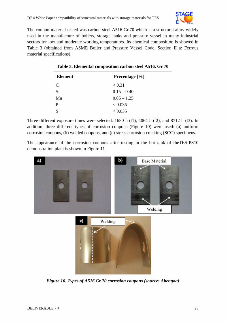
The coupon material tested was carbon steel A516 Gr.70 which is a structural alloy widely used in the manufacture of boilers, storage tanks and pressure vessel in many industrial sectors for low and moderate working temperatures. Its chemical composition is showed in Table 3 (obtained from ASME Boiler and Pressure Vessel Code, Section II a: Ferrous material specifications).
Table 3. Elemental composition carbon steel A516. Gr 70
Element Precentage [%]
C < 0.31
Si 0.15 – 0.40
Mn 0.85 – 1.25
P < 0.035
S < 0.035
Three different exposure times were selected: 1680 h (t1), 4064 h (t2), and 8712 h (t3). In addition, three different types of corrosion coupons (Figure 10) were used: (a) uniform corrosion coupons, (b) welded coupons, and (c) stress corrosion cracking (SCC) specimens.
The appearance of the corrosion coupons after testing in the hot tank of theTES-PS10 demonstration plant is shown in Figure 11.
Figure 10. Types of A516 Gr.70 corrosion coupons (source: Abengoa)
D7.4 White Paper compatibility of structural materials with storage materials for TES
DELIVERABLE 7.4 24
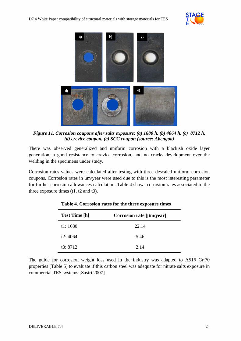
Figure 11. Corrosion coupons after salts exposure: (a) 1680 h, (b) 4064 h, (c) 8712 h, (d) crevice coupon, (e) SCC coupon (source: Abengoa)
There was observed generalized and uniform corrosion with a blackish oxide layer generation, a good resistance to crevice corrosion, and no cracks development over the welding in the specimens under study.
Corrosion rates values were calculated after testing with three descaled uniform corrosion coupons. Corrosion rates in µm/year were used due to this is the most interesting parameter for further corrosion allowances calculation. Table 4 shows corrosion rates associated to the three exposure times (t1, t2 and t3).
Table 4. Corrosion rates for the three exposure times
Test Time [h] Corrosion rate [µm/year]
t1: 1680 22.14
t2: 4064 5.46
t3: 8712 2.14
The guide for corrosion weight loss used in the industry was adapted to A516 Gr.70 properties (Table 5) to evaluate if this carbon steel was adequate for nitrate salts exposure in commercial TES systems [Sastri 2007].
D7.4 White Paper compatibility of structural materials with storage materials for TES
DELIVERABLE 7.4 25
Table 5. Guide for corrosion rates used in the industry (adapted for A516 Gr.70)
Corrosion rate [µm/year]
Recommendation
> 1275 Completely destroyed within days
127 - 1274 Not recommended for service greater than 1 month
64 – 126 Not recommended for service greater than 1 year
14 – 63 Caution recommended, based on the specific application
0.4 - 13 Recommended for long term service
< 0.3 Recommended for long term service; no corrosion (other than as result of surface cleaning) was evidenced
A significant decrease of the corrosion rate values were observed while increasing time exposure. This performance was indicative of the formation of protective oxide layers producing the passivation of the carbon steel.
• Conclusions
The results of TES-PS10 corrosion tests shows that carbon steel A516 Gr.70 has an excellent corrosion performance in contact with nitrate salts at 390 °C. Uniform corrosion rates are recommended for long term service as happening in commercial CSP plants where an estimated life of 25-30 years is considered. Also, corrosion rates decreases through time because of the generation of protective oxide layers by the effect of passivation of the carbon steel.
These results confirm the suitability of carbon steel A516 Gr.70 as a structural material to be used in both cold and hot tanks of a two-tank indirect TES system using Solar Salt, as it is the case in all of the storage tanks installed by Abengoa in their commercial CSP plants.
Solana (Figure 12) and KaXu Solar One are two commercial examples. Solana, a 280 MW parabolic trough plant in commercial operation since 2013 and located in Arizona (USA), uses a 6h two-tank indirect thermal energy storage system with 135000 tons of molten salt inventory. On the other hand, KaXu Solar One plant, located in Pofadder (South Africa), has 100 MW and a 2.5h two-tank indirect TES system in operation since March 2015. KaXu Solar One TES system has an inventory of 22000 tons. As the exposure times for the corrosion tests described previously are representative but not long enough, both plants are monitored with corrosion testing devices in order to obtain further long-term corrosion results in commercial operation.

D7.4 White Paper compatibility of structural materials with storage materials for TES
DELIVERABLE 7.4 26
Figure 12. Solana solar thermal power plant with two-tank molten salt storage system (source: Abengoa)
3.3. Main requirements for structural materials
Based upon the temperatures and type of salts, provided in point 3.1 about storage system conditions, carbon steel and low alloy steel material can be considered as suitable. Depending on the chemical composition of the salts proposed, corrosion over-thickness shall be considered.
Regarding requirements for structural materials as pumps, piping, tanks and/or valves, definition of the static and dynamic mechanical testing required for each combination of fluid-structural material shall be required. Characterization of each material based on short and long term testing shall be considered in order to validate final properties related to actual operation conditions.
For this purpose these tests are considered relevant and shall be applied as appropriate for each material. Metallographic for macro and microstructure examination; tensile stress values; hardness verification; impact testing; creep; fatigue at low and high cycle tests will be proposed. Corrosion tests for specific corrosion types related to the applicable manufacturing processes, main type equipment and parts configuration, e.g, stress corrosion, pitting, crevice; or minor surface variations and their impact in cycle properties, shall be performed.
D7.4 White Paper compatibility of structural materials with storage materials for TES
DELIVERABLE 7.4 27
Testing Definition:
For each material to be used in main structural component, testing standards, parameters, conditions, shall be defined as follows:
- Selection of test fluids, environments and conditions; - Different manufacturing process of structural materials shall be tested, e.g.
castings, forgings, rolling materials; - Definition of samples to be tested; - Temperatures, loads and cycling as needed; - Number of test to be carried out; - Acceptance criteria for each type of testing;
Main requirements for structural materials shall be based on the monitoring, analysis and evaluation of above testing samples.
3.4. Recommendations for inspections
3.4.1. Salts Storage Tanks
Tanks shall be manufactured and inspected in accordance with design code requirements; in most tanks, according to API 650.
The material used for the nitrate salt tanks and salt containment at temperatures below 400°C shall be carbon steel; with specific material requirements as per section 3.3.
All the tanks welding processes, sequences and inspections will be described in a written procedure that shall be supported by the corresponding Welding Qualification procedure fully in accordance with the design code.
Scope and acceptance criteria of dimensional control of the tank, hardness testing on welds, non-destructive examination on welds and hydraulic testing shall be in accordance with the applicable design code. Specific Local and/or Country Regulations shall be also taken into account.
3.4.2. Heat Exchangers, Salt Pumps, Valves
Heat exchangers, salt pumps, valves and other static or dynamic equipment shall be manufactured and tested in accordance with corresponding design code; always provided that local or country regulations are fulfilled.
Materials to be used for mentioned equipment at temperatures below 400 °C shall be carbon steel; with specific material requirements as per section 3.3.
Manufacturing processes and quality control activities shall be supported by specific procedures that shall be in accordance with the corresponding design code.

D7.4 White Paper compatibility of structural materials with storage materials for TES
DELIVERABLE 7.4 28
4. NEW DEVELOPMENTS
4.1. Filler materials for thermocline tank storage
The desirable characteristics of filler materials for thermocline storage tanks may be summarized as:
i) Favourable thermal properties, ii) Filler material rigidity through expected operating temperature range, iii) Chemical compatibility with heat transfer fluid, iv) Availability and low-cost
A literature survey of experimental studies employing packed bed thermocline energy storage tanks was conducted to summarize the materials used by various researchers and tabulate the relevant thermos-physical properties of each material, as summarized in Table 6. In most cases, molten solar salt was used as the heat transfer fluid; however this is not exclusively true for all materials noted.
Table 6. Summary of thermo-physical properties of common thermocline filler materials
Material
ρ Cp ρ Cp k Tmin Tmax Reference [kg/m3] [J/kg-K] [MJ/m 3K] [W/m-K] [°C] [°C]
Reinforced concrete
2200 850 1.87 1.5 200 400 [Kuravi 2013]
N4 concrete
2250 1100 2.475 1.3 200 400 [Laing 2008]
High T Concrete
2750 916 2.519 1
[Laing 2006]
Cast iron 7200 560 4.032 37 200 400 [Kuravi 2013 NREL 2000]
Cast steel 7800 600 4.68 40 200 700 [Kuravi 2013, NREL 2000]
Silica fire bricks
1820 1000 1.82 1.5 200 700 [Kuravi 2013 NREL 2000]
Magnesia fire bricks
3000 1150 3.45 5 200 1200 [Kuravi 2013 NREL 2000]
Castable ceramic
3500 866 3.031 1.35
[Laing 2006]
NaCl (solid)
2160 850 1.836 7 200 500 [NREL2000]
Alumina porcelain
2700 880 2.376 2.1
>650 [Zunf 2011]
Graphite 1700 1900 3.23 200
>1500 [Forsberg 2007]
Quartzite 2620 620 1.624 3.4
>650 [Zanganeh2012]
Limestone 2700 670 1.809 2.5
>650 [Zanganeh 012]
Steatite 2680 1068 2.862 2.5
>550 [Hanchen 2011]
Cofalit 3120 860 2.683 2.7
[Py 2009]
Granite 2893 845 2.445 3 [Chang 2014]
D7.4 White Paper compatibility of structural materials with storage materials for TES
DELIVERABLE 7.4 29
The information in Table 6 may be used to establish the range of variation of the parameters of the filler materials, from a thermal point of view. To identify the most suitable filler material, a systematic sensitivity analysis of the thermocline system must be performed.
The thermocline model developed by Votyakov and Bonanos [Votyakov 2014] [Votyakov 2015] is used and the thermocline thickness after a complete charging is identified as the metric of interest to be minimized, as it is directly related to the tank efficiency. The thermocline thickness may be evaluated as
Equation 2
−+=
NuL
ds
f
p
)1(6
PrRe4
PrRe
4
επγ
βπελ
where dp is the mean diameter of the filler material particles, L is the tank height, ε is the porosity, Re, Pr and Nu the Reynolds, Prandtl and Nusselt number of the heat transfer fluid, βf the share of thermal conductivity of the heat transfer fluid and γs the share of volumetric heat capacity of the filler material.
The definition of the thermocline thickness captures in total 9 parameters, which are considered in a sensitivity analysis, to deduce which has the largest influence. These are L, dp, ε (defined above), volumetric heat capacity of the fluid and solid (ρCp,f, ρCp,s), thermal conductivity of fluid and solid (kf, ks), fluid viscosity (νf) and charging velocity (u). The parameters and their range of variation investigated in the present work are summarized in Table 7 [Bonanos 2016].
Table 7. Range of parameters investigated in sensitivity analysis
Parameter Min. Max. Nominal Unit dp 0.001 0.1 0.01 [m] L 1 20 10 [m] ε 0.05 0.5 0.22 [--] kf 0.01 60 1.0 [W/m-K] ks 0.1 200 1.0 [W/m-K] (ρCp)f 1.0 4.5 2.5 [MJ/m3-K] (ρCp)s 1.0 5.0 2.5 [MJ/m3-K] t 6 12 9 [hours] νf 0.05 5 0.5 [µm2/s]
The thermocline model used allows for the evaluation of the thermocline thickness through an algebraic equation, as opposed to differential equations typically used in the literature; thus making the evaluation much faster. The model therefore is ideal for performing sensitivity analysis methodologies that typically rely on Monte-Carlo statistical methods and therefore require a very large number of function evaluations.
A one-at-a-time (OAT) screening method was applied to determine the relative importance of the input parameters. Morris' method is chosen as it allows classification of inputs in three categories: those having negligible effect on the output, those with large linear effects but no interactions and those with nonlinear and/or interaction effects [Morris 1991] [Iooss 2015].

D7.4 White Paper compatibility of structural materials with storage materials for TES
DELIVERABLE 7.4 30
In this method, the so called elementary effects (E) are evaluated by computing the effect of a step change, ∆, of the ith model input, where ∆ uniformly samples the variable's input domain. The experiment is repeated r times to sample r different trajectories, resulting in a computational cost of n = r(p + 1) model evaluations, where p is the number of input variables. Then, the elementary effect of the jth variable (j = 1…k) on the ith repetition (i = 1…r), Ei
j, is evaluated as
Equation 3
∆−∆+= ),...,(),...,,...,( 11 kkii
j
xxfxxxfE
After evaluating all elementary effects, their mean and standard deviations may be evaluated as
Equation 4 |,|
1
1
ij
r
ij E
r∑
=
=µ
where the modified version of the mean, using the absolute value of the elementary effect, is used, and
Equation 5 )
1(
1
11∑∑
==
−=r
i
ij
ij
r
ij E
rE
rσ
The mean, µj, is a measure of the influence of the jth input on the output; the larger the mean the more the jth input contributes to the dispersion of the output. The standard deviation, σj, is a measure of the non-linear and/or interaction effects of the jth input: a small σj implies a similar effect on the output along the input range, in other words the output is independent of the choice of the value of the parameter [Saltelli 2004, Iooss 2015].
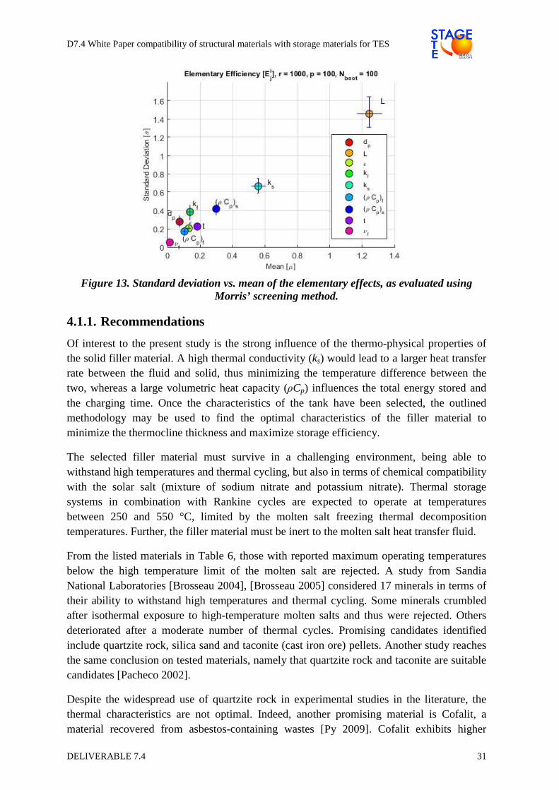
The SAFE toolbox (R1.1, [Pianosi 2015]), implementing Morris' screening technique was used for the analysis of the thermocline thickness. The input parameters were assumed to vary uniformly in the identified range (c.f. Table 7). In the model, r = 1000 elementary effects where evaluated on a grid with p = 50 levels. Bootstrapping of 100 samples was applied in order to determine the upper and lower bounds of the mean and standard deviation with a significance level of 5%. From the analysis, shown in Figure 13, the following conclusions may be drawn:
• Inputs L, ks and (ρCp)s have a strong influence with non-linear and/or interaction effects, since µ and σ are of the same order of magnitude.
• Inputs dp, kf, ε, (ρCp)f and u have a moderate influence on the output. Further, the order of importance of the variables may not be clearly determined, as the mean has a similar magnitude for these inputs.
• Input νf has no influence on the model output and may be considered constant.
D7.4 White Paper compatibility of structural materials with storage materials for TES
DELIVERABLE 7.4 31
Figure 13. Standard deviation vs. mean of the elementary effects, as evaluated using Morris’ screening method.
4.1.1. Recommendations
Of interest to the present study is the strong influence of the thermo-physical properties of the solid filler material. A high thermal conductivity (ks) would lead to a larger heat transfer rate between the fluid and solid, thus minimizing the temperature difference between the two, whereas a large volumetric heat capacity (ρCp) influences the total energy stored and the charging time. Once the characteristics of the tank have been selected, the outlined methodology may be used to find the optimal characteristics of the filler material to minimize the thermocline thickness and maximize storage efficiency.
The selected filler material must survive in a challenging environment, being able to withstand high temperatures and thermal cycling, but also in terms of chemical compatibility with the solar salt (mixture of sodium nitrate and potassium nitrate). Thermal storage systems in combination with Rankine cycles are expected to operate at temperatures between 250 and 550 °C, limited by the molten salt freezing thermal decomposition temperatures. Further, the filler material must be inert to the molten salt heat transfer fluid.
From the listed materials in Table 6, those with reported maximum operating temperatures below the high temperature limit of the molten salt are rejected. A study from Sandia National Laboratories [Brosseau 2004], [Brosseau 2005] considered 17 minerals in terms of their ability to withstand high temperatures and thermal cycling. Some minerals crumbled after isothermal exposure to high-temperature molten salts and thus were rejected. Others deteriorated after a moderate number of thermal cycles. Promising candidates identified include quartzite rock, silica sand and taconite (cast iron ore) pellets. Another study reaches the same conclusion on tested materials, namely that quartzite rock and taconite are suitable candidates [Pacheco 2002].
Despite the widespread use of quartzite rock in experimental studies in the literature, the thermal characteristics are not optimal. Indeed, another promising material is Cofalit, a material recovered from asbestos-containing wastes [Py 2009]. Cofalit exhibits higher
D7.4 White Paper compatibility of structural materials with storage materials for TES
DELIVERABLE 7.4 32
volumetric heat capacity but lower conductivity than quartzite, so should also be considered as a promising material.
The final consideration for filler materials is the financial aspect; materials must be cheap, as their objective is to offset the high-cost of the heat transfer fluid. All identified materials above are either abundant naturally occurring (quartzite, silica) or waste by products of other processes (taconite, Cofalit) and thus are not expensive.
4.1.2. Compatibility with structural materials
Thermal ratcheting may occur over time as the packed bed is thermally cycled. A report by [Libby 2010] discusses this issue for quartzite rock as the filler material, but the phenomenon is present when there is a volume change of the filler material with temperature. As the quartzite rock filler is cooled it contracts and compacts in the bottom of the tank. When the tank is reheated the quartzite cannot return to its original position. The quartzite then expands and places pressure on the walls of the tank. Over time this process could potentially damage the tank [Libby 2010].
Concerns about thermal ratcheting were raised during the construction and evaluation of the thermal storage subsystem of Solar One. Thermal stresses in the tank wall were monitored with strain gages; however their results suffered from large uncertainty in the measurements of the employed strain gages. Additionally, the thermal storage subsystem was only used sporadically, limiting the thermal cycles the tank went through [Faas 1983]. Under these conditions, they report that thermal ratcheting was not an issue in their design. The mechanical stress issue on the thermocline tank wall was later investigated by [Flueckiger 2011] using finite element analysis and analytical techniques. They investigate the thermal stresses developed under various tank wall heat transfer boundary conditions and conclude that the stresses can be accurately predicted by simple analytical techniques given the temperature distribution on the tank wall. To avoid ratcheting, they recommend increasing the insulation between the insulation between the filler material and the tank wall [Flueckiger 2011].
4.2. Concrete based thermal storage
Solid sensible heat storage is an attractive option for high-temperature storage applications regarding investment and maintenance costs. Using concrete as solid storage material is most suitable, as it is easy to handle, the major aggregates are available all over the world, and there are no environmentally critical components. Thermal energy storage can be done in liquid medium (molten salts, thermal oil) or in solid medium (ceramic, sand bed, rock, concrete) [Tian 2013], where concrete is a promising candidate due to its low cost and because it is easy to prepare and install. It also has a good heat capacity, good mechanical properties and an appropriate coefficient of thermal expansion [Emerson 2010], being easily applicable and suitable for the case study.
D7.4 White Paper compatibility of structural materials with storage materials for TES
DELIVERABLE 7.4 33
For a material to be viable in a thermal energy storage application, it cannot be very expensive and has to have a good thermal capacity. Another important parameter in sensible thermal storage is the rate at which heat can be released or extracted.
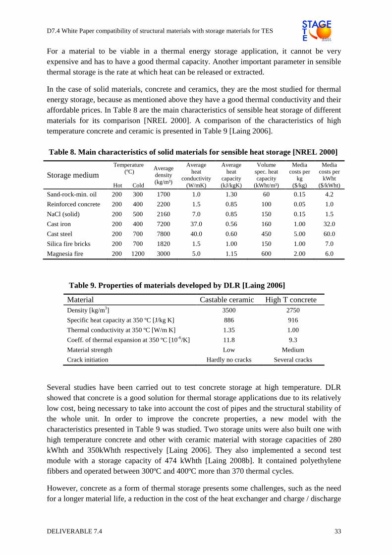
In the case of solid materials, concrete and ceramics, they are the most studied for thermal energy storage, because as mentioned above they have a good thermal conductivity and their affordable prices. In Table 8 are the main characteristics of sensible heat storage of different materials for its comparison [NREL 2000]. A comparison of the characteristics of high temperature concrete and ceramic is presented in Table 9 [Laing 2006].
Table 8. Main characteristics of solid materials for sensible heat storage [NREL 2000]
Storage medium Temperature
(ºC)
Hot Cold
Average density (kg/m³)
Average heat
conductivity (W/mK)
Average heat
capacity (kJ/kgK)
Volume spec. heat capacity
(kWht/m³)
Media costs per
kg ($/kg)
Media costs per
kWht ($/kWht)
Sand-rock-min. oil 200 300 1700 1.0 1.30 60 0.15 4.2
Reinforced concrete 200 400 2200 1.5 0.85 100 0.05 1.0
NaCl (solid) 200 500 2160 7.0 0.85 150 0.15 1.5
Cast iron 200 400 7200 37.0 0.56 160 1.00 32.0
Cast steel 200 700 7800 40.0 0.60 450 5.00 60.0
Silica fire bricks 200 700 1820 1.5 1.00 150 1.00 7.0
Magnesia fire 200 1200 3000 5.0 1.15 600 2.00 6.0
Table 9. Properties of materials developed by DLR [Laing 2006]
Material Castable ceramic High T concrete Density [kg/m3] 3500 2750
Specific heat capacity at 350 ºC [J/kg K] 886 916
Thermal conductivity at 350 ºC [W/m K] 1.35 1.00
Coeff. of thermal expansion at 350 ºC [10-6/K] 11.8 9.3
Material strength Low Medium
Crack initiation Hardly no cracks Several cracks
Several studies have been carried out to test concrete storage at high temperature. DLR showed that concrete is a good solution for thermal storage applications due to its relatively low cost, being necessary to take into account the cost of pipes and the structural stability of the whole unit. In order to improve the concrete properties, a new model with the characteristics presented in Table 9 was studied. Two storage units were also built one with high temperature concrete and other with ceramic material with storage capacities of 280 kWhth and 350kWhth respectively [Laing 2006]. They also implemented a second test module with a storage capacity of 474 kWhth [Laing 2008b]. It contained polyethylene fibbers and operated between 300ºC and 400ºC more than 370 thermal cycles.
However, concrete as a form of thermal storage presents some challenges, such as the need for a longer material life, a reduction in the cost of the heat exchanger and charge / discharge

D7.4 White Paper compatibility of structural materials with storage materials for TES
DELIVERABLE 7.4 34
problems. Efforts have been made to improve the material to avoid rupture and increase thermal conductivity to improve heat transfer [Martins 2015].
Depending on the heat transfer fluid chosen, a concrete storage system should be designed and validated in order to optimize the heat transfer occurring both in the charge as well as in the discharge process. Up to now, concrete storage has been thought to work either with thermal oil or with steam, however, other fluids might also be considered.
Laing have investigated a storage system of heat capacity of 1MWh consisting of concrete and PCM storage [Laing 2011], [Laing 2012]. Sensible Heat Storage unit is used during the preheating/cooling of condensate and superheating/cooling of steam period. However, Latent Heat Storage unit of PCMs is used during the evaporation/condensation period. The geometrical configuration of the rectangular unit is shown in Figure 14.
Figure 14. Prefabricated tube registers being installed in a concrete storage test module at DLR [Laing 2011].
A storage unit is composed by a piping bundle embedded within concrete for allowing fluid flow through it. The pipes, in the solution proposed by DLR [Laing 2006], are parallel one to the other with axes at a distance ‘da’ and arranged according to a squared pitch Figure 15, whereas according to the solution of [Bai 2009], they are arranged following a triangular pitch Figure 16.
Figure 15. Scheme of the piping bundle according to [Laing 2006]
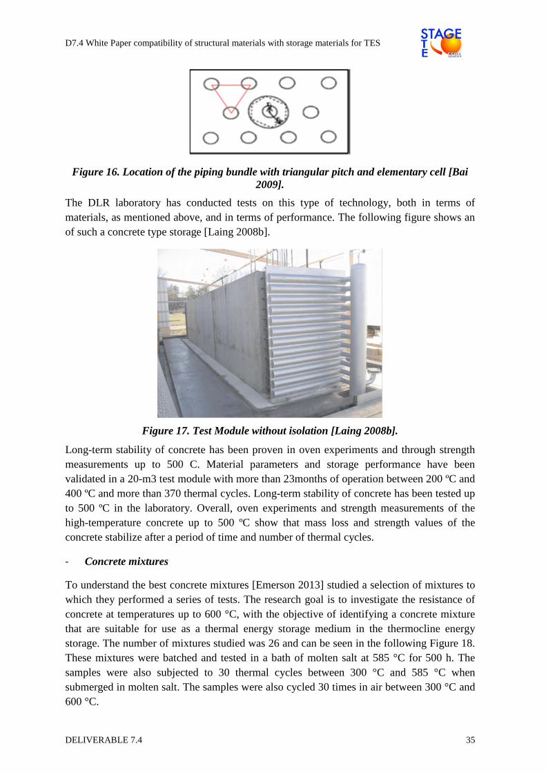
D7.4 White Paper compatibility of structural materials with storage materials for TES
DELIVERABLE 7.4 35
Figure 16. Location of the piping bundle with triangular pitch and elementary cell [Bai 2009].
The DLR laboratory has conducted tests on this type of technology, both in terms of materials, as mentioned above, and in terms of performance. The following figure shows an of such a concrete type storage [Laing 2008b].
Figure 17. Test Module without isolation [Laing 2008b].
Long-term stability of concrete has been proven in oven experiments and through strength measurements up to 500 C. Material parameters and storage performance have been validated in a 20-m3 test module with more than 23months of operation between 200 ºC and 400 ºC and more than 370 thermal cycles. Long-term stability of concrete has been tested up to 500 ºC in the laboratory. Overall, oven experiments and strength measurements of the high-temperature concrete up to 500 ºC show that mass loss and strength values of the concrete stabilize after a period of time and number of thermal cycles.
- Concrete mixtures
To understand the best concrete mixtures [Emerson 2013] studied a selection of mixtures to which they performed a series of tests. The research goal is to investigate the resistance of concrete at temperatures up to 600 °C, with the objective of identifying a concrete mixture that are suitable for use as a thermal energy storage medium in the thermocline energy storage. The number of mixtures studied was 26 and can be seen in the following Figure 18. These mixtures were batched and tested in a bath of molten salt at 585 °C for 500 h. The samples were also subjected to 30 thermal cycles between 300 °C and 585 °C when submerged in molten salt. The samples were also cycled 30 times in air between 300 °C and 600 °C.
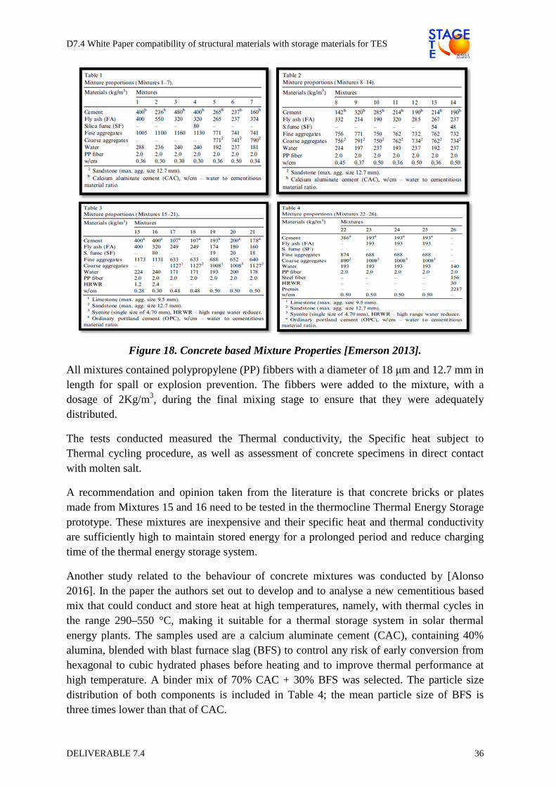
D7.4 White Paper compatibility of structural materials with storage materials for TES
DELIVERABLE 7.4 36
Figure 18. Concrete based Mixture Properties [Emerson 2013].
All mixtures contained polypropylene (PP) fibbers with a diameter of 18 µm and 12.7 mm in length for spall or explosion prevention. The fibbers were added to the mixture, with a dosage of 2Kg/m3, during the final mixing stage to ensure that they were adequately distributed.
The tests conducted measured the Thermal conductivity, the Specific heat subject to Thermal cycling procedure, as well as assessment of concrete specimens in direct contact with molten salt.
A recommendation and opinion taken from the literature is that concrete bricks or plates made from Mixtures 15 and 16 need to be tested in the thermocline Thermal Energy Storage prototype. These mixtures are inexpensive and their specific heat and thermal conductivity are sufficiently high to maintain stored energy for a prolonged period and reduce charging time of the thermal energy storage system.
Another study related to the behaviour of concrete mixtures was conducted by [Alonso 2016]. In the paper the authors set out to develop and to analyse a new cementitious based mix that could conduct and store heat at high temperatures, namely, with thermal cycles in the range 290–550 °C, making it suitable for a thermal storage system in solar thermal energy plants. The samples used are a calcium aluminate cement (CAC), containing 40% alumina, blended with blast furnace slag (BFS) to control any risk of early conversion from hexagonal to cubic hydrated phases before heating and to improve thermal performance at high temperature. A binder mix of 70% CAC + 30% BFS was selected. The particle size distribution of both components is included in Table 4; the mean particle size of BFS is three times lower than that of CAC.

D7.4 White Paper compatibility of structural materials with storage materials for TES
DELIVERABLE 7.4 37
Table 10. Particle size distribution, CAC and BFS [Alonso 2016]
Particle size distribution Mean particle size
(µm) 10 25 50 75 90
CAC 0.71 3.68 9.89 23.34 36.40 15.10
BFS 1.11 2.20 3.74 7.50 17.59 4.19
Mortar samples of 4 × 4 × 16 cm using standard siliceous sand (quartz) (1–4 mm), binder-to-sand ratio of 1/3, water-to-cement ratio of 0.44, and 1% of superplasticizer by cement weight (sikament-180 naphthalene based) were prepared with a consistency of 17–18 cm.
For concrete design, two types of aggregates were used, from 0 to 12 mm size:
1) Natural aggregates from crash stone, mainly constituted by quartz and calcite and silicon calcareous aggregate (SCA). The particle sizes are distributed in quartz sand 0–6 mm and coarse 6–12 mm SCA.
2) Aggregates of industrial waste slag from ore processing (SSA). The particle sizes are distributed in fine sand 0–4 mm, middle size 2– 8 mm, and coarse size 4–12 mm. This slag-waste aggregate shows a partially crystalline structure. Also, variation of 25–40% in SiO2 content can be observed by energy-dispersive X-ray microanalysis (EDX); another main component is Fe2O3 (40–60%).
Two different concrete dosages were prepared maintaining the same type and content of CAC+BFS binder, but varying the type of aggregate. The name CAC refers to concrete prepared with 100% of SCA, while the CAC+ identifies concrete made with a mix of 75% SCA+ 25% SSA.
Table 11. Dosage CAC and CAC+ concrete in kg/m3 [Alonso 2016]
Water w/b CAC BFS SCA 0-6
SCA 6-12
SSA 0-4
SSA 4-8
SSA 8-12
SP (%)
CAC 200 0.5 280 120 805 845 - - - 0.8
CAC+ 228 0.57 277 123 698 698 10 149 111 0.8
The samples studied were pre-dried before the exposure to heating cycles to minimize the risk of spalling during the first heating cycle. The drying protocol was 3 days drying at 105 °C to eliminate most of the free water in the capillary pores, but without significantly affecting the hydrated solid phases.
Some results and conclusions that can be drawn from the study observed at the macro-lever are an alteration of mechanical properties under heat cycles concrete; the mixes are affected by heating up to 550 °C. The thermal fatigue of the concrete is overlapped with the dehydration processes during the first slow heat cycle. However, thermal fatigue is clearly the main deleterious process in further heat cycles, as we can conclude by analysing the mechanical strength.
The damage evolution due to thermal cycles is more pronounced in concretes mixes than in mortar, probably as a consequence of the higher aggregate size (maximum 12 mm), that can affect the deterioration of concrete under the heat cycles.
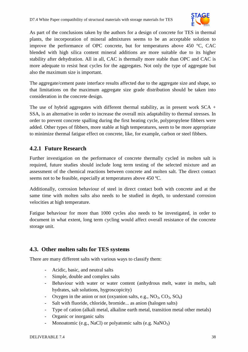
D7.4 White Paper compatibility of structural materials with storage materials for TES
DELIVERABLE 7.4 38
As part of the conclusions taken by the authors for a design of concrete for TES in thermal plants, the incorporation of mineral admixtures seems to be an acceptable solution to improve the performance of OPC concrete, but for temperatures above 450 °C, CAC blended with high silica content mineral additions are more suitable due to its higher stability after dehydration. All in all, CAC is thermally more stable than OPC and CAC is more adequate to resist heat cycles for the aggregates. Not only the type of aggregate but also the maximum size is important.
The aggregate/cement paste interface results affected due to the aggregate size and shape, so that limitations on the maximum aggregate size grade distribution should be taken into consideration in the concrete design.
The use of hybrid aggregates with different thermal stability, as in present work SCA + SSA, is an alternative in order to increase the overall mix adaptability to thermal stresses. In order to prevent concrete spalling during the first heating cycle, polypropylene fibbers were added. Other types of fibbers, more stable at high temperatures, seem to be more appropriate to minimize thermal fatigue effect on concrete, like, for example, carbon or steel fibbers.
4.2.1 Future Research
Further investigation on the performance of concrete thermally cycled in molten salt is required, future studies should include long term testing of the selected mixture and an assessment of the chemical reactions between concrete and molten salt. The direct contact seems not to be feasible, especially at temperatures above 450 ºC.
Additionally, corrosion behaviour of steel in direct contact both with concrete and at the same time with molten salts also needs to be studied in depth, to understand corrosion velocities at high temperature.
Fatigue behaviour for more than 1000 cycles also needs to be investigated, in order to document in what extent, long term cycling would affect overall resistance of the concrete storage unit.
4.3. Other molten salts for TES systems
There are many different salts with various ways to classify them:
- Acidic, basic, and neutral salts - Simple, double and complex salts - Behaviour with water or water content (anhydrous melt, water in melts, salt
hydrates, salt solutions, hygroscopicity) - Oxygen in the anion or not (oxyanion salts, e.g., NO3, CO3, SO4) - Salt with fluoride, chloride, bromide... as anion (halogen salts) - Type of cation (alkali metal, alkaline earth metal, transition metal other metals) - Organic or inorganic salts - Monoatomic (e.g., NaCl) or polyatomic salts (e.g. NaNO3)
D7.4 White Paper compatibility of structural materials with storage materials for TES
DELIVERABLE 7.4 39
In general there is experience with molten nitrate salts from a number of industrial processes related to the heat treatment of metals and heat transfer fluid (HTF) usage. At the time of writing, the major commercial application is the two-tank TES system for sensible heat storage using the nitrate mixture “Solar Salt”. Research and development focuses on alternative alkali nitrate salts with adapted melting temperatures not only for sensible TES, but also for latent heat storage systems.
Since the middle of last century molten halides are commonly used in many industrial processes especially those involving electrolysis because of the high technological importance of these salts as electrolyte media. For instance, the electrolysis of aluminium occurs commonly following the Hall-Héroult process with melts of alumina and cryolite (Sodium aluminium fluoride salt). In the nuclear field, halides salts are employed for the reprocessing of the spent nuclear. Furthermore, fluoride molten salts are investigated since several decades in the frame of the nuclear molten salt reactor concept.
Other molten salt examples include the molten carbonate fuel cell (MCFC) development and the hot corrosion by liquid sulphate melts in incinerators.
In future, the utilization of nitrate salts could be restricted by their thermal stability limits, if higher operation temperatures are required. For applications at higher temperatures, salts with other anions are examined. These are anhydrous oxyanion salts (e.g., carbonates) and halogen salts (e.g., fluorides, chlorides). The work is currently limited to theoretical studies, thermal analysis measurements and laboratory tests. The research focuses on different salt classes:
- Chloride salts [Maksoud 2015] - Carbonate salts - Fluoride salts - Oxide salts / molten glass [Elkin 2014]
4.3.1. Structural materials compatibility
Chloride salts:
Structural materials compatibility: [Lai 2007] reviews the corrosion data generated from different chloride salts at temperatures ranging from 400 to 900 °C for various cast and wrought alloys. No correlation between corrosiveness and alloying element seems to exist but high Ni and low carbon content are preferable. Moreover, it was concluded that the chloride salt melts were too aggressive to be used at high temperatures above 700 °C. [Kruizenga 2012] concludes that increasing the alloying elements such as Mo, W, and Co in Nickel based alloys tended to increase the resistance to corrosion, since they can reduce the solubility of chromium into the chloride salts. Moreover, Ta, another refractory metal, was found to exhibit passivation in chloride salts due to the formation of a poorly soluble compound of Cr (II) and Ta (V) chloride.
Control of corrosion: Since the corrosion rates significantly depend on the concentration of oxide/hydroxide impurities in the chloride salts (Figure 2), considerable research effort is
D7.4 White Paper compatibility of structural materials with storage materials for TES
DELIVERABLE 7.4 40
being made on further treatment on the chloride salts, such as controlled salt dehydration, salt purification, to reduce the corrosive oxidizing impurities in the melts. For instance, it is reported in [Maksoud 2015] and [Kipouros 2001] that when the heating of the salts with strong hydrophilic MgCl2 in the dehydration process is carefully performed, the irreversible decomposition side reactions to the corrosive components MgOHCl and MgO can be controlled at a low level. Some techniques to purify the salts have been developed, e.g., by a chlorinating process (CCl4, HCl, or some other chlorinating compound [Williams 2006]), or by reduction of the salt by using active metals such as Mg [Ambrosek 2011], or saturation of a salt with a liquid metal (i.e., LiCl with Li metal [Mishra 2001] [Indacochea 2001]), to reduce redox potential of the melt.
Carbonate salts:
Structural materials compatibility: [Coyle 1985] concludes that compared to chloride melts, carbonate melts are by far less corrosive, and can be used at temperatures of 900°C. Moreover, it was concluded that Alloys of Ni-Cr-Fe-Mo (alloy X) and Ni-Ce-Fe-Al are amongst the best performing but similar to the chloride melts, no correlation between corrosiveness and alloying element exists to date. However, the investigation of carbonates under atmospheric conditions has been limited and need to be investigated more thoroughly for conditions applicable as TES for CSP [Kruizenga 2012], although it has been studied extensively under Molten Carbonate Fuel Cell (MCFC) conditions, where ullage gases are high in CO2 content.
Control of corrosion: Impurities in the form of oxygen and moisture are much less of an issue in carbonates [Kruizenga 2012]. However, the addition of chlorides will cause accelerated materials degradation. [Zeng 2011] shows that adding 10 wt.% chloride impurities can cause ~25% faster of the corrosion of 304SS. Further investigations by developing rates of corrosion versus impurity concentration need to be established.
Fluoride salts:
Structural materials compatibility: Fluoride melts used as nuclear reactor coolants are very corrosive already below 700 °C [Coyle 1985]. Hastelloy Alloy N is suitable for use in melts of NaBrF4-NaF up to 600 °C and LiF-BeF up to 700 °C. Below 700 °C other austenitic steels can be employed but Cr is detrimental in Ni alloys (while it is not in Fe alloys). Furthermore, it is recommended to operate fluoride melts in closed systems under vacuum or inert gas. Moisture uptake must be avoided to circumvent HF formation.
Control of corrosion: similar as Chloride salts.
Oxide salts / molten glass:
Structural materials compatibility: [Di Martino 2004a] studied the corrosion of pure metals Fe, Ni, Co, Cr in molten glass at 1050 °C. Among tested metals, only chromium is a passivable material. The passivation is due to the formation of a chromium oxide (Cr2O3) protective layer at the glass/metal interface. Thus it was suggested that superalloys used in molten glass must contain a high chromium level to resist to corrosion. Furthermore, [J. Di
D7.4 White Paper compatibility of structural materials with storage materials for TES
DELIVERABLE 7.4 41
Martino 2004b] found that nickel and cobalt high chromium superalloys in molten glass are passivable materials due to the presence of a thin protective chromium oxide scale.
Control of corrosion: it is well accepted that the most efficient protection of the alloys in molten glasses was provided by chromium oxide [Di Martino 2004a] [Di Martino 2004b] [Petitjean 2014] [Abdullah 2013]. [Petitjean 2014] investigated the conditions of thermodynamic stability (i.e., solubility) of Cr2O3 by considering the influence of temperature, basicity, and oxygen partial pressure in the melts. Further investigations by developing rates of corrosion versus impurity concentration need to be established.
Overall it can be summarized that, aspects of interest include the identification of suitable salt mixtures, physiochemical property determination, dehydration processes, impact of the atmosphere, decomposition mechanisms and corrosion phenomena of such melts.
4.4. Liquid metal
This section focuses on the compatibility of structural materials with liquid metal or its eutectic alloys for its use on CSP technologies. The section includes the general information regarding structural material degradation by liquid metals and specific information of the structural materials compatibility for the different applications on CSP technologies.
Liquid metals and their eutectic metallic alloys are one of the most promising concepts for Phase Change Materials (PCM). In addition, liquid metals are being considered for Heat Transfer Fluid (HTF) with a conceptual design which includes sensible heat TES system. Liquid metals and their metallic alloys are good candidates due to their high latent heat and thermal conductivity. However the increase of the temperature regime and their own nature can reduce the compatibility with structural material due to their high aggressiveness regarding to corrosion and embrittlement.
4.4.1. Material degradation by liquid metals
Liquid metal corrosion occurs mainly by the dissolution of the metallic elements into the liquid metal and usually the electrochemical reactions are not so important than other corrosive medium. Four degradation mechanisms may be considered:
- Dissolution: where the container material is literally solved in the storage metallic media. Corrosion of structural alloy depends on the solution rate and the solubility value of the solid in the liquid metal. The diffusion of the metallic components must be considered in the two ways: from the container wall to the bulk metallic PCM, and also the penetration from the bulk metallic PCM and through the container wall. It is also worth to mention that the solution of metallic components within the metallic storage/PCM may change his thermophysical properties and its performance may change as a consequence of the corrosion.
- Formation of corrosion products: that could form a layer that protect the container material from corrosion, or not.
D7.4 White Paper compatibility of structural materials with storage materials for TES
DELIVERABLE 7.4 42
- Formation of intermetallic compounds: the molten metal reacts with the container material, producing intermetallic compounds. Certain solubility of the liquid metal within the container material is required.
- Liquid metal embrittlement (LME): the embrittlement consists of a loss of ductility and mechanical strength that leads to cracking and finally the failure of the container material. This mechanism is very important to be studied by means of corrosion tests under tension. A container material may have an excellent chemical compatibility with the PCM, but also a high tendency to embrittlement that could lead to serious damage under working conditions and dramatic safety and economic consequences in a real TES systems.
In addition, it should be necessary to consider other process, depending on the application type, such as: alloying process of metal elements of the structural and metallic alloys; mass transfer due to temperature or concentration gradients; leaching or preferential dissolution of one of the element of structural material that can produce intergranular attack; liquid metal penetration into structural material with the formation of new phases or solid solutions; etc.
4.4.2. Compatibility of structural materials with metallic PCM
In recent years, an important research effort has been dedicated to the development of PCM based on liquid metal and its alloys. The design of new TES systems based on PCMs has to take into account not only factors concerning the PCM itself (as the energy storage capacity, melting point of the alloy, subcooling…) but also the compatibility with the container materials at the working conditions. It is worth to consider that the cost of the container material will also have a strong influence on the economic balance of the TES system.
In this sense, a study of the compatibility of different container materials with the selected PCM is a must in every case. This study should consist of corrosion tests at the working conditions of the selected PCM, simulating the same conditions that will take place in the future PCM-based TES system. It is important to consider that the container material will be exposed not only to the corrosion attack by the molten metals, but also to important mechanical stress derived from the continuous cycles of crystallization/liquefaction.
This work introduces some general guidelines in order to choose the most suitable container materials for each metallic PCM, but further corrosion tests are always recommended for each particular application.
In the following paragraphs, some considerations regarding to compatibility of pure metal and some of the alloys used as PCMs with the most used container materials will be shown. The working temperature will be the melting point. However, a gap of 20 ºC above and below the melting point may be considered in most cases. It is important to notice that at higher temperatures, other corrosion mechanism can take place and this study is not reliable. The use of metallic alloys and pure metals as PCMs is only considered.

D7.4 White Paper compatibility of structural materials with storage materials for TES
DELIVERABLE 7.4 43
- Compatibility with pure metals
Zinc (mp 419 ºC)
- Ferritic steels show corrosion in contact with molten zinc at temperatures higher than 400 ºC. An initial layer iron-zinc protects the material against corrosion. However, after long exposure periods, the protective layer may be broken and the material is exposed to further corrosion. Embrittlement may also take place in the solid state, at temperatures lower than the melting point. AISI 4140 may failure in the presence of molten zinc at 265 ºC by embrittlement.
- Carbon steels may suffer embrittlement at 370 ºC. - Austenitic steels can also suffer embrittlement, but those with higher Mo content as
254SMO and Mo/30W are more resistant than AISI 316 SS - Cobalt-based alloys are more resistant than steels. - Pure nickel and its alloys are rapidly attacked by molten zinc. Inconel 625 and
Hastelloy X have poor resistance to molten zinc.
The performance of the container materials to corrosion in the presence of molten zinc can be ordered as follows from higher to lower resistance:
Cobalt-based alloys > Fe-Ni-Cr steels > Austenitic steels > Ni-based alloys
Magnesium (650 ºC)
Nickel reacts rapidly with molten magnesium. However, iron has a low solubility in molten magnesium. Therefore, ferritic and carbon steels with low nickel content are preferred to austenitic steels. Pure nickel and its alloys (Inconel, hastelloy) are not recommended as container for molten magnesium. The ferritic stainless steel 430 is used as container for molten magnesium.
Copper (1084 ºC)
Copper is not usually proposed as PCM material due to its high melting point and cost. However, it may be part of proposed ternary metallic alloys and therefore, some considerations about compatibility with container materials are here exposed.
Intergranular attack may take place in austenitic steels (Fe-Ni-Cr) and Ni-based alloys (Inconel, Hastelloys). Alloys containing nickel are not recommended with this material. Ferritic stainless steel as A430 could be a good option with this molten metal.
Aluminium (2470 ºC)
Due to its high melting point, pure aluminium will not probably be used as PCM material. However, some studies concerning the use of alloys containing magnesium, zinc and aluminium as PCMs have been described in literature [Risueño 2015]. T
D7.4 White Paper compatibility of structural materials with storage materials for TES
DELIVERABLE 7.4 44
The container materials in contact with liquid aluminium should have:
- Low solubility in liquid aluminium - The interphase layer should act as a barrier to diffusion and be well sticked to the
substrate. - The interphase layer should be hard and resistant to corrosion/erosion.
Considering these features, the different container materials are analysed and their resistance to corrosion evaluated:
- Iron-based alloys: the high solubility of iron in aluminium and the loss of interfacial compounds increase the corrosion rate of these materials in contact with pure aluminium. The attack is especially dramatic in dynamic conditions.
- Nickel-based alloys: Nickel also shows a high solubility in aluminium. Therefore, the use of nickel-based alloys should be avoided with this PCM material
- Titanium: the low solubility of Ti in molten Al increases its resistance to corrosion. Moreover, the elevated hardness of titanium makes this material very resistant to erosion. The addition of alloying components as Si, Mg, Ge, Cu or Li in the liquid aluminium has a positive effect as it inhibits the growing of the interphase layer.
- Some other alloys containing Cr, Mo, Nb, Y: in particular, the alloy Nb-30Ti-20W shows an excellent performance in contact with liquid aluminium.
- Alloys FeSi presents good resistance to molten aluminium.
The use of ceramic linings could be a good choice to protect a container material against corrosion in contact with molten aluminium. However, the resistance of the lining to the molten metal, especially under dynamic conditions, or during the cycles of crystallization/melting of the PCM, must be tested. Ceramic materials as AlN, Al2O3, Si3N4 and sialon could be good candidates as protective ceramic materials.
Refractory materials based on aluminium silicates are corroded in the presence of molten aluminium. A deposit of alumina is formed in the surface of the refractory material.
However, in the case of refractory materials based in silicon nitride, the corrosion will depend on the microstructure. A composite formed by Si3N4/CSi shows very light corrosion as an interfacial intermetallic compound layer is formed and avoid the progress of corrosion.
- Compatibility with eutectic alloys
Magnesium-Zinc alloy (49%Mg Zn51%)
Carbon and stainless steels may be adequate to be used in contact with this PCM. However, it has to be considered that these steels show embrittlement in contact with molten zinc.
Magnesium-Zinc-Aluminum alloy (Mg70Zn24.9Al 5.1)
As shown in literature, stainless steels may be used. [Risueño 2015] showed that there is no migration of the components of the PCM to the container material or the container material to the bulk PCMs for these steels.
D7.4 White Paper compatibility of structural materials with storage materials for TES
DELIVERABLE 7.4 45
Magnesium-Zinc-Aluminum alloy (Mg6Zn60Al34)
[Zhang 2006] reported a corrosion velocity of 0.10 mm/y in the case of austenitic stainless steel 304L that maybe considered acceptable. The same alloy with C20 showed a corrosion velocity of 0.18 mm/y.
- Embrittlement in liquid metals
As it was mentioned in previous paragraphs, embrittlement may play an important role in the corrosion by molten metals. Attending to the container materials:
- Aluminum is embrittled by tin, zinc and liquid mercury. - Carbon and Cr-stainless steel are embrittled by zinc, tin, cadmium, lead, copper
and lithium - Stainless steels are embrittled by zinc, cadmium, aluminium, lead and copper - Titanium is embrittled by cadmium, mercury and silver - Nickel is embrittled by zinc, cadmium and mercury - Copper is embrittled by mercury
4.4.3. Compatibility of materials with Lead and Lead Bismuth Eutectic
A great effort has been performed in the research for the use of lead or lead bismuth eutectic (LBE) in different technological applications like IV Generation nuclear reactors with high temperatures. This acquired knowledge could be transferred to CSP applications because this heavy liquid metals (HLM) are being considered as Heat Transfer Fluid (HTF) for CSP. The challenge of increasing plant efficiency can be reached with higher operating temperatures, with a conceptual design which includes direct sensible heat TES system or new TES developments [Frazer 2013][Fristch 2015]. The advantage of these liquid metals is a very efficient heat transfer and a broader liquid temperature, in the case of LBE with low melting point (127 ºC) and high boiling point (1670 °C). One of the major concerns is the structural materials selection due to the aggressiveness of the environment.
Corrosion by liquid metal depends on the solution rate and solubility value of the solid metal into the liquid. The conventional structural materials undergo a dissolution attack due to the high solubility of the constituent elements (Ni, Cr, Fe) of steels in Pb or LBE which depends strongly on the temperature. In addition, leaching can be observed due to the preferential dissolution of Ni of stainless steel immersed in LBE [Shreir 1994]. Although the material behaviour is quite similar in Pb and LBE, the higher solubility of the main elements of the alloy in LBE results in higher corrosion rates than in liquid Pb [Zhang 2009].
Structural material protection is based on the formation of a thin and adherent oxide layer which prevents the solubility acting as a barrier. Russian researchers proposed oxide film formation on the base metal by oxygen potential control in environment. Thus, for oxygen concentrations in the liquid metal below the equilibrium concentration for the formation of protective layers, the structural steels will suffer dissolution attack. Contrary, if the oxygen

D7.4 White Paper compatibility of structural materials with storage materials for TES
DELIVERABLE 7.4 46
concentration is higher than the necessary, the steels will experience an oxidation process. In addition, a high oxygen concentration can oxidize the lead alloy with the oxide precipitation.
Corrosion test pointed out that structural materials protection by oxide layers formed “in situ” seems to be feasible, at least up to a critical temperature. For temperatures higher, oxide layers formed do not prevent the materials dissolution. This critical temperature depends on the oxygen activity, the material composition and time [Martin 2004].
Austenitic, martensitic and low alloy steels undergo a dissolution process in reductive environments even at temperatures of 450 ºC. However, they are suitable to be used in LBE up to temperature of 500- 550 ºC always that enough oxygen is present.
Martensitic steels can be used depending on the formation of stable oxide which varies with the oxygen concentration and temperature. The oxygen content can be as low as 10-8 wt.% up to 450ºC, while when the temperature is increased between 450-550 ºC the value must be 10-4 wt.%. Upon this critical temperature of 550 ºC, the oxide scale is destroyed and dissolution attack occurred.
Austenitic SS presented protective oxide layers of Cr up to 450 ºC even with low oxygen content. At higher temperature, oxygen concentrations must be increased between 10-6-10-4 wt.% which allow the formation of stable oxides [Soler 2004]. The highest temperature for these alloys is 500 – 550 ºC. However, if the oxygen content is not enough for the protection, the preferential dissolution of nickel can produce leaching. The nickel depletion produces the destabilisation of the austenitic phase, its transformation into ferrite (ferritisation process Figure 19 right).
Figure 19. Austenitic steel AISI 316L tested in lead–bismuth under an atmosphere with a H2/H2O ratio of 0.03 at 535, 550 and 600 ºC (Source CIEMAT)
Under oxidant conditions, austenitic SS show a better behaviour that martensitic steel, being the contrary in reductive environment. Higher Cr concentration of the austenitic stainless steels promotes the formation of thin protective oxide layers in oxidant environments, whereas the nickel content justify the higher dissolution observed in reductive environments. Corrosion rate depends on steel composition and this value decreases as the content of alloying element Cr, Ti, Nb, Al and Si increase [Zhang 2009]. Although there are several
D7.4 White Paper compatibility of structural materials with storage materials for TES
DELIVERABLE 7.4 47
studies about conventional structural materials, it is still necessary to pay attention on the behaviour of corrosion/oxidation of the weld joints of these materials [Martin 2011].
For highest temperature regimes, the oxygen control is not effective and other mitigation strategies should be necessary by the use of coating, surface layers treatments or other materials bulk alloying with aluminium or silicon. Al has shown its potential to protect steel against corrosion and severe oxidation in contact with Pb alloys, when its concentration in the surface region is between 4–10 wt.% [Muller 2004].
Different structural materials are considered at high temperatures up to 700 ºC such as: Oxide Dispersion Strengthened (ODS), specially FeCrAl steels, and Alumina Forming Austenitic (AFA) steels. ODS steels present oxide particles (Alumina, yttria) within the lattice of the material with a significantly higher creep strength, high hot strength, thermal conductivity, oxidation and corrosion resistance, etc. On the other hand, AFA alloys contain Al in the bulk material concentration. The corrosion resistance of both types of materials is increased due to the formation of a thin and protective aluminium oxide (Al2O3) scale layer on material surface with better protection and self-healing properties. Corrosion tests of commercial ODS steels in stagnant lead at 700 ºC have demonstrated excellent corrosion behaviour, with no signs of dissolution or oxidation, in oxygen concentration of 10-5 wt.%. For reductive conditions (10-7 wt.% oxygen) and long exposures some dissolution zones appear, although the general corrosion behaviour is good [Soler 2009]. At this high temperature, a good corrosion resistance is showed under different oxygen concentrations with Cr-ODS martensitic steel containing 3.3-3.8% Al and other minor elements like Zr or Hf [Takaya 2012].
Silicon addition has also demonstrated improved corrosion behaviour of structural materials. Martensitic steels with 12-18% wt.% Cr presented a more protective oxide film when the Si content is increased up to 2.25% wt.% [Lim 2006]. Alloy Fe–12Cr–2Si tested at 700 ºC has shown an excellent behaviour with different oxygen concentrations due to formation of duplex oxide layer with Cr and Si which acts as diffusion barrier [Short 2013].
Other technical solution for high temperature is based on different procedures for the surface alloying with Al, Si or FeCrAlY which also forms protective oxides of Al. Between these procedures, the GESA surface alloyed treatment consists to melt the deposited layer, using pulsed electron beams, resulting in a metallic bonded surface layer with alloyed steel component [Weisenburger 2008]. Corrosion tests of ferritic-martensitic and ODS steels with surface Al-alloying by GESA process has shown the formation of protective thin oxide layer when the aluminium concentration is between 8-25% [Heinzel 2006]. This surface treatment has demonstrated a good protection which enlarges the operating temperature field for different surface compositions like the deposition of a FeCrAlY layer (7 wt.% Al and 9 wt.% of Cr) followed by GESA process [Weisenburger 2011].
- Recommendations and open questions
Lead and LBE are being considered as HTF and TES storage for different CSP applications. These liquid metals present very efficient heat transfer but the heat capacities are relatively

D7.4 White Paper compatibility of structural materials with storage materials for TES
DELIVERABLE 7.4 48
lower than nitrate molten salts and it could penalize its use in sensible heat storage [Pacio 2013]. However, the use of these liquid metals can increase the plant efficiency with higher operating temperatures, with a conceptual design which includes direct sensible heat TES system or new TES developments with them [Frazer 2013][Fristch 2015].
One disadvantage of liquid metal could be that the cost is higher than nitrate molten salts. In addition the metal prizes show strong market fluctuations. However, the total cost evaluation should take into account the entire CSP plant conceptual design with a high operation temperature and efficiency. Different TES developments are under study with costs in the same range than two tanks of molten salts [Fristch 2015].
One of the major concerns for the use of Pb and LBE eutectic is the compatibility of liquid metals with structural materials. Materials corrosion undergo by the dissolution of the metal elements of the alloy (Fe, Cr, and mainly Ni) in the heavy liquid metal. The protection of the structural materials is based on the formation of protective oxide layers which impedes the diffusion of chemical species. Up to temperatures of 500 ºC, martensitic and austenitic stainless steel can be protected by the formation of oxide layers controlling the oxygen content dissolved in the melt. At high temperatures up to 700 ºC, the protection is based on the formation of very stable and corrosion-resistant alumina (Al2O3) surface layer. There are different strategies under study and development for the addition of aluminium like: surface alloyed techniques (as GESA process) applied to different structural materials or the development of advanced AFA or ODS steels, or a combination of both solutions.
In addition, there are still open questions regarding to the degradation of the new materials developed for its use at temperatures higher than 700 ºC and the corrosion and the behaviour of its weld joints. Also it is necessary to gain insight into the mechanical properties of the new materials developments, especially at operating conditions of CSP technologies.
4.4.4. Critical issues
Liquid metals or metallic eutectic alloys are being studied as different applications for TES system. The advantage of the use of liquid metals is based on the wide options of temperature regimes (different eutectics as PCM) or the increase of plant efficiency by the high operation temperatures and broader extensive operation range (Pb and LBE).
Regarding the use of liquid metals there are some considerations that it is necessary to take into account in order to select a feasible system using liquid metals as storage material:
- Thermophysical properties: As general rule the liquid metals presents higher thermal conductivity but lower heat capacities than molten salts. Therefore, the performance of liquid metal as storage media for sensible heat could be lower than molten salts. On the advantage is that the selection of specific metallic or eutectic alloy allows selecting the composition with the melting point close to the temperature range desirable for PCM applications.
- Safety: Some of liquid metals are toxic or flammable, because of that some uses imply the implementation of reliable safety measurements
- Cost: Techno-economic analyses should be performed taking into account not only the cost of the liquid metal or its alloy, but also the entire TES system (structural

D7.4 White Paper compatibility of structural materials with storage materials for TES
DELIVERABLE 7.4 49
material, coatings, equipment..). Higher investments costs can be obtained in the case of heat exchanger type shell & tubes of molten salt compared with liquid metal [Nieto 2016]. Moreover, it is necessary to consider than the cost for the metallic alloys will depend highly on the fluctuations of market for the metal prices.
- Corrosion of structural materials: An acceptable corrosion must be checked in order to assure the lifetime of components. There are metallic alloys that can be selected with acceptable corrosion or dissolution low rates considering the lifetime. In other cases the benefit of the use of liquid metal may justify the use of mitigation measures against corrosion like the use of appropriate gases atmosphere (Pb /LBE) or the application of specific coatings (Al alloys).
- Mechanical degradation may also play an important role in the lifetime of the component in special regarding embrittlement due to liquid metal. Therefore, specific studies must be performed for each couple storage/structural materials.
D7.4 White Paper compatibility of structural materials with storage materials for TES
DELIVERABLE 7.4 50
5. CONCLUSIONS
The main emphasis of this White Paper is on molten nitrate salt compatibility with structural materials. Corrosion rates are available for laboratory corrosion tests, at medium and high temperature, and Corrosion Testing Device inside storage tanks in operation at 400 ºC. However few open data is available of structural materials degradation based on failure analyses in commercial plants. Additionally, other corrosion tests are necessary to gain insight the material degradation by nitrate molten salt for its use in CSP plants like: dynamic corrosion tests, electrochemical techniques (to understand the mechanism) or mechanical testing (fatigue and stress corrosion cracking).
As corrosion research is an established field for conventional power plants, this White Paper shows that there is growing need of corrosion research in the emerging fields of high-temperature thermal energy storage and concentrating solar power. Especially, the challenge of increasing temperature regime will be joined to the development of new molten salts mixtures or other storage materials like liquid metals. In that case, further corrosion research is need in order to select and to study the degradation of structural material in contact with more aggressive environments.
D7.4 White Paper compatibility of structural materials with storage materials for TES
DELIVERABLE 7.4 51
6. REFERENCES
[ASTM G1] “Standard Practice for Preparing, Cleaning, and Evaluating Corrosion Test Specimens," G 1, Annual Book of ASTM Standards, Section 3, vol. 03.02, American Society for Testing and Materials 2005
[ASTM G30] “Standard Practice for Making and Using U-Bend Stress-Corrosion Test Specimens” Annual Book of ASTM Standards, Section 3, vol. 03.02, American Society for Testing and Materials 2005
[ASTM G31] “Standard Practice for Laboratory Immersion Corrosion Testing of Metals" G 31, Annual Book of ASTM Standards, Section 3, vol. 03.02, American Society for Testing and Materials 2005
[ASTM G38] Standard Practice for Making and Using C-Ring Stress-Corrosion Test Specimens" G 38, Annual Book of ASTM Standards, Section 3, vol. 03.02, American Society for Testing and Materials 2005
[ASTM G39] “Standard Practice for Preparation and Use of Bent-Beam Stress-Corrosion Test Specimens” Annual Book of ASTM Standards, Section 3, vol. 03.02, American Society for Testing and Materials 2005
[Abdullah 2013] T.K. Abdullah, et al., Stability of Protective Oxide Layer Against Corrosion: Solubility Measurement of Chromia in Soda Lime Silicate Melts. Oxidation of metals 80, pp 611-622, 2013.
[Alonso 2016] M. Alonso, J. Vera-Agullo, G. L., V. Flor-Laguna, M. Sanchez, M. Collares-Pereira. Calcium aluminate based cement for concrete to be used as TES in solar thermal electricity plants. Cement and Concrete Research 82, pp. 74-86, 2016.
[Ambrosek 2011] J. Ambrosek. Molten Chloride Salts for Heat Transfer in Nuclear Systems, in Nuclear Engineering and Engineering Physics. University of Wisconsin-Madison: Madison, Wisconsin p. 254, 2011.
[Aung 2012] N.N. Aung, X. Liu. High temperature electrochemical sensor for in situ monitoring of hot corrosion. Corrosion Science 65, pp. 1–4, 2012.
[Bai 2009] F. Bai, Z. Wang, X. Liye, Numerical simulation of flow and heat transfer process of solid media thermal energy storage unit. Solar Energy and Human Settlement: Proceedings of ISES Solar World Congress 2007, vol. 5, pp. 2711-2715, 2009.
[Bauer 2012] T. Bauer, W.D.Steinmann, D.Laing, R.Tamme. Chapter 5: Thermal Energy Storage Materials and Systems. Annual Review of Heat Transfer 15, 131. Begell, 2012.
[Bauer 2013a] T. Bauer, N.Pfleger, D.Laing, W.D.Steinmann, M.Eck, and S.Kaesche. Chapter 20: High Temperature Molten Salts for Solar Power Application. In Molten Salt Chemistry: From Lab to Applications, edited by F. Lantelme and H. Groult. Elsevier, 2013.
[Bauer 2013b] T. Bauer, N. Pfleger, N. Breidenbach, M.Eck, D.Laing, S.Kaesche. Material aspects of Solar Salt for sensible heat storage. Applied Energy 111, pp. 1114–1119, 2013.
[Bauer 2016] T. Bauer, A. Bonk, M. Hernaiz, N. Uranga, S. Sau, N. Corsaro, A. Tizzoni, J.I. Burgaleta, E. Gonzalez. Assessment of advanced heat transfer fluids do high temperature heat storage. Deliverable D7.1 STAGE STE Project, 2016.
[Bonanos 2016] A.M. Bonanos, E.V. Votyakov, Sensitivity analysis for thermocline thermal storage tank design, Ren. En. 99, pp. 764-771, 2016.
[Bradshaw 2001] R.W. Bradshaw, S.H Goods. Corrosion resistance of stainless steels during thermal cycling in alkali nitrate molten salts. SAND2001-8518, 2001.
D7.4 White Paper compatibility of structural materials with storage materials for TES
DELIVERABLE 7.4 52
[Brosseau 2004] D. Brosseau, P. Hlava, M. Kelly. Testing thermocline filler materials and molten-salt heat transfer fluids for thermal energy storage systems used in parabolic trough solar power plants. SAND2004-3207, 2004.
[Brosseau 2005] D. Brosseau, J.W. Kelton, D. Ray, M. Edgar, K. Chisman, B. Emms. Testing of thermocline filler materials and motlen-salt heat transfer fluids for thermal energy storage in parabolic trough power plants. J. Sol. En. Eng. 127, 109-116, 2005.
[Chang 2014] Z. Chang, X. Li, C. Xu, C. Chang, Z. Wang, The design and numerical study of a 2MWh molten salt thermocline tank, Proceedings of SolarPACES, 2014.
[Coyle 1985] R.T. Coyle, et al. High Temperature Corrosion in Energy Systems. M.F. Rothman, Ed., Metallurgical Society of AIME p 627, 1985.
[Di Martino 2004a] J. Di Martino, et al. Corrosion of metals and alloys in molten glasses. Part 1: glass electrochemical properties and pure metal behaviours. Corrosion Science 46, pp. 1849–1864, 2004.
[Di Martino 2004b] J. Di Martino, et al. Corrosion of metals and alloys in molten glasses. Part 2: nickel and cobalt high chromium superalloys behaviour and protection. Corrosion Science 46, pp 1865–1881, 2004.
[Dorcheh 2016] A.S. Dorcheh, R.N. Durham, M.C.Galetz. Corrosion behavior of stainless and low chromium steels and IN625 in molten nitrate salts at 600 °C. Solar Energy Materials & Solar Cells 144, pp. 109–116, 2016.
[Elkin 2014] B. Elkin, L. Finkelstein, T. Dyer, J. Raade. Molten Oxide Glass Materials for Thermal Energy Storage. Energy Procedia 49, pp. 772-79, 2014.
[Emerson 2013] J. Emerson, M. Hale, P Selvam. Concrete as a thermal energy storage medium for thermocline solar energy storage systems. Solar Energy 96, pp. 194-204, 2013.
[Faas 1986] S.E. Faas, L.R. Thorne, E.A. Fuchs, N.D. Gilbertsen, “10 MWe Solar thermal central receiver pilot plant: Thermal storage subsystem evaluation – Final Report”, SAND86-8212, 1986.
[Federsel 2015] K.Federsel, J.Wortmann, M.Ladenberger. High-temperature and corrosion behavior of nitrate nitrite molten salt mixtures regarding their application in concentrating solar power plants. Energy Procedia 69, pp. 618-625, 2015.
[Fernandez 2012] A. G. Fernandez M. I. Lasanta, F. J. Pérez. Molten Salt Corrosion of Stainless Steel and Low-Cr Steel in CSP plants. Oxid Met 78 pp. 329–348, 2012
[Flueckiger 2011] S. Flueckiger, Z. Yang, S.Garimella. An integrated thermal and mechanical investigation of molten-salt thermocline energy storage. Ap. En. 88 pp. 2098-2105, 2011.
[Forsberg 2007] C. Forsberg, P. Peterson, H. Zhao, High-temperature liquid-fluoride-salt closed-brayton-cycle solar power towers, J. Sol. Energy Eng. 129, pp. 141-146, 2007.
[Frazer 2013]. D. Frazer, E.Stergar, C.Ciones, P.Hossemann. Liquid Metal as HTF for Thermal Solar Power Applications. Energy Procedia 49, pp. 627-636, 2013.
[Fristch 2015] A. Fristch, J.Flesch, V. Geza, C. Singer, R. Uhlig B. Hoffschmidt. Conceptual study of central receiver systems with liquid metals as efficient heat transfer fluids. Energy Procedia 69, pp. 644-653, 2015.
[Gervasio 2015] D.F. Gervasio et al. Materials Challenges for Concentrating Solar Power, in: A. Korkin (Eds.), Nanoscale Materials and Devices for Electronics, Photonics and Solar Energy. Springer, Switzerland, pp. 127-148, 2015.
D7.4 White Paper compatibility of structural materials with storage materials for TES
DELIVERABLE 7.4 53
[Goods 1994] S.H. Goods, R.W. Bradshaw, M.R. Prairie, J.M. Chavez. Corrosion of Stainless and carbon steels in molten mixtures of industrial nitrates. SAND 94 -8211 (1994).
[Goods 2004] S.H. Goods, R.W. Bradshaw. Corrosion of Stainless and carbon steels in molten mixtures of commercial nitrate salts. JMEP 13, Issue 1, pp 78–87. 2004
[Hanchen 2011] M. Hanchen, S. Brückner, A. Steinfeld, High-temperature thermal storage using a packed bed of rocks – heat transfer analysis and experimental validation, Appl. Therm. Eng. 31, pp. 1798-1806, 2011.
[Heinzel 2006] A.Heinzel, M. Kondo, M. Takahashi. Corrosion of Steels with Surface Treatment and Al-Alloying by GESA Exposed in Lead-Bismuth. J Nuclear Materials 350, pp. 264-270, 2006.
[Indacochea 2001] J.E. Indacochea, et al. High-Temperature Oxidation and Corrosion of Structural Materials in Molten Chlorides. Oxid. Met. 55(1-2), pp.1-16, 2001
[ISO 17245] ISO 17245: 2015 Corrosion of metals and alloys - Test method for high temperature corrosion testing of metallic materials by immersing in molten salt or other liquids under static conditions, 2015.
[Iooss 2015] B. Iooss, P. Lemaitre, A review on global sensitivity analysis methods. C. Meloni (Ed) Uncertainty Management in Simulation optimization of Complex Systems: Algorithms and Applications, Springer ISBN 978-1-4899-7547-8, 2015.
[Kipouros 2001] G.J. Kipouros, D.R. Sadoway. A thermochemical analysis of the production of anhydrous MgCl2. J. Light Met. 1(2): pp. 111–117, 2001.
[Kruizenga 2012] A.M. Kruizenga. Corrosion Mechanisms in Chloride and Carbonate Salts. .Report SAND2012-7594, 2012.
[Kruizenga 2014] A.M. Kruizenga, D. Gill. Corrosion of iron stainless steels in molten nitrate salt. Energy Procedia 49, pp. 878 – 887, 2014.
[Kuravi 2013] S. Kuravi, J. Trahan, D. Goswami, M. Rahman, E. Stefanakos. Thermal energy storage technologies and systems for concentrating solar power plants. Prog. Energy Combust. Sci. 39, pp. 285-319, 2013.
[Lai 2007] G.Y. Lai. High-Temperature Corrosion and Materials Applications, Chapter 15: Molten Salt Corrosion. ASM International, 2007.
[Laing 2006] D. Laing, W. Steinmann, R. Tamme, C. Richte. Solid media thermal storage for parabolic trough power plants. Solar Energy 80, pp. 1283-1289, 2006.
[Laing 2008] D. Laing, W. Steinmann, M. Fiß, R. Tamme, T. Brand, C. Bahl. Solid media thermal storage development and analysis of modular storage operation concepts for parabolic trough power plants. J. Sol. Energy Eng. 130(1) 011006, 2008.
[Laing 2008b] D. Laing, D. Lehmann, C. Bahl. Concrete storage for solar thermal power plants and industrial process heat. 3rd Int.Renewable Energy Storage Conference, 2008.
[Laing 2011] D. Laing, C. Bahl, T. Bauer, D. Lehmann, W. Steinmann. Thermal energy storage for direct steam generation. Solar Energy 85, pp. 627-633, 2011.
[Laing 2012] D. Laing, C. Bahl, T. Bauer, M. Fiss, N. Breidenbach, M. Hempel. High-Temperature Solid-Media TES for Solar Thermal Power Plants. Proc. IEEE 2: 516-24, 2012.
[Libby 2010] C. Libby. Solar Thermocline Storage Systems: Preliminary Design Study. EPRI, Palo Alto, CA. 1019581, 2010.

D7.4 White Paper compatibility of structural materials with storage materials for TES
DELIVERABLE 7.4 54
[Lim 2006] J.Lim. PhD Thesis: Effects of Chromium and Silicon on Corrosion of Iron Alloys in Lead-Bismuth Eutectic. MIT, Cambridge http://hdl.handle.net/1721.1/41288, 2006
[Liu 2016] M. Liu, N.H.S.Tay, S. Bell, M. Belusko, R. Jacob, G. Will, W. Saman, F. Bruno. Review on concentrating solar power plants and new developments in high temperature thermal energy storage technologies. Renew. Sust. Energ. Rev. 53, pp. 1411–1432, 2016.
[Maksoud 2015] L. Maksoud, T. Bauer. Experimental Investigation of Chloride Molten Salts for Thermal Energy Storage Applications. 10th Int. Conf. on molten salt chemistry and technology, Shenyang, China, 2015.
[Martin 2004] F.J. Martín, L. Soler, F. Hernández, D. Gómez-Briceño. Oxide layer stability in lead-bismuth at high temperature. J. Nuclear Materials 335, pp.194–198, 2004.
[Martin 2011] F.J. Martín-Muñoz, L. Soler-Crespo, D. Gómez-Briceño. Assessment of the influence of surface finishing and weld joints on the corrosion behaviour of stainless steels in LBE. J. Nuclear Materials 416, pp. 80-86, 2011.
[Martins 2015] M. Martins, U. Villalobos, T. Delclos, P. Armstrong, P. G. Bergan, Calvet. New CSP facility for testing high temperature concrete thermal energy storage. Energy Procedia 75, pp. 2144 – 2149, 2015.
[Mishra 2001] B. Mishra, D.L. Olson. Corrosion of refractory alloys in molten lithium and lithium chloride. Min. Proc. Ext. Met. Rev. 22 (4-6 SCPEC. ISS): 369-388, 2001.
[Moore 2010] R. Moore, M.Vernon, C.K. Ho, N.P. Siegel, G.J. Kolb. Design considerations for CSP Tower Systems Employing Molten Salt. SAND2010-6978, 2010.
[Morris 1991] M. Morris, Factorial sampling plans for preliminary computational experiment. Technometrics 33, pp 161-174, 1991.
[Muller 2004] G. Muller et al. Behavior of steels in flowing liquid PbBi eutectic alloy at 420–600 °C after 4000–7200 h. J. Nuclear Materials 335, pp.163, 2004.
[Nieto 2016] J. Nieto, C. Armellini, E. González, R. Liberatore, E. Vecca, M. Navas, L.Geissbühler, I. Burgaleta, I. Iparraguirre. Deliverable 7.7 STAGE-STE Project, 2016.
[Nissen 1983] D.A.Nissen, D.E.Meeke. Nitrate/Nitrite chemistry in sodium nitrate-potassium nitrate melts. Inorganic Chemistry 22, pp.716-721, 1983.
[NREL 2000] Survey of Thermal Storage for Parabolic Trough Power Plants, Technical Report NREL/SR-550e27295, http://www.nrel.gov/docs/fy00osti/27925.pdf, 2000.
[Pacheco 2002] J.E. Pacheco, S.K. Showalter, W.J. Kolb, Development of a molten salt thermocline thermal storage system for parabolic trough plants. J. Sol. En. Eng. 124, pp. 153-159, 2002.
[Pacheco 2002b] J.E. Pacheco. Final test evaluation results from the Solar Two Project. SAND2002-0120, 2002.
[Pacio 2013] J.Pacio, C. Singer, R. Uhlig. Thermodynamic evaluation of liquid metals as HTF in concentrated solar power plants. Applied thermal engineering 60, pp.295-302, 2013.
[Petitjean 2014] C. Petitjean, et al. Electrochemical behavior of glass melts: application to corrosion processes. Procedia Materials Science 7, pp 101 – 110, 2014.
[Pianosi 2015] F. Pianosi, F. Sarrazin, T. Wagener, A matlab toolbox for global sensitivity analysis. Environ. Model. Softw. 70, pp 80-85, 2015.
D7.4 White Paper compatibility of structural materials with storage materials for TES
DELIVERABLE 7.4 55
[Preussner 2016] J. Preußner, W. Pfeiffer, E. Piedra, S. Oeser, M. Tandler, P. von Hartrott, G. Maier. Proc.8th Int. Conf. on Advances in Materials Technology for Fossil Power Plants 1128, Portugal, 2016.
[Py 2009] X. Py, N. Calvet, R. Olives, P. Echegut, C. Bessada & F. Jay, Low-cost recycled material for thermal storage applied to solar power plants, Proc. 15th SolarPACES Conference Berlin, Germany, 2009.
[Risueño 2015] E. Risueño, A. Faik, J. Rodriguez-Aseguinolaza, P. Blanco-Rodriguez, A. Gil, M. Tello and B. d’Aguanno. Mg-Zn-Al Eutectic Alloys as PCM for TES in DSG applications. Energy Procedia 69, pp. 1006-1013, 2015.
[Ruiz-Cabañas 2016] F.J. Ruiz-Cabañas, C. Prieto, R. Osuna, V. Madina, A.I. Fernández, L.F. Cabeza. Corrosion testing device for in-situ corrosion characterization in operational molten salts storage tanks: A516 gr70 carbon steel performance under molten salts exposure, Solar Energy Materials & Solar Cells 157, pp. 383–392, 2016.
[Saltelli 2004] A. Saltelli, S. Tarantola, F. Campolongo, M. Ratto. Sensitivity Analysis in Practice. John Wiley & Sons. ISBN 0-470-87093-1, 2004.
[Sastri 2007] V.S. Sastri, E. Ghali, M. Elboujdaini. Corrosion, prevention and protection. Practical Solutions. John Wiley & Son, 2007.
[Shreir 1994] L.L. Shreir, R.A. Jarman G.T. Burstein (eds). Corrosion 1 Metal/Environment Reactions. Butterworth-Heinemann, Oxford. ISBN 0 7506 1077 8, 1994.
[Short 2013] M P.Short, R.C. Ballinger, E. Hänninen, Corrosion Resistance of Alloys F91 and Fe-12Cr-2Si in Lead-bismuth Eutectic Up to 715 ºC. Journal of Nuclear Materials 434, pp. 259-281, 2013
[Soler 2004] L. Soler, F.J. Martín, F. Hernández, D. Gómez-Briceño. Corrosion of stainless steels in lead–bismuth eutectic up to 600 ºC. Journal of Nuclear Materials 335, pp. 174–179, 2004.
[Soler 2009] L. Soler, F.J. Martín, D. Gómez-Briceño. “Corrosion behaviour of PM2000 and MA956 steels in stagnant lead at 700ºC”. Eurocorr 2009 paper 8342, 2009
[Takaya 2012] Takaya, S. et al. Al-Containing ODS Steels with Improved Corrosion Resistance to Liquid Lead–bismuth. Journal of Nuclear Materials 428, pp. 125-130, 2012.
[Tian 2013] Y. Tian, C. Zhao. A review of solar collectors and thermal energy storage in solar thermal applications. Applied Energy, vol. 104, pp. 538-553, 2013.
[Uranga 2016] S. Sau, N. Corsaro, A. Gomes, T. Paiva Luís,T. C. Diamantino, A. Bonanos, N. Uranga, M. Hernaiz. Report on long-term corrosion and aging behaviour of thermal storage materials. Deliverable D7.3 STAGE STE Project, 2016.
[Votyakov 2014] E.V. Votyakov, A.M. Bonanos, A perturbation model for stratified thermal energy storage tanks. Int. J. Heat Mass Trans. 75, pp. 218-223, 2014.
[Votyakov 2015] E.V. Votyakov, A.M. Bonanos, Algebraic model for thermocline thermal storage tank with filler material. Sol. En. 122, pp. 1154-1157, 2015.
[Weisenburger 2008] A. Weisenburger, A. Heinzel, C. Fazio, G. Muller, V.G. Markow, A.D. Kastanov. J. Nuclear Materials 377, pp. 261, 2008.
[Weisenburger 2011] A. Weisenburger, et al. Long term corrosion on T91 and AISI1 316L steel in flowing lead alloy and corrosion protection barrier development: Experiments and models. Journal of Nuclear Materials 415, pp. 260–269, 2011.
D7.4 White Paper compatibility of structural materials with storage materials for TES
DELIVERABLE 7.4 56
[Williams 2006] D.F. Williams. Assessment of Candidate Molten Salt Coolants for the NGNP/NHI Heat-Transfer Loop. Oak Ridge National Laboratory, 2006.
[Zanganeh 2012] G. Zanganeh, A. Pedretti, S. Zavattoni, M. Barbato, A. Steinfeld, Packed-bed thermal storage for concentrated solar power – pilot-scale demonstration and industrial-scale design, Sol. Energy 86, pp. 3084-3098, 2012.
[Zeng 2011] C.L. Zeng, Y.Liu. A comparative study of the corrosion behavior of three stainless steels in an eutectic (Li,Na,K)2CO3 melt with and without (Na,K) Cl Additives at 973K in Air. High Temperature Materials and Processes 30 (1-2), pp. 161-169, 2011.
[Zhang 2006] R. Zhang, et al. Materials for Mechanical Engineering, 2006-07.
[Zhang 2009] J.Zhang. A review of steel corrosion by liquid lead and lead–bismuth. Corrosion Science 51, p 1207–1227, 2009
[Zunf 2011] S. Zunf, M. Hanel, M. Krüger, V. Dreißigacker, F. Gohring, E. Wahl. Jülich solar power tower - experimental evaluation of the storage subsystem and performance calculation. J. Sol. Energy Eng. 133, 031019, 2011.