screw channel pump - verder liquids · screw channel pump original operating ... pump parts, such...
TRANSCRIPT

Screw Channel PumpOriginal Operating Manual HSB, HSL
Version 1.4v-08/2017
Print-No. 01

Series HS 50 - 250 Version 1.4v-08/2017 2 | Page
Version 1.4v -08/2017Print-N o. 01
Series HS 50 - 250
The information in this document is essential for the safe operation of Verderhus®. This doc-ument must be read and understood thoroughly prior to installation of pump, electrical connection and commissioning.
Series HS 50 - 250 Version 1.4v-08/2017 3 | Page
1. About this Document 1.1 Target Groups 1.2 Warnings and Symbols Used in the Manual
2. Safety 2.1 Intended Use 2.2 General Safety Instructions 2.2.1 Product Safety 2.2.2 Obligation of the Operating Company 2.2.3 Obligation of Personnel 2.3 SpecificHazards 2.3.1 HazardousPumpedLiquids 2.3.2 Sharp Edges
3. Transport, Storage and Disposal 3.1 Transport 3.1.1 Unpacking and Inspection on Delivery 3.1.2 Lifting 3.2 Treatment for Storage 3.3 Disposal 4. Layout and Function 4.1 Design Details 4.2 Labelling 4.2.1 Name Plate 4.3 Layout 4.3.1 Verderhus® Exploded View - Closed-Coupled Pump 4.3.2 Verderhus® Exploded View - Long-Coupled Pump 4.4 Lubrication
5. Installation and Connection 5.1 Preparing for Installation 5.1.1 Checking the Ambient Conditions 5.1.2 Preparing the Installation Site 5.1.3 Preparing the Foundation and Surface 5.2 Planning the Pipes 5.3 Electrical Connection
6. Commissioning and Operation 6.1 Shutdown and Removal/Storing the Pump Over Longer periods 6.2 Shutdown Without Removal Over Longer Periods (On-Site Preservation) 6.3 Resuming Operation
7. Inspection, Maintenance and Repairs 7.1 Inspections 7.2 Maintenance 7.2.1 Cleaning the Pump 7.3 Repair 7.3.1 Returning Pump to the Manufacturer 7.4 Ordering Spare Parts
8. Troubleshooting 8.1 Pump Malfunctions
9. List of Figures and Tables 9.1 List of Figures 9.2 List of Tables
10. Appendix 10.1 TechnicalSpecifications 10.1.1PumpRangeSpecifications 10.1.2 Ambient Conditions 10.1.3TighteningTorques 10.1.4 Preservatives 10.1.5 Oil and Grease
11. Declaration of Conformity
Table of Contents

Series HS 50 - 250 Version 1.4v-08/2017 4 | Page
Verderhus®, Series HS 50-50 to 250-250, have been developed according to the latest technology and subject tocontinuous quality control. These operating instructions are intended to facilitate familiarization with the pump andits designated use. This manual will act as a guide for operating the pump. You are advised to follow these guide-lines to operate the pump correctly. These operating instructions do not take local regulations into account; the opera-tor must ensure that such regulations are strictly observed by all, including the personnel responsible for installation.
1. About this Document
1.1 Target Groups
Table 1 Target Groups
Table 3 Symbols Used in the Manual
1.2 Warnings and Symbols Used in the Manual
Table 2 Warnings Used in the Manual
Target Groups DutyOperating Company u Keep this manual available at the operating site of the pump.
u Ensure that personnel read and follow the instructions in this manual and any other applicable documents, especially all safety instructions and warnings.
u Observe any additional rules and regulations referring to the system.
Qualifiedpersonnel,fitter u Read, observe and follow this manual and the other applicable documents, especially all safety instructions and warnings.
Warning Risk Level Consequences of disregard
Immediate risk Death, serious bodily harm
Potential acute risk Death, serious bodily harm
Potentialhazardoussituation Potential damage to the pump
For informationPossible incorrect use / maintenance of pumpNote
CAUTION
WARNING
DANGER
Symbol MeaningSafety warning sign in accordance with DIN 4844 - W9
u Take note of all information highlighted by the safety warning sign and follow the instructions to avoid injury or death.
u Instruction
1., 2., Multiple-step instructions
p Precondition
g Cross-reference
Information

Series HS 50 - 250 Version 1.4v-08/2017 5 | Page
2. Safety The manufacturer does not accept any liability for damage
resulting from disregard of this documentation.
2.1 Intended Useu Onlyusethepumptohandlecompatiblefluidsasrecom-
mended by the manufacturer (g 10 Appendix) u Adhere to the operating limitsu Consult the manufacturer regarding any other use of the
pumpu Pumpsdeliveredwithoutamotormustbefittedwithamo-
tor in accordance with the provisions of EC Machine Direc-tive 2006/42/EC.
Prevention of misuse (examples)u Note the operating limits of the pump with regard to
temperature,pressure,flowrateandmotorspeed (g10.1Technicalspecifications)
u Do not operate the pump with any inlet/outlet valves closedu Only install the pump as recommended in this manual.
For example, the following are not allowed:– Installing the pump without proper support– Installation in the immediate vicinity of extreme hot or
cold sources (g10.1Technicalspecifications)
2.2 General Safety InstructionsObserve the following instructions before carrying out any work.
2.2.1 Product Safety• These operating instructions contain fundamental infor-
mation which must be complied with during installation, operation and maintenance. Therefore this operating manual must be read and understood both by the installing personnel and the responsible trained personnel / operators prior to installation and commissioning, and it must always be kept easily accessible within the operating premises of the machine.
Not only must the general safety instructions laid down in this chapter on “Safety” be complied with, but also the safetyinstructionsoutlinedunderspecificheadings.
• Operate the pump only if it and all associated systems are in good functional condition.
• Only use the pump as intended, be fully aware of safety and risk factors involved and the instructions in this
manual.• Keep this manual and all other applicable documents
complete, legible and accessible to personnel at all times.• Refrain from any procedure or action that would pose a
risk to personnel or third parties.• In the event of any safety-relevant faults, shut down the
pump immediately and have the malfunction corrected by qualifiedpersonnel.
• Theinstallationofthepumpmustcomplywiththerequire-ments of installation given in this manual and any local, national or regional health and safety regulations.
2.2.2 Obligation of the Operating Company
Safety-conscious operationu Ensure that the following safety aspects are observed and monitored: – Adherence to intended use – Statutory or other safety and accident-prevention regulations – Safety regulations governing the handling of hazardoussubstancesifapplicable – Applicable standards and guidelines in the country where the pump is operatedu Make personal protective equipment available appropriate to operation of the pump.
Qualified personnelu Ensure that all personnel tasked with operating the pump have read and understood this manual and all other applicable documents, including the safety, maintenance and repair information, prior to use or installation of the pump.u Organize responsibilities, areas of competence and the supervision of personnel.u Have all work carried out by specialist technicians only.u Ensure that trainee personnel are under the supervision of specialist technicians at all times when working with the pump.
Safety equipment Providethefollowingsafetyequipmentandverifyits functionality:
– For hot, cold and moving parts: safety guarding should be provided by the operating company.
– For potential build up of electrostatic charge: ensure appropriategroundingifandwhenrequired.
Warranty The warranty is void if the customer fails to follow any
Instruction, Warning or Caution in this document. Verder has made every effort to illustrate and describe the prod-uct in this document. Such illustrations and descriptions arehowever,forthesolepurposeofidentificationanddo not express or imply a warranty that the products are mer-chantableorfitforaparticularpurpose,orthattheprod-ucts will necessarily conform to the illustration or descrip-tions.
Obtain the manufacturer’s approval prior to carrying out anymodifications, repairs or alterations during the war-ranty period. Only use genuine parts or parts that have been approved by the manufacturer.
For further details regarding warranty, refer to terms and conditions.
Series HS 50 - 250 Version 1.4v-08/2017 6 | Page
2.2.3 Obligation of Personnel It is imperative that the instructions contained in this
manual are complied with by the operating personnel at all times.
u Pump and associated components: – Do not lean or step on them or use as climbing aid – Do not use them to support boards, ramps or beams – Do notusethemasafixingpointforwinchesorsup-
ports – Do not de-ice using gas burners or similar tools
u Do not remove the safety guarding for hot, cold or moving parts during operation.
u Reinstall thesafetyequipmenton thepumpas requiredby regulations after any repair / maintenance work on the pump.
2.3 Specific Hazards2.3.1 Hazardous Pumped Liquids Follow the statutory safety regulations when handling
hazardouspumpedliquids(e.g.hot,flammable,poison-ous or potentially harmful).
UseappropriatePersonalProtectiveEquipmentwhencarrying out any work on the pump.
2.3.2 Sharp Edges Pump parts, such as the shims and impellers, can be sharp – Use protective gloves when carrying out any work on the pump
Series HS 50 - 250 Version 1.4v-08/2017 7 | Page
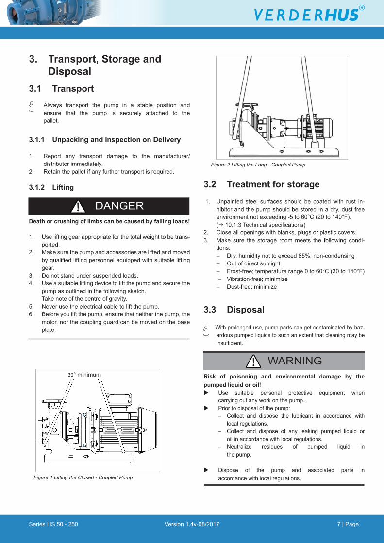
Figure 1 Lifting the Closed - Coupled Pump
3. Transport, Storage and Disposal3.1 Transport Always transport the pump in a stable position and ensure that the pump is securely attached to the pallet.
3.1.1 Unpacking and Inspection on Delivery
1. Report any transport damage to the manufacturer/ distributor immediately.2. Retainthepalletifanyfurthertransportisrequired.
3.1.2 Lifting
Death or crushing of limbs can be caused by falling loads!
1. Use lifting gear appropriate for the total weight to be trans-ported.
2. Make sure the pump and accessories are lifted and moved byqualifiedliftingpersonnelequippedwithsuitableliftinggear.
3. Do not stand under suspended loads.4. Use a suitable lifting device to lift the pump and secure the
pump as outlined in the following sketch. Take note of the centre of gravity.5. Never use the electrical cable to lift the pump.6. Before you lift the pump, ensure that neither the pump, the
motor, nor the coupling guard can be moved on the base plate.
3.2 Treatment for storage
1. Unpainted steel surfaces should be coated with rust in-hibitor and the pump should be stored in a dry, dust free environment not exceeding -5 to 60°C (20 to 140°F). (g10.1.3Technicalspecifications)
2. Close all openings with blanks, plugs or plastic covers.3. Make sure the storage room meets the following condi-
tions: – Dry, humidity not to exceed 85%, non-condensing – Out of direct sunlight – Frost-free; temperature range 0 to 60°C (30 to 140°F)
– Vibration-free;minimize – Dust-free;minimize
3.3 Disposal
Withprolongeduse,pumppartscangetcontaminatedbyhaz-ardouspumpedliquidstosuchanextentthatcleaningmaybeinsufficient.
Risk of poisoning and environmental damage by the pumped liquid or oil!u Use suitable personal protective equipment when carrying out any work on the pump.u Prior to disposal of the pump: – Collect and dispose the lubricant in accordance with local regulations. – Collect and dispose of any leaking pumped liquid or oil in accordance with local regulations. – Neutralize residues of pumped liquid in the pump.
u Dispose of the pump and associated parts in accordance with local regulations.
WARNING
DANGER
30° minimum
Figure 2 Lifting the Long - Coupled Pump
Series HS 50 - 250 Version 1.4v-08/2017 8 | Page
4. Layout and Function Verderhus® screw-channel pumps can transport numerous types of slurry and sludge with minimal wear, thanks to a large, open impeller based on the working principle of a corkscrew. The suction port is a large inlet of at least 50 mm (2 in) which allows the easy passage of pulverized and intact solids. Thewideflowpath is insusceptible toclogging,ragging and when pumping long fibrous fluids. The Verderhus® range of screw channel pumps is available in several different inlet sizes, ranging from 50 -250 mm (2-10 in).
4.1 Design Details
The Verderhus® range of screw channel pump has an open channel impeller design. Because of the combination of an open channel and the centrifugal forces high flow rates and efficiencies are accomplished.
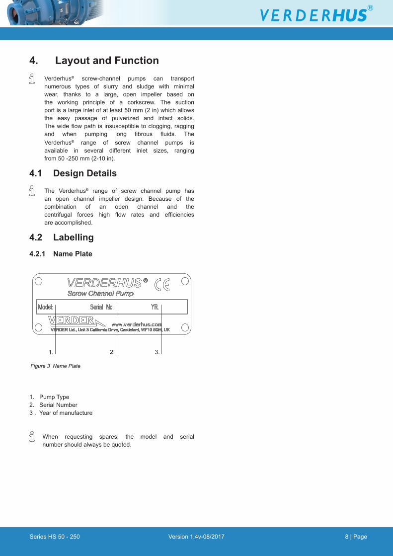
4.2 Labelling4.2.1 Name Plate
1. Pump Type 2. Serial Number3 . Year of manufacture
When requesting spares, the model and serial numbershouldalwaysbequoted.
1. 3.2.
Figure 3 Name Plate
Series HS 50 - 250 Version 1.4v-08/2017 9 | Page
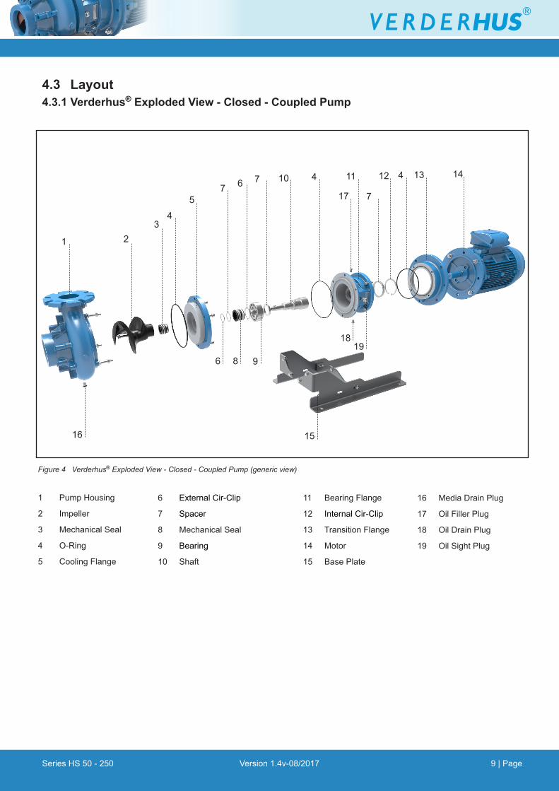
Figure 4 Verderhus® Exploded View - Closed - Coupled Pump (generic view)
1
4.3 Layout4.3.1 Verderhus® Exploded View - Closed - Coupled Pump
4
15
75
198
3
16
46
9
7 10 11
7
12 4 13 14
2
6
18
17
1 Pump Housing
2 Impeller
3 Mechanical Seal
4 O-Ring
5 Cooling Flange
16 Media Drain Plug
17 Oil Filler Plug
18 Oil Drain Plug
19 Oil Sight Plug
6 External Cir-Clip
7 Spacer
8 Mechanical Seal
9 Bearing
10 Shaft
11 Bearing Flange
12 Internal Cir-Clip
13 Transition Flange
14 Motor
15 Base Plate

Series HS 50 - 250 Version 1.4v-08/2017 10 | Page
Figure 5 Verderhus® Exploded View - Long - Coupled Pump (generic view)
1 Pump Housing
2 Impeller
3 Mechanical Seal
4 O-Ring
5 Cooling Flange
6 External Cir-Clip
1 4 6
19
4
2
5
47 18
20
23
10
22
7
13 1415
4 4
17
16
19 Base Plate
20 Media Drain Plug
21 Oil Filler Plug
22 Oil Drain Plug
23 Oil Sight Plug
7 Spacer
8 Mechanical Seal
9 Bearing
10 Drive
11 Bearing Flange
12 Internal Cir-Clip
13 Extended Bearing Housing
14 Cover Plate
15 Labyrinth Ring
16 Coupling Guard
17 Coupling
18 Motor
4.4 Lubrication
u Bearing housing: To be filled at installation withappropriatelubricantifnotsuppliedprefilled. (g10.1.5 Oil and Grease)
4.3.2 Verderhus® Exploded View - Long - Coupled Pump
21
3
8 9
6 7
11 9
12
6
Series HS 50 - 250 Version 1.4v-08/2017 11 | Page
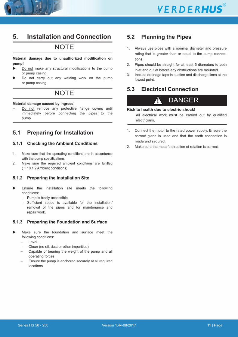
5. Installation and Connection
Material damage due to unauthorized modification on pump!u Do not make any structural modifications to the pump or pump casingu Do not carry out any welding work on the pump or pump casing
Material damage caused by ingress!– Do not remove any protective flange covers until immediately before connecting the pipes to the pump
5.1 Preparing for Installation
5.1.1 Checking the Ambient Conditions
1. Make sure that the operating conditions are in accordance withthepumpspecifications2. Make sure the required ambient conditions are fulfilled (g 10.1.2 Ambient conditions)
5.1.2 Preparing the Installation Site
u Ensure the installation site meets the following conditions: – Pump is freely accessible – Sufficient space is available for the installation/ removal of the pipes and for maintenance and repair work.
5.1.3 Preparing the Foundation and Surface
u Make sure the foundation and surface meet the following conditions:
– Level– Clean (no oil, dust or other impurities)– Capable of bearing the weight of the pump and all
operating forces– Ensurethepumpisanchoredsecurelyatallrequired
locations
NOTE
NOTE
5.2 Planning the Pipes
1. Always use pipes with a nominal diameter and pressure rating that isgreater thanorequal to thepumpconnec-tions.
2. Pipes should be straight for at least 5 diameters to both inlet and outlet before any obstructions are mounted.
3. Include drainage taps in suction and discharge lines at the lowest point.
5.3 Electrical Connection
Risk to health due to electric shock! All electrical work must be carried out by qualified electricians.
1. Connect the motor to the rated power supply. Ensure the correct gland is used and that the earth connection is made and secured.
2. Make sure the motor’s direction of rotation is correct.
DANGER
Series HS 50 - 250 Version 1.4v-08/2017 12 | Page
6. Commissioning and Operation
Start-up is not permitted until such time as the pump and all associated and connected devices have been installed and checked, and the safety officer has given the go-ahead foroperation to commence.
Pumped MediumThepumpmayonlybeoperatedusing themediumspecifiedin the data sheet. The materials used to build the pump are compatible with this medium.
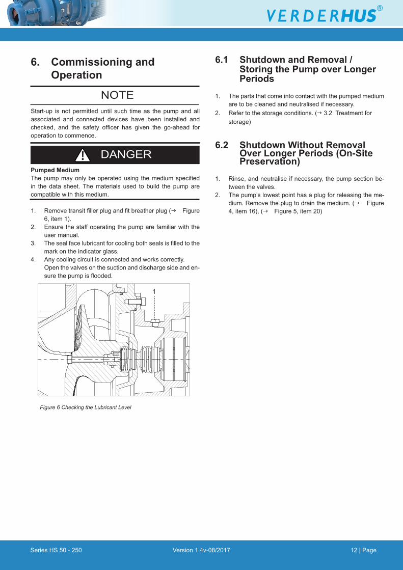
1. Removetransitfillerplugandfitbreatherplug(g Figure 6, item 1).
2. Ensure the staff operating the pump are familiar with the user manual.
3. Thesealfacelubricantforcoolingbothsealsisfilledtothemark on the indicator glass.
4. Any cooling circuit is connected and works correctly. Open the valves on the suction and discharge side and en-surethepumpisflooded.
DANGER
NOTE
6.1 Shutdown and Removal / Storing the Pump over Longer Periods
1. The parts that come into contact with the pumped medium are to be cleaned and neutralised if necessary.
2. Refer to the storage conditions. (g 3.2 Treatment for storage)
6.2 Shutdown Without Removal Over Longer Periods (On-Site Preservation)
1. Rinse, and neutralise if necessary, the pump section be-tween the valves.
2. The pump’s lowest point has a plug for releasing the me-dium. Remove the plug to drain the medium. (g Figure 4, item 16), (g Figure 5, item 20)
Figure 6 Checking the Lubricant Level
1

Series HS 50 - 250 Version 1.4v-08/2017 13 | Page
7. Inspection, Maintenance and Repairs
Risk of injury due to running pump!u Do not carry out any repair/maintenance work
on a pump whilst running.u Follow the safety procedures for handling the product
being pumped. u Decontaminate before handling as per local safety
regulations. u Appropriate measures must be taken to relieve any
pressure build up.
Risk of electrocution!u Have all electrical work carried out only by qualified electricians.
7.1 Inspections
The inspection intervals depend on the pump operating cycle.
1. Check at appropriate intervals: – No changes in operating conditions
2. For trouble-free operation, always ensure the following: – No leaks – No unusual running noises or vibrations – Lubricant level (g Figure 4 Checking the Lubricant Level) – Temperature is stable
7.2 Maintenance
VERDER LTD offers customers a service contract, whichcovers maintenance and repairs to the pump. ContactCustomerService,torequestanon-bindingoffer.
7.2.1 Cleaning the Pump
Make sure that no cleaning agent contaminates thepump bearings and motor.
u Cover all parts that should not come into contact with cleaning agent.
u Neverspraycoldliquidssuchaswateronhotpumpparts.The casing may crack if it cools too quickly, and mayrender the pump unusable.
DANGER
DANGER
ContactVERDERLTD.beforeyouusealiquidcleaningagent,andconfirmthattheproductthatyouintendtouseissafe.The operator must ensure that the product is safe to use with the pumped medium.
u Select a suitable method for cleaning the electrical material, andconsultaqualifiedelectrician.
7.3 Repair
Risk of death due to electric shock!u Haveallelectricalworkcarriedoutbyqualifiedelectrician
only.
Risk of injury due to heavy components!u Pay attention to the component weight. Lift and transport
heavy components using suitable lifting gear. u Set down components safely and secure them against
overturning or rolling away.
7.3.1 Returning the Pump to the Manufacturer
Obtain prior authorization before repair or return of the pump.u Enclose a completed document of compliance when
returning pumps or components to the manufacturer.
7.4 Ordering Spare Parts For trouble-free replacement in the event of faults, we
recommend keeping spare parts available on site.
u The following information is mandatory when ordering spare parts (g Name plate): – Pump model – Year of manufacture – Partnumber/Descriptionofpartrequired – Serial number – Quantity
NOTE
DANGER
WARNING
Series HS 50 - 250 Version 1.4v-08/2017 14 | Page
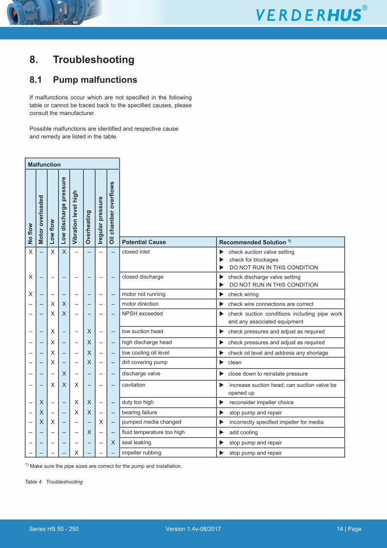
8. Troubleshooting
8.1 Pump malfunctions
Ifmalfunctionsoccurwhicharenot specified in the followingtableorcannotbetracedbacktothespecifiedcauses,pleaseconsult the manufacturer.
Possiblemalfunctionsareidentifiedandrespectivecauseand remedy are listed in the table.
Malfunction
No
flow
Mot
or o
verlo
aded
Low
flow
Low
dis
char
ge p
ress
ure
Vibr
atio
n le
vel h
igh
Ove
rhea
ting
Iregu
lar p
ress
ure
Oil
cham
ber o
verfl
ows
Potential Cause Recommended Solution 1)
X – X X – – – – closed inlet u check suction valve setting u check for blockages u DO NOT RUN IN THIS CONDITION
X – – – – – – – closed discharge u check discharge valve setting u DO NOT RUN IN THIS CONDITION
X – – – – – – – motor not running u check wiring
– – X X – – – – motor direction u check wire connections are correct
– – X X – – – – NPSH exceeded u check suction conditions including pipe work andanyassociatedequipment
– – X – – X – – low suction head u checkpressuresandadjustasrequired
– – X – – X – – high discharge head u checkpressuresandadjustasrequired
– – X – – X – – low cooling oil level u check oil level and address any shortage
– – X – – X – – dirt covering pump u clean
– – – X – – – – discharge valve u close down to reinstate pressure
– – X X X – – – cavitation u increase suction head; can suction valve be opened up
– X – – X X – – duty too high u reconsider impeller choice
– X – – X X – – bearing failure u stop pump and repair
– X X – – – X – pumped media changed u incorrectlyspecifiedimpellerformedia
– – – – – X – – fluidtemperaturetoohigh u add cooling
– – – – – – – X seal leaking u stop pump and repair
– – – – X – – – impeller rubbing u stop pump and repair
Table 4 Troubleshooting
1)Makesurethepipesizesarecorrectforthepumpandinstallation.

Series HS 50 - 250 Version 1.4v-08/2017 15 | Page
9. List of Figures and Tables 9.1 List of FiguresFigure 1 Lifting the Closed - Coupled Pump 3.1.2
Figure 2 Lifting the Long - Coupled Pump 3.1.2
Figure 3 Name Plate 4.2.1
Figure 4 Verderhus® Exploded View -
Closed Coupled Pump (generic view) 4.3.1
Figure 5 Verderhus® Exploded View -
Long Coupled Pump (generic view) 4.3.2
Figure 6 Checking the Lubricant Level 6
9.2 List of TablesTable 1 Target Groups 1.1
Table 2 Warnings Used in the Manual 1.2
Table 3 Symbols Used in the Manual 1.2
Table 4 Troubleshooting 9
Table5 PumpRangeSpecifications 10.1.1
Table6 PumpFastenerTighteningTorques 10.1.3
Table 7 Recommended Lubricants 10.1.5
Table 8 Declaration of Conformity 11
Series HS 50 - 250 Version 1.4v-08/2017 16 | Page
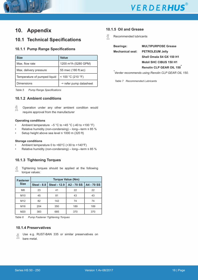
10. Appendix10.1 Technical Specifications
10.1.1 Pump Range Specifications
10.1.2 Ambient conditions
Operation under any other ambient condition would requireapprovalfromthemanufacturer
Operating conditions • Ambient temperature –5 °C to +45 °C (-40 to +100 °F)• Relativehumidity(non-condensing)–long—term≤85%• Setupheightabovesealevel≤1000m(320ft) Storage conditions • Ambient temperature 0 to +60°C (+30 to +140°F) • Relativehumidity(non-condensing)–long—term≤85%
10.1.3 Tightening Torques
Tightening torques should be applied at the followingtorquevalues:
10.1.4 Preservatives Use e.g. RUST-BAN 335 or similar preservatives on bare metal.
Table 5 Pump Range Specifications
Size Value
Max.flowrate 1200 m3/h (5280 GPM)
Max. delivery pressure 55 mwc (180 ft.wc)
Temperatureofpumpedliquid < 100 °C (210 °F)
Dimensions g refer pump datasheet
10.1.5 Oil and Grease
Recommended lubricants
Bearings: MULTIPURPOSE Grease
Mechanical seal: PETROLEUM Jelly
Shell Omala S4 GX 150 H1
Mobil SHC CIBUS 150 H1
Renolin CLP GEAR OIL 150*
*Verder recommends using Renolin CLP GEAR OIL 150.
Table 7 Recommended Lubricants
Fastener Size
Torque Value (Nm)
Steel - 8.8 Steel - 12.9 A2 - 70 SS A4 - 70 SS
M8 23 41 22 22
M10 45 81 43 43
M12 82 142 74 74
M16 204 350 189 189
M20 383 685 370 370
Table 6 Pump Fastener Tightening Torques

Series HS 50 - 250 Version 1.4v-08/2017 17 | Page
Table 8 Declaration of Conformity
EC declaration of conformity according to machine directive, appendix II A
We,
VERDER Ltd., Unit 3 California Drive, Castleford
hereby declare that the following machine adheres to the relevant EC directives detailed below:
Designation Type series HS 50-250
Description of product HUS-screw channel pumps for all liquids
under the pourpoint
EC directive:
• Machine Directive (2006/42/EC)
Applicableharmonizednorms:
• EN ISO 12100: 2010
• BS EN 809
Manufacturer VERDER Ltd. Unit 3 California Drive Castleford WF10 5QH UK
Date: 01/ 08/ 2017 Company stamp / signature:
Ben Allmond Head of Development/Construction
Company stamp / signature:
David Hoyland Head of Quality
11. Declaration of Conformity