scriber manual - nihal joshua's...
TRANSCRIPT


Scriber Manual
1
Table of Contents
Introduction.............................................................................................2
Lathe Machine.........................................................................................3
Milling Machine......................................................................................5
Drill Press................................................................................................7
Safety.......................................................................................................9
Drawings................................................................................................11
Dimensioning.........................................................................................14
Methods of Machining...........................................................................16
Conclusion.............................................................................................18
Scriber Manual
2
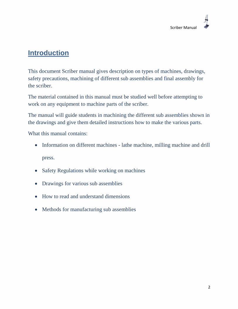
Introduction
This document Scriber manual gives description on types of machines, drawings, safety precautions, machining of different sub assemblies and final assembly for the scriber.
The material contained in this manual must be studied well before attempting to work on any equipment to machine parts of the scriber.
The manual will guide students in machining the different sub assemblies shown in the drawings and give them detailed instructions how to make the various parts.
What this manual contains:
• Information on different machines - lathe machine, milling machine and drill
press.
• Safety Regulations while working on machines
• Drawings for various sub assemblies
• How to read and understand dimensions
• Methods for manufacturing sub assemblies
Scriber Manual
3
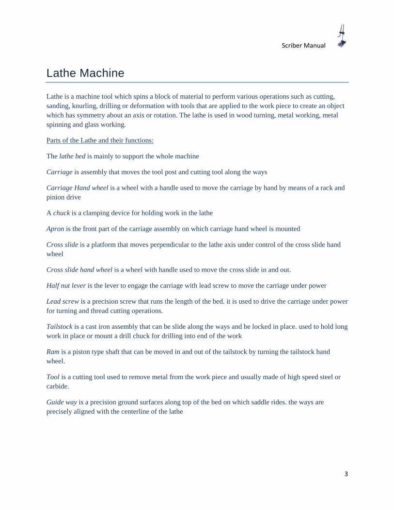
Lathe Machine
Lathe is a machine tool which spins a block of material to perform various operations such as cutting, sanding, knurling, drilling or deformation with tools that are applied to the work piece to create an object which has symmetry about an axis or rotation. The lathe is used in wood turning, metal working, metal spinning and glass working.
Parts of the Lathe and their functions:
The lathe bed is mainly to support the whole machine
Carriage is assembly that moves the tool post and cutting tool along the ways
Carriage Hand wheel is a wheel with a handle used to move the carriage by hand by means of a rack and pinion drive
A chuck is a clamping device for holding work in the lathe
Apron is the front part of the carriage assembly on which carriage hand wheel is mounted
Cross slide is a platform that moves perpendicular to the lathe axis under control of the cross slide hand wheel
Cross slide hand wheel is a wheel with handle used to move the cross slide in and out.
Half nut lever is the lever to engage the carriage with lead screw to move the carriage under power
Lead screw is a precision screw that runs the length of the bed. it is used to drive the carriage under power for turning and thread cutting operations.
Tailstock is a cast iron assembly that can be slide along the ways and be locked in place. used to hold long work in place or mount a drill chuck for drilling into end of the work
Ram is a piston type shaft that can be moved in and out of the tailstock by turning the tailstock hand wheel.
Tool is a cutting tool used to remove metal from the work piece and usually made of high speed steel or carbide.
Guide way is a precision ground surfaces along top of the bed on which saddle rides. the ways are precisely aligned with the centerline of the lathe
Scriber Manual
4
Lathe Machine

Scriber Manual
5
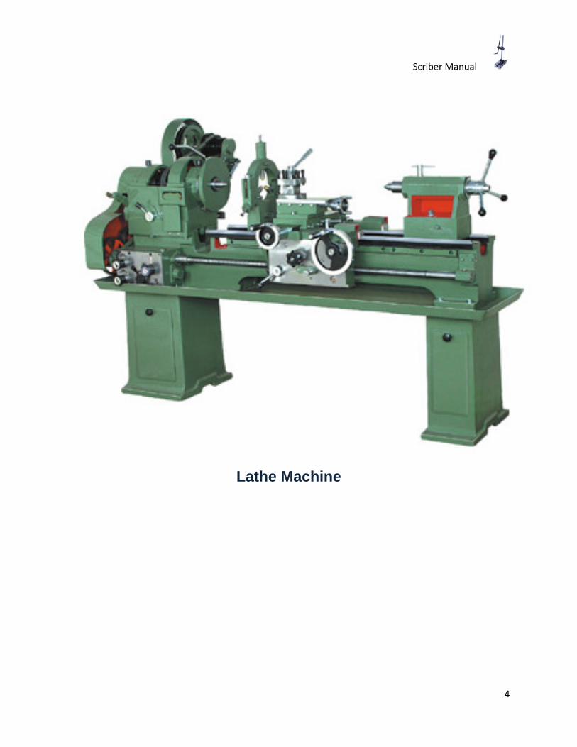
Milling Machine
Milling machines are used to shape solid products by eliminating excess material in order to form a finished product. Milling machines can be used for a variety of complicated cutting operations – from slot cutting, threading, and drilling.
A milling machine is usually capable of cutting a wide variety of metals, ranging from aluminum to stainless steel. Depending on the material being cut, the machine can be set to move at a faster or slower pace. Softer materials are generally milled at higher speeds while harder materials usually require slower speeds. In addition, harder materials often require smaller amounts of material to be milled off at one time.
Generally, a milling machine operator runs the machine by feeding the material over a device called a milling cutter. As the material is fed past the cutter, the cutter’s teeth slice through the material to form the desired shape. Using gadgets like precision ground slides and lead screws, the movement of the material as well as the cutter can be kept very low in order to make the cut exact.
A typical mill machine contains a spindle axis, which is a device that holds the cutter in place. The cutter revolves around the spindle axis, and the axis can usually be adjust to varying speeds. Most machines also come with a worktable that can be used to support and feed the material. The worktable generally moves in two directions, and most modern worktables are power-operated. Additionally, a modern milling machine is typically equipped with a self-contained electric drive motor and a coolant system.
From micro, mini, and bench top to floor standing, large, and gigantic, a milling machine can be found in a variety of sizes. Milling machines can have flat, angular, curved, or irregular surfaces. In addition, they can have a vertical or a horizontal orientation. A vertical milling machine has a spindle axis that faces vertically while a horizontal machine’s spindle faces horizontally.
Milling machinery can be operated manually or digitally and the traditional X, Y, and Z axes are found in a manual machine.
Scriber Manual
6
Milling Machine
Scriber Manual
7
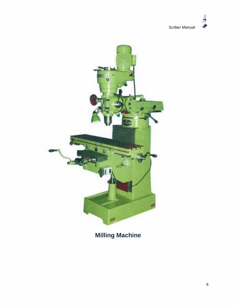
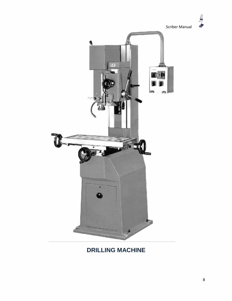
Drill Press
The drill is a staple in the arsenal of woodworkers, carpenters, and machinists for many years, and the versatility of the drill has only increased in recent decades. When accuracy is key to success, professionals will turn to a drill press, or a vertical drill that is fixed to a tabletop, workbench, or to the floor. The drill press also known as a bench drill is capable of drilling accurately spaced holes at specific depths, widths, and straightness.
This tool is composed of a base, column, spindle, and drill head. The base is a tabletop or it can be built-in legs made of metal; every drill press includes a table, or a surface to rest the materials to be drilled. It is positioned below the drill spindle and head, which spin and hold the bit respectively. A bench drill press is smaller and more portable, but a floor model is typically more powerful and has more accessory options.
The drill press has a three-armed handle attached to the head that raises and lowers the drill bit. These arms give the user more control over the movement of the bit and enhance ease of use. A depth-stop may be used to prevent the bit from moving past a certain point, therefore allowing the user to make uniform-depth holes in various locations on whatever material is to be drilled.
The size of the drill press is determined by measuring the distance from the drill head chuck to the column; this measurement is doubled to determine the drill press's size. For example, if the measurement between the center of the chuck to the column is eight inches, then the drill press is considered a sixteen inch drill press. This is so because while the press can drill a hole eight inches from the side of a straight board, it can drill into the center of a sixteen inch circle; hence, the largest diameter of board the press can handle is sixteen inches.
A drill press is typically motor-driven and variable speed, which means the user has to expend less effort in using the drill press than in hand drilling. The variable speed allows the user to use the drill press for a variety of tasks, from drilling holes to sanding materials. The variable speed also allows the user to control the amount of force and friction on the drill bit, thereby preventing unnecessary wear or breakage.
Scriber Manual
8
DRILLING MACHINE
Scriber Manual
9
Safety Regulations
1. All students are required to purchase their own eye protection, which is to be worn at all times while in the laboratory.
2. Suitable footwear has non slip soles and hard uppers which completely enclose the foot. Sandals are inappropriate.
3. It is strongly advised that jewelry not be worn on fingers or wrists while working on or around the machine.
4. Long, loose hair must be constrained to prevent engagement in moving machinery, tools work etc.
5. Neckties, necklaces and other similar items must be removed or tucked into the shirt to prevent engagement in moving machinery, tools, work etc.
6. Compressed air may be used to clean parts and small tools only during designated laboratory work periods. Compressed air may under no circumstances be used during clean up periods, nor to clean machinery, clothing or any part of one's body.
7. Consult with the instructor prior to attempting to lift or move heavy objects.
8. One student only may operate a machine tool at a given time.
9. Metal chips may be removed with a brush, never use fingers.
10. Non essential conversation with students operating machinery is prohibited.
11. Do not stop or slow revolving tools, chucks or work using fingers or hands.
12. Unusual machine setups must be approved by the instructor prior to machining.
13. Only official assignments may be undertaken during laboratory periods.
14. Any liquid spills are to be wiped up immediately.
15. Running and any horseplay are expressly forbidden
16. Only officially enrolled students may enter and work in the laboratory
17. No food or beverages are permitted in the laboratory.
Scriber Manual
10
18. Machine guards/safety devices may not be removed or rendered inoperative.
19. Equipment with faulty guards/safety devices should not be used.
20. Personal audio/visual devices, including cell phones, will not be used in the laboratory.
21. Students with hidden medical conditions or handicaps, which may impact on their safe functioning in the laboratory are requested to consult with the instructor.
22. Any accident regardless of severity will be reported promptly to the instructor.
Scriber Manual
11
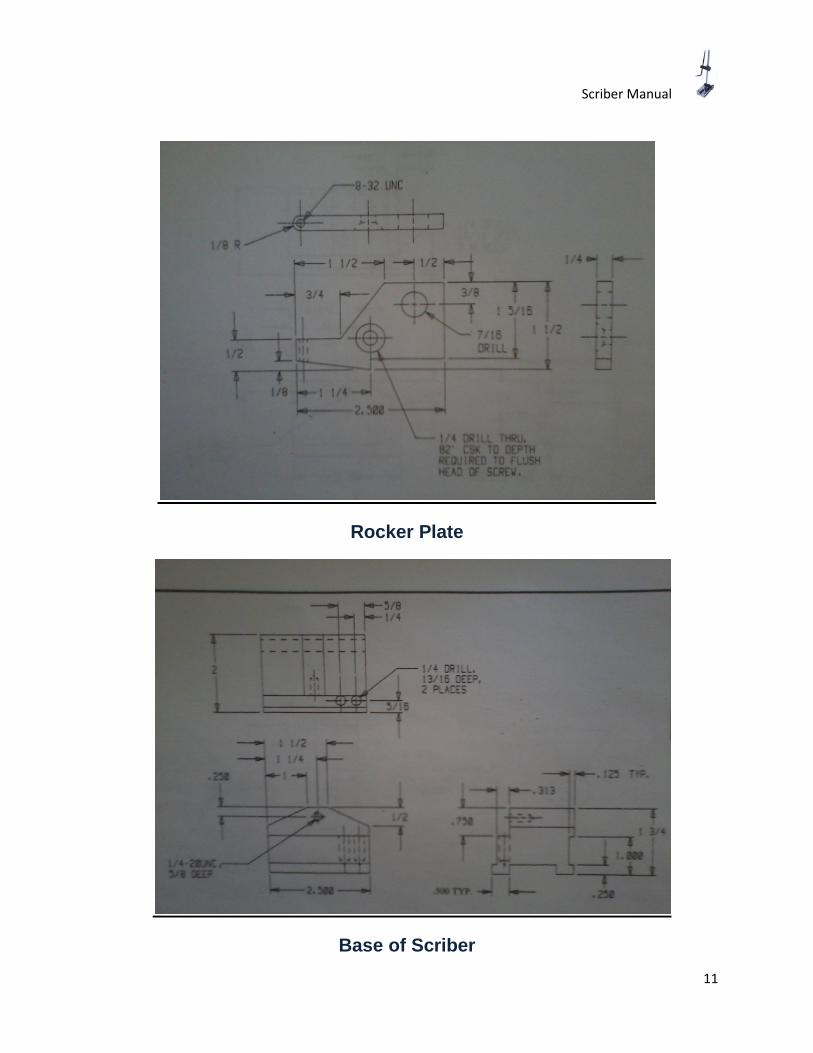
Rocker Plate
Base of Scriber
Scriber Manual
12
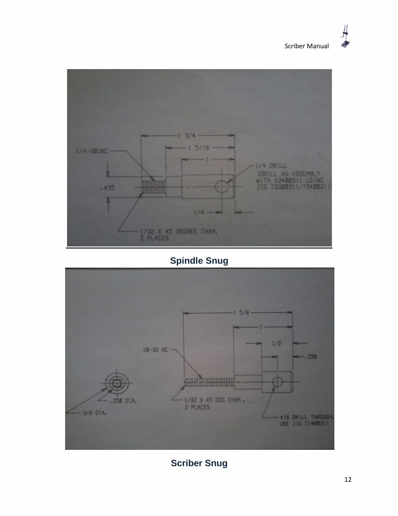
Spindle Snug
Scriber Snug
Scriber Manual
13
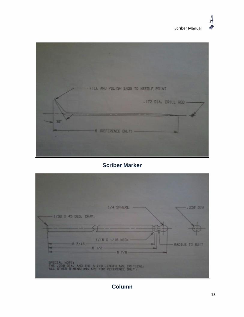
Scriber Marker
Column

Scriber Manual
14
Dimensioning Fundamentals
Dimension lines: Lines located between extension lines ending with an arrow and to include a numerical value. They should be spaced uniformly approximately .375 to .500 inches apart.
Extension lines: Extend away from a view to indicate a size or location constraint origin. When extension lines cross object or extension lines, no gap in either line should be made.
Leader Lines: Lines drawn at an angle (never horizontal or vertical) extending from a note to a feature to which the note applies.
Dimension and Extension line placement
1. Always place shorter dimensions nearest to the object lines. Dimension lines should never cross. However, extension lines may cross each other.
Scriber Manual
15
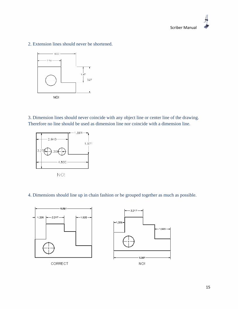
2. Extension lines should never be shortened.
3. Dimension lines should never coincide with any object line or center line of the drawing. Therefore no line should be used as dimension line nor coincide with a dimension line.
4. Dimensions should line up in chain fashion or be grouped together as much as possible.
Scriber Manual
16
Methods for Machining
1. Rocker Plate
The rocker plate comes as a rough piece of raw material. You need to debur it with a file and then square it to the size 2.5 x 1.5 inches with a 1 inch tool on a milling machine. Once the sides are squared apply dykem on one side of the work piece. Once the dykem dries off, mark the measurements with a scriber marker on the rocker plate. Also mark the holes to be drilled with a centre punch. Once the markings are done you need to drill the holes, since the sides of the plate help to grip the work piece in the vice. The centre punched holes need to be first drilled with a no. 2 center drill and then a 1/4" drill. Then the hole marked 7/16 needs to be drilled with a 7/16 drill bit and the counter sunk hole needs to be drilled with a counter sunk 82' x 3/4 countersunk tool. Once the holes are drilled cut out the major portion of the to be machined portion with the hacksaw and give the finishing on a 2inch cutting tool milling machine giving low depths of cut of ten thousands of an inch.
2. Scriber Base
The sides of the base are irregular and need to be smoothened out by machining with a 2 inch tool on a milling machine and then need to be squared to the size 2.5 x 2 inches. Once the sides are squared you need to place the work piece on a marking table and apply dykem on the face that is 2 inches long. Once the dykem dries off you mark with a scriber marker as per the drawing shown. The slant edges need to be machined with a 2 inch cutting tool. The slot on the base should be cut with a 1 inch cutting tool and all other slots should be cut with the 3/4 inch cutting tool. For all slots, each depth of cut should be fifteen thousand per cut. Once all sides are machined, you apply dykem and mark the faces for the holes that need to be drilled and tapped as per the drawing shown. Follow the same procedure of marking as mentioned above and once that is done, drill the plunger holes with 1/4 inch drill bit. The centre hole first needs to be drilled with a center drill no. 3 followed by a drill size no. 8 and then should be tapped with a taper tap size (1/4 -20 UNC) followed by a bottoming tap of the same size. Do not forget to oil while tapping the hole.

Scriber Manual
17
3. Spindle Snug
The raw material for spindle snug is rough and irregular. You need to face it on a lathe machine. For the facing operation you need to swivel the tool post to approximately twenty degrees. Once you face one side, you flip the side over on the lathe and face the other end. You mark the measurements on the bar using a little dykem and a scriber marker. Once the markings are done you swivel the tool post to zero and bring the bar to the appropriate diameter. Once you have machined the bar to the right size, you do complete the threading operation with the help of a die stock size (1/4 - 20 UNC). The threading is done taking the support of the tailstock. Once the die stock is set on the work piece, you move the tailstock handle in the clockwise direction and the chuck in the anti clockwise direction. Once the threading operation is complete, you chamfer both ends of the bar using a file, holding it at an angle 45 degrees.
4. Scriber Snug
The raw material for scriber snug is rough and irregular and so you need to face it on a lathe machine. The operation for the scriber snug is exactly the same as spindle snug, but you need to give it a very low depth of cut. For the facing operation you need to swivel the tool post to approximately twenty degrees. Once you face one side, you flip the side over on the lathe and face the other end. You mark the measurements on the bar using a little dykem and a scriber marker. Once the markings are done you swivel the tool post to zero and bring the bar to the appropriate diameter. Once you have machined the bar to the right size, you do complete the threading operation with the help of a die stock size (10 - 32 UNC). The threading is done taking the support of the tailstock. Once the die stock is set on the work piece, you move the tailstock handle in the clockwise direction and the chuck in the anti clockwise direction. Once the threading operation is complete, you chamfer both ends of the bar using a file, holding it at an angle 45 degrees.
5. Scriber
The scriber raw material is made of drill rod and is soft enough to be sharpened with a file. Set up the scriber on a lathe with a collet chuck and hold it about three quarters inside the chuck and just about a quarter outside. Keep filing till you get a sharp pointed end on both sides. Once the ends are sharpened you insert the scriber into a bending tool about a quarter inch inside and bend it.
6. Column
The column does not have a specific machining operation. You have to size the column to the required length by mounting it on a vice and cutting with a hacksaw blade. Once it is to length you face both ends and chamfer with a file to angle of forty five degrees.

Scriber Manual
18
Conclusion
In the course of the manual we have discussed the various machines that are being used in machining the scriber. The manual describes how the machines operate and it gives a fair idea how an operator should operate it. The manual also lists the safety precautions that one should follow while on a shop floor, operating a machine. The manual teaches fundamentals of drawing and in a way that is understood by students. This is followed by drawings of the scriber in either one view or three different views. The last part of the manual explains the detailed machining process of each part to be machined.