section 23 52 39.01 fire tube boiler burner part 1
TRANSCRIPT
05-02-18
23 52 39 - 1
SECTION 23 52 39.01
FIRE TUBE BOILER BURNER
PART 1 - GENERAL
1.1 DESCRIPTION
A. This section specifies packaged fire tube boiler trim (accessories),
dual fuel (natural gas and No. 2 oil) burner, fuel valve and piping
trains, and other accessories.
B. A complete listing of common acronyms and abbreviations are included in
Section 23 05 10, COMMON WORK RESULTS FOR BOILER PLANT AND STEAM
GENERATION.
1.2 RELATED WORK
A. Section 01 00 00, GENERAL REQUIREMENTS.
B. Section 01 33 23, SHOP DRAWINGS, PRODUCT DATA, AND SAMPLES.
C. Section 01 35 26, SAFETY REQUIREMENTS
D. Section 01 91 00, GENERAL COMMISSIONING REQUIREMENTS.
E. Section 13 05 41, SEISMIC RESTRAINT REQUIREMENTS FOR NON-STRUCTURAL
COMPONENTS.
F. Section 23 05 10, COMMON WORK RESULTS FOR BOILER PLANT AND STEAM
GENERATION.
G. Section 23 08 11, DEMONSTRATIONS AND TESTS FOR BOILER PLANT.
H. Section 23 05 51, NOISE AND VIBRATION CONTROLS FOR BOILER PLANT.
I. Section 23 09 11, INSTRUMENTATION AND CONTROL FOR BOILER PLANT.
J. Section 23 21 11, BOILER PLANT PIPING SYSTEMS.
K. Section 23 51 00, BREECHINGS, CHIMNEYS, AND STACKS.
L. Section 26 05 33, RACEWAY AND BOXES FOR ELECTRICAL SYSTEMS.
1.3 APPLICABLE PUBLICATIONS
A. The publications listed below form a part of this specification to the
extent referenced. The publications are referenced in the text by the
basic designation only. Where conflicts occur these specifications and
the VHA standard will govern.
B. ASTM International (ASTM):
A106/A106M-2015.........Standard Specification for Seamless Carbon
Steel Pipe for High-Temperature Service
A178/178M-2002 (R2012)..Standard Specification for Electric-Resistance-
Welded Carbon Steel and Carbon-Manganese Steel
Boiler and Superheater Tubes

05-02-18
23 52 39 - 2
A254-1997...............Standard Specification for Copper-Brazed Steel
Tubing
C612-2014...............Standard Specification for Mineral Fiber Block
and Board Thermal Insulation
D396-2015c..............Standard Specification for Fuel Oils
C. American Society of Mechanical Engineers (ASME):
B31.1-2014..............Power Piping
ASME Boiler and Pressure Vessel Code:
BPVC Section I-2015.....Rules for Construction of Power Boilers
BPVC Section II-2015....Materials
BPVC Section VII-2015...Recommended Guidelines for the Care of Power
Boilers
BPVC Section VIII-2015..Rules for Construction of Pressure Vessels
BPVC Section IX-2015....Welding, Brazing, and Fusing Qualifications
Performance Test Code (PTC):
PTC 4-2013..............Fired Steam Generators
D. Environmental Protection Agency (EPA):
CFR 40, PART 60, Appendix A,
Method 9-2017...........Visual Determination of the Opacity of
Emissions from Stationary Sources
E. National Fire Protection Association (NFPA):
85-2015.................Boiler and Combustion Systems Hazards Code
F. Department of Veterans Affairs (VA):
........................VHA Boiler Plant Safety Devices Testing Manual,
fourth Edition
1.4 SUBMITTALS
A. Submittals, including number of required copies, shall be submitted in
accordance with Section 01 33 23, SHOP DRAWINGS, PRODUCT DATA, AND
SAMPLES.
B. Information and material submitted under this section shall be marked
“SUBMITTED UNDER SECTION 23 52 39, FIRE TUBE BOILER BURNERS”, with
applicable paragraph identification.
C. Manufacturer's Literature and Data including: Full item description and
optional features and accessories. Include dimensions, weights,
materials, applications, standard compliance, model numbers, size, and
capacity.

05-02-18
23 52 39 - 3
D. Burner and Fuel Valve and Piping Trains:
1. Catalog data and drawings showing burner assembly and fuel train
arrangement.
2. Outline drawings of flue gas recirculation (FGR) ductwork (if
applicable).
3. Outline drawings of sound attenuators on forced draft fan intake or
discharge.
4. Drawings showing assembly of throat refractory into furnace and any
modifications required to the existing boiler and support details.
5. Type and temperature rating of throat refractory.
6. Drawings and catalog data on all equipment in igniter (pilot) train,
main fuel trains, and atomizing media train. Include data on
pressure and temperature ratings, flow versus pressure drop,
performance characteristics. Include complete data on air
compressors (for oil atomizing) with sound attenuators and motors.
7. ASTM numbers and schedule numbers on all piping.
8. Type and pressure ratings of pipe fittings.
9. Burner flow and pressure data:
a. Main burner fuel and atomizing air pressures and flows at maximum
required firing rate.
b. Igniter (pilot) fuel flow and burner pressure.
c. Natural gas main fuel pressure at inlet and outlet of main burner
pressure regulator.
d. Igniter (pilot) fuel pressures (natural gas and LP gas) at inlet
and outlet of burner-mounted pressure regulators.
e. Forced draft fan static pressure, power and air flow at maximum
firing rate.
f. Oil pressure required at boiler fuel oil pump inlet.
10. Full load efficiency and power factor of all motors.
11. Predicted sound level at maximum firing rate on each main fuel.
12. Weight of burner assembly.
13. Steps required to change from one fuel source to another.

05-02-18
23 52 39 - 4
E. Burner, Predicted Performance Data:
1. At Maximum Required Output: On each fuel at site altitude, with
economizer in service, at 15 percent excess air. Data must include
fuel and steam flow, boiler flue gas outlet temperature, economizer
flue gas outlet temperature, steam quality, boiler efficiency,
furnace pressures, and predicted boiler radiation and unaccounted
losses, feedwater and flue gas pressure losses in the economizer.
2. At low fire, 25 percent, 50 percent, and 75 percent of Maximum
Required Output. Excess air 15 percent, CO 50 ppm, 30 NOx ppm on
each fuel.
F. Schematic wiring diagram of boiler control system showing all
components, all interlocks, etc. Schematic wiring diagram shall clearly
identify factory wiring and field wiring and separation of the burner
control system from the Burner Management (Flame Safeguard Control)
system.
G. Pretest Data - Burner, Controls: As required by Part 3.
H. Complete operating and maintenance manuals including wiring diagrams,
technical data sheets, information for ordering replacement parts, and
troubleshooting guide:
1. Include complete list indicating all components of the systems.
2. Include complete diagrams of the internal wiring for each item of
equipment.
3. Diagrams shall have their terminals identified to facilitate
installation, operation and maintenance.
I. Completed System Readiness Checklist provided by the Commissioning
Agent and completed by the contractor, signed by a qualified technician
and dated on the date of completion,
J. Submit training plans and instructor qualifications, provided by the
contractor.
1.5 QUALITY ASSURANCE
A. Coordinate all new and existing equipment and conditions. This
includes, but is not limited to: existing boiler, burner, fuel valve
and piping trains, gas pressure regulators and available gas pressure,
required fuel oil train pressures and fuel oil header back pressure
regulator on house oil pump set, compressed air system for oil
atomization, existing control systems, existing breeching and stacks.
B. The model and size of the proposed burner shall have been applied to at
least three fire tube boilers which are similar in size, proportion,

05-02-18
23 52 39 - 5
number of passes and furnace dimensions to the proposed boiler. In each
of the three installations, burner performance shall have conformed to
requirements specified in the paragraph, BURNER AND FUEL TRAINS,
subparagraph, PERFORMANCE of this Section. Provide list of these
installations, and name, address, and telephone number of person
familiar with each project who will serve as a reference source.
C. Regardless of fuel input rating, the equipment, installation and
operation shall conform to NFPA 85. Where conflicts exist between NFPA
85 and this specification, this specification will govern.
1.6 AS-BUILT DOCUMENTATION
A. Submit manufacturer’s literature and data updated to include submittal
review comments and any equipment substitutions.
B. Submit operation and maintenance data updated to include submittal
review comments, VA approved substitutions and construction revisions
shall be in electronic version on CD or DVD inserted into a three-ring
binder. All aspects of system operation and maintenance procedures,
including applicable piping isometrics, wiring diagrams of all
circuits, a written description of system design, control logic, and
sequence of operation shall be included in the operation and
maintenance manual. The operations and maintenance manual shall include
troubleshooting techniques and procedures for emergency situations.
Notes on all special systems or devices shall be included. A List of
recommended spare parts (manufacturer, model number, and quantity)
shall be furnished. Information explaining any special knowledge or
tools the owner will be required to employ shall be inserted into the
As-Built documentation.
C. The installing contractor shall maintain as-built drawings of each
completed phase for verification; and, shall provide the complete set
at the time of final systems certification testing. Should the
installing contractor engage the testing company to provide as-built or
any portion thereof, it shall not be deemed a conflict of interest or
breach of the ‘third party testing company’ requirement. Provide record
drawings as follows:
1. As-built drawings are to be provided, with a copy of them on AutoCAD
version 2015 provided on CD or DVD. The CAD drawings shall use
05-02-18
23 52 39 - 6
multiple line layers with a separate individual layer for each
system.
D. The as-built drawings shall indicate the location and type of all
lockout/tagout points for all energy sources for all equipment and
pumps to include breaker location and numbers, valve tag numbers, etc.
Coordinate lockout/tagout procedures and practices with local VA
requirements.
E. Certification documentation shall be provided to COR, in 21 working
days prior to submitting the request for final inspection. The
documentation shall include all test results, the names of individuals
performing work for the testing agency on this project, detailed
procedures followed for all tests, and provide
documentation/certification that all results of tests were within
limits specified. Test results shall contain written sequence of test
procedure with written test results annotated at each step along with
the expected outcome or setpoint. The results shall include all
readings, including but not limited to data on device (make, model and
performance characteristics), normal pressures, switch ranges, trip
points, amp readings, and calibration data to include equipment serial
numbers or individual identifications, etc.
1.7 PROJECT CONDITIONS
A. Fuels to be Fired, Main Burner: Natural gas with fuel oil backup.
B. Igniter (Pilot) Fuels: Natural Gas and LP gas (propane).
C. Natural Gas: High heating value is reported as 1000 (Btu/cubic foot) at
gas company base pressure and temperature. Pressure provided to the
inlet of the boiler-mounted regulators will be 10 psig as maintained by
main regulator station.
D. Fuel Oil: Will be furnished under Government contract. House pumping
system is designed to provide 100 (psig) gauge nominal to the fuel
train entrance on each burner. Pressure will vary in accordance with
characteristics of backpressure regulator on oil pump set. Oil grade
(No. 2) refers to ASTM D396. No burner-mounted pump or relief valve is
allowed.
E. Oil Atomizing Media: Low-pressure air atomizing burners are required
and each boiler must include a dedicated air compressor system
furnished by burner manufacturer.
F. LP Gas: Propane furnished directly to the Government for igniter
(pilot) fuel by a local supplier. Regulators at tank area will be set
05-02-18
23 52 39 - 7
at 34 kPa (5 psig) gauge. Serves as igniter fuel when there is an
interruption to the natural gas supply.
PART 2 - PRODUCTS
2.1 BURNER AND FUEL TRAINS
A. Burner Type: Integral combination natural gas and fuel oil, packaged,
forced draft, modulating firing, and variable speed forced draft fan,
burner design must be gun type to mitigate high-furnace pressure.
Burner shall be manufactured and tested by the burner manufacturer on a
boiler similar to the existing unit specified herein.
1. Gas Burner: Ring type with multiple ports or spuds.
2. Oil Burner: Gun type, inside mix, low pressure air atomizing.
3. Igniter (Pilot): Interrupted, electrically ignited, natural gas and
propane.
4. Change of fuels will require the minimum of disassembly and
reassembly of the fuel train on burner fuel nozzles.
B. Service:
1. Continuous operation at all firing rates on each fuel listed under
paragraph, PROJECT CONDITIONS of this Section. Design the entire
burner and fuel train system for application to the specific boiler
furnished and for service at the available fuel pressures.
2. Igniter (Pilot) Fuels: Normal fuel will be natural gas. Propane will
be used if there is an interruption in natural gas service.
3. Main Fuels: Primary Fuel, Natural Gas; Secondary Fuel, No. 2 Diesel
C. Performance:
1. Igniter (pilot) flame on natural gas and propane shall form close to
the point of ignition and shall be stable. Ignite both the gas and
oil burner with single igniter.
2. Main flame on gas and oil fuels shall ignite at lowest firing rate.
3. Main flame characteristics at all firing rates:
a. Flame retained at the burner.
b. Flame stable with no blowoff from the burner or flashback into
the burner. Pulsations, rumble, or vibrations are prohibited at
any firing rate.
c. No deposits of unburned fuel or carbon at any location.
d. No carryover of flame beyond the end of the first pass (furnace
tube).
05-02-18
23 52 39 - 8
e. Steady constant direct contact or impingement of the flame on any
surface is prohibited.
4. Main Burner Operation:
a. Minimum turndown 10:1.
b. Operate at all loads on any one fuel without any manual changes
to burners, fuel trains or fuel pressures, atomizing media trains
or pressures.
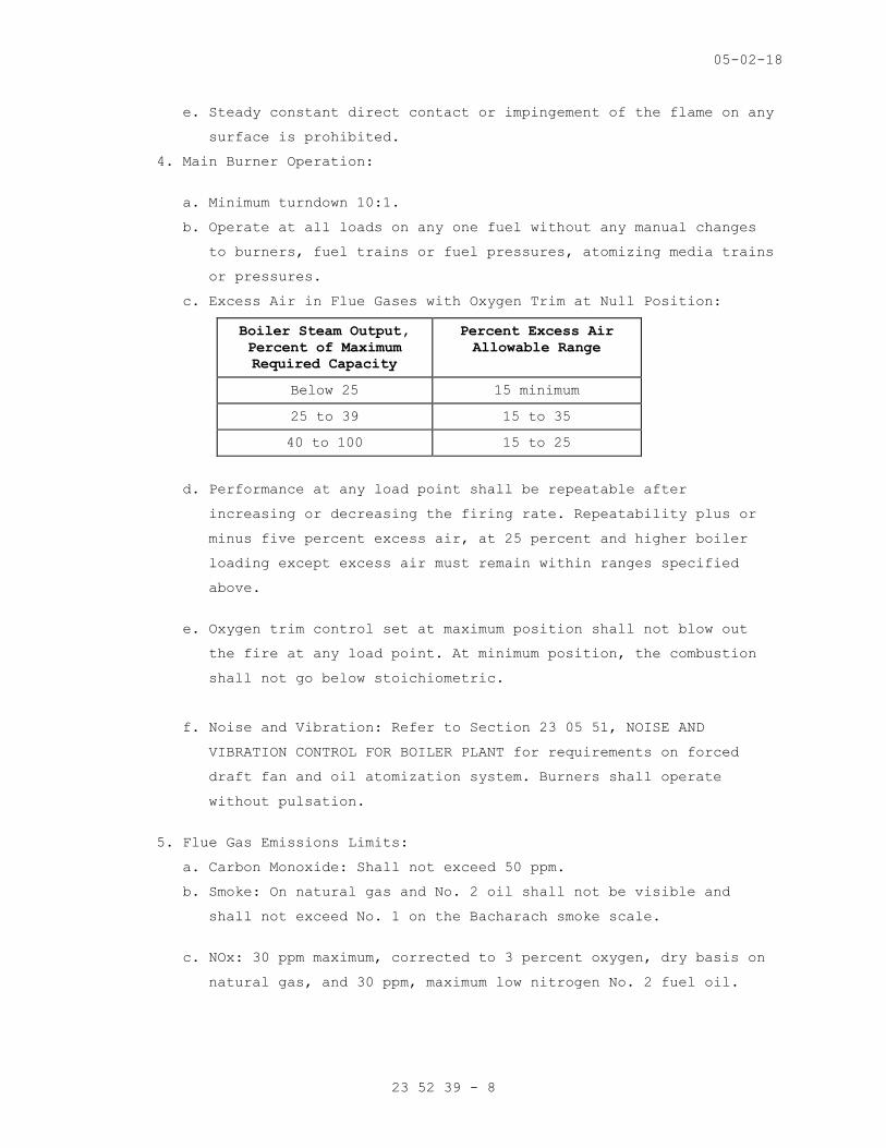
c. Excess Air in Flue Gases with Oxygen Trim at Null Position:
Boiler Steam Output,
Percent of Maximum
Required Capacity
Percent Excess Air
Allowable Range
Below 25 15 minimum
25 to 39 15 to 35
40 to 100 15 to 25
d. Performance at any load point shall be repeatable after
increasing or decreasing the firing rate. Repeatability plus or
minus five percent excess air, at 25 percent and higher boiler
loading except excess air must remain within ranges specified
above.
e. Oxygen trim control set at maximum position shall not blow out
the fire at any load point. At minimum position, the combustion
shall not go below stoichiometric.
f. Noise and Vibration: Refer to Section 23 05 51, NOISE AND
VIBRATION CONTROL FOR BOILER PLANT for requirements on forced
draft fan and oil atomization system. Burners shall operate
without pulsation.
5. Flue Gas Emissions Limits:
a. Carbon Monoxide: Shall not exceed 50 ppm.
b. Smoke: On natural gas and No. 2 oil shall not be visible and
shall not exceed No. 1 on the Bacharach smoke scale.
c. NOx: 30 ppm maximum, corrected to 3 percent oxygen, dry basis on
natural gas, and 30 ppm, maximum low nitrogen No. 2 fuel oil.

05-02-18
23 52 39 - 9
D. Construction:
1. Burner Access (Main Burner and Igniter): Arrange fuel valve and
piping trains, controls and other devices so that they do not
interfere with the removal and replacement of burner parts.
2. Arrangement of Fuel Valve and Piping Trains: All devices shall be
accessible for maintenance or replacement without removal of other
devices. Do not attach any piping or devices to boiler casings.
3. Coatings: Provide surface preparation, heat resistant prime and two
finish coats using standard color of boiler manufacturer.
4. Combustion Air System and Flue Gas Recirculation (FGR) System:
a. Air flow rates controlled by forced draft fan inlet or outlet
dampers and variable speed drive.
b. Symmetrical, balanced distribution of combustion air into the
burner.
c. Provide induced type FGR system if FGR is necessary to achieve
specified NOx limits. All FGR ductwork shall comply with Section
23 51 00, BREECHINGS, CHIMNEYS, AND STACKS.
d. Forced Draft Fan: Airfoil or backwardly inclined wheel, electric
motor driven. Design for required excess air and for static
pressure that is based on losses from fan inlet to stack or
chimney outlet, including economizer, at jobsite altitude. Fan
shall have no resonant frequencies at all operating speeds.
e. Motor: TEFC or open drip proof, non-overloading under all fan
operating conditions, design for 40 degrees C (104 degrees F)
ambient, premium efficiency type. Motors for variable speed
service shall be rated inverter-ready. Refer to Section 23 05 10,
COMMON WORK RESULTS FOR BOILER PLANT AND STEAM GENERATION.
f. Damper: Design to provide accurate control of excess air with
minimum hysteresis. On variable speed systems, the damper shall
operate across all firing rates.
g. Motor Starter Panel: Provide motor starter and variable speed
drive mounted in NEMA 4 enclosure, readily accessible. Refer to
Section 23 05 10, COMMON WORK RESULTS FOR BOILER PLANT AND STEAM
GENERATION. Refer to Section 23 09 11, INSTRUMENTATION AND
CONTROL FOR BOILER PLANT, for burner management system motor
power interlocks.

05-02-18
23 52 39 - 10
h. Sound Attenuators: Provide attenuators on forced draft air
intakes to reduce sound levels to allowable limits. Refer to
Section 23 05 51, NOISE AND VIBRATION CONTROL FOR BOILER PLANT.
5. Provide front and rear viewports, with one clear and one tinted
replaceable interchangeable glass. Locate to permit view of main and
igniter flames.
6. Burner Throat: Refractory tile, shaped to promote proper combustion,
arranged with provisions for expansion and contraction and rated by
the refractory manufacturer for the maximum service conditions.
7. Electrical Conduit: Provide liquid-tight flexible metal conduit with
sealing fittings for all power and control services to fuel trains
and burners. Flexible metal conduit must be limited to 900 mm (3
feet) in length, unless additional length is required for door or
burner swing. Refer to Section 26 05 33, RACEWAY AND BOXES FOR
ELECTRICAL SYSTEMS.
8. Factory Testing: Burner shall be factory tested across full
operating range, to provide data necessary for air quality permit
application.
E. Natural Gas Main Fuel Train:
1. Arrangement: Comply with typical arrangement in NFPA 85, Annex A, as
modified by the following description. Starting at the entrance to
the train, the devices are, in sequence: plug valve, filter,
pressure gauge, pressure regulator, valved connection to pilot
burner fuel train, flow meter (if required), pressure gauge, low
pressure switch, two automatic safety shut off valves, valved leak
test, high pressure switch, fuel flow control valve, plug valve,
pressure gauge, burner. Provide tee connection for vent between the
automatic safety shut off valves. Vent line shall include valved
leak test connection, automatic vent valve, valved leak test
connection, lockable plug valve, vent thru roof. High and low
pressure switches shall be located to sense the constant pressure
controlled by the burner pressure regulator and not the variable
burner pressure.
2. Filter: Replaceable fiberglass or cellulose cartridge, 10 micron or
smaller particle retention. Static pressure capability two times the
maximum lock-up pressure of nearest upstream pressure regulator.

05-02-18
23 52 39 - 11
Maximum pressure loss at high fire 1.3 kPa (5 inches WG). Provide
vent with cock for relieving pressure in filter.
3. Pressure Regulator:
a. Single seated, diaphragm-operated, designed for natural gas
service. Controlled pressure shall be sensed downstream of main
valve. Valve may be self-operated or pilot-operated as necessary
to comply with performance requirements.
b. Service: Provide precisely controlled downstream pressure in fuel
train, as required by burner and fuel trains furnished, with
upstream pressure as shown or specified. Inlet and outlet
emergency pressure rating shall be at least twice the lock-up
pressure of the nearest upstream pressure regulator.
c. Performance: Maximum outlet pressure droop 5 percent of the set
pressure over the burner firing range. Maximum lock-up pressure
1.5 times regulated pressure. Speed of response to opening of
automatic safety shut off valves shall be sufficient to allow set
pressure of low pressure switch to be within 20 percent of the
normal operating pressure with no nuisance burner trips.
d. Construction, Main Valve: Cast iron body, replaceable plug and
seat. Downstream pressure-sensing line.
4. Automatic Safety Shut-Off Valves:
a. Type: Motorized-opening, spring closing, controlled by burner
control system. Two valves required.
b. Service: Provide open-shut control of fuel flow to burner. Valves
shall shut bubble tight and be suitable for operation with
upstream pressure of two times the highest pressure at entrance
to boiler-mounted regulators.
c. Performance: Timed opening of six seconds or less to safely and
smoothly ignite main flame, and close within one second.
d. Construction: Valves 65 mm (2-1/2 inches) and greater, flanged
ends; valves 50 mm (2 inches) and less threaded ends; position
indicator showing open and shut, visible from front or side of
boiler. Aluminum seating surfaces are prohibited. Closed position
interlock switch on each valve. Valved leak test fittings before
and after each valve.
e. Approval: FM approved, UL listed for burner service.

05-02-18
23 52 39 - 12
f. Proof of Closure Test: Provide non-latching push button controls
in the proof of closure circuit to interrupt the circuit when the
valves are closed.
5. Automatic Vent Valve:
a. Type: Motorized or solenoid closing, spring opening, full port,
controlled by burner control system.
b. Service: Provide open-shut control of vent line that is connected
between the two safety shut-off valves. Valves shall shut bubble-
tight and be suitable for operation with upstream pressure of two
times the highest pressure at entrance to boiler-mounted
regulators. Valve shall be open whenever safety shut-off valves
are closed.
c. Approval: UL listed for burner service.
6. Vent System Manual Plug Valve for Leak Tests: Located on vent line
on outlet side of automatic vent valve. Provide locking device and
lock wrench to lock valve to open position. Provide cylinder padlock
keyed to VA Engineering key. Provide valved leak test connections
between automatic vent valve and plug valve and ahead of the
automatic vent valve.
7. Pressure Switches: Switch settings must be within 20 percent of the
controlled pressure. High pressure switches shall have lockable
service isolating valves and valved connections for pressurizing the
switches and testing the set and trip points.
8. Fuel Flow Control Valve:
a. Type: Throttling, controlled by combustion control system. Refer
to Section 23 09 11, INSTRUMENTATION AND CONTROL FOR BOILER
PLANT.
b. Performance and Service: Control fuel flow in exact proportion to
combustion airflow over the entire firing range of the burner.
Static pressure rating shall exceed the lockup pressure of the
boiler-mounted regulator.
c. Valve Requirement for Single Point Positioning Jackshaft Control
Systems: Valve shall have adjustable characterization cam shaped
by at least twelve adjustment screws.
d. Gas turn down capability shall be a minimum of 4:1 for boilers up
to 2 MW (200 hp) and 10:1 from 2.45 MW (250 hp) and above.
05-02-18
23 52 39 - 13
9. Pressure Gauges, Flow Meter:
a. Turbine-Type Natural Gas Flow Meters:
1) Type: Turbine-type with volume totalizing digital readout that
is continuously updated and corrected for the line pressure
and temperature. Meter readouts shall be located on meter, in
computer workstation, and on main instrument panel. Meter
shall be designed for natural gas at job site characteristics.
2) Performance: Maximum flow rate as scheduled. Pressure drop
shall not exceed 1.25 kPa (5 inches WG). Accurate flow minimum
turndown range shall be 10/1 with minimum accuracy one percent
of flow rate over the entire range.
3) Construction:
a) Meter: Design for 861 kPa (125 psig). Pipe connections
flanged 861 or 1034 kPa (125 or 150 psig) ANSI. All
bearings and gearing shall be in areas sealed from
contaminants. Metering transducers operated through
magnetic coupling. The measuring devices shall be contained
within a module that can be removed from the meter body for
service and calibration without breaking the main gas
piping connections. Corrosion-resistant material of
construction or coating.
b) Indication Devices on Meter: Electronic type which provides
a totalized continuous volume flow digital indication in
cubic feet automatically continuously corrected to the
local contract base temperature and pressure from actual
varying line temperatures and pressures. Unit shall also
display a totalized uncorrected volume flow indication. The
display shall show actual line temperature and pressure at
the meter and pressure-temperature correction factor.
Smallest corrected flow indication shall be one thousand
cubic feet, and indicator shall have at least six digits.
Unit shall be watertight for all locations.
4) Calibration: Factory calibrated. Furnish three-point curve
spanning required flow range on actual meter furnished.

05-02-18
23 52 39 - 14
5) Accessories:
a) Remote Digital Register: Provide a remote digital register
system including pulse generator and all wiring and
accessories for proper functioning. Remote register shall
have a digital cubic feet volume readout corrected to the
local contract base temperature and pressure from actual
varying line conditions. Smallest indication shall be one
thousand cubic feet, and indicator shall have at least six
digits. Provide 120-volt power supply from panel. Main
plant register shall be located on main instrument panel;
individual boiler registers shall be located on boiler
control panels.
b) Straightening Vanes: Provide as recommended by the meter
manufacturer for the actual installation arrangement.
c) Filter: Shall have replaceable glass fiber or cellulose
cartridge with ten micron or smaller particle retention.
Filter enclosure shall be the pipe size of the meter or
larger as required by pressure drop considerations. Static
pressure capability shall be at least twice lockup pressure
of service supply regulators. Maximum pressure loss 1.25
kPa (5 inches WG) at maximum design flow rate of meter.
Plug all drains or instrumentation outlets. Provide vent
with cock for relieving pressure in filter.
F. Fuel Oil Train:
1. Arrangement: Comply with typical arrangement in NFPA 85, Annex A, as
modified by the following description. Starting at the entrance to
the train, the devices are, in order: manual shut off valve, filter,
pressure gauge, pressure regulator, low pressure switch, high
pressure switch, flow meter, oil flow control valve, valved drain,
automatic safety shut off valve, valved leak test, automatic safety
shut off valve, valved leak test, manual shut off valve, pressure
gauge, burner. Provide retractable nozzle with flexible hoses.
2. Filter: Permanent edge-type elements, cleanable by rotation of a
handle without interruption of flow. Filter element spacing 0.1 mm
(0.004 inch). Pressure rating shall exceed upstream safety relief
valve set pressure plus accumulation. Maximum pressure loss 21 kPa
(3 psig) at high fire. Provide plugged drain.

05-02-18
23 52 39 - 15
3. Pressure Regulator: Do not provide unless required by the burner
furnished. Pressure control is provided by a back pressure control
valve on the house fuel oil pump set.
4. Automatic Safety Shut-Off Valves:
a. Type: Motorized-opening, spring closing, controlled by burner
control system. Two valves required.
b. Service: Provide open-shut control of fuel flow to burner. Valves
shall shut bubble-tight and be suitable for operation with
upstream pressure exceeding upstream safety relief valve set
pressure plus accumulation.
c. Performance: Timed opening of six seconds or less to safely and
smoothly ignite oil burner, one-second closure.
d. Construction: Threaded ends, valve position indicator visible
from front or side of boiler. Closed position interlock switch on
each valve.
e. Approval: FM approved, UL listed for burner service.
f. Provide valved leak test connections between the two safety shut-
off valves and after the second safety shut-off valve.
g. Proof of Closure Test: Provide non-latching push button controls
in the proof of closure circuit to interrupt the circuit when the
valves are closed.
5. Pressure Switches: Switch settings must be within 20 percent of the
controlled pressure. High pressure switches shall have lockable
service isolating valves and valved connections for pressurizing the
switches and testing the set and trip points.
6. Fuel Flow Control Valve:
a. Type: Throttling, controlled by combustion control system. Refer
to Section 23 09 11, INSTRUMENTATION AND CONTROL FOR BOILER
PLANT.
b. Performance and Service: Control fuel flow in exact proportion to
combustion airflow over the entire firing range of the burner.
Static pressure rating shall exceed the lockup pressure of the
boiler-mounted regulator.
c. Valve Requirement for Single Point Positioning Jackshaft Control
Systems: Valve shall have adjustable characterization cam shaped
by at least twelve adjustment screws.
d. Fuel oil turn down capability shall be a minimum of 8:1 for 2.45
MW (250 hp) and above.

05-02-18
23 52 39 - 16
7. Pressure Gauges, Thermometers, Flow Meter: Refer to Section 23 09
11, INSTRUMENTATION AND CONTROL FOR BOILER PLANT.
8. Boiler/Burner-Mounted Oil Pump and Relief Valve: Do not provide.
House pumps are provided that include relief valves.
G. Low Pressure Air Atomizing System:
1. Complete system for each burner, furnished by burner manufacturer,
including compressor and drive, air filter, low pressure switch and
all piping systems.
2. Motor: Premium efficiency type. Refer to the Section 23 05 10,
COMMON WORK RESULTS FOR BOILER PLANT AND STEAM GENERATION.
3. Motor Controls: Provide motor starter in NEMA 4 enclosure. Refer to
Section 23 05 10, COMMON WORK RESULTS FOR BOILER PLANT AND STEAM
GENERATION. Refer to Section 23 09 11, INSTRUMENTATION AND CONTROL
FOR BOILER PLANT, for burner management control interlock proving
power supply to motor.
4. Sound Attenuators: Provide compressor enclosure, air intake
silencer, or other means to reduce sound levels to those required.
5. Pressure Gauges and Pressure Switches: Refer to Section 23 09 11,
INSTRUMENTATION AND CONTROL FOR BOILER PLANT.
H. Igniter (Pilot) Fuel Train, Burner and Ignition System:
1. Arrangement: Comply with typical arrangement in NFPA 85, Annex A, as
modified by the following description. Arrange the system to allow
selection of either natural gas or propane for the ignition fuel.
Provide separate piping with plug valve, pressure gauge, filter and
pressure regulator for natural gas and for propane. Connect to the
main burner natural gas service downstream of the main burner
pressure regulator. Join the natural gas and propane services by
means of a three-way plug valve. Continue with one pipe line
including a low pressure switch, pressure gauge, automatic safety
shut off valve, automatic vent, automatic safety shut off valve,
igniter.
2. Filters: Replaceable elements, five micron or smaller particle
retention. Static pressure capability two times the maximum lockup
pressure of nearest upstream pressure regulator. Maximum pressure
loss, at full flow, 1.3 kPa (5 inches WG). Provide unions for filter
removal.

05-02-18
23 52 39 - 17
3. Pressure Regulators:
a. Type: Single-seated, diaphragm-operated. Provide separate
regulators for natural gas service and for LP gas service.
b. Service: Provide controlled pressure in igniter train as required
by igniter, with upstream pressures as shown or specified. Inlet
and outlet emergency pressure rating shall be at least twice the
lockup pressure of the nearest upstream pressure regulator. As an
alternate to the outlet emergency pressure rating, provide
internal relief valve vented to outside set at pressure that will
avoid overpressure on regulator outlet that could damage the
regulator.
c. Performance: Lockup pressure shall not exceed 1.5 times the
regulated pressure.
d. Construction: Propane regulator must be designed for LP gas.
4. Automatic Safety Shut-Off and Vent Valves:
a. Type: Solenoid-type, two normally closed shut-off valves and one
normally-open vent valve, arranged as shown, controlled by the
burner control system. Provide threaded leak-test ports with
threaded plugs on each shut-off valve body.
b. Service: Provide open-shut control of fuel flow to igniter and
vent between shut-off valves. Design for 138 kPa (20 psig)
differential at shut-off.
c. Approval: Safety shut-off valves UL listed, FM approved for
burner service. Vent valves UL listed for burner service.
5. Vent System Manual Plug Valve for Leak Tests: Located on vent line
on outlet side of automatic vent valve. Provide locking device and
lock wrench to lock valve to open position. Provide cylinder padlock
keyed to VA Engineering key. Provide valved leak test connections
between automatic vent valve and plug valve and ahead of the
automatic vent valve.
6. Igniter and Ignition System: Provide removable igniter, ignition
electrodes, ignition transformer, high voltage cable. Provide shield
at ignition area so that spark is not visible to flame scanner from
any position on its mounting.
7. Igniter fuel train pipe and fittings: ASME B31.1 requirements do not
apply.
8. Pressure Switch and Pressure Gauges: Refer to Section 23 09 11,
INSTRUMENTATION AND CONTROL FOR BOILER PLANT.

05-02-18
23 52 39 - 18
2.2 BURNER MANAGEMENT AND FLAME SAFEGUARD CONTROL SYSTEMS AND ACCESSORIES
A. Existing system shall be reused to the greatest extent possible.
B. Control system shall be upgraded with latest technology, to ensure
compatibility and provide an acceptable, equipment End of Life (EOL).
2.3 TOOLS
A. Oil Burner Vise and Wrenches: Deliver to COR for mounting by VA
personnel.
2.4 SPARE PARTS
A. Fuel Trains:
1. One of each type and size of main and pilot fuel motorized and
solenoid automatic safety shut-off valves and automatic vent valves.
2. Complete set of filter elements and gaskets for each gas filter for
each boiler.
3. Complete set of all gaskets for each edge-type oil filter for each
boiler.
PART 3 - EXECUTION
3.1 INSTALLATION
A. If an installation is unsatisfactory to the COR, the Contractor shall
correct the installation at no additional cost or time to the
Government.
B. Burner Access Openings: Arrange all equipment and piping to allow
access to openings without disassembly of equipment or piping. Provide
space that permits full opening of all boiler and burner doors, panels
and other access openings.
3.2 INSPECTIONS AND TESTS
A. The following tests and demonstrations must be witnessed by the COR or
his/her representative, and must prove that burners, controls,
instruments, and accessories comply with requirements. Refer to Section
23 08 11, DEMONSTRATIONS AND TESTS FOR BOILER PLANT for general
requirements. When test results are not acceptable, make corrections
and repeat tests at no additional cost or time to the Government. All
safety devices shall be tested in accordance with the VHA Boiler Plant
Safety Devices Testing Manual and all construction documents. The VA
will not take beneficial use of equipment until all safety devices pass
the required tests. Pretests do not require the presence of the COR.
Evidence of the tests shall include completed sign-in sheet and test
05-02-18
23 52 39 - 19
checklists from the VHA Boiler Plant Safety Devices Testing Manual,
which shall be filled out completely for all equipment that has been
provided by, or directly or indirectly affected by, the project.
B. Manufacturer Certification at Start-Up: The boiler manufacturer shall
certify that the equipment furnished has been installed, connected, and
tested in accordance with the manufacturer’s installation and operating
instructions.
C. Condition of Burner After Delivery, Rigging, Placement: After setting
Burner on supports, and prior to making any connections to boiler, the
Contractor and COR shall jointly inspect interior and exterior for
damage. Correct all damage by repair or replacement to achieve a like
new condition.
D. Burner Management (Flame Safeguard Control) System:
1. Demonstrate operation of all control, interlock and indicating
functions. Refer to Section 23 09 11, INSTRUMENTATION AND CONTROL
FOR BOILER PLANT.
2. Prior to scheduling final test contractor shall submit certification
that all control, indicating, and interlock functions have been
pretested.
3. Conduct final test immediately prior to boiler-burner tests.
4. Experienced personnel representing the manufacturer of the system
shall conduct the tests.
E. Performance Testing of Burner, Combustion Control, Boiler Plant
Instrumentation:
1. Perform tests on each boiler on all main burner fuels.
2. If required by local emissions authorities, provide services of
testing firm to determine NOx and carbon monoxide. Test firm shall
be acceptable to emissions authorities.
3. Test No. P-1:
a. Operate boiler on each fuel, with economizer (if provided) in
service and record data for at least ten evenly spaced steam
loads from low fire start to 100 percent of full steam output,
and in the same sequence back to low fire. Demonstrate
performance and efficiency required by paragraphs, BOILER, BURNER
AND FUEL TRAINS, and FLUE GAS ECONOMIZER and by boiler and
economizer equipment lists on drawings.
b. Demonstrate proper operation of combustion controls, draft
control, and instrumentation systems.

05-02-18
23 52 39 - 20
c. When flue gas oxygen trim is provided, conduct tests with trim
control on manual at the zero trim (null) position. After
completion of tests with trim control on manual control, repeat
the tests on one fuel with the trim control on automatic control.
4. Test No. P-2:
a. Demonstrate sound level of fans and burner systems and atomizing
air compressor.
b. Test point shall be at 100 percent of maximum boiler load.
c. Refer to sound level requirements in Section 23 05 51, NOISE AND
VIBRATION CONTROL FOR BOILER PLANT.
5. Test No. P-3:
a. Check current draw of forced draft fan motor at pre-purge and at
100 percent of maximum boiler load.
b. Current draw shall not exceed full load current stamped on motor
nameplate.
c. This test may be combined with Test No. P-1.
6. Test Methods:
a. Utilize permanent instrumentation systems for data. All systems
shall be operable and in calibration.
b. Utilize portable thermocouple pyrometer furnished and retained by
Contractor to measure stack temperature as a verification of
permanent stack temperature recorder.
c. Use portable electronic flue gas analyzer to determine
constituents of flue gas. Analyzer shall be capable of measuring
oxygen in per cent with accuracy of plus or minus 0.5 percent
oxygen and carbon monoxide in ppm with accuracy of plus or minus
5 percent of reading (Range 0 to l000 ppm). Obtain oxygen and
carbon monoxide readings at each test point. Calibrate instrument
with certified test gases within three months prior to use and
immediately after analyzer cell replacement.
d. In Test No. P-1 retain boiler at each load point for a time
period sufficient to permit stabilization of flue gas temperature
and other parameters.
e. Steam loads for tests may be furnished by the hospital systems,
by operation of the steam silencer vent system, or by a
combination of the above. If variable hospital loads interfere
with testing, conduct tests at night or on weekends when loads
are more stable.

05-02-18
23 52 39 - 21
f. Utilize dry bulb and wet bulb thermometers furnished and retained
by Contractor for checking combustion air.
g. Smoke testing shall be by visual observation of the stack and by
smoke density monitor (permanent instrument - if provided). If
smoke density monitor is not provided, utilize Bacharach Model
21-7006 Smoke Test Kit. If there is disagreement with the results
of these tests, provide qualified observation person and tests in
compliance with EPA Reference Method 9 (CFR 40, Part 60, Appendix
A).
h. Sound level instruments will be Government furnished.
i. NOx emissions shall be tested with electronic analyzer reading in
ppm. Analyzer shall be calibrated with certified test gas within
three months prior to use. Analyzer shall be accurate to plus or
minus 5 percent of reading.
j. An additional efficiency test will be required, conforming to
ASME PTC 4, if the boiler efficiency determined in the Test P-1
above, does not comply with requirements. Utilize ASME Test Forms
and the abbreviated input-output and heat balance methods.
7. Pretesting:
a. Perform pretest at the final stage of the burner fine-tuning
process.
b. Prior to scheduling final test, submit evidence of pretest.
Evidence shall consist of start-up data sheets signed and dated
by personnel representing burner manufacturer, combustion
controls manufacturer, burner controls manufacturer. Evidence of
the tests shall also include completed sign-in sheet and test
checklists from the VHA Boiler Plant Safety Devices Testing
Manual, which shall be filled out completely for all equipment
that has been provided by, or directly or indirectly affected by,
the project.
c. Pretest data sheets shall list the following data for each fuel
and at each fuel valve controller position, starting at minimum
position, proceeding to the maximum position and returning to the
minimum position.
1) Fuel flow and air flow controller position.
2) Fuel pressures: At burner and also upstream of fuel flow
control valve.
3) Fuel flow rate.

05-02-18
23 52 39 - 22
4) Boiler feed pressure, upstream of feedwater regulator (at
minimum, 50 percent, maximum firing positions only).
5) Boiler feed temperature (at minimum, 50 percent, maximum
firing positions only.
6) Stack temperature: Boiler outlet, economizer outlet.
7) Flue gas oxygen and carbon monoxide (utilize flue gas analyzer
which has been calibrated with certified test gases).
8) Steam flow rate (at minimum, 50 percent, maximum firing
position only).
9) Steam pressure - Boiler, Header (at minimum, 50 percent,
maximum positions only).
10) Opacity of flue gas.
11) Flue gas NOx, 30 ppm max.
12) Combustion air temperature - dry bulb and wet bulb.
13) Barometric pressure (one reading).
d. Calibrate all pressure gauges prior to pretest.
F. If burner operation results in deposits of carbonaceous materials in
the furnace or tubes clean the furnace and tubes, modify the burners as
necessary, and retest the burner performance and safety devices, as the
safety device settings can be affected by burner adjustments.
G. Any retests required as a result of failed tests shall be performed at
no additional cost to the Government. Costs incurred by the Government
as a result of witnessing failed tests shall become the responsibility
of the contractor, and the Government may choose to withhold contract
payment equal to the value of such costs.
3.3 STARTUP AND TESTING
A. Perform tests as recommended by product manufacturer and listed
standards and under actual or simulated operating conditions and prove
full compliance with design and specified requirements. Tests of the
various items of equipment shall be performed simultaneously with the
system of which each item is an integral part.
B. When any defects are detected, correct defects and repeat test at no
additional cost or time to the Government.
C. The Commissioning Agent will observe startup and contractor testing of
selected equipment. Coordinate the startup and contractor testing
schedules with the COR and Commissioning Agent. Provide a minimum
notice of 10 working days prior to startup and testing.

05-02-18
23 52 39 - 23
3.4 COMMISSIONING
A. Provide commissioning documentation.
B. Components provided under this section of the specification will be
tested as part of a larger system.
3.5 DEMONSTRATION AND TRAINING
A. Provide services of manufacturer’s technical representative for 4 hours
to instruct each VA personnel responsible in the operation and
maintenance of the system.
B. Submit training plans and instructor qualifications
- - - E N D - - -