section 5 throttle bellcrank cable stopstol ch 701 zenith aircraft company 912s firewall forward...
TRANSCRIPT
STOL CH 701
Zenith Aircraft Company www.zenithair.com
912S FIREWALL FORWARDSECTION 5 - Page 1 of 12
Revision 1.0 (05/03) © 2002 Zenith Aircraft Co
SECTION 5
THROTTLE BELLCRANK
CABLE STOP
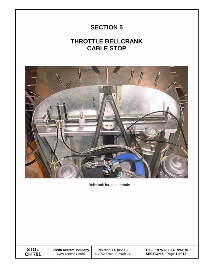
Bellcrank for dual throttle

STOL CH 701
Zenith Aircraft Company www.zenithair.com
912S FIREWALL FORWARDSECTION 5 - Page 2 of 12
Revision 1.0 (05/03) © 2002 Zenith Aircraft Co
Trim the bottom corner of the side flange on the vertical Top Channel 7F7-3 to make room for the Bellcrank 7E5-1
Set the Bellcarnk at 16mm from the Top Channel Stiffener 7F7-7SP to the center of the CHECK: The position of the Bellcrank 7E5-1 is behind the Stop Plate 7L1-5J
Layout the location of the 3/8” hole in the Friction Block 7E5-6 (referenced from the aft edge) 16mm to the center of the hole
FRICTION BLOCK 7E5-6 Qty=2 Nylon 66 Plastic 35mm x 25mm x ½” Note: 3mm between firewall and aft edge plastic block 7E5-6 TIP: The block is 35mm long, line up the front edge of the plastic block 7E5-6 even with the front edge of the extrusion Clamp 7E5-5

STOL CH 701
Zenith Aircraft Company www.zenithair.com
912S FIREWALL FORWARDSECTION 5 - Page 3 of 12
Revision 1.0 (05/03) © 2002 Zenith Aircraft Co
Clamp the two blocks in a drill vise, drill the 3/8” hole through both pieces.
3/8” drill bit
Note: The hole is not in the middle of the block to make room for the AN3 bolt
3/8” hole through both blocks
STOL CH 701
Zenith Aircraft Company www.zenithair.com
912S FIREWALL FORWARDSECTION 5 - Page 4 of 12
Revision 1.0 (05/03) © 2002 Zenith Aircraft Co
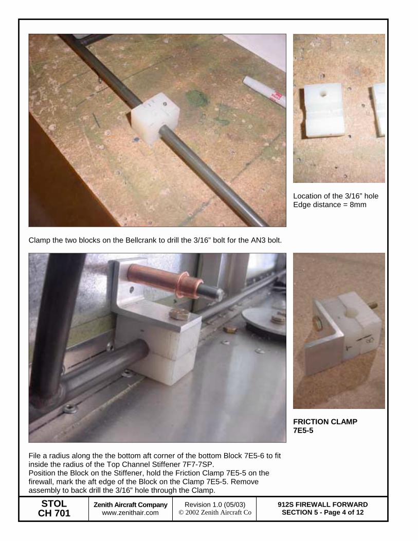
Clamp the two blocks on the Bellcrank to drill the 3/16” bolt for the AN3 bolt.
Location of the 3/16” hole Edge distance = 8mm
File a radius along the the bottom aft corner of the bottom Block 7E5-6 to fit inside the radius of the Top Channel Stiffener 7F7-7SP. Position the Block on the Stiffener, hold the Friction Clamp 7E5-5 on the firewall, mark the aft edge of the Block on the Clamp 7E5-5. Remove assembly to back drill the 3/16” hole through the Clamp.
FRICTION CLAMP 7E5-5

STOL CH 701
Zenith Aircraft Company www.zenithair.com
912S FIREWALL FORWARDSECTION 5 - Page 5 of 12
Revision 1.0 (05/03) © 2002 Zenith Aircraft Co
The Throttle friction clamp is installed 120 mm. to the right of the aircraft centerline. If necessary adjust the position of the friction clamp in between the existing rivets in the Stiffener – do not install the Clamp on top of a rivet. Back drill the 3/16” through the Block 7E5-6 into the Upper Channel 7F7-1SP
THROTTLE BELLCRANK 7E5-1 Welded assembly. ORIENTATION: Vertical rods are installed on the right side
NOTE: Add a washer (AN960-10) under the lower block, between block 7E5-6 and Channel 7F7-1SP
AN3-15A BOLT QTY: 1 (self locking nut and washer underneath Channel) 2 RIVETS A5 7E5-5 into firewall

STOL CH 701
Zenith Aircraft Company www.zenithair.com
912S FIREWALL FORWARDSECTION 5 - Page 6 of 12
Revision 1.0 (05/03) © 2002 Zenith Aircraft Co
With a file, radius the bottom edge to make room for the bend radius of the Top Channel Stiffener 7F7-7SP
THROTTLE BEARING 7E5-2 1L + 1R required. ORIENTATION: drill the 3/8” hole in the 1-1/2” flange, then chamfer the top edge. Drill the 3/8” hole 16mm from the aft edge and 12mm up from the bottom edge.
LOCATION: Line up the mid-point of the 600mm long Bellcrank 7E5-1 with the aircraft centerline. IMPORTANT: Do not install the Throttle Bearing 7E5-2 on top of a rivet.
Detail of left side 2 RIVETS A5 7E5-2 into firewall

STOL CH 701
Zenith Aircraft Company www.zenithair.com
912S FIREWALL FORWARDSECTION 5 - Page 7 of 12
Revision 1.0 (05/03) © 2002 Zenith Aircraft Co
Saw the side flange to the corner relief hole. Chamfer the 1” flange. With a square, mark bend line across the 1-1/2” flange 25mm from the top edge.
THROTTLE CABLE STOP (QTY=1) 7E5-3 Length = 120mm Drill a ¼” corner relief hole tangent with the 1-1/2” flange approximately 25mm from the top edge.
Note: If using a vise (as in photo above), only use aluminum grips with the appropriate radius. Bend approximately 45 degrees along the bend line.
IMPORTANT: Bend the extrusion over a piece of wood with a ¼” radius if a vice with aluminum grips (and radius) is NOT available. CHECK: That there are no visible crack along the bend. ORIENTATION: The bend is at the top with the 1” flange installed on the I/B side

STOL CH 701
Zenith Aircraft Company www.zenithair.com
912S FIREWALL FORWARDSECTION 5 - Page 8 of 12
Revision 1.0 (05/03) © 2002 Zenith Aircraft Co
Drill two ¼” holes 13mm part (center to center) on the bent 25mm end of the Throttle Cable Stop 7E5-3
SUGGESTION: Wait to Chamfer the bottom edges until after the diagonal L angle is drilled and Clecoed
Install the Cable Stop Adjuster assemblies 25-0700 to the Throttle Cable stop 7E5-3. Jam nuts on each side of 7E5-3.
25-0700 CABLE STOP ADJUSTER ASSEMBLY QTY: 4

STOL CH 701
Zenith Aircraft Company www.zenithair.com
912S FIREWALL FORWARDSECTION 5 - Page 9 of 12
Revision 1.0 (05/03) © 2002 Zenith Aircraft Co
Set the Bellcrank 6E5-1 in the full throttle position.
105mm = horizontal distance from the firewall to the top of the Bellrank
Clamp the Throttle Cable Stop 7E5-1 to the front flange of the Upper Channel 7E7-1SP; Drill & Cleco
VERTICAL HEIGHT: The ends of the Cable Stop Adjuster Assemblies should be in line with the center of the AN3-20 bolt on the Bellcrank. CHECK: That the sides of the Throttle Stop are vertical. 2 RIVETS A5 7E5-1 into 7F7-1SP

STOL CH 701
Zenith Aircraft Company www.zenithair.com
912S FIREWALL FORWARDSECTION 5 - Page 10 of 12
Revision 1.0 (05/03) © 2002 Zenith Aircraft Co
L angle = 100mm Installed in the corner of the Upper Channel 7F7-1SP and the Throttle Cable Stop 7E5-3. Chamfer (trim) the left and right corners.
2 RIVETS A5 7E5-3 into L angle
Top view (when standing in front of aircraft) 4 RIVETS A4 from L angle into 7F7-1SP

STOL CH 701
Zenith Aircraft Company www.zenithair.com
912S FIREWALL FORWARDSECTION 5 - Page 11 of 12
Revision 1.0 (05/03) © 2002 Zenith Aircraft Co
DIAGONAL L ANGLE 180mm measured along the firewall from the Upper channel to the bottom of the diagonal L angle
2 RIVETS A4 L angle into 7F7-5
Drill a #20 corner relief hole in the diagonal L angle and cut the top flange to make room 7F5-3. Cut the bottom side flange 7E5-3 flush with the bottom edge of the diagonal L angle. Chamfer the front of 7E5-3 even with the bottom of the upper channel
2 RIVETS A4 7E5-3 into L angle

STOL CH 701
Zenith Aircraft Company www.zenithair.com
912S FIREWALL FORWARDSECTION 5 - Page 12 of 12
Revision 1.0 (05/03) © 2002 Zenith Aircraft Co
Drill the two 1/16” hole in the AN3 bolt for the throttle cables (parallel holes).
AN3-20 Bolt on bellcrank 7E5-1
CHECK: The holes in the AN3 bolt are in line with the center of the cable stop adjuster assemblies 25-0700