segmentation and modelling of visually symmetricobjects by robot actions
TRANSCRIPT
8/3/2019 Segmentation and Modelling of Visually SymmetricObjects by Robot Actions
http://slidepdf.com/reader/full/segmentation-and-modelling-of-visually-symmetricobjects-by-robot-actions 1/19
1
Segmentation and Modelling of Visually Symmetric
Objects by Robot ActionsWai Ho Li and Lindsay Kleeman
Intelligent Robotics Research Centre
Department of Electrical and Computer Systems Engineering
Monash University, Clayton, Victoria 3800, Australia
{ Wai.Ho.Li, Lindsay.Kleeman } @eng.monash.edu.au
Abstract—Robots usually carry out object segmentation andmodelling passively. Sensors such as cameras are actuated by arobot without disturbing objects in the scene. In this paper, wepresent an intelligent robotic system that physically moves objectsin an active manner to perform segmentation and modelling usingvision. By visually detecting bilateral symmetry, our robot isable to segment and model objects through controlled physical
interactions. Extensive experiments show that our robot is able toaccurately segment new objects autonomously. We also show thatour robot is able leverage segmentation results to autonomouslylearn visual models of new objects by physically grasping androtating them. Object recognition experiments confirm that therobot-learned models allow robust recognition. Videos of roboticexperiments are available from Multimedia Extensions 1, 2 and3.
Index Terms—fast symmetry, real time, computer vision,autonomous, segmentation, robotics, object recognition, SIFT,interactive learning, object manipulation, grasping
I. INTRODUCTION
The ability to perform object segmentation and modelling
used to be the exclusive domain of higher primates. With
passing time, computer vision research has produced ever im-
proving systems that can segment and model objects. Modern
techniques such as Interactive Graph Cuts [Boykov and Jolly,
2001] and Geodesic Active Contours [Markus et al., 2008] can
produce accurate segmentations given some human guidance.
Similarly, visual features such as SIFT [Lowe, 2004], Gabor
Filter banks [Mutch and Lowe, 2006] and Haar wavelets [Viola
and Jones, 2001] enable reliable object detection and recogni-
tion, especially when combined with machine learning meth-
ods such as Boosting using AdaBoost [Freund and Schapire,
1997]. However, these computer vision techniques rely heavily
on a priori knowledge of objects and their surroundings, such
as initial guesses of foreground-background pixels, which is
difficult to obtain autonomously in real world situations.
This paper presents a robotic system that applies physical
actions to segment and model new objects using vision. The
system is composed of a robot arm that moves objects within
its workspace inside the field of view of a stereo camera
pair. The arm-camera geometry is configured to mimic a
humanoid platform operating on objects supported by a flat
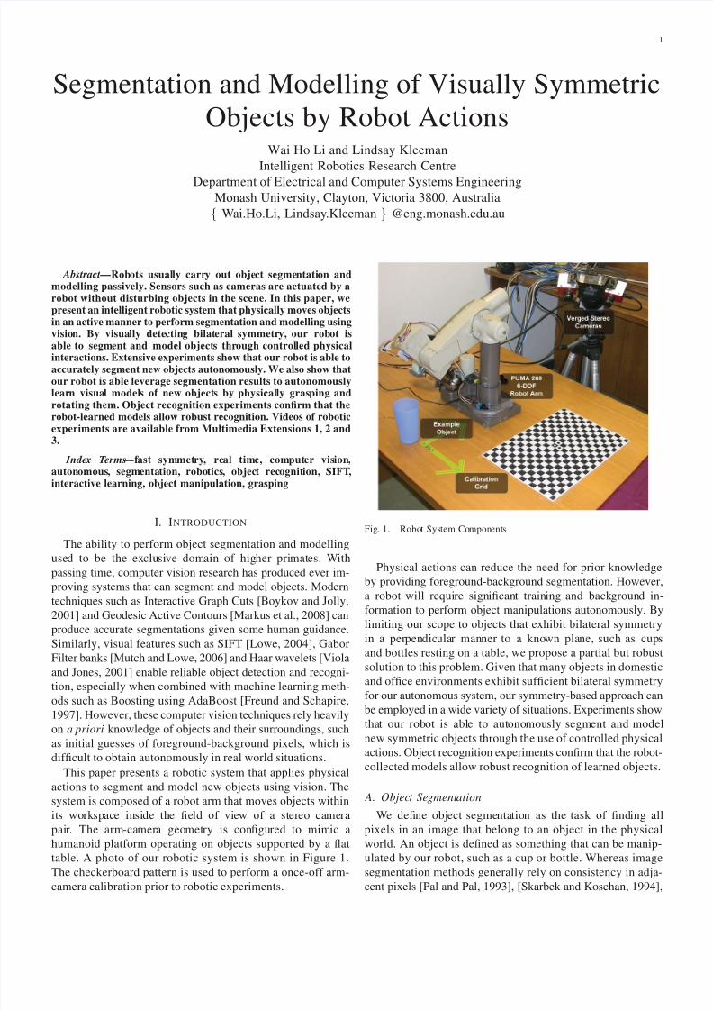
table. A photo of our robotic system is shown in Figure 1.
The checkerboard pattern is used to perform a once-off arm-
camera calibration prior to robotic experiments.
Fig. 1. Robot System Components
Physical actions can reduce the need for prior knowledge
by providing foreground-background segmentation. However,
a robot will require significant training and background in-
formation to perform object manipulations autonomously. By
limiting our scope to objects that exhibit bilateral symmetry
in a perpendicular manner to a known plane, such as cups
and bottles resting on a table, we propose a partial but robust
solution to this problem. Given that many objects in domestic
and office environments exhibit sufficient bilateral symmetry
for our autonomous system, our symmetry-based approach can
be employed in a wide variety of situations. Experiments showthat our robot is able to autonomously segment and model
new symmetric objects through the use of controlled physical
actions. Object recognition experiments confirm that the robot-
collected models allow robust recognition of learned objects.
A. Object Segmentation
We define object segmentation as the task of finding all
pixels in an image that belong to an object in the physical
world. An object is defined as something that can be manip-
ulated by our robot, such as a cup or bottle. Whereas image
segmentation methods generally rely on consistency in adja-
cent pixels [Pal and Pal, 1993], [Skarbek and Koschan, 1994],

8/3/2019 Segmentation and Modelling of Visually SymmetricObjects by Robot Actions
http://slidepdf.com/reader/full/segmentation-and-modelling-of-visually-symmetricobjects-by-robot-actions 2/19
2
object segmentation requires external knowledge so that the re-
sulting segments are physically meaningful. For example, prior
knowledge of background pixel statistics is used to perform
object segmentation via background subtraction [Elgammal
et al., 2000]. Similarly, interactive segmentation approaches
rely on a priori information provided by a human user to
produce useful segmentations. Such prior information allows
object segmentation despite variations in pixel value within anobject and similarities in pixel value between an object and
the background.
Our robotic system uses physical interaction to provide prior
information for object segmentation. Not to be confused with
human-robot interaction or human-computer interaction, our
robot physically interacts with objects in order to perform
segmentation. Instead of actuating a camera in an eye-in-hand
configuration, our robot actuates the object while keeping
its cameras fixed. By having a robotic agent interactively
move objects in a scene, our approach breaks the traditional
computer vision paradigm of passive observation.
The notion of using robotic action to aid object segmen-
tation was first proposed in [Tsikos and Bajcsy, 1988]. More
recently, [Fitzpatrick, 2003], [Fitzpatrick and Metta, 2003] and
[Kenney et al., 2009] showed that object segmentation can be
performed using a robotic agent that employs a blind poking
action to move objects. By limiting our scope to objects with
visual symmetry, our approach improves on these recent works
by decoupling object detection and object segmentation.
Recent interactive object segmentation approaches essen-
tially sweeps the end effector across a scene to try and
poke objects. Object detection and segmentation are performed
simultaneously when the robot detects a jump in visual motion
beyond that of its moving end effector. In essence, the chance
collision of the end effector with a new object provides a newsegmentation. It is important to note that the robot does not
hold any expectations as to if and when the effector-object
collision occurs as the robot is blind to the objects in the
scene.
In contrast, our robot detects a new symmetric object and
then moves the object using a planned manipulation. This
plan-then-act approach allows segmentation to be delayed
until after object motion has ceased. This differs from recent
approaches that performs detection and segmentation at the
time of effector-object contact, which can produce poor seg-
ments as the initial object motion can occur between video
frames. Such poor segmentations are highlighted in Figure 11
of [Fitzpatrick and Metta, 2003], which shows that the robot’s
end effector can be included in the segmentation results. Near-
empty segmentations were also returned by their approach.
Similarly, Figures 6 and 9 of [Kenney et al., 2009] show small
chunks missing from the object segmentations.
By incorporating real time object tracking into our segmen-
tation approach, we are able to perform motion segmentation
using video frames taken before and after object motion. This
prevents poor segmentations due to insufficient or unexpected
object motion. In addition, object symmetry is used to im-
prove object segmentations. Object segmentations produced
autonomously by our robot, including results for transparent
objects, are shown in Section VIII-A.
Fitzpatrick et al and Kenney et al applies a relatively
high-speed poke to actuate objects for motion segmentation.
This is because segmentation is performed using motion or
motion templates that arise during effector-object contact.
As such, the end effector must move quickly to generate
enough motion during object contact to initiate segmentation.
In contrast, our plan-then-act approach allows the use of a
gentle and purposeful robotic nudge to actuate objects sincesegmentation is performed using the video frames before and
after object motion. The limiting factor for the robotic nudge
is merely overcoming static friction between an object and the
supporting surface. In experiments, we show that our method
does not tip over tall objects such as empty bottles and does
not damage fragile objects such as ceramic mugs. Fitzpatrick
and Kenney did not test their segmentation approaches on any
fragile or top-heavy objects.
B. Object Modelling
Robust object recognition requires large quantities of train-
ing data, such as hand-labelled images of a target object underdifferent illumination conditions. The fact that each new object
in the recognition database requires new training data further
compounds the problem in real world environments. While
one-shot learning [Fei-Fei et al., 2006] provides some hope
for the future, robust object recognition still depends heavily
on large quantities of training data. Our robot is able to break
this traditional dependence on hand-labelled data by collecting
its own training images when it encounters a new object.
The object modelling process begins with the robot moving
a new object over a short distance using a robotic nudge.
However, moving an object on a table only provides a single
view of the moved object. The object’s height is estimatedusing the left and right camera segmentations by assuming a
convex hull with a flat upper surface. This allows our robot
to physically pick up the nudged object. The robot’s ability
to move autonomously from a simple nudge to the more
advanced grasp is novel and useful in situations where the
robot has to deal with new objects.
After segmentation, the robot picks up the nudged object
and rotates it to collect training images over the entire 360
degrees of the grasped object. Object models are constructed
using these robot-collected training images. The proposed
approach differs from the traditional approach of offline image
collection and feature detection using a turntable-camera rig
as surveyed in [Moreels and Perona, 2005]. Our approach
also differs from semi-autonomous systems, such as [Kim
et al., 2006], that require a human user to provide the robot
with different views of a test object. Instead, our robot
autonomously learns new objects by modelling them online.
Object recognition experiments suggests that the robot is able
to learn useful visual models of textured objects.
The robot’s gripper has two wide foam fingers, which can
be seen in Figure 2. The foam-padded gripper ensures a
stable grasp but does not allow an accurate pose estimate of
the grasped object. This means that foreground-background
segmentation is not available during training image collection.
As such, multi-view object recognition methods such as [Chen
8/3/2019 Segmentation and Modelling of Visually SymmetricObjects by Robot Actions
http://slidepdf.com/reader/full/segmentation-and-modelling-of-visually-symmetricobjects-by-robot-actions 3/19
3
and Chen, 2004] are unsuitable because they rely on well seg-
mented training images. Instead, our approach extracts SIFT
descriptors [Lowe, 2004] from the robot-collected training
images to model objects. As the inclusion of background SIFT
descriptors in the object model can produce false positives
during recognition, we have developed an automatic descriptor
pruning method. The pruning method compares descriptors be-
tween the images within a robot-collected training set to rejectbackground descriptors. The pruning method is applicable to
any SIFT detection scenario where an object is rotated in front
of a static background.
II. SYSTEM OVERVIEW
A. Robot Hardware
The components of our robot are shown in Figure 1. Two
Videre Design IEEE1394 colour CMOS cameras form a stereo
pair. The cameras are verged together at an angle of 15 degrees
from parallel to provide a greater overlap in the stereo view
of the table. A PUMA260 six degree-of-freedom robot arm is
used to perform simple object manipulations. The calibrationgrid is used to obtain the geometric relationship between the
stereo cameras and the robot arm, as well as to determine
the geometry of the table plane. Details of the arm-camera
calibration are provided in Section II-B.
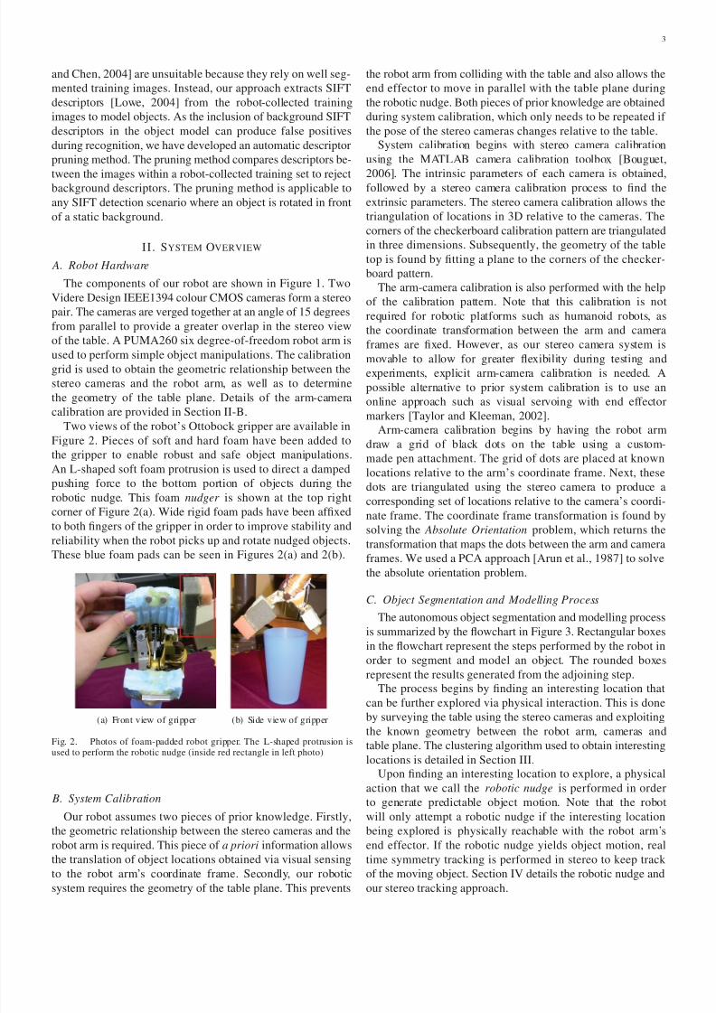
Two views of the robot’s Ottobock gripper are available in
Figure 2. Pieces of soft and hard foam have been added to
the gripper to enable robust and safe object manipulations.
An L-shaped soft foam protrusion is used to direct a damped
pushing force to the bottom portion of objects during the
robotic nudge. This foam nudger is shown at the top right
corner of Figure 2(a). Wide rigid foam pads have been affixed
to both fingers of the gripper in order to improve stability and
reliability when the robot picks up and rotate nudged objects.
These blue foam pads can be seen in Figures 2(a) and 2(b).
(a) Front view of gripper (b) Side view of gripper
Fig. 2. Photos of foam-padded robot gripper. The L-shaped protrusion isused to perform the robotic nudge (inside red rectangle in left photo)
B. System Calibration
Our robot assumes two pieces of prior knowledge. Firstly,
the geometric relationship between the stereo cameras and the
robot arm is required. This piece of a priori information allows
the translation of object locations obtained via visual sensing
to the robot arm’s coordinate frame. Secondly, our robotic
system requires the geometry of the table plane. This prevents
the robot arm from colliding with the table and also allows the
end effector to move in parallel with the table plane during
the robotic nudge. Both pieces of prior knowledge are obtained
during system calibration, which only needs to be repeated if
the pose of the stereo cameras changes relative to the table.
System calibration begins with stereo camera calibration
using the MATLAB camera calibration toolbox [Bouguet,
2006]. The intrinsic parameters of each camera is obtained,followed by a stereo camera calibration process to find the
extrinsic parameters. The stereo camera calibration allows the
triangulation of locations in 3D relative to the cameras. The
corners of the checkerboard calibration pattern are triangulated
in three dimensions. Subsequently, the geometry of the table
top is found by fitting a plane to the corners of the checker-
board pattern.
The arm-camera calibration is also performed with the help
of the calibration pattern. Note that this calibration is not
required for robotic platforms such as humanoid robots, as
the coordinate transformation between the arm and camera
frames are fixed. However, as our stereo camera system is
movable to allow for greater flexibility during testing andexperiments, explicit arm-camera calibration is needed. A
possible alternative to prior system calibration is to use an
online approach such as visual servoing with end effector
markers [Taylor and Kleeman, 2002].
Arm-camera calibration begins by having the robot arm
draw a grid of black dots on the table using a custom-
made pen attachment. The grid of dots are placed at known
locations relative to the arm’s coordinate frame. Next, these
dots are triangulated using the stereo camera to produce a
corresponding set of locations relative to the camera’s coordi-
nate frame. The coordinate frame transformation is found by
solving the Absolute Orientation problem, which returns thetransformation that maps the dots between the arm and camera
frames. We used a PCA approach [Arun et al., 1987] to solve
the absolute orientation problem.
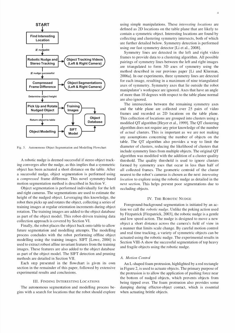
C. Object Segmentation and Modelling Process
The autonomous object segmentation and modelling process
is summarized by the flowchart in Figure 3. Rectangular boxes
in the flowchart represent the steps performed by the robot in
order to segment and model an object. The rounded boxes
represent the results generated from the adjoining step.
The process begins by finding an interesting location that
can be further explored via physical interaction. This is done
by surveying the table using the stereo cameras and exploiting
the known geometry between the robot arm, cameras and
table plane. The clustering algorithm used to obtain interesting
locations is detailed in Section III.
Upon finding an interesting location to explore, a physical
action that we call the robotic nudge is performed in order
to generate predictable object motion. Note that the robot
will only attempt a robotic nudge if the interesting location
being explored is physically reachable with the robot arm’s
end effector. If the robotic nudge yields object motion, real
time symmetry tracking is performed in stereo to keep track
of the moving object. Section IV details the robotic nudge and
our stereo tracking approach.
8/3/2019 Segmentation and Modelling of Visually SymmetricObjects by Robot Actions
http://slidepdf.com/reader/full/segmentation-and-modelling-of-visually-symmetricobjects-by-robot-actions 4/19
4
Find Interesting
Location
Robotic Nudge andStereo Tracking
Compressed
Frame Difference
START
Object Segmentations
(Left & Right Camera)
Pick Up and Rotate
Nudged Object
Object ModellingSIFT
Model
IF nudgable
IF nudge successful
Determine object height
Training
Images
Object Tracking Videos(Left & Right Camera)
ObjectDatabase
Return object to table
Fig. 3. Autonomous Object Segmentation and Modelling Flowchart
A robotic nudge is deemed successful if stereo object track-
ing converges after the nudge, as this implies that a symmetric
object has been actuated a short distance on the table. After
a successful nudge, object segmentation is performed usinga compressed frame difference. This novel symmetry-based
motion segmentation method is described in Section V.
Object segmentation is performed individually for the left
and right cameras. The segmentations are used to estimate the
height of the nudged object. Leveraging this knowledge, the
robot then picks up and rotates the object, collecting a series of
training images at regular orientation increments during object
rotation. The training images are added to the object database
as part of the object model. This robot-driven training data
collection approach is covered by Section VI.
Finally, the robot places the object back onto table to allow
future segmentation and modelling attempts. The modelling
process concludes with the robot performing offline object
modelling using the training images. SIFT [Lowe, 2004] is
used to extract robust affine invariant features from the training
images. These features are also added to the object database
as part of the object model. The SIFT detection and pruning
methods are detailed in Section VII.
Each step presented in the flowchart is given its own
section in the remainder of this paper, followed by extensive
experimental results and conclusions.
III. FINDING INTERESTING LOCATIONS
The autonomous segmentation and modelling process be-
gins with a search for locations that the robot should explore
using simple manipulations. These interesting locations are
defined as 2D locations on the table plane that are likely to
contain a symmetric object. Interesting locations are found by
collecting and clustering symmetry intersects, both of which
are further detailed below. Symmetry detection is performed
using our fast symmetry detector [Li et al., 2008].
Symmetry lines are detected in the left and right video
frames to provide data to a clustering algorithm. All possiblepairings of symmetry lines between the left and right images
are triangulated to form 3D axes of symmetry using the
method described in our previous paper [Li and Kleeman,
2006a]. In our experiments, three symmetry lines are detected
for each image, resulting in a maximum of nine triangulated
axes of symmetry. Symmetry axes that lie outside the robot
manipulator’s workspace are ignored. Axes that have an angle
of more than 10 degrees with respect to the table plane normal
are also ignored.
The intersections between the remaining symmetry axes
and the table plane are collected over 25 pairs of video
frames and recorded as 2D locations on the table plane.
This collection of locations are grouped into clusters using a
modified QT algorithm [Heyer et al., 1999]. The QT clustering
algorithm does not require any prior knowledge of the number
of actual clusters. This is important as we are not making
any assumptions concerning the number of objects on the
table. The QT algorithm also provides a way to limit the
diameter of clusters, reducing the likelihood of clusters that
include symmetry lines from multiple objects. The original QT
algorithm was modified with the addition of a cluster quality
threshold. The quality threshold is used to ignore clusters
formed by symmetry axes that occur in less than half of
all collected frames. The geometric centroid of the cluster
nearest to the robot’s cameras is chosen as the next interestinglocation to explore using the robotic nudge as detailed in the
next section. This helps prevent poor segmentations due to
occluding objects.
IV. THE ROBOTIC NUDGE
Foreground-background segmentation is initiated by an ac-
tion we call the robotic nudge. Unlike the poking action used
by Fitzpatrick [Fitzpatrick, 2003], the robotic nudge is a gentle
and low speed action. The nudge is designed to move a new
object a short distance across the camera’s field of view in
a manner that limits scale change. By careful motion control
and real time tracking, a variety of symmetric objects can beactuated using the robotic nudge. The experimental results in
Section VIII-A show the successful segmentation of top heavy
and fragile objects using the robotic nudge.
A. Motion Control
An L-shaped foam protrusion, highlighted by a red rectangle
in Figure 2, is used to actuate objects. The primary purpose of
the protrusion is to allow the application of pushing force near
the bottom of nudged objects, which prevents objects from
being tipped over. The foam protrusion also provides some
damping during effector-object contact, which is essential
when actuating brittle objects.

8/3/2019 Segmentation and Modelling of Visually SymmetricObjects by Robot Actions
http://slidepdf.com/reader/full/segmentation-and-modelling-of-visually-symmetricobjects-by-robot-actions 5/19
5
Figure 4 shows the side view of the robotic nudge motion.
The nudge is performed by moving the end effector in an L-
shaped trajectory. The height of P 0 is well above the height
of the tallest expected object. Dmax is set to allow enough
clearance so that the L-shaped foam protrusion does not collide
with objects as it is lowered. In our robotic experiments, Dmax
was set to provide a safety margin of 20mm. Dmin is chosen
so that the smallest expected object will be sufficiently actu-ated by the robotic nudge for subsequent motion segmentation.
Note that the L-shaped nudge motion is essential. In early
experiments, the gripper retreated from P 2 directly to P 0,
which knocked over objects that are wider on top such as the
plastic cup in Figure 14.
Fig. 4. The robotic nudge: Side view
An overhead view of the robotic nudge is provided in
Figure 5. Note that the nudge is performed along a vector
that is perpendicular to the line formed between the right
camera’s focal point and the target object’s symmetry axis.
This reduces the scale change incurred by the object as it is
actuated across the camera’s field of view and also lowers the
probability of object rotation due to indirect contact. As such,
the robotic nudge is designed to improve the quality of motion
segmentation.
Fig. 5. The robotic nudge: Overhead view
After finding a location of interest, the robot calculates
the positions P 0, P 1 and P 2 based on the right camera’s
location. Linearly interpolated encoder values are generated
using inverse kinematics at run time to move the end effector
smoothly between these three points. A robotic nudge captured
by the right camera can be seen in Figure 6.
Fig. 6. Right camera video frames captured during a nudge. The frames aretaken from the P 1-P 2-P 1 part of the robotic nudge
B. Stereo Tracking using Symmetry
During the robotic nudge, the right camera image is moni-
tored for object motion. Motion detection is performed on the
part of the image coloured green in Figure 4. By ignoring
motion between the object’s symmetry line and the end
effector, the robot’s ego motion will not be misinterpreted
as object motion. Motion detection is performed using the
block motion algorithm in our fast symmetry tracker [Li andKleeman, 2006b].
After detecting object motion, tracking is performed on
the object’s symmetry line using a Kalman filter. Tracking
is performed independently on both cameras in the stereo
pair and continues until the nudged object stops moving.
Motion segmentation will only take place if both trackers
converge to symmetry lines that triangulate to a symmetry axis
roughly perpendicular to the table plane. This prevents poor
segmentation caused by insufficient object motion. Note that
if no object motion is detected, tracking is not performed and
the object learning process begins anew at the next location
of interest.
V. OBJECT SEGMENTATION BY COMPRESSED FRAME
DIFFERENCE
Our fast symmetry detector was previously used to perform
static object segmentation [Li et al., 2008]. This dynamic
programming approach generates object contours by linking
edges using a symmetry constraint. It is unable to recover
asymmetric parts of symmetric objects such as cup handles.
It is also prone to edge noise and background symmetry,
which may result in segmentations that are inaccurate when
compared against the actual physical object. This section
presents a new motion segmentation approach that remedies
these problems by making use of the quasi-predictable object
motion generated by the robotic nudge.
The motion segmentation process is illustrated by Figure 7.
The right camera image before and after the robotic nudge
are shown in Figures 7(a) and 7(b). Motion segmentation
begins by computing the absolute frame difference between
the before and after images, which results in the image in
Figure 7(c). The object’s symmetry lines before and after the
robotic nudge are overlaid onto the frame difference image as
green lines. Note that thresholding the frame difference image
at this stage will produce a segmentation mask that includes
too many background pixels. Also, if the moving object is not
highly textured, a large gap will be present at the centre of the
8/3/2019 Segmentation and Modelling of Visually SymmetricObjects by Robot Actions
http://slidepdf.com/reader/full/segmentation-and-modelling-of-visually-symmetricobjects-by-robot-actions 6/19
6
motion mask. Both problems can be seen in Figure 7(c). We
can overcome these problems by using the object’s symmetry
to our advantage.
(a) Before Nudge (b) After Nudge (c) Frame Difference
(d) Compressed Differ-ence (e) Symmetry Filled (f) Segmentation Result
Fig. 7. Segmentation by Compressed Frame Difference. The CompressedDifference and Symmetry Filled images are rotated so that the object’ssymmetry line is vertical
The compressed frame difference is shown in Figure 7(d).
This image is generated by removing the pixels between the
symmetry lines in the frame difference image, compressing
the two symmetry lines into one. This process also removes
changes in the object’s orientation caused by the robotic
nudge. Notice that the compressed frame difference no longer
includes many background pixels. The motion gap present
in the raw frame difference image is also smaller in thecompressed frame difference.
A small motion gap may remain in the compressed frame
difference. This can be seen in Figure 7(d) as a dark V-
shape bisected by the symmetry line. To remedy this, we
again exploit object symmetry to our advantage. The result
in Figure 7(e) is obtained by following the symmetry filling
process illustrated in Figure 8.
Fig. 8. Symmetry filling process used to generated the result in Figure 7(e)
Recall that the compression step merges the symmetry lines
of the object in the before and after frames. Using this newly
merged symmetry line as a mirror, we search for motion on
either side of it. A pixel is considered moving if its frame
difference value is above a threshold. These pixels are coloured
gray in Figure 8. The filling process marks all pixels from
the symmetry line to the outer most symmetric pixel pair as
moving. This allows the process to fill motion gaps in the
interior of an object while retaining asymmetric parts of a
symmetric object such as the handle of a mug. The object
segmentation result in Figure 7(f) is obtained by using the
symmetry filled image as a mask.
V I. PICKING UP AND ROTATING NUDGED OBJECTS
The object modelling process begins after the robotic nudge.The robot uses the object segmentation results from both
cameras to estimate the height of the object. The top of the
nudged object in the image is determined by following the
object’s symmetry line upwards. The top of the object is
where its symmetry line intersects with the object-background
boundary of its segmentation. Figure 9 visualizes an object’s
symmetry line and the top of the object as detected by our
robotic system.
(a) Left camera image (b) Right camera image
Fig. 9. The top of a nudged object’s symmetry line as detected by the robot
Figure 10 illustrates how an object’s height is estimated
using its symmetry axis. The symmetry axis is produced by
the same stereo triangulation process employed in Section III.
The blue line joins the camera’s focal point and the top of the
object as detected in the camera view. The estimated heightis marked as a black dot. Note that the estimated height has a
systematic bias that makes it greater than the actual height
of the physical object. Height estimates from the left and
right camera views are cross-checked for consistency before
attempting to grasp the object.
Fig. 10. Object height estimation using symmetry axis showing systematicbias in height estimate.
In Figure 10, r represents the object radius and d is the
systematic bias of the estimated height. In cases where the
object deviates from a surface of revolution, r represents the
horizontal distance between the object’s symmetry axis and
the point on the top of the object that is furthest from the

8/3/2019 Segmentation and Modelling of Visually SymmetricObjects by Robot Actions
http://slidepdf.com/reader/full/segmentation-and-modelling-of-visually-symmetricobjects-by-robot-actions 7/19
7
camera. The angle between the camera’s viewing direction
and the table plane is labelled as θ. Using similar triangles,
the height error d is described by the following equation. Note
that the equation assumes an object with a convex hull that
has a flat upper surface and ignores the effects of an object
appearing off centre in the camera image.
d = r tanθ (1)
For our experimental rig, which simulates the arm-camera
geometry of a humanoid platform, θ is roughly 30 degrees. As
we are only interested in robot-graspable objects, we assume
radii ranging from 30mm to 90mm. This produces a d error
value between 18mm and 54mm. To compensate for this error,
the gripper is vertically offset downwards by 36mm during
object grasping. As the vertical tolerance of the robot’s two-
fingered end effector is well over ±18mm, object grasping
is reliable as demonstrated by the experiments detailed in
Sections VIII-B and IX.
A. Training Image Collection
After estimating the nudged object’s height, grasping is
performed by lowering the opened gripper vertically along the
object’s symmetry axis. When the gripper arrives at the top of
the object, offset downwards by the height triangulation error
d, a power grasp is performed by closing the gripper. The
object is raised until most of the gripper is outside the field of
view of the stereo cameras. This helps prevent the inclusion
of end effector features in the object’s model.
Training images are collected by rotating the grasped object
about a vertical axis. Right camera images are taken at 30-
degree intervals over 360 degrees to produce 12 trainingimages per object. The 30-degree angle increment is chosen
according to the ±15 degrees view point tolerance reported
for SIFT descriptors [Lowe, 2004]. The first two images of a
training set collected by the robot is shown in Figure 11. Each
training image is 640× 480 pixels in size.
Fig. 11. Two of twelve images in the green bottle training set. The right imagewas captured after the robot has rotated the grasped object by 30 degrees
VII. OFFLINE OBJECT MODELLING USING SIFT
The scale invariant feature transform (SIFT) [Lowe, 2004]
is a multi-scale feature detection method that extracts unique
descriptors from affine regions in an image. It is attractive
for robotic applications because SIFT descriptors are robust
against translation, rotation, illumination changes and small
changes in viewing angle.
A. SIFT Detection
Recall that the robot rotates a grasped object to collect
12 training images at 30-degree increments. After object
manipulation, SIFT detection is performed on each image in
a training set using David Lowe’s binary implementation. Our
own C/C++ code is used to match and visualize descriptors.
The locations of SIFT descriptors detected in a training image
are shown as blue dots in Figure 12(a). Note the densecoverage of descriptors over the grasped object.
B. Pruning Background Descriptors
Figure 12(a) highlights the need to prune non-object de-
scriptors before building object models. The inclusion of
non-object descriptors may lead to false positives in future
object recognition attempts. This problem will be especially
prominent when the robot is operating on objects set against
similar backgrounds.
An automatic pruning method is used to remove non-object
descriptors as well as repetitive object descriptors. The pruned
result is shown in Figure 12(b). Notice that the majorityof background descriptors, including the descriptor extracted
from the object’s shadow, have been successfully removed. Ex-
periments suggests that the remaining non-object descriptors
have negligible effect on object recognition performance.
(a) All detected descriptors
(b) Background descriptors pruned
Fig. 12. Pruning background SIFT descriptors
Pruning is performed as follows. Firstly, a loose bounding
box is placed around the grasped object to remove background
descriptors. The bounding box is large enough to accom-
modate the object tilt and displacement that occurs during
8/3/2019 Segmentation and Modelling of Visually SymmetricObjects by Robot Actions
http://slidepdf.com/reader/full/segmentation-and-modelling-of-visually-symmetricobjects-by-robot-actions 8/19
8
rotation. This step removes a large portion of background
descriptors.
The second pruning step searches within an entire training
set to remove background descriptors. As the grasped object is
rotated in front of a static background, background descriptors
will occur much more frequently within a training image set.
We assume that an object descriptor in the current training
image may also be detected in the images collected at theprevious object rotation as well as the next object rotation. This
means a descriptor belonging to the grasped object should only
match with a maximum of two descriptors from other images
in the same training set. The second pruning step makes use
of this observation by removing descriptors that have three or
more matches with descriptors from other images in the same
training set.
Our automatic pruning method should generalize to any
SIFT feature set collected from images of an object rotated in
front of a static background. The descriptor threshold in the
second pruning step can be adjusted based on the object rota-
tion increment between training images. Apart from increasing
object recognition robustness by reducing the probability of
false positives, the reduction in the number of descriptors also
reduces the computational cost of recognition. In the example
shown in Figure 12, the number of descriptors is reduced from
268 to 163.
C. Object Recognition
The robot’s object recognition system is described in Fig-
ure 13. An object database is created from autonomously
collected training images. Each object is modelled in the
database by twelve images, the SIFT descriptors detected in
these images and an object label. Note that SIFT detectionis performed on grayscale images so no colour information
is retained in the database. The object label is a text string
specified by the user.
0o 30o 60o 330o
OBJECT LABEL: White Bottle
SIFT Descriptor Sets fr om 12 Training Images
OBJECT LABEL: Yellow Bottle
OBJECT LABEL: Transparent Bottle
OBJECT DATABASE
Input Image
DetectSIFT
Compute Matches withall Descriptor Sets
0o 30o 60o 330o
SIFT Descriptor Sets fr om 12 Training Images
0o 30o 60o 330o
SIFT Descriptor Sets fr om 12 Training Images
Object RecognitionResults
Object Label ofBest SIFT Set
Best SIFTDescriptor Set
Training Imageof Best SIFT Set
Set with MostMatches is BEST
InputSIFT
Descriptors
Fig. 13. Object recognition using SIFT
Object recognition is done by comparing an input image
against the object database. SIFT detection is performed on
the input image to obtain a set of input descriptors. The
input descriptors are matched against all descriptor sets in
the database, which are drawn as green squares with angles
in Figure 13. Two descriptors are considered to match if the
Euclidean distance between them is smaller than 0.6 times
the distance between the second best match. The descriptor
set with the most matches is considered the best . The ob-
ject recognition system also returns the training image and
object label associated with the best descriptor set. As pose
estimation requires three correct matches [Lowe, 2004], therecognition system will only return a result when three or
more matches are found.
VIII. ROBOTIC EXPERIMENTS
Three sets of experiments were carried out using our robotic
system. Firstly, experimental results where the robot only ap-
plies the nudge action in order to segment objects is presented.
Limited results were presented in [Li and Kleeman, 2008].
Secondly, the results of the robot using both the nudge and
grasp actions to model objects are presented. Some preliminary
results were previously presented in [Li and Kleeman, 2009].
These experiments are presented as individual subsectionswithin the current section.
Thirdly, we present an extensive set of experiments that tests
the limits of our autonomous system to examine its robustness
and identify failure modes. Due to the length of the results,
these new experiments are presented separately in the next
section.
Results from the three sets of experiments are highlighted
in Multimedia Extensions 1, 2 and 3 respectively.
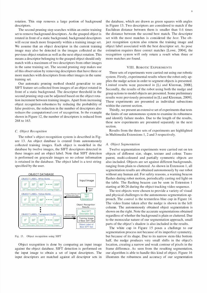
A. Object Segmentation
Twelve segmentation experiments were carried out on ten
objects of different size, shape, texture and colour. Trans-parent, multi-coloured and partially symmetric objects are
also included. Objects are set against different backgrounds,
ranging from plain to cluttered. As shown in Extension 1, all
segmentation results are obtained autonomously by our robot
without any human aid. For safety reasons, a warning beacon
flashes during robot motion, periodically casting red light on
the table. The flashing beacon can be seen in Extension 1
starting at 00:26 during the object tracking video sequence.
The test objects were chosen to provide a variety of visual
and physical challenges to the autonomous segmentation ap-
proach. The control is the textureless blue cup in Figure 14.
The video frame taken after the nudge is shown in the left
column. The autonomously obtained object segmentation is
shown on the right. Note the accurate segmentations obtained
regardless of whether the background is plain or cluttered. Due
to the monocular nature of our segmentation approach, small
parts of the object’s shadow is also included in the results.
The white cup in Figure 15 poses a challenge to our
segmentation process not because of its imperfect symmetry,
but because of its shape. Due to its narrow stem-like bottom
half, the nudge produces very small shifts in the object’s
location, creating a narrow and weak contour of pixels in the
frame difference. As seen from the resulting segmentation,
our algorithm is able to handle this kind of object. Figure 16
illustrates the robustness and accuracy of our segmentation
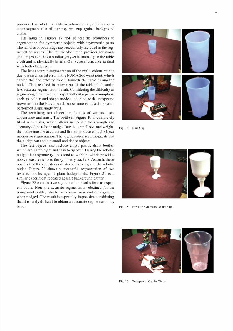
8/3/2019 Segmentation and Modelling of Visually SymmetricObjects by Robot Actions
http://slidepdf.com/reader/full/segmentation-and-modelling-of-visually-symmetricobjects-by-robot-actions 9/19
9
process. The robot was able to autonomously obtain a very
clean segmentation of a transparent cup against background
clutter.
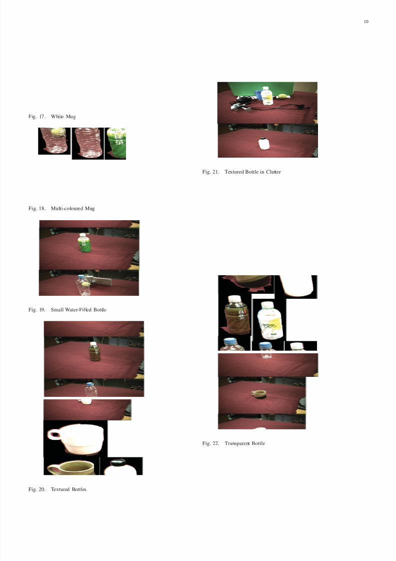
The mugs in Figures 17 and 18 test the robustness of
segmentation for symmetric objects with asymmetric parts.
The handles of both mugs are successfully included in the seg-
mentation results. The multi-colour mug provides additional
challenges as it has a similar grayscale intensity to the tablecloth and is physically brittle. Our system was able to deal
with both challenges.
The less accurate segmentation of the multi-colour mug is
due to a mechanical error in the PUMA 260 wrist joint, which
caused the end effector to dip towards the table during the
nudge. This resulted in movement of the table cloth and a
less accurate segmentation result. Considering the difficulty of
segmenting a multi-colour object without a priori assumptions
such as colour and shape models, coupled with unexpected
movement in the background, our symmetry-based approach
performed surprisingly well.
The remaining test objects are bottles of various sizes,
appearance and mass. The bottle in Figure 19 is completely
filled with water, which allows us to test the strength and
accuracy of the robotic nudge. Due to its small size and weight,
the nudge must be accurate and firm to produce enough object
motion for segmentation. The segmentation result suggests that
the nudge can actuate small and dense objects.
The test objects also include empty plastic drink bottles,
which are lightweight and easy to tip over. During the robotic
nudge, their symmetry lines tend to wobble, which provides
noisy measurements to the symmetry trackers. As such, these
objects test the robustness of stereo tracking and the robotic
nudge. Figure 20 shows a successful segmentation of two
textured bottles against plain backgrounds. Figure 21 is asimilar experiment repeated against background clutter.
Figure 22 contains two segmentation results for a transpar-
ent bottle. Note the accurate segmentation obtained for the
transparent bottle, which has a very weak motion signature
when nudged. The result is especially impressive considering
that it is fairly difficult to obtain an accurate segmentation by
hand.
Fig. 14. Blue Cup
Fig. 15. Partially Symmetric White Cup
Fig. 16. Transparent Cup in Clutter
8/3/2019 Segmentation and Modelling of Visually SymmetricObjects by Robot Actions
http://slidepdf.com/reader/full/segmentation-and-modelling-of-visually-symmetricobjects-by-robot-actions 10/19
10
Fig. 17. White Mug
Fig. 18. Multi-coloured Mug
Fig. 19. Small Water-Filled Bottle
Fig. 20. Textured Bottles
Fig. 21. Textured Bottle in Clutter
Fig. 22. Transparent Bottle
8/3/2019 Segmentation and Modelling of Visually SymmetricObjects by Robot Actions
http://slidepdf.com/reader/full/segmentation-and-modelling-of-visually-symmetricobjects-by-robot-actions 11/19
11
B. Object Modelling
Autonomous modelling experiments were performed by the
robot on the seven test objects displayed in Figure 23. The
test objects are beverage bottles, including two transparent
bottles and a glass bottle. Apart from the cola bottle, all
the other bottles are empty. This raises the object’s center
of gravity and makes object interactions more difficult. As
beverage bottles are surfaces of revolution, they are visuallysymmetric from multiple views and therefore easily segmented
using the robotic nudge. The object modelling process along
with selected results are presented in Extension 2.
(a) White (b) Yellow (c) Green (d) Brown
(e) Glass (f) Cola (g) Transparent
Fig. 23. Bottles used in object modelling and recognition experiments.
The robot was successful in collecting training images
autonomously for all seven test objects. The object database
and recognition system is tested using 28 images, four for
each test object. Each quartet of images shows the test object
at different orientations and set against varying amounts of
object clutter.
The recognition system returned the correct object label for
all test images. Statistics of the descriptor matches are shown
in Table I. Good descriptor matches are tabulated under the
columns labelled with a√
. Bad matches are shown under
the × columns. We define a good match as one where the
descriptor in the input image appears at a similar location on
the object in the matching training image. Bad matches are
those with descriptors that belong to different parts of the ob-
ject. Good and bad matches are judged by manual observation.
Note that all results meet the minimum requirement of three
correct matches needed for pose estimation.
A selected set of recognition results are shown at the end
of the paper. The two-digit number in the caption corresponds
to the image numbers in Table I. Each recognition result is
a vertical concatenation of the input image and the matching
training image. The object label returned by the recognition
system is printed as green text at the bottom of the recognition
TABLE IOBJECT RECOGNITION RESULTS – SIFT DESCRIPTOR MATCHES
Bottle
Image number
00 01 02 03√ × √ × √ × √ ×White 16 0 6 0 17 0 7 0
Yellow 14 0 11 0 24 0 4 0
Green 23 1 21 1 11 0 9 1
Brown 15 0 16 0 16 0 8 0Glass 5 0 6 1 4 1 4 1
Cola 7 0 4 0 9 0 11 0
Transparent 6 0 7 1 11 0 6 0
results. Descriptor matches are shown as red lines.
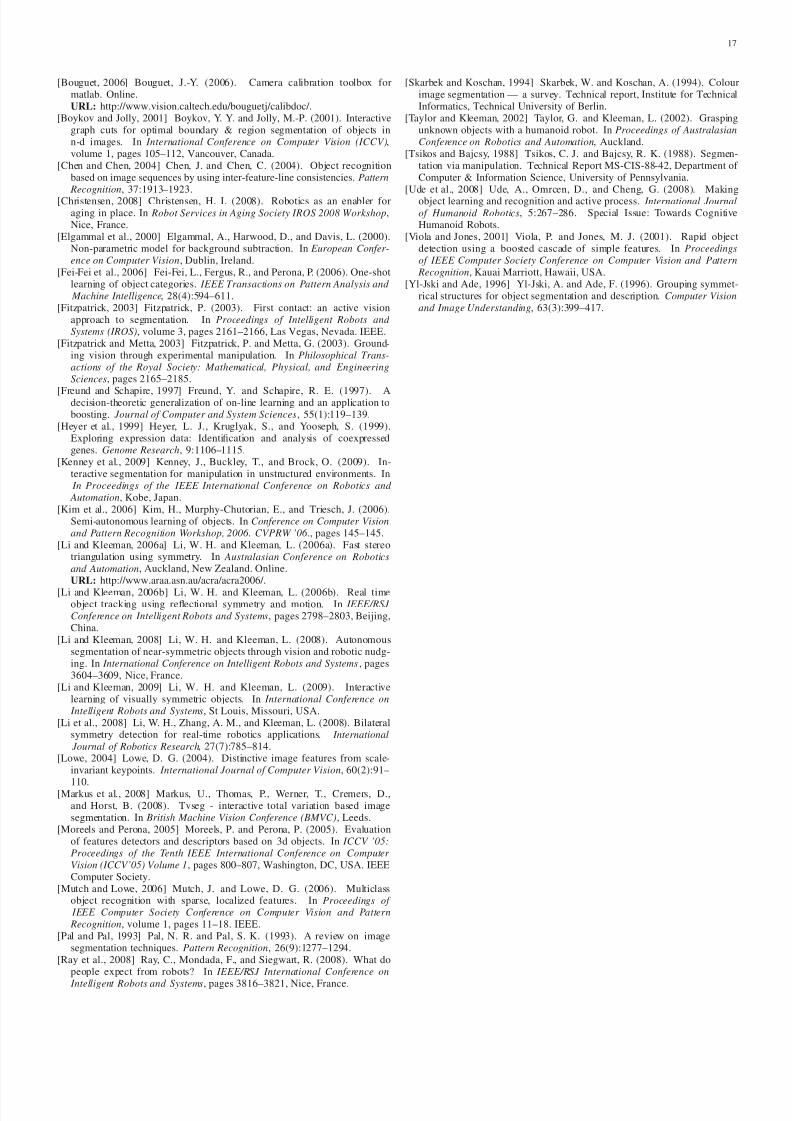
A stereotypical recognition result is shown in Figure 36(a).
The large number of SIFT matches centered around textured
areas is a general trend as seen in Figure 36(c). Our system
can also recognize objects that have undergone pose changes,
which is apparent in Figure 36(b). Notice the drop in number
of SIFT matches when the white bottle is turned upside down.
This may be caused by surface curvature, perspective effectsand changes in illuminations. The results in Figures 36(d) and
37(a) show that our recognition system is able to deal with
partial occlusion and background visual clutter. Note that the
brown bottle is also used to test the limits of recognition in
Section IX-E.
Figure 37(b) shows a small number of SIFT descriptor
matches for the glass bottle. This can be attributed to the
bottle’s reflective label and its low texture surface. Note that
a bad descriptor match can be seen between the bottle cap in
the input image and the label in the training image returned
by the system. Figures 37(c) and 37(d) show that the system
can recognize semi-transparent objects but also highlights the
fact that the object’s label is being recognized, not the object
itself. This can be seen in Figure 37(c) where an empty cola
bottle matches with the half-filled bottle in the database. The
reliance on object texture is an inherent limitation of SIFT
features and will be further investigated in Section IX-E
IX . EXPERIMENTS TO TES T LIMITS OF SYSTEM
The experiments presented in Section VIII were repeated in
another laboratory to test the system’s robustness to illumina-
tion changes and other factors. The robot arm was mounted
on a different table and the stereo cameras were placed at
a new location relative to the arm. Despite these changes,
following the calibration steps detailed in Section II-B allowed
the reconfiguration of a robust system. The newly configured
robotic system is shown in Figure 24.
The experiments presented tests some of the limits of our
autonomous system to examine its robustness and identify
failure modes. In each experimental subset, we aimed for
simple scenarios in order to control the number of parameters
that can vary. Experiments performed includes:
• Autonomous nudge and grasp of a mug with a handle to
test system on symmetric object with an asymmetry part
• Investigating the effects of background edge pixel noise
• Partial occlusion of the target object
• Object collisions during the robotic nudge
8/3/2019 Segmentation and Modelling of Visually SymmetricObjects by Robot Actions
http://slidepdf.com/reader/full/segmentation-and-modelling-of-visually-symmetricobjects-by-robot-actions 12/19
12
Fig. 24. Reconfigured robotic system. Note the different relative locations of the robot arm and cameras when compared against the old system in Figure 1
• Investigation of object recognition failure modes
Videos of the robot in action for the experiments above are
available from Extension 3. The first 4 sets of experimentsas listed above are presented in chronological order within the
video.Note that some object tracking videos have been slowed
down from 25FPS to 10FPS for ease of viewing. As object
recognition experiments are performed using passive vision no
videos are provided for them.
A. Symmetric objects with asymmetric parts
The robotic system was asked to learn a set of bottles using
a nudge then grasp approach in Section VIII-B. To see whether
the grasping approach generalized to symmetric objects with
asymmetric parts, a white mug with a handle was used totest the system. The robot was successful in nudging and
subsequently grasping the white mug. Figure 25 shows the
segmentation returned by the robot.
(a) Right camera image (b) Segmentation results
Fig. 25. Segmentation from autonomous nudge and grasp of white mug withhandle. Non-object pixels are coloured green in the segmentation result
B. Background edge pixel noise
Our robot’s reliance on bilateral symmetry is also its
Achilles heel, as multiple stages of visual processing make
use of our fast symmetry detector. The experiments presented
here attempt to disrupt the symmetry detection results by
introducing noisy edge pixels using a textured table cloth and
a newspaper. Recall from Figure 3 that our robotic system is
also designed to err on the side of caution and abort learning
attempts if anything goes wrong. As such, the experiments
also implicitly test the robustness of the system’s design.
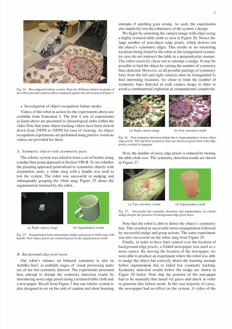
We begin by saturating the camera image with edges using
a highly textured table cloth as seen in Figure 26. Notice the
large number of non-object edge pixels, which drowns out
the object’s symmetric edges. This results in no interesting
locations being found by the robot as the triangulated symme-
try axes do not intersect the table in a perpendicular manner.The robot correctly chose not to attempt a nudge. It may be
possible to find the object by raising the number of symmetry
lines detected. However, as all possible pairings of symmetry
lines from the left and right cameras must be triangulated to
find interesting locations, we chose to limit the number of
symmetry lines detected in each camera image to three to
avoid a combinatorial explosion in computational complexity.
(a) Right camera image (b) Fast symmetry results
Fig. 26. Fast symmetry detection failure due to large quantities of non-objectedge pixels. The top three symmetry lines are shown as green lines with edgepixels overlaid in magenta
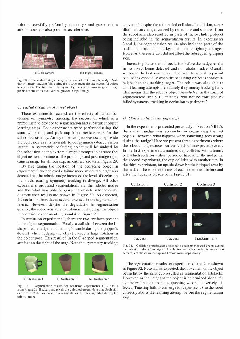
Next, the number of noisy edge pixels is reduced by turning
the table cloth over. The symmetry detection results are shown
in Figure 27.
(a) Fast symmetry results (b) Segmentation result
Fig. 27. Successful fast symmetry detection and segmentation via roboticnudge despite the presence of background edge pixel noise
Note that the robot is able to detect the object’s symmetry
line. This resulted in successful stereo triangulation followed
by successful nudge and grasp actions. The same experiment
was also successful on the white mug from Figure 25.
Finally, in order to have finer control over the location of
background edge pixels, a folded newspaper was used as a
noise source. By moving the location of the newspaper, we
were able to produce an experiment where the robot was able
to nudge the object but correctly aborts the learning attempt
before segmentation due to failed fast symmetry tracking.
Symmetry detection results before the nudge are shown in
Figure 28 below. Note that the position of the newspaper
had to be manually fine tuned via guess-and-check in order
to generate this failure mode. In the vast majority of cases,
the newspaper had no effect on the system. A video of the
8/3/2019 Segmentation and Modelling of Visually SymmetricObjects by Robot Actions
http://slidepdf.com/reader/full/segmentation-and-modelling-of-visually-symmetricobjects-by-robot-actions 13/19
13
robot successfully performing the nudge and grasp actions
autonomously is also provided as reference.
(a) Left camera (b) Right camera
Fig. 28. Successful fast symmetry detection before the robotic nudge. Notethat symmetry tracking fails during the robotic nudge despite successful objecttriangulation. The top three fast symmetry lines are shown in green. Edgepixels are shown in red over the grayscale input image
C. Partial occlusion of target object
These experiments focused on the effects of partial oc-
clusion on symmetry tracking, the success of which is aprerequisite to proceed to segmentation and subsequent object
learning steps. Four experiments were performed using the
same white mug and pink cup from previous tests for the
sake of consistency. An asymmetric object was used to provide
the occlusion as it is invisible to our symmetry-based vision
system. A symmetric occluding object will be nudged by
the robot first as the system always attempts to actuate the
object nearest the camera. The pre-nudge and post-nudge right
camera image for all four experiments are shown in Figure 29.
By fine tuning the location of the occluding object in
experiment 2, we achieved a failure mode where the target was
detected but the robotic nudge increased the level of occlusion
too much, causing symmetry tracking to diverge. All other
experiments produced segmentations via the robotic nudge
and the robot was able to grasp the objects autonomously.
Segmentation results are shown in Figure 30. As expected,
the occlusions introduced several artefacts in the segmentation
results. However, despite the degradation in segmentation
quality, the robot was able to autonomously grasp the object
in occlusion experiments 1, 3 and 4 in Figure 29.
In occlusion experiment 1, there are two artefacts present
in the object segmentation. Firstly, a collision between the L-
shaped foam nudger and the mug’s handle during the gripper’s
descent when nudging the object caused a large rotation in
the object pose. This resulted in the O-shaped segmentationartefact on the right of the mug. Note that symmetry tracking
(a) Occlusion 1 (b) Occlusion 3 (c) Occlusion 4
Fig. 30. Segmentation results for occlusion experiments 1, 3 and 4from Figure 29. Background pixels are coloured green. Note that Occlusionexperiment 2 did not produce a segmentation as tracking failed during the
robotic nudge
converged despite the unintended collision. In addition, scene
illumination changes caused by reflections and shadows from
the robot arm also resulted in parts of the occluding object
being included in the segmentation results. In experiments
3 and 4, the segmentation results also included parts of the
occluding object and background due to lighting changes.
However, these artefacts did not affect the subsequent grasping
step.Increasing the amount of occlusion before the nudge results
in no object being detected and no robotic nudge. Overall,
we found the fast symmetry detector to be robust to partial
occlusions especially when the occluding object is shorter in
height than the tracking target. The robot was also able to
abort learning attempts prematurely if symmetry tracking fails.
This means that the robot’s object knowledge, in the form of
segmentations and SIFT features, will not be corrupted by
failed symmetry tracking in occlusion experiment 2.
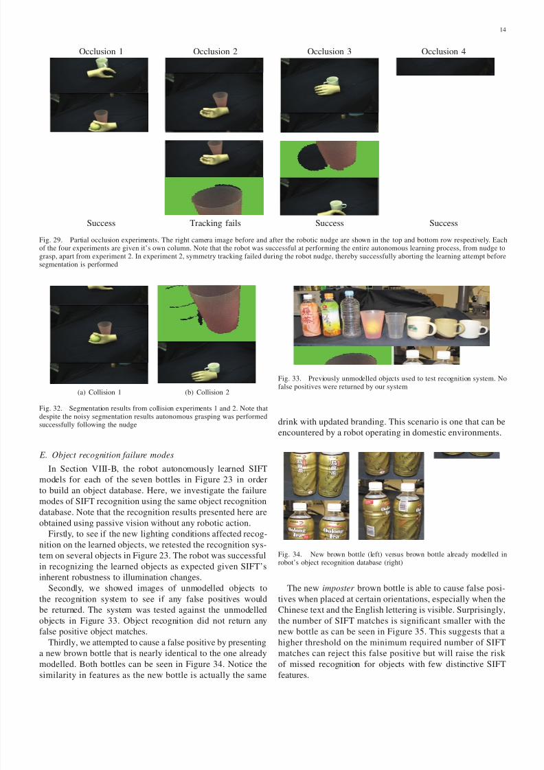
D. Object collisions during nudge
In the experiments presented previously in Section VIII-A,
the robotic nudge was successful in segmenting the test
objects. However, what happens when something goes wrong
during the nudge? Here we present three experiments where
the robotic nudge causes various kinds of unexpected events.
In the first experiment, a nudged cup collides with a tennis
ball which rolls for a short period of time after the nudge. In
the second experiment, the cup collides with another cup. In
the third experiment, an upside-down bottle is tipped over by
the nudge. The robot-eye-view of each experiment before and
after the nudge is presented in Figure 31.
Collision 1 Collision 2 Collision 3
Success Success Tracking fails
Fig. 31. Collision experiments designed to cause unexpected events duringthe robotic nudge (from right). The before and after nudge images (rightcamera) are shown in the top and bottom rows respectively.
The segmentation results for experiments 1 and 2 are shown
in Figure 32. Note that as expected, the movement of the object
being hit by the pink cup resulted in segmentation artefacts.
However, as the height of the object is determined along it’s
symmetry line, autonomous grasping was not adversely af-
fected. Tracking fails to converge for experiment 3 so the robot
correctly aborts the learning attempt before the segmentation
step.
8/3/2019 Segmentation and Modelling of Visually SymmetricObjects by Robot Actions
http://slidepdf.com/reader/full/segmentation-and-modelling-of-visually-symmetricobjects-by-robot-actions 14/19
14
Occlusion 1 Occlusion 2 Occlusion 3 Occlusion 4
Success Tracking fails Success Success
Fig. 29. Partial occlusion experiments. The right camera image before and after the robotic nudge are shown in the top and bottom row respectively. Eachof the four experiments are given it’s own column. Note that the robot was successful at performing the entire autonomous learning process, from nudge tograsp, apart from experiment 2. In experiment 2, symmetry tracking failed during the robot nudge, thereby successfully aborting the learning attempt beforesegmentation is performed
(a) Collision 1 (b) Collision 2
Fig. 32. Segmentation results from collision experiments 1 and 2. Note thatdespite the noisy segmentation results autonomous grasping was performedsuccessfully following the nudge
E. Object recognition failure modes
In Section VIII-B, the robot autonomously learned SIFT
models for each of the seven bottles in Figure 23 in order
to build an object database. Here, we investigate the failure
modes of SIFT recognition using the same object recognition
database. Note that the recognition results presented here are
obtained using passive vision without any robotic action.
Firstly, to see if the new lighting conditions affected recog-
nition on the learned objects, we retested the recognition sys-
tem on several objects in Figure 23. The robot was successful
in recognizing the learned objects as expected given SIFT’s
inherent robustness to illumination changes.
Secondly, we showed images of unmodelled objects to
the recognition system to see if any false positives would
be returned. The system was tested against the unmodelled
objects in Figure 33. Object recognition did not return any
false positive object matches.
Thirdly, we attempted to cause a false positive by presenting
a new brown bottle that is nearly identical to the one already
modelled. Both bottles can be seen in Figure 34. Notice the
similarity in features as the new bottle is actually the same
Fig. 33. Previously unmodelled objects used to test recognition system. Nofalse positives were returned by our system
drink with updated branding. This scenario is one that can be
encountered by a robot operating in domestic environments.
Fig. 34. New brown bottle (left) versus brown bottle already modelled inrobot’s object recognition database (right)
The new imposter brown bottle is able to cause false posi-
tives when placed at certain orientations, especially when the
Chinese text and the English lettering is visible. Surprisingly,
the number of SIFT matches is significant smaller with the
new bottle as can be seen in Figure 35. This suggests that a
higher threshold on the minimum required number of SIFT
matches can reject this false positive but will raise the risk
of missed recognition for objects with few distinctive SIFT
features.
8/3/2019 Segmentation and Modelling of Visually SymmetricObjects by Robot Actions
http://slidepdf.com/reader/full/segmentation-and-modelling-of-visually-symmetricobjects-by-robot-actions 15/19
15
(a) Old modelled bottle (b) New bottle
Fig. 35. Example of false positive caused by the new imposter brown bottle. Note the reduced number of SIFT matches as compared to the old bottle alreadymodelled in the recognition database
F. Discussion of limitations
The experiments in this section highlight the strengths and
weaknesses of our system. As the experiments were conducted
in a different laboratory, they suggest that the proposed design
is robust to illumination changes as well as changes in arm-
camera geometry and camera-table viewpoint. Table II lists
the chance of different failure modes as experienced during
the robotic experiments. A horizontal dash indicates that
tracking is not performed as no symmetric objects are detected.
Note that the object recognition experimental results are not
included in the table as they do not make use of the whole
system.
TABLE IICHANCE OF SYSTEM FAILURE ACCORDING TO EXPERIMENTAL RESULTS
ExperimentFailure mode
No object detected Tracking diverges
Asymmetric parts Rare Rare
High background texture Common -
Some background texture Rare Rare
Textured background distractor Rare Sometimes
Minor occlusion Rare Rare
Major occlusion pre-nudge Common -
Major occlusion post-nudge Rare Common
Collision Rare Rare
Object tipping over Rare Common
Here we define failure mode as the manner in which ourrobotic system aborts object segmentation and modelling,
which does not imply complete failure of the system. As can
be seen in Table II, experiments revealed that our system has
two main modes of failure in the learning process described in
Figure 3. Firstly, object detection can fail due to overwhelming
background edge noise or the lack of object edge pixels caused
by occlusion. This results in the system stopping the object
learning process before any robotic action. Secondly, given
that an object is detected by the robot, fast symmetry tracking
can diverge during the robotic nudge. Tracking failure can be
caused by occlusion of the target object, the nudged object
being tipped over or the presence of background symmetrylines along the moving object’s trajectory. Again, the robot
will err on the side of caution by stopping the learning process
and abandoning the motion segmentation attempt. Overall,
our action-based learning approach appears to be robust to
unexpected events.
The first two collision experiments did not interrupt the
learning process but introduced artefacts in the segmentation
results. These artefacts did not affect subsequent grasping but
one can imagine scenarios with complicated object clutter
that may result in a failed grasp or further collisions between
the gripper and non-target objects. Unintentionally, the robot
gripper also collided with the white mug in the occlusion
8/3/2019 Segmentation and Modelling of Visually SymmetricObjects by Robot Actions
http://slidepdf.com/reader/full/segmentation-and-modelling-of-visually-symmetricobjects-by-robot-actions 16/19
16
experiment 1. This resulted in a large rotation of the object
and a segmentation artefact. The system was able to track the
nudged object and complete the learning process despite this
problem. However, due to the white mug’s lack of texture, the
SIFT features extracted during the learning process may not
be of great use for object recognition.
SIFT object recognition was robust and some effort was
needed to generate the failure modes. A near-identical bottlewas needed to cause false positives. The use of robotic action,
such as grasping and rotating an object to access more views,
may help disambiguate highly similar objects and prevent
false positives. Missed detection required significant removal
of features. Further investigation of failure modes as well as
the synergistic use of other features such as colour and edge
contours for object modelling are interesting directions for
future work.
X. CONCLUSIONS AND FUTURE WOR K
Our interactive segmentation approach performs robustly
and accurately on near-symmetric objects in visually clutteredenvironments. By using the robotic nudge, the entire segmen-
tation process is carried out autonomously. Multi-coloured and
transparent objects, as well as objects with asymmetric parts,
are handled in a robust manner. We have shown that our
approach can segment objects of various visual appearances,
which will help shift the burden of training image collection
from the user to the robot.
End effector obstacle avoidance and path planning, espe-
cially in situations where non-symmetric objects are present in
the robotic nudge path, are left to future work. Object detection
is a prerequisite for path planning and path planning is needed
to actuate objects in cluttered scenes. Careful application of therobotic nudge may help resolve this chicken-and-egg problem.
Improvements can also be made to the motion segmentation
approach. Section IX showed that the reliance on edges for
symmetry detection is a limitation of our system. The use
of orthogonal visual modalities such as colour and intensity
gradients maybe synergistic to our segmentation approach.
Stereo optical flow and graph cuts may improve the quality of
segmentation but sacrifices the system’s ability to operate on
transparent and reflective objects as these objects lack reliable
surface information. As the geometry of our table plane is
known, dense stereo can provide further improvements by
removing the nudged object’s shadow from the segmentation
results.
After carrying out object segmentation autonomously, our
robot continues to learn about new objects through physical
interaction. Our robot is able leverage a simple nudge action
to pick up and rotate new objects. Experiments show that our
robot is able pick up beverage bottles autonomously, including
a transparent plastic bottle and a fragile glass bottle. This
raises the question of whether other objects can be modelled
using our nudge-then-grasp approach. Household objects such
as vases, mugs, tin cans, jugs, pots, baskets, buckets are
sufficiently symmetric for our vision algorithms. Whether the
power-grasp employed for bottles will generalize to these
objects poses an interesting prospect for future work. For
example, cutlery can be sensed using visual symmetry [Yl-Jski
and Ade, 1996], but requires different manipulation strategies
to actuate. The use of other visual features that represent object
structure, such as radial symmetry or rectilinear box models,
may also lend themselves to a nudge-then-grasp approach.
The concept of moving from simple to more advanced
object manipulations allows a robot to autonomously escalate
object interactions. Our robot was able to construct a smalldatabase of objects that is sufficient for robust recognition
without any human intervention. Experimental results suggests
that robot-collected training data is of sufficient quality to
build useful object models. The inclusion of other features,
such as colour histograms and object contours may increase
the discriminatory power of the learned object models as
well as compensate for SIFT’s reliance on surface texture.
Online estimation of the fundamental matrix between views
of the grasped object and structure from motion may enable
the construction of 3D object models. Robot-learned object
models may also enable more intelligent regrasping of learned
objects.
Our robot is an addition to a sparse field of systems [Fitz-
patrick, 2003], [Ude et al., 2008], [Kenney et al., 2009] that
actuates objects in front of a static camera instead of actuating
a camera around static objects. The proposed approach takes
a small but important step towards greater robot autonomy by
shifting the labour intensive tasks of training data collection
and object learning from the human user to the tireless robot.
Given the ever increasing ratio of workers versus retirees in
many industrial nations [Christensen, 2008] and positive public
opinion towards domestic robots [Ray et al., 2008], the case for
autonomous object learning via robotic interaction has never
been stronger.
APPENDIX: INDEX TO MULTIMEDIA EXTENSIONS
TABLE IIIINDEX TO MULTIMEDIA EXTENSIONS
Extension Media Type Description
1 Vid eo Object segmentatio n by robotic nudge
2 Video Object modelling using SIFT
3 Video Experiments to test system limits
ACKNOWLEDGEMENTS
Thanks go to Steve Armstrong for his help with repair-
ing the PUMA 260 manipulator. We gratefully acknowledge
Monash IRRC for their financial support. The authors also
thank the anonymous reviewers for their insightful comments
and the suggestion to further experiment with the limits of our
robotic system. The work presented in this paper was funded
by the ARC Centre for Perceptive and Intelligent Machines in
Complex Environments (CE0561489).
REFERENCES
[Arun et al., 1987] Arun, K. S., Huang, T. S., and Blostein, S. D. (1987).Least-squares fitting of two 3-d point sets. IEEE Transactions on Pattern
Analysis and Machine Intelligence, 9:698–700.
8/3/2019 Segmentation and Modelling of Visually SymmetricObjects by Robot Actions
http://slidepdf.com/reader/full/segmentation-and-modelling-of-visually-symmetricobjects-by-robot-actions 17/19
17
[Bouguet, 2006] Bouguet, J.-Y. (2006). Camera calibration toolbox formatlab. Online.URL: http://www.vision.caltech.edu/bouguetj/calibdoc/.
[Boykov and Jolly, 2001] Boykov, Y. Y. and Jolly, M.-P. (2001). Interactivegraph cuts for optimal boundary & region segmentation of objects inn-d images. In International Conference on Computer Vision (ICCV),volume 1, pages 105–112, Vancouver, Canada.
[Chen and Chen, 2004] Chen, J. and Chen, C. (2004). Object recognitionbased on image sequences by using inter-feature-line consistencies. Pattern
Recognition, 37:1913–1923.[Christensen, 2008] Christensen, H. I. (2008). Robotics as an enabler for
aging in place. In Robot Services in Aging Society IROS 2008 Workshop,Nice, France.
[Elgammal et al., 2000] Elgammal, A., Harwood, D., and Davis, L. (2000).Non-parametric model for background subtraction. In European Confer-
ence on Computer Vision, Dublin, Ireland.[Fei-Fei et al., 2006] Fei-Fei, L., Fergus, R., and Perona, P. (2006). One-shot
learning of object categories. IEEE Transactions on Pattern Analysis and
Machine Intelligence, 28(4):594–611.[Fitzpatrick, 2003] Fitzpatrick, P. (2003). First contact: an active vision
approach to segmentation. In Proceedings of Intelligent Robots and
Systems (IROS), volume 3, pages 2161–2166, Las Vegas, Nevada. IEEE.[Fitzpatrick and Metta, 2003] Fitzpatrick, P. and Metta, G. (2003). Ground-
ing vision through experimental manipulation. In Philosophical Trans-
actions of the Royal Society: Mathematical, Physical, and Engineering
Sciences, pages 2165–2185.
[Freund and Schapire, 1997] Freund, Y. and Schapire, R. E. (1997). Adecision-theoretic generalization of on-line learning and an application toboosting. Journal of Computer and System Sciences, 55(1):119–139.
[Heyer et al., 1999] Heyer, L. J., Kruglyak, S., and Yooseph, S. (1999).Exploring expression data: Identification and analysis of coexpressedgenes. Genome Research, 9:1106–1115.
[Kenney et al., 2009] Kenney, J., Buckley, T., and Brock, O. (2009). In-teractive segmentation for manipulation in unstructured environments. In
In Proceedings of the IEEE International Conference on Robotics and
Automation, Kobe, Japan.[Kim et al., 2006] Kim, H., Murphy-Chutorian, E., and Triesch, J. (2006).
Semi-autonomous learning of objects. In Conference on Computer Vision
and Pattern Recognition Workshop, 2006. CVPRW ’06., pages 145–145.[Li and Kleeman, 2006a] Li, W. H. and Kleeman, L. (2006a). Fast stereo
triangulation using symmetry. In Australasian Conference on Robotics
and Automation, Auckland, New Zealand. Online.URL: http://www.araa.asn.au/acra/acra2006/.
[Li and Kleeman, 2006b] Li, W. H. and Kleeman, L. (2006b). Real timeobject tracking using reflectional symmetry and motion. In IEEE/RSJ
Conference on Intelligent Robots and Systems, pages 2798–2803, Beijing,China.
[Li and Kleeman, 2008] Li, W. H. and Kleeman, L. (2008). Autonomoussegmentation of near-symmetric objects through vision and robotic nudg-ing. In International Conference on Intelligent Robots and Systems , pages3604–3609, Nice, France.
[Li and Kleeman, 2009] Li, W. H. and Kleeman, L. (2009). Interactivelearning of visually symmetric objects. In International Conference on
Intelligent Robots and Systems, St Louis, Missouri, USA.[Li et al., 2008] Li, W. H., Zhang, A. M., and Kleeman, L. (2008). Bilateral
symmetry detection for real-time robotics applications. International
Journal of Robotics Research, 27(7):785–814.[Lowe, 2004] Lowe, D. G. (2004). Distinctive image features from scale-
invariant keypoints. International Journal of Computer Vision, 60(2):91–
110.[Markus et al., 2008] Markus, U., Thomas, P., Werner, T., Cremers, D.,and Horst, B. (2008). Tvseg - interactive total variation based imagesegmentation. In British Machine Vision Conference (BMVC), Leeds.
[Moreels and Perona, 2005] Moreels, P. and Perona, P. (2005). Evaluationof features detectors and descriptors based on 3d objects. In ICCV ’05:
Proceedings of the Tenth IEEE International Conference on Computer
Vision (ICCV’05) Volume 1, pages 800–807, Washington, DC, USA. IEEEComputer Society.
[Mutch and Lowe, 2006] Mutch, J. and Lowe, D. G. (2006). Multiclassobject recognition with sparse, localized features. In Proceedings of
IEEE Computer Society Conference on Computer Vision and Pattern
Recognition, volume 1, pages 11–18. IEEE.[Pal and Pal, 1993] Pal, N. R. and Pal, S. K. (1993). A review on image
segmentation techniques. Pattern Recognition, 26(9):1277–1294.[Ray et al., 2008] Ray, C., Mondada, F., and Siegwart, R. (2008). What do
people expect from robots? In IEEE/RSJ International Conference on
Intelligent Robots and Systems, pages 3816–3821, Nice, France.
[Skarbek and Koschan, 1994] Skarbek, W. and Koschan, A. (1994). Colourimage segmentation — a survey. Technical report, Institute for TechnicalInformatics, Technical University of Berlin.
[Taylor and Kleeman, 2002] Taylor, G. and Kleeman, L. (2002). Graspingunknown objects with a humanoid robot. In Proceedings of Australasian
Conference on Robotics and Automation, Auckland.[Tsikos and Bajcsy, 1988] Tsikos, C. J. and Bajcsy, R. K. (1988). Segmen-
tation via manipulation. Technical Report MS-CIS-88-42, Department of Computer & Information Science, University of Pennsylvania.
[Ude et al., 2008] Ude, A., Omrcen, D., and Cheng, G. (2008). Makingobject learning and recognition and active process. International Journal
of Humanoid Robotics, 5:267–286. Special Issue: Towards CognitiveHumanoid Robots.
[Viola and Jones, 2001] Viola, P. and Jones, M. J. (2001). Rapid objectdetection using a boosted cascade of simple features. In Proceedings
of IEEE Computer Society Conference on Computer Vision and Pattern
Recognition, Kauai Marriott, Hawaii, USA.[Yl-Jski and Ade, 1996] Yl-Jski, A. and Ade, F. (1996). Grouping symmet-
rical structures for object segmentation and description. Computer Vision
and Image Understanding, 63(3):399–417.
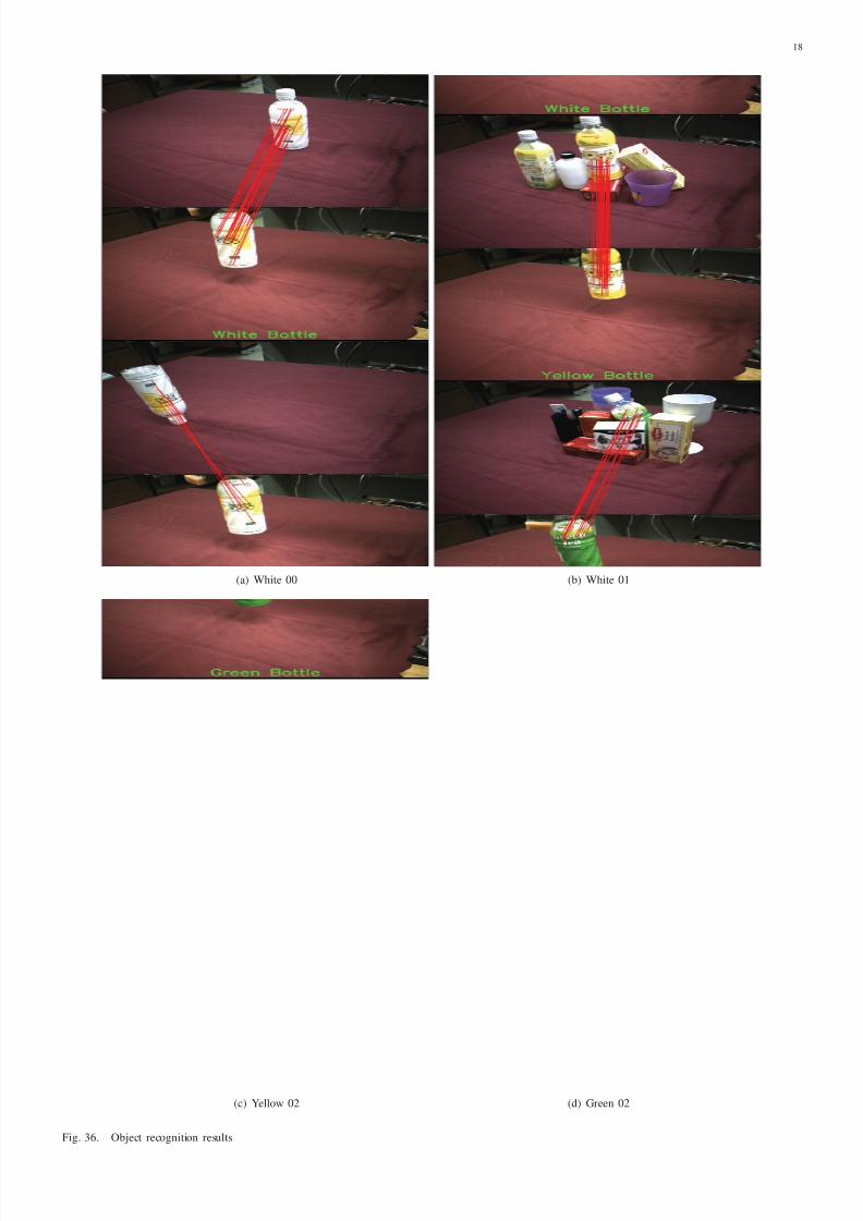
8/3/2019 Segmentation and Modelling of Visually SymmetricObjects by Robot Actions
http://slidepdf.com/reader/full/segmentation-and-modelling-of-visually-symmetricobjects-by-robot-actions 18/19
18
(a) White 00 (b) White 01
(c) Yellow 02 (d) Green 02
Fig. 36. Object recognition results
8/3/2019 Segmentation and Modelling of Visually SymmetricObjects by Robot Actions
http://slidepdf.com/reader/full/segmentation-and-modelling-of-visually-symmetricobjects-by-robot-actions 19/19
19
(a) Brown 03 (b) Glass 03
(c) Cola 03 (d) Semi-Transparent 03
Fig. 37. Object recognition results