serie 94 700 - gebrueder-prinz.de · safety start and stop instructions instructions de mise en...
TRANSCRIPT
MANUALE D’USO E MANUTENZIONE Codice 90103053 Edizione
OWNER’S MANUAL Code 90103053 Edition
MANUEL D’ENTRETIEN Code 90103053 Edition 11.10
MANUAL DE USO Y MANTENIMIENTO Codigo 90103053 Edición
WARTUNGSANLEITUNG Kodezahl 90103053 Ausgabe
BCS S.p.A.BCS S.p.A.BCS S.p.A.BCS S.p.A. –––– V.le Mazzini, 161 V.le Mazzini, 161 V.le Mazzini, 161 V.le Mazzini, 161 –––– 20081 ABBIATEGRASSO 20081 ABBIATEGRASSO 20081 ABBIATEGRASSO 20081 ABBIATEGRASSO –––– MI MI MI MI –––– Italia Italia Italia Italia
• MOTOCOLTIVATORIMOTOCOLTIVATORIMOTOCOLTIVATORIMOTOCOLTIVATORI
• TWOTWOTWOTWO----WHEEL TRACTORSWHEEL TRACTORSWHEEL TRACTORSWHEEL TRACTORS
• MOTOCULTEURSMOTOCULTEURSMOTOCULTEURSMOTOCULTEURS Mod.
• MOTOCULTORESMOTOCULTORESMOTOCULTORESMOTOCULTORES
• EINACEINACEINACEINACHSERHSERHSERHSER
serie 94700
710 – 720 – 730 710 GARDENER
712 RENTAL
718 HARVESTER 722 HARVESTER 732 PROFESSIONAL
serie 700

ADESIVI PER LA SICUREZZA / LABELS WITH SAFETY INSTRUCTIONS / ADHÉSIFS POUR LA SÉCURITÉ / ADHESIVOS PARA LA SEGURIDAD / SICHERHEITSSELBSTKLEBER
ISTRUZIONE DI AVVIAMENTO E STOP CON SICUREZZA SAFETY START AND STOP INSTRUCTIONS
INSTRUCTIONS DE MISE EN MARCHE ET ARRET AVEC SECURITE INSTRUCCIONES DE PUESTA EN MARCHA Y PARADA CON SEGURIDAD
START- UND STOPSICHERHEITSANWEISUNGEN
INDICAZIONE DI ZONA SURRISCALDATA OVERHEATING AREA WARNING
INDICATION DE ZONE SURCHAUFFEE INDICACIÓN DE ZONA SOBRECALENTADA SIGNALISIERUNG ÜBERHITZTER BEREICH
PERICOLO PER RIFORNIMENTO DANGER: APPLY SAFETY PRECAUTIONS WHEN REFUELLING
DANGER A CAUSE DE PLEIN DE CARBURANT MÁXIMA PRECAUCIÓN DURANTE EL REABASTECIMIENTO DE COMBUSTIBLE
GEFAHR BEIM AUFTANKEN

MANUALE D’USO E MANUTENZIONE Codice 90103053 Edizione
OWNER’S MANUAL Code 90103053 Edition
MANUEL D’ENTRETIEN Code 90103053 Edition 11.10
MANUAL DE USO Y MANTENIMIENTO Codigo 90103053 Edición
WARTUNGSANLEITUNG Kodezahl 90103053 Ausgabe
BCS S.p.A. BCS S.p.A. BCS S.p.A. BCS S.p.A. –––– V.le Mazzini, 161 V.le Mazzini, 161 V.le Mazzini, 161 V.le Mazzini, 161 –––– 20081 ABBIATEGRASSO 20081 ABBIATEGRASSO 20081 ABBIATEGRASSO 20081 ABBIATEGRASSO –––– MI MI MI MI –––– Italia Italia Italia Italia
• MOTOCOLTIVATORIMOTOCOLTIVATORIMOTOCOLTIVATORIMOTOCOLTIVATORI
• TWOTWOTWOTWO----WHEEL TRACTORSWHEEL TRACTORSWHEEL TRACTORSWHEEL TRACTORS
• MOTOCULTEURSMOTOCULTEURSMOTOCULTEURSMOTOCULTEURS Mod.
• MOTOCULTORESMOTOCULTORESMOTOCULTORESMOTOCULTORES
• EINACHSEREINACHSEREINACHSEREINACHSER
serie 94700
710 – 720 – 730 710 GARDENER
712 RENTAL
718 HARVESTER 722 HARVESTER 732 PROFESSIONAL
serie 700

4
I
Le macchine comprese in questo manuale sono costruite in accordo con la Direttiva Macchine Europea e sue modificazioni.
La società BCS si complimenta con Voi per la scelta di un nostro prodotto garantendoVi il massimo dell'assistenza e della collaborazione che da sempre contraddistinguono il nostro marchio. Questa pubblicazione Vi aiuterà a conoscere meglio la Vo-stra macchina. Se verrà usata seguendo queste istruzioni Vi durerà molti anni e Vi sarà di prezioso aiuto per svolgere i Vostri lavori agricoli. Vi raccomandiamo pertanto di leggere attentamente que-ste pagine e di seguirne sempre i consigli.
GB
The machines described in this manual are built in accordance with the European
Machines Directive and its modifications.
BCS congratulates with You for Your purchasing a machi-ne from our range. We will grant the assistance and coope-ration which have always been a feature of our products. If use in accordance with the instructions contained in your owners manual, your machine will last many years and will prove to be of an invaluable assistance to you. We therefore recommend that You read the manual carefully and follow the advice given.
F
Les machines décrites dans ce manuel sont construites en accord avec la Directive
Européenne des Machines et ses modifications.
La société BCS Vous félicite pour le choix d’un de nos produit en Vous assurant le maximum de notre assistance et collaboration qui ont toujours distingué notre marque. Cette publication Vous aidera à mieux connaître Votre ma-chine. Si Vous l'utilisez conformément aux instructions contenues dans ce manuel,il durera de nombreuses années et sera pour Vous une aide précieuse pour Vos travaux agricoles. Nous Vous recommandons, par conséquent, de lire ces pages avec attention et de suivre scrupuleusement les conseils.
E
Las máquinas incluidas en este manual están construidas según la Directriz
Europea de las máquinas y sus enmiendas.
La sociedad BCS se alegra con Usted por haber escogido nuestro producto. BCS puede asegurar la maxima asisten-cia y collaboración que siempre han caracterizado nuestra marca. Este libro le ayudará a conocer mejor su máquina. Si la usa siguiendo estas instrucciones le durerá muchos años y la será de gran ayuda para desarrollar sus trabajo agríco-las. Le recomendamos pues, leer atentamente estas páginas y seguir siempre los consejos que ellas encontrarà.
D
Die in dem vorliegenden Handbuch beschriebenen Maschinen sind der
Europäische Richtlinie über Maschinen und ihren Abänderungen gemäß gebaut worden.
BCS erfreut sich um Ihre Wahl. Unsere Firma wird zweifel-los Ihnen seine beste Wartung und Zusammenarbeit bie-ten, die seit immer BCS-Produkte kennzeichen. Wenn Sie in diesem Handbuch erteilten Anleitungen be-herzigen, wird Ihre Maschine über lange Zeit eine wertvolle Hilfe sein. Bitte lesen Sie daher vorliegende Bedienungsanleitung aufmerksam durch und befolgen Sie die erteilten Ratsch-läge.
5
INDICE
I
IDENTIFICAZIONE E MARCATURA SIMBOLOGIA AVVERTENZE INFORMAZIONI PER L'OPERATORE MOTOCOLTIVATORI MONTAGGIO DELLA MACCHINA NORME DI SICUREZZA DESCRIZIONE DEI COMANDI APPLICAZIONE ATTREZZI PRESA DI POTENZA CONTROLLI DA ESEGUIRE AVVIAMENTO DELLA MACCHINA
Pag. 7 “ 9 “ 9 “ 11 “ 12 “ 15 “ 16 “ 19 “ 22 “ 24 “ 26 “ 27
AVVIAMENTO ELETTRICO LUBRIFICAZIONE E MANUTENZIONE TABELLA 1 : RUOTE TABELLA 2 : MOTORI TABELLA 3 : VELOCITA' CARATTERISTICHE TECNICHE ATTREZZI APPLICABILI ACCESSORI ATTREZZI ED ACCESSORI SPECIALI ARATRI ASSOLCATORE RETROFRESA ASSOLCATORE REGISTRABILE CARRELLO DI TRASFERIMENTO
Pag. 30 “ 31 “ 33 “ 34 “ 34 “ 35 “ 36 “ 37 “ 37 “ 41
“ 42 “ 44 “ 45
INDEX
GB
IDENTIFICATION AND TAGGING SYMBOLS WARNINGS INFORMATION FOR USER TWO-WHEEL TRACTORS MACHINE ASSEMBLY GENERAL SAFETY CONTROL DESCRIPTION IMPLEMENT ASSEMBLY P.T.O. CHECKS BEFORE STARTING THE MACHINE TO START THE MACHINE
Page 7 “ 9 “ 9 “ 11 “ 12 “ 15 “ 16 “ 19 “ 22 “ 24 “ 26 “ 27
ELECTRIC STARTER LUBRICATION AND MAINTENANCE TABLE 1 : WHEELS TABLE 2 : ENGINES TABLE 3 : SPEEDS TECHNICAL FEATURES POSSIBLE IMPLEMENTS ACCESSORIES SPECIAL IMPLEMENTS AND ACCESSORIES PLOUGHS RIDGER ADAPTABLE BEHIND ROTARY HOE ADJUSTABLE RIDGER MOVING SULKY
Page 30 “ 31 “ 33 “ 34 “ 34 “ 35 “ 36 “ 37 “ 37 “ 41
“ 42 “ 44
“ 45
CONTENU
F
IDENTIFICATION ET MARQUAGE SYMBOLES RECOMMANDATIONS INFORMATIONS POUR L'OPÉRATEUR MOTOCULTEURS MONTAGE DE LA MACHINE REGLES DE SECURITE GENERALE DESCRIPTION DES COMMANDES MONTAGE OUTILS PRISE DE PUISSANCE CONTROLES A EFFECTUER DEMARRAGE DE LA MACHINE
Page 7 “ 9 “ 9 “ 11 “ 12 “ 15 “ 16 “ 19 “ 22 “ 24 “ 26 “ 27
DEMARRAGE ELECTRIQUE LUBRIFICATION ET ENTRETIEN TABLEAU 1 : ROUES TABLEAU 2 : MOTEURS TABLEAU 3 : VITESSES CARACTERISTIQUES TECHNIQUES OUTILS ADAPTABLES ACCESSOIRES OUTILS AND ACCESSOIRES SPECIAUX CHARRUES BUTTOIR MONTE DERRIERE LA FRAISE BUTTOIR A AILES REGLABLES SULKY DE DEPLACEMENT
Page 30 “ 31 “ 33 “ 34 “ 34 “ 35 “ 36 “ 37 “ 37 “ 41
“ 42 “ 44
“ 45
INDICE
E
IDENTIFICACIÓN Y MARCAS SIMBOLOGÍA ADVERTENCIAS INFORMACCIONES PARA EL UTILIZADOR MOTOCULTORES MONTAJE DE LA MAQUINA NORMAS DE SEGURIDAD DESCRIPCION DE LOS MANDOS APLICACION APEROS TOMA DE FUERZA CONTROLES A EFECTUAR ARRANQUE DE LA MAQUINA
Pag. 7 “ 9 “ 9 “ 11 “ 12 “ 15 “ 16 “ 19 “ 22 “ 24 “ 26 “ 27
ARRANQUE ELECTRICO LUBRICACION Y MANTENIMIENTO TABLA 1 : RUEDAS TABLA 2 : MOTORES TABLA 3 : VELOCIDADES CARACTERISTICAS TECNICAS APEROS APLICABLES ACCESSORIOS APEROS Y ACCESSORIOS ESPECIALES ARADOS SURCADOR RETROFRESA SURCADOR REGISTRABLE CARRO DE TRANSPORTE
Pag. 30 “ 31 “ 33 “ 34 “ 34 “ 35 “ 36 “ 37 “ 37 “ 41
“ 42 “ 44 “ 45
D
IDENTIFIZIERUNG UND MARKIERUNG SYMBOLE BEMERKUNGEN INFORMATIONEN FÜR DER OPERATOR EINÄCHSER MASCHINENMONTAGE SICHERHEITSVORSCHRIFTEN BESCHREIBUNG DER BEDIENUNGSORGANE MONTAGE DER ARBEITSGERÄTE ZAPFWELLE VOR DER INBETRIEBNAHME INBETRIEBNAHME DER MASCHINE
Seite 7 ” 9 ” 9 ” 11 ” 12 ” 15 ” 16 ” 19 ” 22 ” 24 ” 26 ” 27
ELEKTROSTARTER SCHMIERUNG UND WARTUNG TAFEL 1 : RÄDER TAFEL 2 : MOTOREN TAFEL 3 : GESCHWINDIGKEITEN TECNISCHE EIGENSCHAFTEN MÖGLICHE ARBEITSGERÄTE ZUBEHÖR SPEZIELLE ARBEITSGERÄTE UND ZUBEHÖR PFLÜGE FURCHENZIEHER HINTER DER FRÄSE VERSTELLBARER FURCHENZIEHER TRANSPORTSITZWAGEN
Seite 30 ” 31 ” 33 ” 34 ” 34 ” 35 ” 36 ” 37 ” 37 ” 41
” 42 ” 44
” 45

6
I
CARRELLO DI LAVORO RIMORCHIO A RUOTE LIBERE RUOTE PNEUMATICHE RUOTE METALLICHE A GABBIA RUOTE “SUPER-BITE” GEMELLAGGIO RUOTE DISTANZIALI PER RUOTE ZAVORRE PER RUOTE ZAVORRA PER BARRA ATTACCO CURVO RUOTINO SOSTEGNO FRESA PROTEZIONE ANTERIORE PER BARRA PROTEZIONI LATERALI PER BARRA
Pag. 45 ” 47 ” 48 ” 50 ” 50 ” 51 ” 52 ” 54 ” 54 ” 55 ” 55 ” 56 ” 56
ATTACCO RAPIDO ATTREZZI PRESA DI FORZA UNIFICATA D=35 CATENE DA NEVE FRENO POSSIBILI INCONVENIENTI E LORO RIMEDI PERIODI DI LUNGA INATTIVITA' DOTAZIONE GARANZIA CERTIFICATI E DICHIARAZIONI PARTICOLARI DI CONSUMO MODALITA' DI VENDITA DEI RICAMBI COME SOSTITUIRE LA FRIZIONE (figura 69)
Pag. 58 ” 59 ” 59 ” 60 ” 62 ” 65 ” 66 ” 66 ” 67 ” 68 ” 69 ” 70
GB
WORKING SULKY TRAILER WITH FREE WHEELS PNEUMATIC WHEELS STEEL CAGE WHEELS WHEELS “SUPER-BITE” WHEELS TWINNING WHEEL SPACERS BALLASTS FOR WHEELS BALLAST FOR CUTTER BAR (27 lbs) COURVED COUPLING ROTARY HOE WHEEL CUTTER BAR FRONT PROTECTIONS CUTTER BARS SIDE PROTECTIONS
Page 45 ” 47 ” 48 ” 50 ” 50 ” 51 ” 52 ” 54 ” 54 ” 55 ” 55 ” 56 ” 56
QUICK HITCH FOR IMPLEMENTS STANDARD POWER TAKE OFF D=35 SNOW CHAINS BRAKE TROUBLE SHOOTING STORAGE TOOL KIT GUARANTEE CERTIFICATES AND DECLARATIONS CONSUMABLES ORDERING SPARE PARTS HOW TO REPLACE THE CLUTCH (picture 69)
Page 58 ” 59 ” 59 ” 60 ” 62 ” 65 ” 66 ” 66 ” 67 ” 68 ” 69 ” 70
F
SULKY DE TRAVAIL REMORQUE A ROUES LIBRES ROUES PNEUMATIQUE ROUES METALLIQUES ROUES “SUPER-BITE” JUMELAGE ROUES ENTRETOISES POUR ROUES LEST POUR ROUES LEST POUR BARRE (kg. 12) ATTACHE COURBE ROUE PORTEUSE POUR FRAISE PROTECTION AVANT POUR BARRE PROTECTIONS LATERALES POUR BARRES
Page 45 ” 47 ” 48 ” 50 ” 50 ” 51 ” 52 ” 54 ” 54 ” 55 ” 55 ” 56 ” 56
ENGANCHE RAPIDE OUTILS PRISE DE FORCE UNIFIÉE D=35 CHAINES NEIGE FREIN DEPANNAGE REMISAGE OUTILLAGE GARANTIE CERTIFICATS ET DÉCLERATIONS SUYET A USURE MODALITE DE VENT DES PIECES DE RECHANGE COMMENT SUBSTITUER LA FRICTION (fig.69)
Page 58 ” 59 ” 59 ” 60 ” 62 ” 65 ” 66 ” 66 ” 67 ” 68 ” 69 ” 70
E
CARRO DE TRABAJO REMOLQUE DE ARRASTRE RUEDAS NEUMATICAS RUEDAS DE JAULA RUEDAS “SUPER-BITE” RUEDAS GEMELAS DISTANCIALES PARA RUEDAS LASTRES PARA RUEDAS CONTRAPESO PARA BARRA (kg. 12) ATAQUE CURVO RUEDA SOPORTE FRESA PROTECCION ANTERIOR PARA BARRA PROTECCIONES LATERALES PARA BARRAS
Pag. 45 ” 47 ” 48 ” 50 ” 50 ” 51 ” 52 ” 54 ” 54 ” 55 ” 55 ” 56 ” 56
ENGANCHE RAPIDO APEROS TOMA DE FUERZA UNIFICADA D=35 CADENAS PARA NIEVE FRENO POSIBLES INCONVENIENTES Y SOLUCIONES PERIODOS DE LARGA INACTIVIDAD DOTACIONES GARANTIA CERTIFICADOS Y DECLARACIONES PARTICULARES DE DEGASTE SOLICITUD DE RECAMBIOS COMO SUBSTITUIR EL EMBRAGUE (fig.43)
Pag. 58 ” 59 ” 59 ” 60 ” 62 ” 65 ” 66 ” 66 ” 67 ” 68 ” 69 ” 70
D
ARBEITSSITZWAGEN ANHANGER MIT FREILAUFRADERN GUMMI-RÄDER METALLSTOLLENRÄDER RÄDER “SUPER-BITE” ZWILLINGSBEREIFUNG SPURVERSTELLELEMENTE BALLASTGEWICHTE FÜR RÄDER BALLASTGEWICHTE FÜR MÄHBALKEN (kg.12) GEKRUMMTER ANSCHLUSS LAUFRAUD FÜR FRÄSABSTÜTZUNG FRONTSCHUTZ FÜR MÄHBALKEN SEITENSCHUTZ FÜR MÄHBALKEN
Seite 45 “ 47 “ 48 “ 50
“ 50 “ 51
“ 52 “ 54
“ 54
“ 55 “ 55 “ 56 “ 56
SCHNELLANSCHLUß FÜR ARBEITSGERÄTE ZAPFWELLE D=35 SCHNEEKETTEN BREMSEN MÖGLICHE STÖRUNGEN UND DEREN ABHILFE LÄNGERER STILLSTAND DER MASCHINE STANDARD ZUBEHÖR GARANTIE BESCHEINIGUNGEN UND DEKLARATIONEN VERBRAUCHEN TEILE VERKAUF DER ERSATZTEILE ERSÄTZEN DER KUPPLUNG (Bild 69)
Seite 58 “ 59 “ 59 “ 60
“ 62 “ 65
“ 66 “ 66 “ 67 “ 68
“ 69 “ 70

7
IDENTIFICAZIONE E MARCATURA
I
DATI DI IDENTIFICAZIONE E MARCATURA MOTORE: Vedere manuale specifico relativo al motore. MARCATURA DELLA MACCHINA (fig.A). Nel riquadro 1 viene stampigliato il n° di serie; nel riquadro 2 viene stampigliato il modello della macchina. IDENTIFICAZIONE MACCHINA (dove previsto) Su ogni macchina viene applicata una targhetta di identifi-cazione (fig.B).
IDENTIFICATION AND TAGGING
GB
MOTOR IDENTIFICATION AND TAGGING DATA: See the manual related to motor. MACHINE TAGGING (fig.A). In box 1 the serial number is printed; in box 2 the model of the machine is printed. MACHINE IDENTIFICATION (if foreseen) On each machine an identification label is stuck (fig.B).
IDENTIFICATION ET MARQUAGE
F
DONNÉE D’IDENTIFICATION ET MARQUAGE MOTEUR: Voir manuel relatif au moteur. MARQUAGE DE LA MACHINE (fig.A) Dans le quadre 1 le numéro de série est imprimée; dans le quadre 2 le modèle de la machine est imprimée. IDENTIFICATION (si prévu) Une plaque d’identification est appliquée sur chaque ma-chine (fig.B).
IDENTIFICACION Y MARCAS
E
DATOS DE IDENTIFICACIÓN Y MARCA MOTOR: Ver manual especifico relativo al motor. MARCA DE LA MÁQUINA (fig.A) En el requadro 1 el número de matrícula se ha estampil-lado; en el requadro 2 el modelo de la máquina se ha estampillado. IDENTIFICACIÓN MÁQUINA (donde está previsto) Sobre cada máquina se pone una tarjeta de identificación (fig.B).
IDENTIFIZIERUNG UND MARKIERUNG
D
MOTOR IDENTIFIZIERUNG UND MARKIERUNG DATEN: Siehe das bezügliche Handbuch des Motors. MARKIERUNG DER MASCHINE (Bild. A) Im Feld 1 die Seriennummer wird gestempelt; im Feld 2 das Modell der Maschine wird gestempelt. IDENTIFIZIERUNG DER MASCHINE (Wenn vorgesehen) Eine Identifizierung Typenschild wird auf jede Maschine geklebt siehe (Bild B).
B 1 – marchio 2 – costruttore brand manufacturer marque constructeur marca constructor Brandmal Hersteller 3 – modello 4 – motore model motor modele moteur modelo motor Modell Motor 5 – potenza del motore 6 – peso (vedi nota) motor power weight (see note) puissance poids (voir note) potencia del motor peso (ver nota) Motorsleistung Gewicht (siehe Note) 7 – numero di identificazione dell'anno di produzione identification number of production year numéro d'idéntif. de l'année de mise en circulation numero de identificación de l'año de producción Identifizierungsnummer der Produktionsjahr 8 – n° di serie serial n° n° de serie n° de matricúla Serienzahl
5 7 8 6
1 3 2 4

8
I
NOTA: Il valore del peso indicato sulla targhetta di identifi-cazione é riferito alla macchina senza attrezzo.
GB
NOTE: The weight indicated on the identification label re-fers to the machine without implement.
F
NOTE: Le poids indiqué sur la plaque d'identification de la machine est celui de la machine sans outillages.
E
NOTA: El peso indicado en la tarjeta de identificación se refiere a la máquina sin apero.
D
NOTE: Das Wert des Gewichtes, das auf den Typenschild geschrieben ist, bezugt sich der Maschine vollständig ohne Arbeitsgeräte.

9
SIMBOLOGIA AVVERTENZE
Imparate a riconoscere i simboli che troverete leggen-do il manuale:
La BCS raccomanda di utilizzare la macchina esclusiva-mente per lo scopo per cui è stata costruita e di attenersi alle indicazioni ed alle spiegazioni riportate sul manuale.
- ATTENZIONE, PERICOLO ! - Significa che dovete porre particolare attenzione all’operazione che dovete effettuare.
Non inclinare o rovesciare la macchina con la ben-zina nel serbatoio; la benzina è fortemente infiam-mabile e potrebbe incendiarsi.
I
- DIVIETO, NON FARE ! - Significa che non dovete assolutamente fare le operazioni riportate sotto questo simbolo.
Non è permesso applicare attrezzi diversi da quelli costruiti dalla BCS SpA e riportati sul presente ma-nuale, se non autorizzati dai tecnici della BCS stes-sa o dai suoi Centri di Assistenza Autorizzati.
SYMBOLS WARNING
Learn the different symbols that you’re going to find within this manual:
BCS advices to use the machine exclusively for the purpo-se it has been designed, and to follow thoroughly the indi-cations and the explanations given in the manual.
- ATTENTION, DANGER! - It means that the user must pay great attention to the operation he’s performing.
Do not incline or turn the machine upside down when there is fuel in the tank; fuel is highly flam-mable and could burn. G
B
- FORBIDDEN, DON’TS! - This means the operator must not perform the ope-rations indicated under this symbol.
Do not apply implements different from those pro-duced by BCS SpA and indicated on the enclosed manual, if these are not authorized by BCS engi-neers or by Authorized Dealers.
SYMBOLES RECOMMANDATIONS
Apprenez a reconnaître les symboles que vous trouve-rez en lisant le manuel.
La BCS recommande d’utiliser la machine exclusivement dans les fonctions pour lesquelles elle est conçue et de respecter les indications et les instructions reportées dans ce manuel.
Ne pas incliner ni renverser la machine lorsque le réservoir contient de l’essence; l’essence est très inflammable et pourrait prendre feu.
- ATTENTION, DANGER! - Signifie que vous devez être particulièrement at-tentif dans l’exécution de l’opération que vous êtes sur le point d’effectuer.
F
- INTERDIT, NE RIEN FAIRE! - Signifie que vous ne devez absolument pas faire les opérations indiquées sous ce symbole.
Ne pas monter des outils qui ne soient pas ceux construit par la BCS et indiquées dans le manuel ci-joint, à moins qu’il ne soient pas autorisés par les techniciens de la BCS ou par ses Centres Techni-ques Autorisés.
SIMBOLOGIA ADVERTENCIAS
Aprendéis a reconocer los sÍmbolos que se encuen-tran en este manual:
BCS recomand de utilizar la máquina exclusivamente por el uso por el cual fue construida, y de atenerse a las in-dicaciones y a las explicaciones del manual.
- ATENCIÓN, PELIGRO! - Poner particular atención a las operacciones que tienen que ser efectuadas.
No inclinar o volcar la máquina con gasolina en el estanque; la gasolina es muy inflamable y puede incendiarse.
E
- VEDA, NO HACER! - No efectuar absolutamente las operacciones indi-cadas bajo este símbolo.
No se pueden aplicar aperos diferentes de los pro-ducidos por la BCS SpA y describidos en este ma-nual, si no han sido autorizados por los técnicos de BCS, o por sus centros de asistencia autorizados.
SYMBOLE BEMERKUNGEN
Lernen Sie die Symbole kennen, die Sie beim Lesen des Handbuchs finden werden:
BCS SpA empfehlt den Kunden,die Maschine nur für das Ziel, dafür man sie herzeugt hat, zu benutzen und die Be-merkungen und Erklärungen, die in diesem Handbuch be-schrieben sind, zu folgen.
Die Benzin enthaltende Maschine nicht neigen; Ben-zin ist leicht entzündlich und könnte verbrennen.
- ACHTUNG, GEFAHR! - Das bedeutet, seien Sie vorsicht im Durchführen der genannten Operation. D
- VERBOTEN, NICHT MACHEN! - Das bedeutet, sie müssen nicht die Operationen, die unter diesem Symbol beschrieben sind, durch-führen.
Es ist verboten Arbeitsgeräte zu montieren, die verschieden als diese herzeugt bei BCS SpA und in dem einlegenden Handbuch beschrieben sind, wenn diese bei BCS-Techniker oder bei seiner Kundendienstbetrieben nicht autorisiert werden.

10
Non utilizzare la macchina con il manubrio in po-sizione coltivatore con montata la barra falciante, il tosaerba, il decespugliatore, lo spazzaneve o altri attrezzi frontali.
Non utilizzate la macchina su pendenze superiori al 25%.
I
Non utilizzare l’attacco rapido o eventuali prolun-ghe con la fresa perché portano la fresa stessa più vicina ai piedi dell’operatore e quindi non rientra nella normativa per la sicurezza pr. EN 709, 1992.
Se la macchina e/o le relative attrezzature devono essere sollevate raccomandiamo di posizionarle sopra a pallets (bancali), opportunamente legate e di sollevarle per mezzo di carrelli elevatori.
La macchina deve essere utilizzata da un solo ope-ratore; allontanate eventuali osservatori.
Don't use the machine having the handle in tractor position and the cutterbar, the lawnmower, the bush-cutter, the snow-thrower or other front imple-ments mounted.
Do not use the machine on slopes deeper than 25%.
GB
Do not use the fast connection or other possible extensions with the rotary hoe since they could approach the rotary hoe to the operator’s feet and therefore not comply the security regulation pr EN 709, 1992.
If the machine and/or the related implements have to be lifted, we advice the user to set them on pallets, bind them and lift them by means of lift trucks.
Just one operator must use the machine; keep away possible observers.
Ne pas utiliser la machine lorsque la poignée est en position cultivateur ou lorsque sont montés la barre faucheuse ou la tondeuse, ou le coupe-buis-son ou le chasse-neige ou tout autre accessoire monté en position frontale.
Ne pas utiliser la machine sur des pentes supérieures à 25%.
F
Pour garantir la sécurité de l’opérateur ne pas utili-ser l’attache rapide ou d’autres prolonges car la fraise serait alors trop près des pieds de l’opéra-teur et la norme pr EN 709, 1992 ne serait plus re-spectée.
Si la machine ou les accessoires doivent être sou-levés, il est conseillé de les poser sur des pallets après les avoir fixés et de les soulever ensuite à l’aide d’un chariot élévateur.
La machine doit être utilisée par un seul opérateur ne pas laisser les observateurs s’approcher.
No utilizar la máquina con manillar en posición cul-tivador con barra de corte, cortacéspedes, esquilla-dora, barra nieve o otros aperos frontales monta-dos.
No utilizar la máquina sobre suelos con desniveles superiores a 25%.
E
No utilizar el enganche rápido o prolungas con fre-sas porqué llevan la fresa misma demasiado cerca de los pies del obrador, y esto no cumple la directi-va pr EN 709, 1992 para la seguridad.
Si la máquina y/o los aperos relativos tienen que ser leantadas, recomandamos de ponerlas sobre unos pallets, atandoles y empejando un coche elevador.
La máquina tiene que ser utilizada por un solo obrador; alejar eventuales observadores.
Die Maschine mit dem Handgriff auf Einachser Stelle nicht benutzen, wenn die Mähbalken, Ra-senmäher, Rodenmaschine, Schneeschleuder oder andere Vordergeräte montiert sind.
Die Maschine auf Neigengen tiefer als 25% nicht benutzen.
D
Schnellkupplung oder mögliche Verlängerungen mit den Fräsen nicht montieren, da diese die Fräse den Operator nähern und deswegen die Sicher-heitsnormen pr EN 709, 1992 nicht entsprechen.
Wenn die Maschinen und/oder die bezüglichen Geräte gehebt werden müssen, empfehlen wir den Operator sie gebunden auf Pallets zu setzen, und sie mittels Hubwagen zu heben.
Die Maschine muß von einem enzigen Operator benutzt werden; entfernen Sie mögliche Beobach-ter.

11
INFORMAZIONI PER L’OPERATORE MOTORI (A) BENZINA (B) DIESEL (C)
Valori (D) (E) Modelli
LAeq (1)
LwA (2)
m/sec² (3)
LAeq (4)
LwA (5)
m/sec² (6)
710/712/718 85,9 101,7 3,13 / / /
720 / 722 85,9 101,7 3,13 89,6 105,2 2,06
I
730 / 732 85,9 101,7 3,13 89,6 105,2 2,06
(1) LAeq - PRESSIONE ACUSTICA: valori espres-si in dB(A) equivalenti - (2) LwA - POTENZA ACUSTICA: valori espressi in dB(A) - (3) m/sec² - VIBRAZIONE: valore quadratico medio ponderato alle stegole secondo UNI EN 709.
ATTENZIONE, PERICOLO: per l’utilizzo di macchine che superano gli 85 dB(A) di LAeq, l’operatore deve indossare adeguati mezzi di pro-tezione acustici (cuffie).
INFORMATIONS FOR THE USER
GB
A = MOTORS B = GASOLINE C = DIESEL D = VALUES E = MODELS
(1) LAeq - ACUSTIC PRESSURE: values expres-sed in equivalent dB(A) - (2) LwA - ACUSTIC POWER: values expressed in dB(A) - (3) m/sec² - VIBRATION: Average square value calculated at handlebars according to UNI EN 709.
ATTENTION, DANGER: When using ma-chines emetting a LAeq higher than 85 dB(A), the user must wear fitted acustic protection means (guard).
INFORMATIONS POUR L’OPÉRATEUR
F
A = MOTEUR B = ESSENCE C = DIESEL D = MESURES E = MODELES
(1) LAeq - PRESSION ACOUSTIQUE: valeurs ex-primées en dB (A) équivalent (2) LwA - PUISSANCE ACOUSTIQUE: valeurs exprimées en dB(A) - (3) m/sec² - VIBRATION: valeur qua-dratique moyenne pondérée aux poignées suivant UNI EN 709.
ATTENTION, DANGER: Lors de l’utilisation de machines supérieures à 85 dB(A) de LAeq l’opérateur doit porter un casque de protection acoustique.
INFORMACCIONES PARA EL UTILIZADOR
E
A = MOTORES B = GASOLINA C = DIESEL D = VALORES E = MODELES
(1) LAeq PRESION ACÚSTICA: valores exprimi-dos en dB(A) equivalentes - (2) LwA POTENCIA ACÚSTICA: valores exprimidos en dB(A) - (3) m/sec² VIBRACIÓN: valor cuadrático medio pon-derado a las estevas según UNI EN 709.
ATENCIÓN, PELIGRO! Para utilizar máqui-as que sobrepasan los 85 dB(A) de LAeq, el utili-ador debe llevar medios de protección acústica adecuados (cofias).
INFORMATIONEN FÜR DEN OPERATOR
D
A = MOTOREN B = BENZIN C = DIESEL D = WERTE E = MODELLEN
(1) LAeq - ACUSTISCHES DRUCK: Werte ausge-drückt in dB(A) Äquivalenten - (2) LwA ACUSTI-SCHE LEISTUNG: Werte ausgedrückt in dB(A) - (3) m/sec² SCHWINGUNG: Quadratwert berech-net auf die Sterzen nach UNI EN 709.
ACHTUNG, GEFAHR! Um Maschine, die ein Wert höher als 85 dB(A) von LAeq haben, zu be-nutzen, muß den Verbraucher geeignete Mittel für akustische Schutz trägen (Kopfhörer).

12
MOTOCOLTIVATORI
I
Il motocoltivatore BCS è studiato per lavori di fresatura (fig.1); la possibilità di spostare lateralmente e vertical-mente il manubrio per rendere più comoda la posizione dell'operatore, la larghezza di fresatura che può essere variata, la gamma di velocità selezionabili per il lavoro e per il trasferimento ed i dispositivi di sicurezza per sal-vaguardare l'incolumità dell'operatore, rendono la macchi-na estremamente versatile e sicura in ogni condizione di lavoro.
Al motocoltivatore oltre alla fresa è possibile applicare aratri, assolcatori, barre falcianti, tosaerba, spazzaneve, ecc. (fig.2).
TWO-WHEEL TRACTORS
GB
The BCS Two-wheel Tractor has been designed to work with the Rotary Hoe (fig.1). Operator safety and comfort are of prime importance with in-built features such as variable hoe digging widths; adjustable handlebars; a wide choice of work and travel speeds and safety devices designed to help prevent accidents whilst in operation.
The machine is extremely versatile and in addition to the rotary hoe for cultivating, it can also plough, form ridges, mow and scythe grass, clear snow, etc. (fig.2).
MOTOCULTEURS
F
Le motoculteur BCS est étudié pour travailler avec la fraise (fig.1). La possibilité de déplacer latéralement et vertical-ment le guidon pour rendre plus confortable la position de l'opérateur, la largeur de la fraise qui peut être changée, la possibilité de charger les vitesses pour le travail et le déplacement et les dispositifs de sécurité pour sauve-garder l'opérateur rendent la machine extrêmement versa-tile et sûre dans toutes conditions de travail.
On peut appliquer au motoculteur, outre la fraise, les char-rues, les buttoirs, les barres de coupe, les tondeuses à gazon, les chasse-neige etc. (fig.2).
MOTOCULTORES
E
El motocultor BCS està estudiado para fresar (fig.1). La posibilidad de mover lateral y verticalmente el manillar hace más cómodo el trabajo del operador, la longitud de fresado puede variar, la gama de velocidades slecciona-bles tanto para el trabajo como para el desplezamiento y los dispositivos de seguridad los errores del operador, hacen la máquina extremadamente versátil y segura en cada condición de trabajo.
El motocultor además de la fresa puede trabajar con arados, surcadores, barras de siega, cortacéspedes, quita-nieves, etc.(fig.2).
EINÄCHSER
D
Der BCS Einachser wurde konzipiert, um mit der Fräse zu arbeiten (Bild 1). Die Möglichkeit, die Holmen seitlich und senkrecht zu verstellen, um die Benutzerlage bequemer zu gestalten, die verstellbare Fräsbreite, die Möglichkeit, die Geschwindigkeit für die Arbeit und die Verlegung zu wech-seln und die Sicherheitsvorrichtungen für den Benützer-schutz machen die Maschine ausserordentlich versatil und sicher unter jeder Arbeitsbedingung.
Ausser der Fräse kann man am Einachser auch Pflüge, Furchenzieher, Mähbalken, Rasenmäher, Schneeschleu-der, usw. anbauen (Bild 2).

13
1
2

14
NOTE ……………………………………………………………..……………………………………………………………..…………………………………………..
……………………………………………………………..……………………………………………………………..…………………………………………..
……………………………………………………………..……………………………………………………………..…………………………………………..
……………………………………………………………..……………………………………………………………..…………………………………………..
……………………………………………………………..……………………………………………………………..…………………………………………..
……………………………………………………………..……………………………………………………………..…………………………………………..
……………………………………………………………..……………………………………………………………..…………………………………………..
……………………………………………………………..……………………………………………………………..…………………………………………..
……………………………………………………………..……………………………………………………………..…………………………………………..
……………………………………………………………..……………………………………………………………..…………………………………………..
……………………………………………………………..……………………………………………………………..…………………………………………..
……………………………………………………………..……………………………………………………………..…………………………………………..
……………………………………………………………..……………………………………………………………..…………………………………………..
……………………………………………………………..……………………………………………………………..…………………………………………..
……………………………………………………………..……………………………………………………………..…………………………………………..
……………………………………………………………..……………………………………………………………..…………………………………………..
……………………………………………………………..……………………………………………………………..…………………………………………..
……………………………………………………………..……………………………………………………………..…………………………………………..
……………………………………………………………..……………………………………………………………..…………………………………………..
……………………………………………………………..……………………………………………………………..…………………………………………..
……………………………………………………………..……………………………………………………………..…………………………………………..
……………………………………………………………..……………………………………………………………..…………………………………………..
……………………………………………………………..……………………………………………………………..…………………………………………..
……………………………………………………………..……………………………………………………………..…………………………………………..
……………………………………………………………..……………………………………………………………..…………………………………………..
……………………………………………………………..……………………………………………………………..…………………………………………..
……………………………………………………………..……………………………………………………………..…………………………………………..
……………………………………………………………..……………………………………………………………..…………………………………………..
……………………………………………………………..……………………………………………………………..…………………………………………..
……………………………………………………………..……………………………………………………………..…………………………………………..
……………………………………………………………..……………………………………………………………..…………………………………………..
……………………………………………………………..……………………………………………………………..…………………………………………..
……………………………………………………………..……………………………………………………………..…………………………………………..
……………………………………………………………..……………………………………………………………..…………………………………………..
……………………………………………………………..……………………………………………………………..…………………………………………..
……………………………………………………………..……………………………………………………………..…………………………………………..
……………………………………………………………..……………………………………………………………..…………………………………………..
……………………………………………………………..……………………………………………………………..…………………………………………..
……………………………………………………………..……………………………………………………………..…………………………………………..
……………………………………………………………..……………………………………………………………..…………………………………………..

15
MONTAGGIO DELLA MACCHINA
I
Dopo aver tolto la macchina dalla scatola dell’imballaggio, aprire il pacchetto della dotazione ed estrarre le chiavi per iniziare il montaggio. Montaggio ruote: fare attenzione che la freccia deter-minata dal disegno del battistrada dei pneumatici sia rivolta verso il motore per i motocoltivatori, verso gli attrezzi (barra falciante, ecc.) per le motofalciatrici. La pressione di gonfiaggio è di 1.2 / 1.5 bar (vedi tab.1 pag.33).
Leggere attentamente il libretto di uso e manutenzione del motore. Se il motore ha il filtro aria a bagno d’olio, immettere olio nella quantità e qualità indicata. Controllare che tutte le viti ed i dadi siano ben serrati in parti-colare quelli che fissano l’attrezzo alla macchina.
MACHINE ASSEMBLY
GB
After removing the machine from its box, open the tool kit and follow the assembly instructions detailed below: Wheels: towards the engine if the machine is fitted with rear-mounted implements (rotary hoe, plough, etc.) and away from the engine is fitted with front-mounted imple-ments (cutter bar, mower, etc.). Inflating pressure is 1.2 / 1.5 bar (see tab.1 page 33).
Carefully read the instructions related to the engine. If the engine is fitted with an oil-bath air filter, fill up to the indicated level with correct quantity and quality. Check that all screws and nuts are well tightened, in par-ticular those fixing the implement to the machine.
MONTAGE DE LA MACHINE
F
Extraire la machine de sa bôite d’emballage, ouvrir le sa-chet à outils, prendre les clefs et procéder au montage comme décrit ci-dessous. Montage roues: faire attention à ce que la flèche repré-sentée par le dessin de la chape des pneus soit tournée vers le moteur pour les motoculteurs, vers les outils (barre de coupe, etc.) pour les motofaucheuses. La pression de gonflage est de 1.2 / 1.5 bar (voir table 1 page 33).
Lire soigneusement le mode d’emploi du moteur. Si le moteur a le filtre à air à bain d’huile, mettre l’huile en quantité et qualité indiquées. Contrôler que toutes les vis et écrous soient bien bloqués, particulièrement ceux qui fixent l’outil à la machine.
MONTAJE DE LA MAQUINA
E
Después de sacar la máquina de la caja de embalaje, abrir el paquete de las dotaciones y extraer la llave para iniciar en montaje tal y como ahora detallamos: Montaje ruedas: prestar especial atención en que la flecha determinada en el dibujo de la huella del neumático esté correcta: hacia el motor en el motocultor, hacia los aperos (barra de siega, etc) en al motosegadora. La presión de hinchado es de 1.2 / 1.5 bar (ver tabla 1 pag.33).
Leer atentamente el libro de uso y manutención del motor. Si el motor tiene el filtro de aire en baño de aceite, poner aceite en la cantidad y calidad indicada. Controlar que todos los tornillos y tuercas estén bien apretados, en particular los que afectan el apero de la máquina.
MASCHINEMONTAGE
D
Die Maschine auspacken, das Zubehörset öffnen und die Schlüssel herausnehmen, um die Montage gemäß der nachstehenden Beschreibung auszuführen. Montage der Räder: Darauf achten, daß das pfeilartige Reifenprofil für Einachser und Motormäher in Fahrtrichtung gerichtet ist. Aufblasdruck 1.2 / 1.5 bar (siehe Tafel 1 Seite 33).
Die Betriebsanleitung des Motors durchlesen. Wenn der Motor einen Ölbadluftfilter hat, Öl in der vorge-schriebenen Menge und Qualität einfüllen. Prüfen, daß alle Schrauben und Muttern gut angezogen sind (besonders diejenigen, die ein Arbeitsgerät mit der Maschine verbinden).

16
NORME DI SICUREZZA
I
ATTENZIONE, PERICOLO !
• Imparate a spegnere il motore rapidamente! • Familiarizzate con i comandi e l’uso corretto della macchina. • Preparatevi al lavoro indossando scarpe resistenti e pantaloni lunghi. • Ispezionate prima la zona da lavorare e togliete le pietre, i bastoni, i fili metallici ed altri oggetti estranei. Leggete tutte le decalcomanie di sicurezza applicate sulla macchina e rispettate le norme in esse contenute prima di avviare,
azionare, rifornire od eseguire la manutenzione della macchina. • Sulle pendenze siate sempre sicuri e stabili. Lavorate trasversalmente, non in salita o in discesa. Fate attenzione quando cambiate direzione. Non lavorate su pendenze su-periori al 25%. • Fermare il motore prima di controllare o riparare la mac-china; se la macchina comincia a vibrare in modo anor-male, fare un controllo immediato. • Fermare il motore prima di abbandonare la macchina o di fare regolazioni sugli attrezzi e prima di rifare il pieno di carburante. •
GENERAL SAFETY
GB
ATTENTION, DANGER !
• Learn how to switch off the motor quickly! • Get acquainted with the commands and the correct use of the machine. • Get ready for working wearing resistant shoes and long trousers. • Before starting work remove all foreign matter (stones, metal wires, rods, etc) from the area where the equipment is to be used. Read all labels on security rules applied on the machine and follow the instructions given before starting,
operating, fill up with fuel or perform any maintenance operation on the machine. • Be safe and steady when working. Always work tran-sversally never on slopes or descent. Pay attention when changing the working direction. Never work on slopes deeper than 25%. • Stop the motor before checking or repairing the machine; if the machine starts vibrating in an abnormal way perform a complete check on it. • Stop the engine before leaving the machine or to perform any adjustment on complements and before filling it up with fuel. •
REGLES DE SECURITE GENERALE
F
ATTENTION, DANGER !
• Apprenez à arrêter rapidement le moteur! • Abituez vous aux commandes et à utiliser correctement la machine. • Pendant le travail, portez toujours des chaussures ré-sistantes et des pantalons longs. • Contrôlez toute la zone de travail et enlevez toutes les pierres, bâtons, fils métalliques et tout autre objet qui pour-rait endommager la machine. Lisez toutes les décalcoma-nies de sécurité appliquées sur la machine et respectez les
règles indiquées avant de mettre en marche, déplacer, faire le plein ou procéder à l’entretien de la machine. • Sur les pentes veillez à être toujours dans une position stable et sûre. Travaillez transversalement, ni en montée, ni en descente. Faites attention quand vous changez de direction. Ne pas travaillez sur des pentes supérieures à 25%. • Arrêtez le moteur avant de contrôler ou réparer la ma-chine, si la machine se met à vibrer de façon anormale, contrôlez là immédiatement. • Arrêtez le moteur avant de quitter la machine, de mettre au points les outils, ou avant de refaire le plein.
NORMAS DE SEGURIDAD
E
ATENCIÓN, PELIGRO !
• Aprendéis a apagar el motor rápidamente. • Familiarícese con los mandos y el úso correcto de la má-quina. • Prepárese para el trabajo llevando calzado resistente y pantalones largos. • Inspeccionar primero la zona a trabajar retire las pie-dras, bastones, hilos metálicos y otros objectos extraños. Leer todos los adhesivos de seguridad en la máquina y respete las normas que contienen antes de poner en mar-
cha, accionar, abastecer o efectuar la manuteción de la máquina. • Sobre los desniveles, mantenerse seguros y estables trabajar transversalmente y non en subida o en bajada. Poner atención cuando se cambia dirección. No trabajar sobre desniveles superiores al 25%. • Parar el motor antés de controlar y reparar la máquina; si la máquina empieza vibrando en manera anormal, hacer un controle immediato. • Parar el motor antés de dejar la máquina o de hacer unas regulacciones sobre los aperos y antés de abaste-cerse con gasolina.
SICHERHEITVORSCHRIFTEN
D
ACHTUNG, GEFAHR !
• Sie müssen sofort wissen, wie der Motor schnell abzu-stellen. • Lernen wie die Schaltkontrollen zu bedienen sind. • Ziehen Sie vor dem Gebrauch starke Schuhe und lange Hose an. • Vor dem Gebrauch sollen Fremdkörper (Steine, Stöcke, usw.) enfernt werden. Alle Sicherheitskleber und den darin enthaltenen Anweisungen vor Inbetriebnahme, Tanken oder Wartung lesen.
• Seien Sie immer sicher und stabil auf Neigungen. Arbeiten Sie quer, nicht bergan oder bergab. Seien Sie aufmerksam, wenn Sie die Arbeitsrichtung wechseln. Nie auf Neigungen tiefer als 25% arbeiten. • Halten Sie den Motor vor die Maschine zu kontrollieren oder reparieren; wenn die Maschine ungewöhnlich sch-wingt, durchführen Sie sofort eine Kontrolle. • Stellen Sie den Motor ab vor die Maschine zu lassen oder Einstellungen auf die Gehöre durchzuführen und vor der Versorgung.

17
I
• Tenere la macchina sempre ben pulita da erba o grasso per evitare pericolo d’incendio.
LA BENZINA E’ FORTEMENTE INFIAMMABILE: • Conservate il carburante in recipienti destinati particolar-mente a quell’uso. • Fate il pieno sempre all’aperto; non fumate durante que-sta operazione. • Aggiungete il carburante a motore spento. • Sostituite il tubo di scarico se è in cattivo stato.
AVVIAMENTO DEL MOTORE: • Disinnestate tutte le leve di comando prima d’avviare il
motore. • Tenere i piedi lontani degli attrezzi della macchina.
IN LAVORO: • Usate la macchina sempre alla luce del giorno o con una buona illuminazione. Camminate, non correte.
DIVIETO, NON FARE ! • Evitare di usare la macchina vicino a persone, special-mente bambini, o animali domestici. Tenete presente che l’utilizzatore della macchina è responsabile dei danni o le-sioni provocate ad altre persone o ai loro beni.
GB
• Always keep the machine free from grass or grease in order to avoid any risk of fire.
FUEL IS HIGHLY FLAMMABLE • Stock the fuel in tanks dedicated to that purpose. • Always fill up the tank in open space; do not smoke during this operation. • Add the fuel when the motor is off. • Replace the exhaust pipe when worn out.
STARTING OF THE MOTOR • Disengage all command levers before starting the motor.
• Keep your feet far from the implement of the machine WHEN OPERATING • Always use the machine at day-light or with a strong light. Walk, never run.
FORBIDDEN, DON’T DO IT ! • Avoid using the machine when people, especially chil-dren or pets, are nearly. Remember that the operator is responsible for accidents to people or their properties.
F
• Ayez soin d’enlever l’herbe sur la machine ainsi que toute trace de graisse afin d’éviter le risque d’incendie.
L’ESSENCE EST TRÈS INFLAMMABLE • Conservez l’essence dans des récipients réservés à cet usage. • Faites toujours le plein en plein air, ne fumez pas pendant cette opération. • Ajouter l’essence quand le moteur est à l’arrêt. • Changez le tuyau d’échappement s’il est usé.
MISE EN ROUTE DU MOTEUR • Désinserrez tous le leviers de commande avant la mise
en route du moteur. • Tenez les pieds eloignés des outils de la machine.
PENDANT LE TRAVAIL • Utilisez la machine à la lumière du jour ou avec une bonne illumination artificielle. Marchez, ne courrez pas.
INTERDIT, NE PAS FAIRE ! • Evitez d’utiliser la machine en présence de personnes et en particulier d’enfants ou d’animaux domestiques. Rappe-lez vous que l’opérateur de la machine est responsable des dégâts ou lésions provoquées à des tiers ou a leurs biens.
E
• Tener la máquina siempre limpia de hierbo o aceite para evitar el peligro de incendios.
LA GASOLINA ES MUY INFLAMABLE • Conservar el carburante en unos recibíente especificos para este úso. • Abastecerse siempre al aire abierto: no fumar durante esta operación. • Añadir el carburante con motor apagado. • Sobstituir el tubo de descarga si es en mal estado.
ENCENDIMIENTO DEL MOTOR • Desenchufar todas las barras de mando antés de encen-
der el motor. • Dejar los píes lejanos de los aperos de la máquina. DURANTE EL TRABAJO • Utilizar siempre la máquina con la luz del día o con una buena iluminación. Marchar, no correr.
¡ VEDA ! NO HACER ! • No utilizar la máquina cerca de personas, y particúlar-mente niños o animales domésticos. Tener presente que el utilizador de la máquina es responsable por los daños y las lesiones causados a otras personas y objetos.
D
• Die Maschine muß immer frei vom Gras oder Fett sein, um Verbrennungen zu vermeiden.
BENZIN IST LEICHT ENTZÜNDLICH ! • Bewahren Sie das Benzin in Gefässer, die genau für das Gebrauch herstellt werden. • Immer im Freien erfüllen; rauchen Sie nicht während dieser Operation. • Immer beim abgeschalteten Motor, Benzin erfüllen. • Ersätzen Sie das Auspuffrohr, wenn es abgenutzen ist.
MOTOR ANSCHALTEN • Alle Führungshebel vor dem Anschalten entkuppeln.
• Füße weit entfernt von den Maschinengehöre halten. BEI DER ARBEIT • Brauchen Sie die Maschine immer am Sonnenlicht oder bei einer guten Beleuchtung. Gehen Sie, laufen Sie nicht!
VERBOTEN, NICHT MACHEN! • Kinder, Personen oder Haustiere dürfen bei der Ma-schine nicht stehen. Vergessen Sie nicht, daß der Benut-zer der Maschine für Schaden oder Verletzungen an Per-sonen oder ihrer Habe verantwortlich ist.

18
I
• Non permettete a bambini o a persone non esperte di utiliz-zare la vostra macchina. • Non lavorate mai a piedi nudi o con sandali. • Non utilizzate la macchina con le protezioni o i dispositivi di sicurezza difettosi. • Non mettete mani o piedi vicino agli organi di lavoro della macchina. • Non sollevate o portate la macchina col motore in moto. • Non riponete la macchina in ambienti chiusi con benzina nel serbatoio. I vapori potrebbero diventare pericolosi.
• Non modificare la taratura del regolatore di giri del motore. Far funzionare un motore a velocità eccessiva aumenta i rischi di incidenti. • Non togliete il tappo del serbatoio né aggiungete benzina se il motore è acceso o è ancora caldo. • Se avete versato all’esterno della benzina, non avviate il motore ma spostate la macchina dalla zona dove c’è la ben-zina. • Non fate funzionare il motore in locale chiuso. I gas di scarico contengono monossido di carbonio: possono ucci-dere!
GB
• Never permit children or not skilled person to use the ma-chine. • Do not operate the machine barefoot or in open-toe sandals. • Never use the machine if guards or security devices are defective. • Never approach feet or hands to the moving implements of the machine. • Never rise or carry the machine in closed environments when there is fuel in the tank. The vapours exhaled could be dangerous.
• Do not modify the calibration of the motor revolutions regulator. If you make the motor turn at an excessive speed, the risk of accidents increases. • Do not remove the tank plug nor add fuel if the motor is on or still hot. • If some fuel is splitted outside the machine, do not start the motor but move the machine away from this area. • Do not start the engine in a closed environment. The exhaust gas contains lethal carbon monoxide.
F
• Ne laissez pas les enfants ou autres personnes non expertes utiliser votre machine. • Ne travaillez jamais avec les pieds nus ou en sandales. • Ne pas utilisez la machine lorsque les protections ou les dispositifs de sécurité sont endommagés ou en panne. • Ne mettez jamais les mains ou les pieds près des pièces de la machine. • Ne soulevez ni déplacez la machine avec le moteur en route. • Ne remisez pas la machine dans des locaux fermés avec le réservoir plein. Les vapeurs d’essence pourraient être dangereuse.
• Ne modifiez pas la tare du réglage des tours du moteur. Faire travailler le moteur à une trop grande vitesse augmente les risques d’accidents. • Ne pas ôter le bouchon du réservoir ou ajouter l’essence lorsque le moteur est en marche ou encore chaud. • Si vous avez renversé de l’essence, ne pas mettre en route le moteur mais déplacer la machine loin de l’endroite souillé par celle-ci. • Ne pas mettre le moteur en marche dans un local fermé. Les gaz d’échappement contiennent du monoxyde de car-bone qui est mortel.
E
• No permitir a los niños o a personas no práticas de utilizar la máquina. • No trabajar nunca con los pies descalzos o llevando sandalias. • No utilizar la máquina con protecciones o dispositivos de seguridad defectuosos. • No poner nunca manos y pies cerca los órganos de trabajo de la máquina. • No levantar o transportar la máquina con motor en mo-vimiento. • No conservar la máquina en ambientes cerrados, de-jando gasolina en el motor. Los vapores pueden ser peli-
grosos. • No modificar la regulación de los giros del motor. Hacer funcionar el motor a una velocidad demasiado elevada aumenta la posibilidad de incidentes. • No sacar el tapón del estanque y no añadir gasolina si el motor está en marcha o ya está caliente. • Si la gasolina a sido demarrada al exterior, no encender el motor, sino desplazar la máquina en otro sitio donde no hay gasolina. • No hacer marchar el motor en cámaras cerradas. Los gases de descarga contienen monóxido de carbono: pueden matar!
D
• Erlauben Sie niemandem (besonders Kindern), der nicht genau Bescheid weiß, die Maschine zu bedienen. • Niemals mit blossen Flüssen oder mit Sandalen arbeiten. • Benutzen Sie die Maschine micht mit fehlerhaften Schut-zen oder Sicherheitsvorrichtungen. • Hände oder Füßen den Arbeitsvorrichtungen der Maschi-ne nicht annähern. • Die Maschine mit laufendem Motor nie heben. • Die Maschine nie in geschlossene Räume mit Benzin im Tank nie legen. Die Dämpfer könnten gefährlich sein.
• Die Eichung des Motor Motordrehenabstellers nicht wächseln. Die Gefähr nach Unfälle steigt, wenn der Motor bei höherer Geschwindigkeit dreht. • Weder der Tankpropfen wegnehmen, noch Benzin erfül-len, beim angeschalteten oder heißen Motor. • Wenn Sie Benzin aus dem Tank gegossen haben, star-ten Sie den Motor nicht sondern stellen Sie die Maschine weit entfernt von Gebiete, wo Benzin ist. • Starten Sie nicht den Motor im geschlossenen Raum. Die Auspuffgase enthalten Kohlenmonoxyd und können töten.
19
DESCRIZIONE DEI COMANDI
I
Vedi figure a pag. 21.
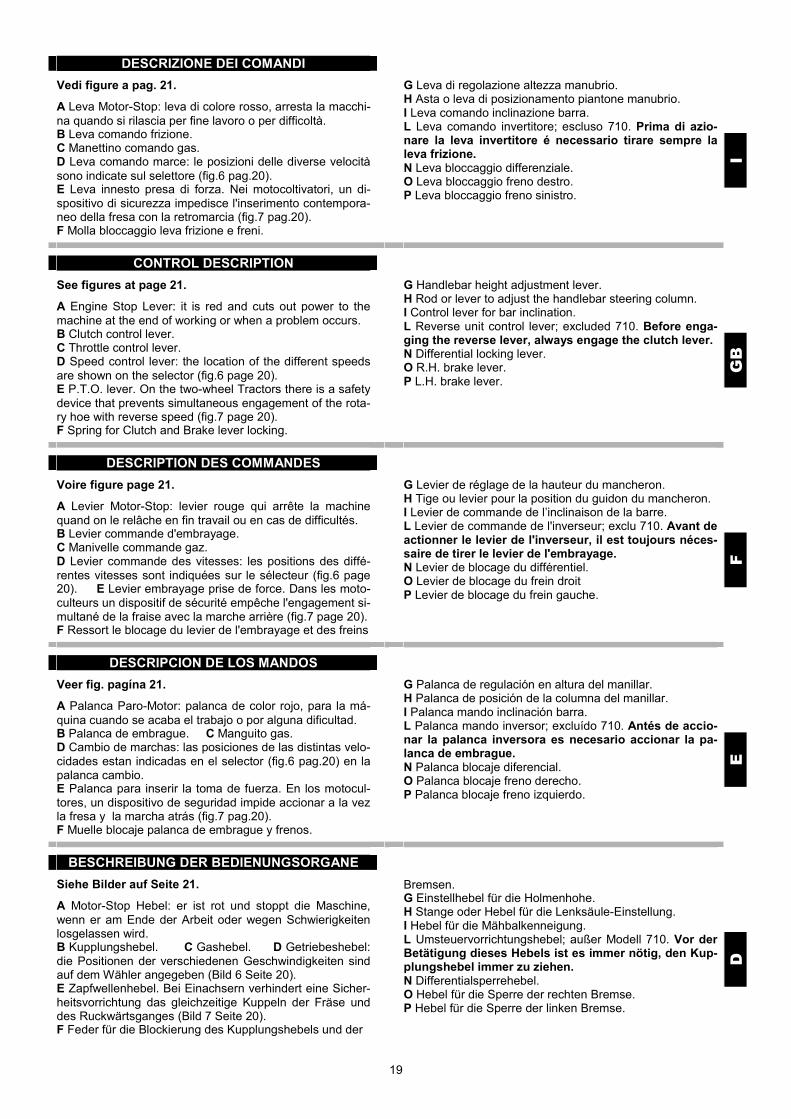
A Leva Motor-Stop: leva di colore rosso, arresta la macchi-na quando si rilascia per fine lavoro o per difficoltà. B Leva comando frizione. C Manettino comando gas. D Leva comando marce: le posizioni delle diverse velocità sono indicate sul selettore (fig.6 pag.20). E Leva innesto presa di forza. Nei motocoltivatori, un di-spositivo di sicurezza impedisce l'inserimento contempora-neo della fresa con la retromarcia (fig.7 pag.20). F Molla bloccaggio leva frizione e freni.
G Leva di regolazione altezza manubrio. H Asta o leva di posizionamento piantone manubrio. I Leva comando inclinazione barra. L Leva comando invertitore; escluso 710. Prima di azio-nare la leva invertitore é necessario tirare sempre la leva frizione. N Leva bloccaggio differenziale. O Leva bloccaggio freno destro. P Leva bloccaggio freno sinistro.
CONTROL DESCRIPTION
GB
See figures at page 21.
A Engine Stop Lever: it is red and cuts out power to the machine at the end of working or when a problem occurs. B Clutch control lever. C Throttle control lever. D Speed control lever: the location of the different speeds are shown on the selector (fig.6 page 20). E P.T.O. lever. On the two-wheel Tractors there is a safety device that prevents simultaneous engagement of the rota-ry hoe with reverse speed (fig.7 page 20). F Spring for Clutch and Brake lever locking.
G Handlebar height adjustment lever. H Rod or lever to adjust the handlebar steering column. I Control lever for bar inclination. L Reverse unit control lever; excluded 710. Before enga-ging the reverse lever, always engage the clutch lever. N Differential locking lever. O R.H. brake lever. P L.H. brake lever.
DESCRIPTION DES COMMANDES
F
Voire figure page 21.
A Levier Motor-Stop: levier rouge qui arrête la machine quand on le relâche en fin travail ou en cas de difficultés. B Levier commande d'embrayage. C Manivelle commande gaz. D Levier commande des vitesses: les positions des diffé-rentes vitesses sont indiquées sur le sélecteur (fig.6 page 20). E Levier embrayage prise de force. Dans les moto-culteurs un dispositif de sécurité empêche l'engagement si-multané de la fraise avec la marche arrière (fig.7 page 20). F Ressort le blocage du levier de l'embrayage et des freins
G Levier de réglage de la hauteur du mancheron. H Tige ou levier pour la position du guidon du mancheron. I Levier de commande de l’inclinaison de la barre. L Levier de commande de l'inverseur; exclu 710. Avant de actionner le levier de l'inverseur, il est toujours néces-saire de tirer le levier de l'embrayage. N Levier de blocage du différentiel. O Levier de blocage du frein droit P Levier de blocage du frein gauche.
DESCRIPCION DE LOS MANDOS
E
Veer fig. pagína 21.
A Palanca Paro-Motor: palanca de color rojo, para la má-quina cuando se acaba el trabajo o por alguna dificultad. B Palanca de embrague. C Manguito gas. D Cambio de marchas: las posiciones de las distintas velo-cidades estan indicadas en el selector (fig.6 pag.20) en la palanca cambio. E Palanca para inserir la toma de fuerza. En los motocul-tores, un dispositivo de seguridad impide accionar a la vez la fresa y la marcha atrás (fig.7 pag.20). F Muelle blocaje palanca de embrague y frenos.
G Palanca de regulación en altura del manillar. H Palanca de posición de la columna del manillar. I Palanca mando inclinación barra. L Palanca mando inversor; excluído 710. Antés de accio-nar la palanca inversora es necesario accionar la pa-lanca de embrague. N Palanca blocaje diferencial. O Palanca blocaje freno derecho. P Palanca blocaje freno izquierdo.
BESCHREIBUNG DER BEDIENUNGSORGANE
D
Siehe Bilder auf Seite 21.
A Motor-Stop Hebel: er ist rot und stoppt die Maschine, wenn er am Ende der Arbeit oder wegen Schwierigkeiten losgelassen wird. B Kupplungshebel. C Gashebel. D Getriebeshebel: die Positionen der verschiedenen Geschwindigkeiten sind auf dem Wähler angegeben (Bild 6 Seite 20). E Zapfwellenhebel. Bei Einachsern verhindert eine Sicher-heitsvorrichtung das gleichzeitige Kuppeln der Fräse und des Ruckwärtsganges (Bild 7 Seite 20). F Feder für die Blockierung des Kupplungshebels und der
Bremsen. G Einstellhebel für die Holmenhohe. H Stange oder Hebel für die Lenksäule-Einstellung. I Hebel für die Mähbalkenneigung. L Umsteuervorrichtungshebel; außer Modell 710. Vor der Betätigung dieses Hebels ist es immer nötig, den Kup-plungshebel immer zu ziehen. N Differentialsperrehebel. O Hebel für die Sperre der rechten Bremse. P Hebel für die Sperre der linken Bremse.

20

21

22
APPLICAZIONE ATTREZZI
I
Gli attrezzi si applicano direttamente alla flangiatura A (fig.12) oppure interponendo l’attacco rapido C (fig.13). E’ necessario che i dadi D (fig.13) che fissano l’attrezzo alla macchina siano ben serrati. Per applicare ai motocoltivatori la barra falciante, il tosa-erba, lo spazzaneve, ecc. è necessario ruotare il manubrio di 180°.
Prima di fare questo, vanno sganciate le aste di comando marce F e presa di forza G dai supporti H; tirare la leva di posizionamento piantone manubrio L e girare di 180° (fig.14 - 15). Reinserirla una volta scelta la posizione ideale del manu-brio. Girato il manubrio le aste vanno reinserite nei sup-porti. Con ruotato il manubrio, il motocoltivatore 710 avanzerà in retromarcia e retrocederà in 1a marcia.
IMPLEMENT ASSEMBLY
GB
Implements are mounted directly to the flange A (fig.12) or fitting between the attachment the quick hitch C (fig.13). It is necessary that nuts D (fig.13) which fasten the imple-ment to the machine are well tightened. To mount to the two-wheel tractors the cutter bar, the lawn-mower, the snow thrower, etc. it is necessary to turn the handlebar of 180°.
Before this, it is necessary to release the speed F and P.T.O. control rods G from supports H, pull the handlebar steering column position lever L and turn it 180° (fig.14-15). Insert it again after choosing the ideal position of the handlebar. After turning the handlebar, rods must be inserted again into the supports; when the handlebar is turned, the two-wheel tractor 710 will go forward in reverse speed and back in 1st speed.
MONTAGE OUTILS
F
Les outils sont montés directement à la bride A (fig.12) ou bien entreposant l’attache rapide C (fig.13). Les écrous D (fig.13) qui fixent l’outil à la machine doivent être bien serrés. Pour appliquer aux motoculteurs la barre de coupe, la ton-deuse, le chasse-neige, etc. il est nécessaire de tourner le mancheron de 180°.
Avant de faire celà, on doit décrocher des supports H les tiges de commande des marches F et prise de force G, tirer le levier pour la mise en position du guidon L et tourner de 180° (fig.14-15). Le réinsérer après avoir choisi la position idéale du man-cheron. Après avoir tourné le mancheron, les tiges doivent être réinsérées dans les supports. Avec le mancheron tourné, le motoculteur 710 avancera en marche arrière et reculera en 1ère marche.
APLICACION APEROS
E
Los aperos se aplican directamente a la flangia A (fig.12) o bien poniendo entre un enganche rápido C (fig.13). Es necesario que las tuercas D (fig.13) que fijan el apero a la máquina esten bien apretadas. Para acoplar al motocultor la barra de siega, el corta-césped, el quitanieves, etc. es necesario girar el manillar 180°.
Antes de hacer esto, cuando se desengancha el asta del mando marchas F y la toma de fuerza G del soporte H, tirar de la palanca de posición de la columna del manillar L y girar de 180° (fig.14-15). Reinserirla una vez encontrada la posición ideal del ma-nillar. Girando el manillar las astas se meterán en los soportes. Con el manillar girado et motocultor 710 avanza con la marcha atrás y retrocede con la primera marcha.
MONTAGE DER ARBEITSGERATE
D
Die Arbeitsgeräte werden mittels Flansch A (Bild 12) oder mittels Schnellanschluß C (Bild 13) zwischen Arbeitsgerät und Maschine direkt montiert. Die Muttern D (Bild 13) welche das Arbeitsgerät an der Maschine befestigen, müssen gut angezogen werden. Um an den Einachsern den Mahbalken, Schneeschleuder, Rasenmaher, etc. ist es notig, den Holmen um 180° zu drehen.
Vor dieser Arbeit muß man Geschwindigkeits F und Zapf-wellenstange G von den Lagern H auskuppeln, Hebel für die Holmen-Einstellung L ziehen den 180° (fig.14-15). Nachdem Sie die gewunschte Holmenstellung gewählt haben, schalten Sie den Hebel wieder. Nach Drehen des Holmens müssen die Stangen wieder in ihre Lager geschaltet werden. Mit gedrehtem Holmen wird der Einachser 710 in Rückwärtsgang vorwärtsfahren und in 1.Gang rückwärtsfahren.

23

24
APPLICAZIONE ATTREZZI PRESA DI POTENZA
I
Per i motocoltivatori 718-720-722-730-732 che sono mac-chine dotate di invertitore, ruotato il manubrio di 180° si hanno a disposizione 2 marce avanti che rilasciando la leva rossa M (fig.16) posta sul manubrio diventano retro-marce.
É a 3 denti con innesto frontale. La rotazione è destra, indi-pendente dal cambio, vincolata alla velocità del motore (990 giri/1’ a 3600 giri/1’ del motore). Per lo schema e le dimensioni della flangiatura vedi fig. 17/1.
IMPLEMENT ASSEMBLY P.T.O.
GB
As the two-wheel tractors 718-720-722-730-732 are equip-ped with an automatic reverser, if you turn the handlebar of 180° you get two forward speeds, that, pulling red lever M (fig.16) on the handlebar, become reverse speed.
It is a front locking 3-teeth implement. It rotates right, inde-pendently from the gear, and depending on the motor speed (990 rev/1’ at 3600 rev/1’ of the motor). For the scheme and the flange dimension, please refer to figure 17/1.
MONTAGE OUTILS PRISE DE PUISSANCE
F
Pour les motoculteurs 718-720-722-730-732 qui sont équi-pés de l’inverseur automatique, en tournant le mancheron de 180° on dispose de 2 marches avant qui, en tirant le le-vier rouge M (fig.16) placé sur le mancheron, deviennent marches arrières.
A 3 dents avec insertion frontale rotation à droite, indépen-dente du chargement de vitesse, est liée à la vitesse du mo-teur (990 tours/1’ à 3600 tours/1’ du moteur). Schéma et dimensions des brides (fig.17/1).
APLICACION APEROS TOMA DE FUERZA
E
Los motocultores 718-720-722-730-732 que son máquinas dotadas de invertidor automático, girando el manillar 180° se dispone de 2 marchas adelante que tirando de la palanca roja M (fig.16) del manillar se convierte en marcha atrás.
Es a tres dientes con conexión frontal. La rotación es hacia la derecha, indipendiente del cambio, vinculada a la veloci-dad del motor (990 giros/1’ a 3600 giros/1’ del motor). Por el esquema y las dimensiones de la flangia ver fig. 17/1.
MONTAGE DER ARBEITSGERATE ZAPFWELLE
D
Bei den Einachser 718-720-722-730-732, welche die auto-matische Umsteuervorrichtung haben, erhalten Sie durch Drehen des Holmen 2 Vorwärtsgänge, welche zu Rüch-wärtsgangen werden, wenn Sie den roten Hebel M (Bild 16) auf dem Holmen ziehen.
Zähnen vordere Einkupplung Zapfwelle. Das Drehen ist nach recht, unabhängig vom Getriebe, je nach der Gesch-windigkeit (990 Dreh./1’ bei 3600 Dreh./1’ des Motors). Siehe Bild 17/1 für das Schema und die Abmessungen der Flansche.

25

26
CONTROLLI DA ESEGUIRE PRIMA DI AVVIARE LA MACCHINA
I
Seguendo le istruzioni contenute nel libretto uso e manu-tenzione del motore, controllare il livello dell’olio. E’ bene lavorare con il livello dell’olio al massimo, specialmente quando si lavora su pendenze, per avere così una sicura lubrificazione. In caso di rabboccamento dell’olio usare qualità e densità indicate nel libretto stesso.
Controllare il livello dell’olio nella scatola cambio, sfilando il tappo A (fig.13) e verificare che il livello sia compreso fra le due tacche B e C.
In caso di rabbocco aggiungere olio AGIP ROTRA MP SAE 80W / 90 (rif. US.A.MIL – L – 2105C) (per elevate pressioni).
Riempire il serbatoio di carburante, non fare mai riforni-mento con il motore in moto, utilizzate un imbuto con filtro a rete in modo da trattenere le eventuali impurità.
Completate queste operazioni la macchina è pronta per essere avviata.
CHECKS BEFORE STARTING THE MACHINE
GB
Check oil level, following the instructions in the engine ope-rating manual. To ensure correct lubrication, especially when working on slopes, the oil level should be at maxi-mum.
Should the oil spill off, use the quality and density as pre-scribed in the same operating manual.
Check oil level in the gearbox through oil plug A (fig.13), verify that the level is between the two grooves B and C.
If necessary, add oil AGIP ROTRA MP SAE 80W / 90 (rif. US.A.MIL. – L – 2105C) (for high pressures).
Fill tank with fuel using a funnel with a mesh filter to eliminate impurities. Never fill the tank whilst engine is run-ning.
After having performed these operations the machine is ready to be started.
CONTROLES A EFFECTUER AVANT DE DEMARRER LA MACHINE
F
En suivant les instructions données dans le manuel du mo-teur, contrôler le niveau de l’huile. Travailler avec le niveau de l’huile au maximum, particulièrement quand on travaille sur des pentes, pour avoir une lubrification sûre. En cas de remplissage, utiliser une huile en quantité et de densité conformes a celle indiquée dans le manuel.
Contrôler le niveau de l’huile dans la boîte de vitesses en ôtant le bouchon A (fig.13) et en vérifiant que le niveau de l’huile soit compris entre les deux marques B et C.
Si necessaire, ajouter de l’huile AGIP ROTRA MP SAE 80W / 90 (rif. US.A.MIL. – L – 2105C) (pour pressions éle-vées).
Remplir le réservoir de carburant, mais jamais avec le moteur en marche.
Utilisez un entonnoir avec filtre en tamis de façon à retenir d’éventuelles impuretés. Ces opérations complétées, la machine est prête pour être démarrée.
CONTROLES A EFECTUAR ANTES DE PONEREN MARCHA LA MAQUINA
E
Siguiendo las instrucciones contenidas en el librito de uso y manutención del motor, controlar el nivel de aceite. Es aconsejable trabajar con el nivel de aceite al máximo, especialmente cuando se trabaja en pendientes, para tener asi una segura lubrificación. En caso de añadir acei-te, usar la calidad y densidad indicada en el mismo librito.
Controlar el nivel de aceite de la caja de cambio, retirando el tapón A (fig.13) y verificar si el nivel llega entre las dos marcas B y C.
En caso de tener que añadir aceite, usar AGIP ROTRA MP SAE 80W / 90 (rif. US.A.MIL. – L – 2105C) (para elevadas presiones).
Rellenar el depósito del carburante, no lo haga nunca con el motor funcionando.
Utilice un embudo con filtro de reja para retener cualquier impureza. Hecha esta operación, la máquina estará a punto para su funcionamiento.
VOR DEN INBETRIEBNAHME VORZUNEHMENDE KONTROLLEN
D
Ölstand im Motor kontrollieren (siehe die entsprechenden Betriebsanleitung). Das Öl sollte sich am höchsten Stand besonders am Hang befinden, um eine sichere Schmie-rung zu gewährleisten.
Bei Bedarf mit Öl der vom Hersteller angegebenen Qualität und Viskosität auffüllen.
Den Ölstand im Getriebekasten nach Entfernen der Ver-schraubung A (Bild 13) prüfen. Der Ölstand muss zwischen den beiden Markierungen B und C liegen.
Bei Bedarf mit Öl AGIP ROTRA MP SAE 80W / 90 (rif. US.A.MIL. – L – 2105C) auffüllen (Hochdruck).
Den Tank mit Kraftstoff auffüllen, niemals mit laufendem Motor füllen.
Das Benzin muss immer durch einen Trichter mit Netzfilter eingefüllt werden, damit keine Fremdkörper in das Kraft-stoffsystem gelangen können.
Die Maschine ist auf diese Weise arbeitsbereit.

27
AVVIAMENTO DELLA MACCHINA ED INIZIO LAVORO
I
Prima di avviare il motore assicurarsi che il cambio sia in posizione di folle e che la presa di forza non sia innestata.
1) Abbassare la leva Motor Stop A e tirare la leva frizione B, bloccarle con il fermo C (fig.19-20). Portare il manettino comando acceleratore a metà corsa.
2) Predisporre il motore per l’accensione, leggendo sul libretto uso e manutenzione del motore, le necessarie ope-razioni.
TO START THE MACHINE
GB
Ensure that gear lever and PTO lever are disengaged.
1) Lower the Stop-lever A, engage the clutch lever B, and lock them with stopper C (fig.19-20). Set the throttle at half-way position.
2) Set engine for starting as described in the engine ma-nual.
DEMARRAGE DE LA MACHINE ET COMMENCEMENT DU TRAVAIL
F
Avant de démarrer le moteur, s’assurer que le changement de vitesses soit au point mort et que la prise de force ne soit pas engagée.
1) Baisser le levier du Motor-stop A et tirer le levier embra-yage B, les bloquer par le ressort C (fig.19-20). Porter le levier de commande de l’accélérateur à mi-course.
2) Préparer le moteur pour l’allumage selon les instructions données dans le manuel du moteur.
ARRANQUE DE LA MAQUINA Y INICIO DEL TRABAJO
E
Antes de arrancar el motor asegurarse de que el cambio está en posición neutra y que la toma de fuerza no está conectada.
1) Bajar la palanca de Paro motor A y apretar la palanca de embrague B, bloquearlas por el muelle C (fig.19-20). Poner el manguito del mando acelerador e la mitad.
2) Predisponer el motor para el arranque, leyendo el librito de uso y mantenimiento del motor, de las operaciones necesarias.
INBETRIEBENAHME DER MASCHINE UND BEGINN DER ARBEIT
D
Vor dem Motoranlassen sich vergewissern, daß das Um-kehrgetrieb im Leerlauf ist und die Zapfwelle nicht einge-schaltet ist.
1) Den Motor-Stop Hebel A auf die niedrigere Position stellen, den Kupplungshebel B ziehen, mit der Feder C (Bild 19-20) befestigen. Den Gashandhebel zur Hälfte ein-stellen.
2) Den Motor für die Zündung aufgrund der entsprechen-den Betriebsanleitung vorbereiten.
18

28
I
3) Afferrare la maniglia dell’avviamento, tirarla dolcemente fino a che si aggancia l’arpionismo, quindi appoggiare il piede (fig.21) e dare un energico strattone. La maniglia va afferrata con UNA SOLA MANO, per evitare contraccol-pi del motore che possono ferire l’operatore. Una volta che il motore è avviato, lasciarlo girare a vuoto qualche minuto per dar tempo all’olio di raggiungere tutti gli organi in movimento. Impugnare il manubrio e serrare la leva frizione per sganciare la molla di ritegno; fare atten-zione a non rilasciare la leva Motor-Stop A (fig.19-20) perchè la macchina si fermerà all’istante.
Innestare la marcia desiderata, portando l’asta comando cambio in corrispondenza della marcia prescelta. Nel caso che la marcia non si innestasse subito dare dei piccoli colpi di frizione. Una volta innestata la marcia rila-sciare la frizione lentamente, fino a che la macchina si sarà messa in movimento. Per mettere in movimento l’attrezzo, azionare la leva della frizione, inserire la presa di forza con l’asta di comando posta sul piantone manubrio, dare dei piccoli colpi di frizio-ne nel caso in cui non ci sia innesto immediato del coman-do.
GB
3) Slowly pull the starting handle until the hooking system is engaged, then give a strong pull placing the foot (fig.21). The rope handle must always be grasped with ONE HAND ONLY, to prevent the engine “kicking back”. When the engine has started, allow it to run idle for some minutes to allow oil to lubricate all moving parts. Grip the clutch lever on the handlebars to allow the locking stop spring to release, making sure not to fully release the Stop-lever A (fig.19-20) which will stop the engine running.
Engage and locate the speed control rod to the desired speed position. If the gear does not engage immediately release the clutch lever slightly and “feel-in”. When the gear is engaged, release the clutch lever slowly and fully until the machine starts. To engage drive to the implement, engage the clutch lever and locate the control rod in its forward position. If enga-gement is not immediate, release the clutch lever slightly and “feel-in”.
F
3) Prendre la poignée du lanceur, la tirer doucement jusqu’à l’accrocher à l’encliquetage, puis appuyer le pied (fig.21) et tirer énergiquement. La poignée doit être tenue d’UNE SEUL MAIN pour éviter d’éventuels contrecoups du moteur qui peuvent blesser l’opérateur. Une fois le moteur allumé, le laisser tourner à vide pendant quelques minutes pour permettre à l’huile d’atteindre tous les organes en mouvement. Prendre le mancheron et serrer le levier d’embrayage pour décro-cher le ressort d’arrêt: faire attention à ne pas relâcher le levier du Motor-stop A (fig.19-20) car la machine s’ar-rêtera à l’instant.
Enclencher la marche souhaitée en amenant la tige de commande de la boîte de vitesses en correspondance de la vitesse désirée. Au cas où la vitesse n’entrerai pas tout de suite, donner des petits coups d’embrayage. Une fois mise en marche, embrayer lentement jusqu’à ce que la machine soit entrée en mouvement. Pour mettre en mouvement l’outil, tirer le levier d’em-brayage, actionner la prise de force par la tige de com-mande située sur le guidon du mancheron, donner de pe-tits coups d’embrayage au cas où la commande n’embra-yerait pas.
E
3) Coger la manecilla de arranque, tirar de ella suave-mente hasta que se enganche al gancho, después apoyar los pies (fig.21) y dar un fuerte tirón. El puño debe cogerse con UNA SOLA MANO, para evitar contragolpes del motor que podrían herir al ope-rador. Una vez el motor está en marcha, dejarlo rodar durante unos minutos para dar tiempo a que el aceite llegue a todos los órganos de movimiento. Empuñar el manillar y apretar la palanca del embrague para engan-char el muelle del freno; preste atención en no dejar la palanca de Paro-motor A (fig.19-20) porque la máquina se parará al instante.
Escoja la marcha deseada, llevando la palanca de cambio a la marcha correspondiente. En el caso que la marcha no entre, dé un pequeño golpe al embrague. Una vez puesta en marcha deje el embrague lentamente, hasta que la máquina se ponga en movimien-to. Para poner en movimiento el apero, accionar la palanca de embrague, inserir la toma de fuerza con la palanca del mando situado en la columna del manillar, dar un pequeño golpe al embrague en el caso de que no se accione solo con el mando.
D
3) Den Anlassergriff sanft ziehen, bis die Rastvorrichtung einrastet. Dann den Fuß wie im (Bild 21) gezeigt aufsetzen und den Motor mit einem Ruck anwerfen. In beiden Fallen darf der Anlassergriff immer NUR MIT EINER HAND betätigt werden, um Verletzungen beim Ruckschlagen des Motors zu vermeiden. Seilrolle anlas-sen. Wenn der Motor anspringt, ihn einige Minuten leer-laufen lassen, damit das Schmieröl zu den beweglichen Maschinenteilen gelangen kann. Den Holmen ergreifen und den Kupplungshebel anziehen, um die Haltefeder zu lösen: Der Motor-Stop Hebel A (Bilder 19-20) muß nicht losgelassen werden, sonst wird der Motor sofort ab-stellen.
Zum Einlegen des gewünschten Ganges die Gangschalt-stange auf den vorgewählten Gang einstellen. Wenn der Gang nicht sofort einrastet, durch kurzes Betätigen des Kupplungshebels nachhelfen. Sobald der gewünschte Gang eingerückt ist, Kupplungshebel langsam loslassen, bis sich die Maschine Bewegung setzt. Um das Arbeits-gerät in Bewegung zu setzen, den Kupplungshebel betä-tigen, die Zapfwelle durch die Betätigungsstange am Hol-men einschalten und durch kurzes Betätigen des Kup-plungshebels nachhelfen, falls es keine sofortige Bewe-gung gibt.

29
I
Per i motocoltivatori un dispositivo di sicurezza im-pedisce l’innesto contemporaneo della retromarcia e della fresa; questo infatti potrebbe essere molto peri-coloso. Per innestare la retromarcia bisogna sempre disinnestare la presa di forza. Accelerare quindi il motore e rilasciare lentamente la frizione, iniziando così a lavorare. Terminato il lavoro, per arrestare il motore, decelerare, disinnestare la presa di forza e portare il cambio in posizione di folle, quindi rila-sciare la leva Motor-Stop A (fig.19-20).
GB
Please note that on two-wheel tractors it is impossible to engage reverse speed and the rotary hoe simulta-neously moving to a safety device. The P.T.O. must be disengaged before locating reverse gear. Accelerate engine and release clutch lever slowly and fully, to begin work. To stop engine and machine: decelerate, disengage the P.T.O. and speed control rods to neutral position and fully release the Stop-lever A (fig.19-20).
F
Pour les motoculteurs un dispositif de sécurité em-pêche l’embrayage simultané de la marche arrière et de la fraise: cela pourrait en effet être très dangereux. Pour actionner la marche arrière on doit toujours dé-brayer la prise de force. Accélérer le moteur et relâcher lentement l’embrayage pour commencer le travail. Le travail terminé, pour arrêter le moteur décélérer, débrayer la prise de force et porter le changement de vitesses au point mort. Relâcher le levier du Motor-stop A (fig.19-20).
E
Para los motocultores, existe un dispositivo de segu-ridad que impide inserir a la vez la marcha atrás y la fresa; lo cual podria resultar muy peligroso. Para poner la marcha atrás es necesario desconectar la toma de fuerza. Acabado el trabajo, para parar el motor, desacelerar, desconectar la toma de fuerza y llevar el cambio a po-sición neutra, después soltar la palanca de Paro-motor A (fig.19-20).
D
Bei den Einachsern verhindert eine Sicherheitsvorrich-tung das gleichzeitige Kuppeln des Ruckwärtsganges und der Fräse, weil das sehr gefahrlich sein könnte. Zum Einschalten des Ruckwärtsganges muß die Zapf-welle ausgekuppelt werden. Gas geben und die Kup-plung langsam loslassen. Nun kann mit der Arbeit be-gonnen werden.
Zum Abstellen des Motors nach beendigter Arbeit die Geschwindigkeit zurucknehmen, die Zapfwelle auskup-peln, das Umkehrgetriebe im Leerlauf bringen und den Motor-Stop Hebel A (Bilder 19-20) loslassen.

30
AVVIAMENTO ELETTRICO (a richiesta)
I
ATTENZIONE: l’elettrolito della batteria è costituito da aci-do solforico diluito e può causare bruciature gravi. Evitate in modo assoluto contatti con la pelle, gli occhi, il vestiario. Non avvicinate scintille, fiamme o sigarette accese. Venti-late durante la carica o l’impiego in locali chiusi. La batteria da installare è a 12V 14/16Ah (dimensioni max. mm 160x90x161; riferimento FIAMM 6M4P). Per i modelli con motore diesel installare il tipo a 12V 33/ 35Ah (dimensioni mm 232x130x167; riferimento SAEM 6LD5/P).
Predisporre il motore per l’avviamento seguendo le istru-zioni contenute nel libretto del motore stesso, abbassare la leva Motor-Stop, tirare la leva frizione ed agganciare con la molla (fig.19-20). Inserire la chiave di avviamento e girarla verso destra. Per spegnere il motore agire sulla leva Motor-Stop e togliere la chiave. Manutenzione: controllare periodicamente il livello del li-quido nella batteria.
ELECTRIC STARTER (for request)
GB
ATTENTION: battery electrolyte consists of diluted sul-phuric acid which can cause bad turns. Avoid contact with skin, eyes and clothing. Do not smoke or bring sparks or flames near to it. Always fill in a well ventilated environ-ment. The battery to be installed is a 12V 14/16Ah battery (size max mm 160x90x161; ref. FIAMM 6M4P). As concerns models with diesel motor install the 12V 33/35Ah type (size mm 232x130x167; ref. SAEM 6LD5/P).
Prepare engine for starting as per the instructions in the engine manual, depress the stop-lever, engage clutch lever and secure with the spring clip (fig.19-20). Insert key and turn to the right. To stop the engine release the stop-lever and extract key. Maintenance: check the liquid level in the battery perio-dically.
DEMARRAGE ELECTRIQUE (si demandé)
F
ATTENTION: le liquide électrolytique de la batterie est constitué d’acide sulfurique délayé et peut provoquer des brûlures graves. Absolument éviter le contact avec le peau, les yeux, les vêtements. Ne pas approcher des étin-celles, d’une flamme ou des cigarettes allumées. Ventiler pendant le chargement ou l’emploi dans des endroits clos. La batterie à installer a un voltage de 12V 14/16Ah (dimensions max mm 160x90x161; réf. FIAMM 6M4P). Pour les modèles à moteur diesel, installer le type à 12V 33/35Ah (dimensions mm 232x130x167; réf SAEM 6LD5/P).
Préparer le moteur pour le démarrage selon les instruc-tions contenues dans le manuel du moteur, baisser le levier Motor-Stop, tirer le levier d’embrayage et l’accrocher avec le ressort (fig.19-20). Introduire la clé de démarrage et la tourner vers la droite. Pour éteindre le moteur, agir sur le levier Motor-Stop et ôter la clé. Entretien: contrôler périodiquement le niveau du liquide dans la batterie.
ARRANQUE ELECTRICO (à solicitud)
E
ATENCION: el electrolito de la batería está constituido de ácido sulfúrico diluido y puede causar quemaduras graves. Evitar totalmente el contacto con la piel, los ojos y la ropa. No acerque chispas, inflamables o cigarrillos encendidos. Haga la operación en sitios ventilados. La batería que debe ser instalada es à 12V 14/16Ah (dimensiones max mm 160x90x161; rif: FIAMM 6M4P). Para los modelos con motor diesel, instalar el modelo à 12V 33/35Ah (dimensiones mm 232x130x167; rif: SAEM 6LD5/P).
Predisponga el motor para el arranque siguiendo las instrucciones contenidas en el librito del mismo motor; bajar la palanca Paro-motor, tirar de la palanca de embra-gue y engancharla al muelle (fig.19-20). Ponga la llave de arranque y girela hacia la derecha. Para parar el motor, accionar sobre la palanca de Paro-motor y girar la llave. Manutencion: controlar periódicamente el nivel del liquido de la batería.
ELEKTROSTARTER (Anforderung)
D
ACHTUNG: Sie ist durch verdünnte Schwefelsäure zu-sammengesetzt und kann schwere Verbrennungen verur-sachen. Vermeiden Sie jede Berührung mit den Augen, der Haut und den Kleidern. Sich niemals mit angebrannten Zigaretten, Funken oder Flammen nähern. Während der Ladung in geschlossenen Räumen gut lüften.
Die Batterie zum Installieren ist 12V 14/16Ah (Abmessung max mm 160x90x161; Bezug FIAMM 6M4P). Installieren Sie den Typ 12V 33/35Ah für Modellen mit Dieselmotor (Abmessung mm 232x130x167; Bezug SAEM 6LD5/P).
Den Motor den entsprechenden Anweisungen zum Anlas-sen vorbereiten. Den Motor-Stop Hebel auf niedrige Posi-tion stellen den Kupplungshebel ziehen und an Feder an-haken (Bilder 19-20). Anlasserschlüssel einstecken und nach rechts drehen. Um den Motor abzustellen, den Motor-Stop Hebel betäti-gen und Schlüssel herausziehen. Wartung: Den Flüssigkeitsstand in der Batterie regelmäs-sig kontrollieren.

31
LUBRIFICAZIONE E MANUTENZIONE
I
Una adeguata manutenzione ed una corretta lubrificazione contribuiscono a mantenere la macchina sempre in per-fetta efficienza. La macchina viene fornita completa di lu-brificanti; controllare comunque i livelli dell’olio prima di iniziare il lavoro. Controllare che tutte le viti ed i dadi siano sempre ben serrati, in modo particolare i dadi D (fig.13) che fissano gli attrezzi alla macchina, i dadi che fissano le ruote e quelli che fissano il motore. Oliare le bussole di scorrimento dell’asta bloccaggio piantone manubrio.
FRIZIONE: in origine, la posizione della leva A (fig.24) risulta normale. Con l’usura della frizione la stessa leva si può aprire molto risultando scomoda da azionare, questo significa che occorre registrare il cavo riportando la leva A in posizione originale agendo sul registro B e il controdado C. MOTORE: per gli intervalli di manutenzione seguire le norme contenute nel libretto uso e manutenzione del moto-re. Di massima è opportuno controllare il livello dell’olio ogni 4 ore di lavoro e sostituirlo ogni 50 ore. Impiegare sempre olio di buona qualità come indicato sul libretto uso e manutenzione del motore.
LUBRICATION AND MAINTENANCE
GB
A proper maintenance and lubrication will help keep the machine in a perfect working condition. The machine is delivered full of lubricants, however check oil levels before starting work. Check that all screws and nuts are well tightened; particularly nuts D (fig.13) that fix the attachments to the machine, the nuts that fix wheels and ones fixing the engine. Lubricate the sliding bushes of the steering column stop rod.
CLUTCH: Originally, the position of A lever (fig.24) is normal. As clutch wears out the same lever could have a wider opening, being so uneasy to use, this means that it is necessary to adjust the cable, setting lever A on its original position acting on adjustment device B and on counter-nut C. ENGINE: For the maintenance intervals follow the instructions given in the operating manual of engine. You should check the oil level every 4 hours of work and replace it every 50 hours of work. Always use good quality oil as indicated on the motor instruction book.
LUBRIFICATION ET ENTRETIEN
F
Un entretien efficace et une lubrification correcte contri-buent à garder toujours la machine en état de parfait ren-dement. La machine est livrée complète avec le lubrifiant: contrôler toutefois le niveau de l’huile avant de commencer le travail. Contrôler que toutes les vis et les écrous soient toujours bien serrés, en particulier les écrous D (fig.13) qui fixent les outils à la machine, les écrous qui fixent les roues et ceux qui fixent le moteur. Huiler les douilles de la tige de blocage du tube de direction du mancheron.
EMBRAYAGE: En origine, la position du levier A (fig.24) résulte normale. Suite à l’usure de la friction, la même levier peut s’ouvrir beaucoup, en devenant incommode à actionner: cela signifié qu’il faut enregistrer le câble, en ramenant le levier A à la position originale. Agir donc sur le registre B et le contre-ecrou C.
MOTEUR: Pour les intervalles de lubrification, suivre les données contenues dans ce livret du moteur. En principe il est utile de contrôler le niveau de l’huile toutes les 4 heures de travail et de changer toutes les 50 heures. Em-ployer toujours de l’huile pour moteur de bonne qualité.
LUBRICACION Y MANTENIMIENTO
E
Una correcta manutención y una correcta lubrificación contribuyen a mantener la máquina siempre en perfecto estado. La máquina viene proveída completamente de lubricante; controlar el nivel de aceite antes de iniciar el trabajo. Controlar que todos los tornillos y las tuercas estén siem-pre bien apretados, sobre todo los tornillos D (fig.13) que fijan los aperos a la máquina, los tornillos que fijan las ruedas y los que fijan el motor. Untar las agujas de desli-zamiento del asta de blocaje de la columna del manillar.
EMBRAGUE: En origen, la posición de la palanca A (fig.24) es normal. Por el desgaste del enchufe, la palanca misma puede abrirse mucho, acabando à ser dificil à accionar. Esto significa que el cable tiene que ser registrado nuevamente, llevando la palanca à la posición original, abrando sobre el registro B y la contratuerca C.
MOTOR: Para los intervalos de manutención seguir las normas contenidas en el librito de uso y manutención del motor. Es oportuno controlar el nivel del aceite cada 4 horas de trabajo y sustituirlo cada 50 horas. Reponer siempre con aceite de buena calidad.
SCHMIERUNG UND WARTUNG
D
Eine vorschriftsmässige Wartung und Schmierung sind für die einwandfreie Funktion der Maschine von ausschlagge-bender Bedeutung. Die Maschine wird mit Schmiermittel-füllung ausgeliefert. Dennoch muss der Ölstand vor der Inbetriebnahme kontrolliert werden. Prüfen, dass alle Schrauben und Muttern, besonders Mut-tern D (Bild 13), welche das Arbeitsgerät mit der Maschine befestigen, und die Muttern, mit welchen die Räder und der Motor befestigt sind, fest angezogen sind. Die Gleit-buchsen des Lenkholm-Feststellhebels.
KUPPLUNG: Ursprunglich ist die Stellung des Hebels A (Bild 24) normal. Im Laufe der Zeit mit dem Verbrauch der Kupplung kann der Hebel mehr öffnen, und deswegen wird sein Gebrauch schwierig; das bedeutet, dass es notwendig ist, der Kabel einstellen beim Stellen des Hebel A in der ursprunglichen Stellung durch den Regler B und die Ge-genmutter C.
MOTOR: Die Schmierung muß in den im Motorhandbuch vorgeschriebenen Zeitabständen vorgenommen werden. Der Ölstand soll grundsätzlich alle 4 Arbeitsstunden kon-trolliert werden. Der Ölwechsel ist nach jeweils 50 Arbeits-stunden geprüft werden. Immer ein gutes Motorenöl Ölsor-te.

32
I
Per il filtro aria a bagno d’olio, se l’ambiente di lavoro è molto polveroso, lavare la matassa filtrante e ripristinare il livello dell’olio ogni 8 ore. Usare lo stesso olio del motore. Per i motori che hanno il filtro aria con elemento filtrante di carta, occorre pulirlo con aria oppure sostituirlo se è molto intasato. SCATOLA CAMBIO: Controllare il livello dell’olio ogni 50 ore di lavoro togliendo il tappo A e verificando che, a mac-china orizzontale, l’olio arrivi tra le due tacche B/C (fig.23). Se occorre, aggiungere olio per cambi AGIP ROTRA MP SAE 80W/90 (rif. US.A.MIL – L – 2105C).
GB
For the oil bath air filter, if you work in dusty conditions, wash the filtering hank and add oil every 8 hours. Use the same oil as for engine. For the engines having the air filter with the paper filter, clean this element with air or replace if it is very obstructed. GEARBOX: Check oil level every 50 hours of work re-moving plug A and check that, with horizontal machine, oil reaches the two notches B/C (fig.23). If necessary, add gearbox oil AGIP ROTRA MP SAE 80W/90 (rif. US.A.MIL – L – 2105C).
F
Pour le filtre à air à bain d’huile, si l’endroit est très pous-siéreux, laver l’écheveau filtrant et ramener l’huile au ni-veau requis toutes les 8 heures. Utiliser la même huile que pour le moteur. Pour les moteurs qui ont le filtre à air avec élément filtrant en papier, le nettoyer à l’air comprimé ou le remplacer s’il est très obstrué. BOITE DE VITESSES: Contrôler le niveau de l’huile toutes les 50 heures de travail en ôtant le bouchon A et en con-trôlant que,avec la machine horizontale, l’huile atteigne les deux marques B/C (fig.23). Si nécessaire, ajouter de l’huile pour boîtes de vitesse AGIP ROTRA MP SAE 80W/90 (rif. US.A.MIL – L – 2105C).
E
Para el filtro de aire en baño de aceite, si el ambiente de trabajo es polvoriento, lavar la reja del filtro y restablecer el nivel del aceite cada 8 horas. Usar el mismo aceite del motor. Para los motores que tengan el filtro de aire con elemento filtrante de papel, debera pulirlo con aire o bien sustituirlo si está muy sucio. CAJA DE CAMBIO: Controlar el nivel del aceite cada 50 horas de trabajo, quitando el tapón A y controlando que, con la máquina horizontal el aceite llegue entre las dos señales, B/C (fig.23). Se deberá utilizar para la caja de cambio aceite AGIP ROTRA MP SAE 80W/90 (rif. US.A. MIL – L – 2105C).
D
Lüftfilter im Ölbad: Im staubiger Umgebung den filtrieren-den Einsatz waschen und den Ölstand alle 8 Stunden kon-trollieren. Mit der gleichen, für die Motorschmierung be-nutzten Ölsorte auffüllen. Der Luftfilter mit filtrierendem Pa-pierelement muss mit Luftdruck gereinigt werden. Sollte es sehr verstopft sein, muss er ersetzt werden. GETRIEBEKASTEN: Den Ölstand in Zeitasbtänden von jeweils 50 Betriebsstunden nach Entfernen der Füllschrau-be A kontrollieren. Bei flachsstehender Maschine muss das Öl zu den beiden Rädern B/C (Bild 23) reichen. Beim Bedarf mit Getriebeöl AGIP ROTRA MP SAE 80W/90 (rif. US.A.MIL – L – 2105C) auffüllen.
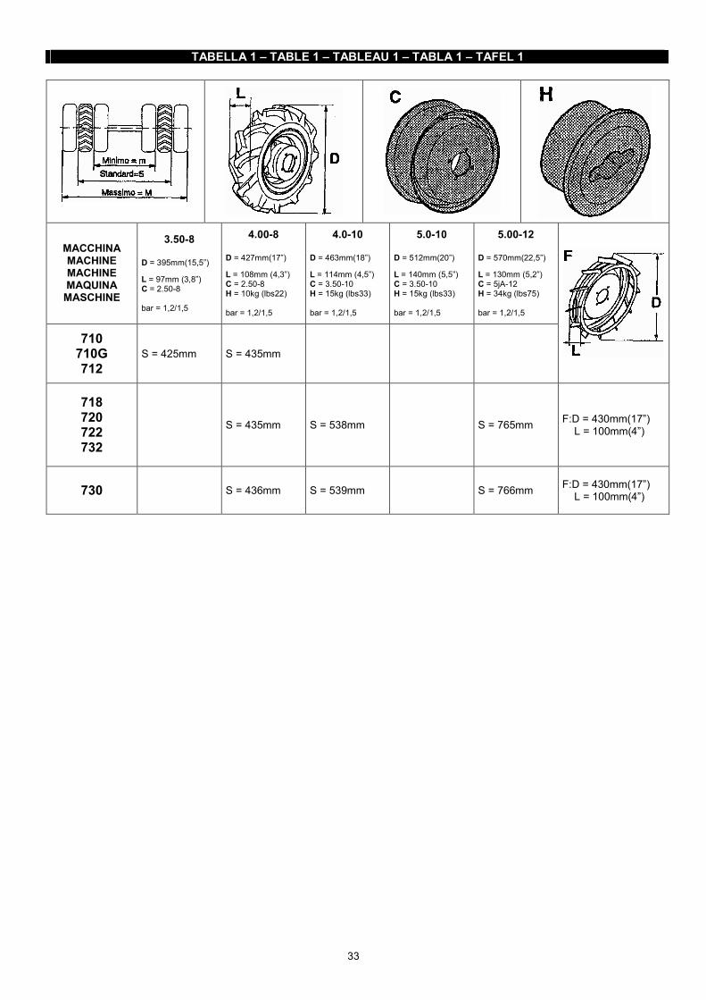
33
TABELLA 1 – TABLE 1 – TABLEAU 1 – TABLA 1 – TAFEL 1
MACCHINA MACHINE MACHINE MAQUINA
MASCHINE
3.50-8 D = 395mm(15,5”)
L = 97mm (3,8”) C = 2.50-8 bar = 1,2/1,5
4.00-8 D = 427mm(17”)
L = 108mm (4,3”) C = 2.50-8 H = 10kg (lbs22) bar = 1,2/1,5
4.0-10 D = 463mm(18”)
L = 114mm (4,5”) C = 3.50-10 H = 15kg (lbs33) bar = 1,2/1,5
5.0-10 D = 512mm(20”)
L = 140mm (5,5”) C = 3.50-10 H = 15kg (lbs33) bar = 1,2/1,5
5.00-12 D = 570mm(22,5”)
L = 130mm (5,2”) C = 5jA-12 H = 34kg (lbs75) bar = 1,2/1,5
710 710G 712
S = 425mm S = 435mm
718 720 722 732
S = 435mm S = 538mm S = 765mm F:D = 430mm(17”) L = 100mm(4”)
730 S = 436mm S = 539mm S = 766mm F:D = 430mm(17”) L = 100mm(4”)

34
TABELLA 2 – TABLE 2 – TABLEAU 2 – TABLA 2 – TAFEL 2
MOTORE - ENGINE MOTEUR - MOTOR cm³ kW
giri / 1’ - r.p.m. - tour/min. -
U/min.
Benzina - Gasoline Essence - Gasolina
- Benzin DIESEL
Acme ACT 340 338 8,1 3600 X Honda GX120 118 2,9 3600 X Honda GX160 163 4 3600 X Honda GX200 196 4,8 3600 X Honda GX240 242 5,9 3600 X Honda GX270 270 6,6 3600 X Honda GX340 337 8,1 3600 X Lombardini 15 LD 350 349 5,5 3600 X Yanmar L70 296 5 3600 X
TABELLA 3 – TABLE 3 – TABLEAU 3 – TABLA 3 – TAFEL 3
REV
REV REV
MACCHINA MACHINE MAQUINA
MASCHINE km/h mph km/h mph km/h mph km/h mph km/h mph km/h mph km/h mph
P.D.F. P.T.O. ZPFWL
710 / 712 4.00-8 1,05 0,65 2,68 1,66 990
720 / 730 / 732 4.0-10 1,14 0,71 2,63 1,63 12,08 7,55 1,20 0,75 2,77 1,72 990
710 3.50-8 0,97 0,6 2,4 1,5 990
718 / 722 4.00-8 1,05 0,65 2,43 1,51 11,15 6,96 1,10 0,68 2,56 1,59 990
3a 2a 1a3a2a 1a 4a

35
CARATTERISTICHE TECNICHE
I
Motore: per tipo di motore, potenza giri/min. vedi tab. 2. Frizione: a secco con comando manuale. Differenziale: ad ingranaggi conici, con bloccaggio, mon-tato di serie su motocoltivatori 730 e 732. Freni: a tamburo con comando indipendente sulle due ruo-te. Manubrio regolabile in altezza e lateralmente in più posi-zioni; orientabile di 180°. Cambio di velocità ad ingranaggi.
Per le velocità di avanzamento della macchina, con ruote standard, ed i giri della presa di forza, fare riferimento alla tab.3 (Motore a regime di rotazione secondo tab. 2). Girando il piantone manubrio di 180°, verso il motore, si hanno a disposizione 2 marce che rilasciano la leva inver-titore rossa, posta sul manubrio alla destra, automatica-mente diventano retromarce, ad esclusione della 3a velo-cità che in questa condizione non è selezionabile.
TECHNICAL FEATURES
GB
Engine: for the engine type, power r.p.m., see table 2. Clutch: dry clutch with hand control. Differential: with conical gears, with locking, serial moun-ted on two-wheel tractors 730 and 732. Brakes: drum brakes with independent control on both wheels. Handlebar adjustable in height and sidewise in different positions. It can be orientated of 180°. Gearbox with gears.
For the forward speeds of the machine with standard wheels and the P.T.O. revolutions, refer to table 3 (Engine and revolution rate as per table 2). If you turn the handlebar steering column of 180° toward the engine, you will have two speeds which, turning the red inverter lever placed on the right side of the handlebar, automatically become reverse speeds, except for the 3rd speed which cannot be selected in this condition.
CARACTERISTIQUES TECHNIQUES
F
Moteur: pour le type de moteur, la puissance, les tours/ min, voir table 2. Embrayage: à sec, à commande manuelle. Différentiel: à engrenages coniques, avec blocage, monté en série sur les motoculteurs 730 et 732 Freins: à tambour, avec commande indépendante sur les deux roues. Mancheron réglable en hauteur et latéralement dans plu-sieurs positions, orientable de 180°. Boîte de vitesses à engranages.
Pour les vitesses d'avancement de la machine avec roues standard et les tours de la prise de force se référer à la table tab.3 (Moteur et régime de rotation selon table 2). En tournant le guidon mancheron de 180° vers le moteur on a à disposition 2 vitesses qui, en tirant le levier rouge de l'inverseur placé sur le mancheron, à la droite, devien-nent automatiquement des marches arrière, sauf pour la troisième vitesse qui dans ce cas ne peut pas être selec-tionnée.
CARACTERISTICAS TECNICAS
E
Motor: par modelos de motores, potencia y rev./min ver tabla 2. Embrague: en seco con mando manual. Diferencial: con engranajes cónicos, con blocaje, monta-do en serie en motocultores 730 y 732. Frenos: de tambor con mando independiente en cada rueda. Manillar regulable en altura y lateralmente en diversas posiciones, orientable 180°. Cambio di marchas a engranajes.
Para las velocidades adelante de la máquina, con ruedas standard, y los giros de la toma de fuerza, mirar tabla 3 (Motores a régimen de rotaciones por segundo en table 2). Girando la columna del manillar en 180°, hacia el motor, tiene en disposición 2 marchas che tirando de la palanca invertidora roja, situada a la derecha del manillar, se convierten automáticamente en marchas atrás, excepto la 3a velocidad que quada anulada.
TECHNISCHE EIGENSCHAFTEN
D
Motor: Betreffend Motorentyp, Leistung U/min. etc. siehe Tafel 2. Kupplung: Trockenkupplung mit Handbetätigung. Differential: Mit Kegelzahnrädern, mit Sperre. Es wird serienmassig auf den 730 und 732 montiert. Bremsen: Trommelbremsen mit unabhangiger Wirkung auf beiden Räder. Holmen: Seiten- und hohenverstellbar in mehreren Stel-lungen. Sie können um 180° gedreht werden. Umkehrgetriebe mit Zahnrädern.
Siehe Tafel 3 (Motor mit Leerlauf gemäß Tafel 2) für die Vorwärtsgeschwindigkeiten der Maschine mit Standard-Rädern und für die Zapfwellenumdrehungszahl. Wenn Sie den Holmen um 180° drehen, haben Sie 2 Gänge. Wenn Sie den roten Umsteuerhebel ziehen (rechts am Holm) wahlen, werden sie automatisch Ruckwärts-gange, mit Ausnahme des 3. Ganges, der in dieser Be-dingung nicht gewahlt werden kann.

36
ATTREZZI APPLICABILI
I
Dispositivi di sicurezza Motor-Stop combinato con la frizione per tutte le macchine. In caso di difficoltà, abbandonando la leva Motor-Stop la macchina si fermerà all’istante. Non è possibile avviare la macchina se non viene tirata la leva frizione e agganciata con la leva stop (in questa condizione la macchina si trova in folle). Contrasto retromarcia automatico per evitare l’innesto contemporaneo con la fresa. Per adeguare le macchine alle necessità di lavoro dei vari attrezzi e delle varie colture, è possibile variare la carreg-giata ed i tipi di ruote: VEDI TAB.1.
Ai motocoltivatori BCS sono applicabili: barre falcianti, spazzaneve, tosaerba, frese, assolcatori, aratri, ecc.
In accordo con le Direttive Europee vigenti, è vietato applicare attrezzi e / o accessori per il trasporto dell'operatore o di altre persone.
POSSIBLE IMPLEMENTS
GB
Safety device
Motor-Stop combined with clutch for all the machines. Under difficult circumstances, if you release the motor stop lever, the machine will immediately stop. It is not possible to start the machine if the clutch lever has not been pulled and it has not been hooked with stop lever (the machine is with idle gear in this condition). Automatic reverse speed dog to avoid the simultaneous engagement with the rotary hoe. To conform the machines to the work needs of the different implements and cultivations, you can change the track and wheel types: SEE TABLE 1.
To the BCS two-wheel tractors you can mount the fol-lowing ones: cutter bars, snow throwers, lawn mowers, rotary hoes, ridgers, ploughs, etc.
In accordance with current European Directives, it's forbidden to attach implements and / or accesso-ries for transporting the operator or other people.
OUTILS ADAPTABLES
F
Dispositifs de sécurité
Motor-Stop combiné avec l’embrayage pour toutes les ma-chines. En cas de difficultés, si vous lâchez le levier Motor-Stop, la machine s'arrêtera. On ne peut acheminer la ma-chine si on ne lâche pas le levier débrayage en l’accro-chant au levier stop (dans ce conditions, la machine se trouve avec le levier de changement au point mort). Dispositif d’arrêt automatique de la marche arrière pour éviter l’embrayage simultané avec la fraise. Pour adapter les machines aux nécessités du travail des différentes outils et cultures, il est possible de changer la chaussée et les types de roues: VOIR TABLE 1.
On peut aussi monter sur les motoculteurs BCS: barre de coupe, chasse-neige, tondeuses, fraises, butteurs, char-rues, etc.
Selon les Directives Européennes en vigueur, n'est pas possible d'attacher outils et / ou accessoires pour le transporte de l'opérateur ou d'autre personnes.
APEROS APLICABLES
E
Dispositivos de seguridad
Paro-motor combinado con el embrague para todas las máquinas. En caso de dificultad, dejando la palanca Paro-motor la máquina se parará al instante. No es posible po-ner la máquina en marcha sin haber tirado de la palanca de embrague y enganchado a la palanca stop (en estas condicciones la máquina se encuentra con el cambio de marcha en punto muerto). Dispositivo de paro de marcha atrás automático para evitar inserir a la vez la fresa. Para adecuar las máquinas a las necesidades del trabajo de los distintos aperos y de los distintos cultivos, es po-sible variala dimensión y tipo de rueda: VER TABLA 1.
En los motocultores BCS pueden aplicarse: barras de sie-ga, quitanieves, cortacéspedes, fresas, surcadores, ara-dos, remolque de arrastre, etc.
Con arreglo à la Directiva Europea, no es posible aplicar aperos y / o accessorios para el transporto del operador o de otras personas.
MOGLICHE ARBEITSGERATE
D
Sicherheitsvorrichtungen
Mit der Kupplung kombinierter Motor-Stop für alle Maschi-nen. Wenn der Motor-Stop Hebel im Falle von Schwierig-keiten losgelassen wird, wird die Maschine sofort gestoppt. Es ist unmöglich die Maschine zu starten, wenn man die Kupplung nicht engagiert hat und sie mit dem Stop-Hebel nicht gehackt hat (die Maschine in diesem Zustand ist im Leerlauf). Automatische Ruckwartsgangsperre, um das gleichzeitige Kuppeln mit der Fräse zu vermeiden. Um die Maschinen den Arbeitsanforderungen der ver-schiedenen Arbeitsgeräte und deren Anbau anzupassen ist es möglich, die Spurweite und die Rädertypen zu andern: SIEHE TAFEL 1.
Folgende Arbeitsgeräte können auf den BCS Einachsern montiert werden: Mähbalken, Schneeschleudern, Rasen-mäher, Fräsen, Furchenzieher, Pflüge, usw.
Der Europäische Richtlinie gemäß, kann kein Mögliche und / oder Arbeitsgeräte für Transport die Operator und Personen angehangt werden.

37
ACCESSORI ATTREZZI ED ACCESSORI SPECIALI
I
Protezioni laterali barra, protezione anteriore barra, zavor-ra per barra, attacco rapido attrezzi, presa di forza unifica-ta, catene da neve, distanziali per ruote, prolunghe regi-strabili per ruote, ruotina per fresa, zavorre per ruote, bio-trituratori, ecc.
Oltre agli attrezzi elencati nel presente libretto è possibile applicare alle macchine BCS attrezzi ed accessori speciali. L’impiego di questi attrezzi è subordinato ad una verifica di idoneità che deve tener conto dei seguenti fattori: dimen-sioni, che devono essere appropriate alle dimensioni degli organi di attacco della macchina; la potenza richiesta, che non deve essere superiore a quella fornita dalla mac-china.
ACCESSORIES SPECIAL IMPLEMENTS AND ACCESSORIES
GB
Cutter bar side protection, cutter bar protection, cutter bar bal-lasts, implement quick hitch, UNI P.T.O., snow chains, wheel spacers, adjustable wheel extensions, rotary hoe support wheel, wheel ballasts, chipper shredder, etc.
Besides the implements and accessories given in this ma-nual it is possible to mount special implements and acces-sories on BCS machines. Their use is subordinated to a suitability verification that must consider following elements: dimensions, which must be suitable with the coupling sizes of the machine parts; needed power, which must not be higher than the one supplied by the machine.
ACCESSOIRES OUTILS ET ACCESSOIRES SPECIAUX
F
Protections latérales pour barre, protection avant pour bar-re, poids pour barre, attache rapide pour outils, prise de force unifiée, chaînes à neige, entretoises pour roues, roue porteuse pour fraise, masses de roues, etc.
Outre les outils indiqués dans ce manuel, il est possible de monter sur les machines BCS des outils et accessoires spéciaux. L’emploi de ces outils est subordonné à une vérification d’aptitude qui doit tenir compte des facteurs suivants: dimensions, qui doivent être appropriées aux dimensions des pièces d’attache de la machine; puissance néces-saire, qui ne doit pas être supérieure à celle fournie par la machine.
ACCESSORIOS APEROS Y ACCESSORIOS ESPECIALES
E
Protecciónes laterales barra, protección anterior barra, lastre para barra, ataque rápido aperos, toma de fuerza unificada, cadenas nieve, distanciales ruedas, prolonga-ción regulable ruedas, rueda soporte fresa, lastres para ruedas, biotriturador, etc.
Además de los aperos indicados en este librito, es posible aplicar a las máquinas BCS aperos y accesorios espe-ciales. La utilización de estos aperos está subordinada a un controle de idoneidad que debe tomar en consideración los elementos siguientes: dimensiones, tienen que ser adequadas a las dimensiones de los órganos de enganche de la máquina; la potencia que ha tiene que ser superior a la potencia provista por la máquina.
ZUBEHÖR SPEZIELLE ARBEITSGERATE UND ZUBEHOR
D
Seitenschutz für Mähbalken, Frontalschutz für Mähbalken, Ballastgewichte für Mähbalken, Schnellanschluß für Ar-beitsgeräte, UNI-Zapfwelle, Schneeketten, Zubehörkasten, Distanzstücke für Räder, verstellbare Radverlängerungen, Stützrad für Fräswerkabstützung, Ballastgewichte für Räder, Biohäcksler, usw.
Außer den obigen Arbeitsgeräten/Zubehör ist es möglich, spezielle Arbeitsgeräte/Zubehör auf den BCS-Maschinen zu montieren. Ihre Verwendung hängt jedoch von einer Fahigkeitsprü-fung ab, welche folgende Elemente berücksichtigen muß: Abmessungen, welche zur Größe oder Kupplungsteile der Maschine passen müssen; Kraftabnahme, welche nicht höher.

38
I
Se si hanno dubbi sulla idoneità dell'attrezzo, rivolgersi ai Centri di Assistenza o direttamente alla BCS S.p.A. Elenco di alcuni attrezzi: falcia forma andana, falciatrici rotative, generatori, mulini per macina, pompe di irrigazio-ne e di irrorazione, raccoglierba, ranghinatori, scavapatate, scavasolchi, scopatrici (anche per olive e nocciole), segne circolari ed a nastro per legno, spaccalenga idraulico e meccanico, seminatrici, spandiconcime, trinciasermenti, pattini per ruote, ecc.
Accertatevi che tutti gli attrezzi speciali (non costruiti dalla BCS S.p.A.) abbiano la certificazione “CE” e sia-no corredati di Dichiarazione di Conformità e manuale di uso e manutenzione, in accordo con la Direttiva Macchine Europea.
GB
If you have doubts on the implement suitability, contact the BCS Service Points or BCS directly. Here is a list of some possible implements: swath forming mower, rotary mowers for walking tractors, generators, grinding mills, irrigation pumps and sprayer, grass cat-chers, hatrakes, potato diggers, ridgers, sweepers (also for olives and hazelnuts), circular saws and tape saws for wood, hydraulic and mechanic log splitters, seeders, broadcasters, sarment crushers, shoes for wheels, etc.
Ensure that all special implements (not produced by BCS S.p.A) have “CE” certification and are sold toge-ther with the Conformity Declaration and the use and maintenance manual, according to the European Ma-chine Regulation.
F
Si vous avez des doutes sur l'adaptation de quelques outils, adressez-vous aux Centre d'Assistance Techni-ques ou directement à BCS S.p.A. Voici quelques outils: faucheuse-andaineuse, faucheuse rotative pour motoculteurs, générateurs, moulins à mou-dre, pompes d'irrigation et irroration, bac à herbe, rateau-faneur, arracheuse de pomme de terre, soc, buttoir bala-yeuse (aussi pour olives et noisettes), scies circulaires et à ruban pour bois, casse-bois hydraulique et mechanique, semoirs, épandeur de fumier, broyeur de sarments, patins pour roues, etc.
Contrôler que tous les outillages spéciaux (non con-struits par la BCS S.p.A.) aient la certification “CE” et soient pourvus de la Déclaration de Conformité et du mode d’emploi et d’entretien, suivant la Directive Euro-péenne des Machines.
E
Si hay unas dudas sobre la idoneidad del apero, consultar a los Centros de Asistencia Técnica, o BCS directamen-te. Ejemplo de algunos aperos especiales: guadanadora da anada, segadoras rotativas, generadores, rueda de moli-no, bomba de irrigación y rociadora, recogedor de hierba, rastrillo mécanico, cavapatatas, cavasurcos, barredor (también para aceitunas y frutos secos), sierra circular y en cinta para leña, partidor de leña hidraúlico y mecánico, sembrador, esparciador de estiércol, triturador de sarmien-tos, patines para ruedas, etc.
Asegurarse que todos los aperos especiales (que no han sido producidos por BCS) tengan la certificación CE y sean acompañados con declaración de conformi-dad y manual de úso y manutención, según la Directi-va Máquinas Europea.
D
Sollten Sie Zweifel über die Kapazität des Arbeitsgeräte haben, fragen die Kundendienstellen oder direkt die BCS S.p.A. Nachstehend eine Aufstellung einiger Arbeitsgeräte: Mäher mit Schwadbildung, Scheibenmäher für Einächser, Stro-merzeuger, Mühle, Spritzpumpe und Wasserpumpe, Gras-fangkorb, Heuwender, Kartoffel-grubber, Furchenzieher, Kehrmaschine (auch für Oliven und Haselnüsse), Kreissa-ge und Bandsäge für Holz, hydraulischer Holzspalter und mechanischer Holzspalter, Sägerät, Schleuderstreuer, Schnittholzreisser, Radschuhe, usw.
Kontrollieren Sie, daß alle spezielle Geräte (nicht von BCS S.p.A herzeugt) die CE Bescheinigung haben und zusammen mit Konformitätserklärung und einer Bedie-nungs- und Wartungsanleitung entsprechend Europäi-sche Richtlinie über Maschine geliefert werden.

39
ATTREZZI E ACCESSORI IMPLEMENTS AND ACCESSORIES
OUTILS ET ACCESSOIRES APEROS Y ACCESSORIOS
ARBEITSGERÄTE UND ZUBEHÖR

40
I
FRESA (fig.25) Vedere manuale specifico BARRA FALCIANTE (fig.26) Vedere manuale specifico TOSAERBA cm.56 (fig.28) Vedere manuale specifico
GB
ROTARY HOE (fig.25) See related manual CUTTER BAR (fig.26) See related manual LAWN MOWERS cm.56 (fig.28) See related manual
F
FRAISE (fig.25) Voir manuel specifique BARRE DE COUPE (fig.26) Voir manuel specifique TONDEUSE cm.56 (fig.28) Voir manuel specifique
E
FRESA (fig.25) Ver manual específico BARRA DE SIEGA (fig.26) Ver manual específico CORTACESPEDES cm.56 (fig.28) Ver manual específico
D
FRÄSE (fig.25) iehe bezügliches Handbuch MÄHBALKEN (fig.26) Siehe bezügliches Handbuch RASENMÄHER cm.56 (fig.28) Siehe bezügliches Handbuch

41
ARATRI
I
Gli aratri studiati per i motocoltivatori BCS sono stati parti-colarmente messi a punto per ottenere buoni lavori di ara-tura senza affaticare eccessivamente l'operatore. Sono di-sponibili due tipi: monovomere (fig.31) oppure voltaorec-chio a 180° (fig.32). Quest'ultimo tipo è particolarmente in-dicato laddove si debbano eseguire lavorazioni nei due sensi come rincalzature o scalzature in filari di vigneti o frutteti. La profondità del solco ottenibile può variare dai 15 ai 25 cm a seconda del terreno. Per eseguire un lavoro di aratura profonda con questi ara-tri è consigliabile il montaggio delle ruote pneumatiche 12".
Si possono anche montare le zavorre (vedi Zavorre per ruote) di appesantimento che aumentano l'aderenza e quindi la profondità ottenibile. Per compensare la differenza di diametro delle due ruote, l'attacco A (fig.31-32) è asimmetrico per cui, staccandolo dall'attrezzo e ruotandolo di 180°, compensa la differenza dei due tipi di ruote. Per ottenere un buon lavoro è necessario che la superficie del versoio sia ben lucida; nelle prime ore di lavoro la ver-nice potrà ostacolare quindi lo scorrimento della terra.
PLOUGHS
GB
The ploughs designed for BCS two-wheel tractors were especially designed to afford plowing without excessively tiring the operator. They come in two types: one-bottom (fig.31) and 180° swivel (fig.32). The latter type is for use in ridging or cultivating in vineyard or orchard rows. The obtained depth of the furrow can vary from 15 to 25 cm depending on the soil. To plough deeply with these ploughs it is necessary to mount 12" pneumatic wheels.
Ballasts can also be mounted to increase adherence and the obtainable depth (see Wheels Ballasts). To compensa-te the difference in diameter of the two wheels, coupling A (fig.31-32) between the plow and the machine is unsym-metrical; so that, by disconnecting it from the implement and turning it 180°, it will compensate the difference bet-ween the two wheels. To do the best work, the surface of the moldboard should be polished. During the first few hours of work the paint on it may hinder scouring of the earth from the moldboard.
CHARRUES
F
Les charrues étudiées pour les motoculteurs BCS ont été particulièrement mises au point pour obtenir de bons tra-vaux de labour sans que l'opérateur se fatigue excessi-vement. Deux types sont disponibles: monosoc (fig.31) ou réversible à 180° (fig.32). Ce dernier type est particulière-ment indiqué là où on doit exécuter des travaux comme butter ou débutter des files de vigne ou de vergers. La profondeur du sillon peut varier de 15 à 25 cm selon le ter-rain. Pour faire un travail de labour profond avec ces charrues il est indispensable de monter des roues pneumatiques 12".
Il est également possible de monter le lest de roues (voir Lest pour roues) qui accroissent l'adhérence et la pénétra-tion. Pour compenser la différence de diamètre des deux roues, la fixation A (fig.31-32) de la charrue à la machine est asymétrique. En détachant cette fixation de l'outil et en la faisant tourner sur elle-même de 180, la différence des deux roues se compense. Pour obtenir un bon travail il est nécessaire que la surface du versoir soit bien brillante. Pendant les premières heures de travail la peinture est susceptible d'empêcher le glisse-ment de la terre.
ARADOS
E
Los arados estudiados para los motocultores BCS han si-do particularmente puestos a punto para obtener un buen trabajo de arado sin cansar demasiado al utilizador. Hay disponibles dos tipos: simple (fig.31) o giratorio a 180° (fig. 32). Este último tipo es particularmente indicado en ter-renos donde se debe arar en los dos sentidos o en viveros y frutales. La profundidad del surco obtenible puede variar de 15 a 25 cm, dependiendo del terreno. Para llevar a cabo un buen trabajo de arado profundo con este apero, es aconsejable el montaje de las ruedas neu-máticas de 12".
Pueden montarse también los lastres para ruedas (veer Lastres ruedas) que aumentan la adherencia y la profun-didad obtenible. Para compensar la diferencia de diámetro de las dos ruedas el ataque A (fig.31-32) del arado a la máquina es asimétrico; por eso, desenganchándolo y dán-dole un giro de 180°, compensa la diferencia de los dos ti-pos de ruedas. Para obtener un buen trabajo es necesario que la superfi-cie del revés esté bien lucida. En la primera hora de tra-bajo la pintura puede saltar al surcar la tierra.
PFLÜGE
D
Die für BCS Einächser entwickelten Anbaupflüge sind so Konzipiert worden, daß eine gute Arbeit ohne Überanstren-gung des Bedienungsmannes erzielt wird. Die Pflüge sind in zwei Ausführungen, als Einschar (Bild 31), oder als 180° Drehpflug (Bild 32) lieferbar. Die zuletzt genannte Ausfüh-rung ist ganz besonders zum Arbeiten in zwei Richtungen, wie zum Beispiel beim Anhäufeln und zum Herstellen von Furchen in Wein- und Obstbauanlagen geeignet. Je nach Bodenart können zwischen 15 und 25 cm tiefe Furchen ge-zogen werden. Zu einer tiefen Pflügenarbeit mit diesen Pflügen empfiehlt sich der Einbau von Gummi-Räder Größe 12".
Weiterhin können Ballastgewichte angebracht werden (sie-he Ballastgewichte) welche für eine bessere Bodenhaftung und einen besseren Tiefgang sorgen. Um den Durchmes-serunterschied der Räder auszugleichen ist die Anschluss-kupplung A (Bild 31-32) des Anbaupflugs asymetrisch aus-geführt. Beim Loskuppeln vom Arbeitsgerät und beim Schwenken der Kupplung um 180° wird daher der Durch-messerunterschied der beiden Räder ausgeglichen. Für eine gute Arbeit muß die Oberfläche des Streichblechs immer schön glänzend sein. In den ersten Arbeitsstunden kann es deshalb vorkommen, daß das Abgleiten der Erde durch die Lackschicht behindert wird.

42
ASSOLCATORE RETROFRESA
I
Durante il lavoro mantenere sempre il filo del versoio in verticale, regolando l'inclinazione dell'aratro in modo da ot-tenere un taglio netto del terreno. Per regolare la profon-dità di aratura agire sul manettino anteriore M (fig.31-32), che varia l'incidenza dell'aratro rispetto al terreno: ruotan-dolo in senso orario si otterrà un aumento della profondità; al contrario, in senso antiorario, una diminuzione. L'inclina-zione dell'aratro si regola azionando la leva L che coman-da il chiavistello di bloccaggio.
MANUTENZIONE: prima di ogni lungo periodo di inattività dell'aratro è consigliabile ungere con olio la superficie luci-da del vomere per prevenire la formazione di ruggine.
Adatto per effettuare solchi per la semina o irrigazione, si applica direttamente dietro la fresa senza smontare il co-fano. La profondità del solco si regola alzando (maggiore profondità) ed abbassando (minore profondità) la slitta B; la larghezza si regola variando la posizione delle ali tramite i tiranti C (fig.33).
RIDGER ADAPTABLE BEHIND ROTARY HOE
GB
When working, always keep the moldboard hape vertical by adjusting the tilt of the plough so as to obtain a clean cut in the soil. To regulate plowing depth use front lever M (fig.31-32) which changes the angle of the plow with the ground: turning it clockwise increases depth while turning it counter clockwise decreases depth. Plough tilt is adjusted by means of lever L that controls the locking latch.
MAINTENANCE: before storing the plough for a long pe-riod it is advisable to oil the polished surface of the plough-share to prevent rusting.
It makes furrows for seed and irrigation and is mounted behind the rotary hoe without removing the cover. The furrow depth is adjusted by raising (deeper) or lowering (less deep) slide B. The width is adjusted by changing the wing position by means of tierods C (fig.33).
BUTTOIR MONTE DERRIERE LA FRAISE
F
Pendant le travail, garder toujours le fil du versoir vertical en réglant l'inclinaison de la charrue de façon à obtenir une coupure nette au terrain. Pour régler la profondeur du la-bour actionner le petit levier M (fig.31-32) qui fait varier l'in-cidence de la charrue par rapport au terrain: en le faisant tourner dans le sens des aiguilles d'une montre on obtien-dra une augmentation de la pénétration. Au contraire, dans l'autre sens, une diminution. L'inclinaison de la charrue se règle en actionnant le levier L de commande du verrou de bloquage. ENTRETIEN: chaque fois que la machine doit rester inutili-sée pendant une longue période il est conseillé d'huiler la superficie brillante du soc pour éviter la formation de rouil-le.
Il sert à faire des sillons pour l'ensemencement et l'irriga-tion et est adapté derrière la fraise, sans ôter le capot. La profondeur du sillon est réglée en levant (plus profond) ou baissant (moins profond) le traineau B. La largeur est réglée en changeant la position des ailes par les tirants C (fig.33).
SURCADOR RETROFRESA
E
Durante el trabajo mantener siempre el filo del verso verti-cal regulando la inclinación del arado de forma que se ob-tenga un corte limpio en la tierra. Para regular la profundi-dad de arado maniobrar sobre el mando anterior M (fig.31-32) que varia la incidencia del arado respecto al terreno. Girándolo en sentido contrario se obtendrá un aumento de la profundidad: al contrario, girándolo en sentido contrario a las agujas del reloj, disminuirá. La inclinación del arado se regula accionando la palanca L que comanda la llave estrella de blocaje. MANUTENCION: antes de cada largo periodo de inactivi-dad del arado es aconsejable untar con aceite la superfície lúcida de la reja del arado para prevenir la formación de óxido.
Adecuado para efectuar surcos para la sienbra o irriga-ción, se aplica directamente detrás de la fresa sin desmon-tar el cofre. La profundidad del surco se regula elevando (mayor profundidad) y bajando (menor profundidad) el patin B; la anchura se regula variando la posición de las alas por medio de los tirantes C (fig.33).
FURCHENZIEHER HINTER DER FRÄSE
D
Während der Pflugarbeit muß die Kante des Streichblechs immer senkrecht stehen wobei der Pflug derart schräg ge-stellt werden muß, daß ein sauberes Durchschneiden des Bodens erzielt wird. Für die Einstellung der Arbeitstiefe dient der vordere Handgriff M (Bild 31-32) mit welchem die Einschnittiefe des Pflugs in den Boden eingestellt werden kann. Eine Drehung im Uhrzeigersinn ergibt eine größere Tiefe, eine Drehung entgegen dem Uhrzeigersinn eine klei-nere Tiefe beim Pfluge. Die Neigung des Pflugs kann da-gegen durch Betätigen des Hebels L geregelt werden, der auf die Verriegelung entwirkt. WARTUNG: Soll der Pflug für längere Zeit außer Betrieb gesetzt werden, so muß die blanke Oberfläche der Pflugschar mit Öl eingetrieben wer-den, um Rostbildungen zu vermeiden.
Er macht Sä- und Bewässerungfurchen und er wird hinter der Fräse montiet, ohne die Haube zu beseitigen. Die Fur-chentiefe wird durch das Heben (höhere Tiefe) oder das Senken des Schlittens B eingestellt. Die Breite wird durch Änderung der Flügel mit den Zugstangen C (Bild 33) ein-gestellt.

43

44
ASSOLCATORE REGISTRABILE
I
L'assolcatore registrabile per motocoltivatori (fig.35) è un attrezzo particolarmente studiato per eseguire solchi di se-mina o di irrigazione. Si applica, come gli aratri e la fresa, sulla flangia attrezzi situata nella parte posteriore della scatola cambio. La possibilità di variare la posizione delle due ali B permette la regolazione della larghezza del solco da un minimo di 10 ad un massimo di 30 cm. La profondità ottenibile può variare da 10 a 20 cm. La va-riazione di incidenza si ottiene agendo sui tiranti di rego-lazione C.
Nel caso si debba operare in terreni particolarmente duri è opportuno eseguire prima un'operazione di fresatura e quindi procedere al lavoro con l'assolcatore. Le prestazioni ottenibili possono essere aumentate montando le ruote pneumatiche da 12". Per compensare la differenza di diametro delle ruote l'attacco A alla macchina è asimmetrico per cui, stac-candolo dall'attrezzo e ruotandolo di 180°, compensa la differenza dei due tipi di ruote.
ADJUSTABLE RIDGER
GB
The adjustable ridger for two-wheel tractors (fig.35) is an implement specially designed for making furrows for see-ding or irrigation. It is attached, like ploughs and rotary hoe, to the implement coupling flange located in the back of the gearbox. The position of the two wings B can be changed to allow a regulation of the furrow width from a minimum of 10 cm up to a maximum of 30 cm. Depth can be varied between 10 cm and 20 cm. Variation is obtained acting on tie-rods C.
When very hard soils have to be worked, it is advisable first to hoe the ground and then to use the ridger. Per-formance can be enhanced by mounting 12" pneumatic wheels. To compensate the difference in diameter of the wheels coupling A to the machine is asymmetrical so that, by disconnecting it from the implement and tur-ning it 180°, it will compensate the difference between the two wheels.
BUTTOIR A AILES REGLABLE
F
Le buttoir à ailes réglable pour motoculteurs (fig.35) est un outil étudié particulièrement pour exécuter des sillons d'ensemencement ou d'irrigation. On l'applique, comme les charrues et la fraise, sur la bride attache outils située sur la partie postérieure de la boîte de changement de vitesses. La possibilité de changer la position des deux ailes B permet le réglage de la largeur du sillon d'un minimum de 10 cm à un maximum de 30 cm. La profondeur que l'on peut obtenir varie de 10 à 20 cm. Le changement d'incidence est obtenue en agissant sur les tirants de réglage C.
Si les terrains à travailler sont particulièrement durs, il faut exécuter d'abord une opération de fraisage et procéder en-suite au travail avec le silloneur. Les prestations obtenues peuvent être accrues en montant les roues pneumatiques de 12". Pour compenser la différence de diamètre des roues la fixation A à la machine est asymétrique; en détachant la fixation de l'outil et en la faisant tourner sur elle-même à 180°, elle compense la différence des deux ty-pes de roues.
SURCADOR REGISTRABLE
E
El surcador registrable para motocultores (fig.35) es un apero particularmente estudiado para hacer surcos en sembrados y zonas de riego. Se monta, igual que el arado y la fresa, sobre la arandela de ataque de aperos situada en la parte vuelta de la caja de cambio. La posibilidad de variar la posición de las dos alas B permite la regulación de la largura del surco de 10 a 30 cm. La profundidad obtenida puede variar de 10 a 20 cm. La variación de incidencia se obtiene accionando sobre el mando de regulación C.
En caso que se deba trabajar en terrenos particularmente duros, es aconsejable primero fresar y luego pasar el surcador. Las prestaciones pueden aumentarse montando ruedas neumáticas de 12". Para compensar la diferencia de diámetro de las rue-das el ataque A a la máquina es asimétrico; sacandolo desde el apero y girandolo de 180°, compensa la dife-rencia de los dos tipos de ruedas.
VERSTELLBARER FURCHENZIEHER
D
Der verstellbarer Furchenzieher für Einachser (Bild 35) ist speziell für das Ziehen von Saatbett- oder Bewässerungs-furchen entwickelt worden. Er wird genau wie die Anbau-pflüge und das Fräswerk am Gerätekupplungsflansch hin-ten am Getriebekasten befestigt. Die beiden Streichbleche B sind verstellbar angeordnet, so daß beliebig breite Fur-chen zwischen 10 und maximal 30 cm gezogen werden können. Die Arbeitstiefe kann zwischen 10 und 20 cm variieren. Der Nachlauf wird durch Betätigung der Zugstangen C ver-stellt.
Wenn auf besonders harten Böden gearbeitet werden muß, empfiehlt es sich, vor dem Furchenziehen des Boden zunächst mit dem Fräswerk zu lockern. Die Leistung die-ses Arbeitsgeräte kann weiter erhöht werden, wenn man Gummi-Räder Größe 12" verwendet. Zum Ausgleichen des Durchmesser Unterschieds der Räder ist die Kupplung A an der Maschine asymme-trisch ausgeführt. Beim Loskuppeln des Arbeitsgeräte kann daher der Durchmesserunterschied der beiden Räder durch eine Drehung der Kupplung um 180° aus-geglichen werden.

45
CARRELLO DI TRASFERIMENTO (non omologato su strada)
CARRELLO DI LAVORO per 730(non omologato su strada)
I
Il carrello di trasferimento (fig.36) si può agganciare alla macchina senza togliere la fresa, girando l’asta coltello A. Il carrello di trasferimento per i motocoltivatori 720-730 si aggancia alla macchina montando l’attacco curvo C. I motocoltivatori devono essere dotati di freni. MANUTENZIONE: ingrassare periodicamente le boccole delle ruote, smontando le ruote stesse e riempiendo di grasso la camera tra le due boccole.
Questo carrello è utilizzabile solamente con: barre falcianti e tosaerba con cestello di raccolta. La macchina deve essere dotata di freni. Si fissa alla macchina montando i due attacchi A all’esterno delle ruote, agganciando i bracci a forcella F sulle boccole B e fissandoli posizionando le spine a scatto C (fig.37). MANUTENZIONE: ingrassare periodicamente le boccole delle ruote, smontando le ruote stesse e riempiendo di grasso la camera tra le due boccole.
MOVING SULKY WORKING SULKY for 730
GB
It can be mounted (fig.36) to the machine without removing the rotary hoe, by turning the knive rod A. The moving sulky for the two-wheel tractors 720-730 is fixed on the machine by fitting curved coupling C. The two-wheel tractors must be equipped with brakes. MAINTENANCE: periodically grease the wheel bushes by removing the wheels and filling the space between the two bushes with grease.
This sulky can be used only with cutter bars and lawn mowers with grass bag. The machine must be equipped with brakes. It is mounted to the machine by fitting the two couplings A outside the wheels, hooking fork tubes F on bushes B and locking them by spring pins C (fig.37). MAINTENANCE: periodically grease the wheel bushes, disassembling the wheels and filling the space between the two bushes with grease.
SULKY DE DEPLACEMENT SULKY DE TRAVAIL pour 730
F
Le sulky de déplacement (fig.36) peut être monté sur la machine sans ôter la fraise, en tournant la tige du couteau A. Celui pour les motoculteurs 720-730 est monté à la machine à l’aide de l’attache courbe C. Les motoculteurs doivent être équipés de freins. ENTRETIEN: graisser périodiquement les cages des roues en démontant les roues et en remplissant de graisse l’espace entres les douilles.
Ce sulky peut être utilisé seulement avec les barres de coupe et la tondeuse avec bac. La machine doit être équipée de freins. Il s’attache à la machine en montant les deux attaches A à l’extérieur des roues, en accrochant les fourchettes F sur les douilles B et en les fixant avec les pinces à ressort C (fig.37). ENTRETIEN: graisser périodiquement les cages des roues en démontant les roues et en remplissant de graisse l’espace entres les cages.
CARRO DE TRANSPORTE CARRO DE TRABAJO por 730
E
El carro de transporte (fig.36) se puede enganchar a la máquina sin sacar la fresa, girando el asta del cuchillo A. El carro de transporte para motocultores 720-730 se en-gancha a la máquina montando el ataque curvo C. Los motocultores deben estar provistos de frenos. MANUTENCÍON: Engrasar periódicamente los aros de las ruedas, desmontando las ruedas a menudo y llenando de grasa la cámara entre los dos aros.
Este carro, puede utilizarse solo con la barra de siega y cortacésped con recogedor. La máquina tiene que estar dotada de frenos. Se fija a la máquina montando los dos ataques A al exterior de las ruedas, enganchando los bra-zos con la horquilla F sobre los aros B y fijándolos posicio-nando las espinas al escape C (fig.37). MANUTENCÍON: Engrasar periódicamente los aros de las ruedas, desmontando las ruedas a menudo y llenando de grasa la cámara entre los dos aros.
TRANSPORTSITZWAGEN ARBEITSSITZWAGEN für 730
D
Der Transportsitzwagen (Bild 36) kann an Maschine mon-tiert werden, ohne die Fräse abzumontieren. Dazu Messer-stift A drehen. Der Wagen für Einachser 720-730 an Ma-schine mittels gekrümmtem Anschluß C montiert. Die Einachser müssen mit Bremsen ausgerustet sein. WARTUNG: Die Radlager in regelmässigen Zeitabstanden einfetten. Dazu Räder ausbauen und die Fettkammer zwi-schen den beiden Lagern mit Fett füllen.
Dieser Wagen kann nur zusammen mit Mähbalken und Rasenmähern mit Grasfangkorb gebraucht werden. Die Maschine muß dazu mit Bremsen ausgerüstet sein. Zur Befestigung mit der Maschine die zwei Kupplungsstücke A ausserhalb der Räder montieren, Gabel F auf Lager B anhaken und sie mit den Stiften C befestigen (Bild 37). WARTUNG: Die Radlager der Räder in regelmässigen Zeitabständen einfetten. Dazu Räder ausbauen und die Fettkammer zwischen den beiden Lagern mit Fett füllen.

46
- In accordo alla Direttiva 2006/42/CE non sono applicabili alle macchine.
- In agreement with 2006/42/CE Directi-ve, are no longer applicable to the ma-chine.
- En accord avec la Directive 2006/42/ CE ne sont pas aplicables à les machi-nes.
- Según la Directriz 2006/42/CE no se pueden aplicarse a las máquinas.
- Auf der Maschine nach Richtlinie 2006/42/CE nicht mögliche werden.
36
37
38
I
GB
F
E
D
I
GB
F
E
D
I
GB
F
E
D

47
RIMORCHIO A RUOTE LIBERE (non omologato su strada)
I
Il rimorchio a ruote libere (fig.38) si applica ai motocoltiva-tori. É un attrezzo molto utile per eseguire piccoli trasporti aziendali. La sua maneggevolezza, il ridotto ingombro e la sua rapida applicazione al motocoltivatore ne costituiscono le caratteristiche più salienti. Il rimorchio si può applicare direttamente al motocoltivatore agganciandolo con l’apposito attacco curvo C (fig.36), la-sciando applicata la fresa. Le ruote motrici sono quelle an-teriori, ossia, quelle del motocoltivatore; la guida viene ef-fettuata a mezzo del manubrio del motocoltivatore stesso.
Le ruote posteriori sono folli e montate su cuscinetti a sfe-re. La frenatura è assicurata da due freni a tamburo montati nelle ruote posteriori e comandati da un pedale posto sul timone del rimorchio. Il freno di stazionamento è coman-dato da una leva a mano che agisce sugli stessi freni delle ruote posteriori. La portata utile del rimorchio è di 400 kg; le dimensioni del cassone sono: 1,50 m x 1,10.
TRAILER WITH FREE WHEELS
GB
The trailer (fig.38) built for the BCS two-wheel tractors is a very useful accessory for light hauling around the farm. Its most outstanding features are its ease of handling, small size and easy hooking to the tractor. The trailer can be applied directly to the tractor leaving the rotary hoe in place and connecting it to curved coupling C (fig.36). The driving wheels are the front ones, i.e. those of the tractor which is steered by the handlebar.
The rear wheels are idle and mounted on ball bearings. There are two drum brakes mounted in the back wheels and controlled by a pedal located on the trailer shaft. The parking-brake is controlled by a hand lever and acts on the back wheels. Useful capacity of the trailer is 400 kg. Box dimensions are 1,50 m x 1,10.
REMORQUE A ROUES LIBRES
F
La remorque avec roues libres (fig.38) construite pour les motoculteurs BCS est un accessoires très utile pour de pe-tits transports d’entreprise. Sa maniabilité, le peu de place qu’elle occupe et sa rapidité d’application au motoculteur en constituent les caractéristiques essentielles. Le remorque peut être appliquée directement au motocul-teurs en laissant la fraise et en la joignant à l’attache cour-be C (fig.36). Les roues motrices sont les roues antérieurs, c’est-à-dire celles du motoculteurs: la direction est donnée par le mancheron du motoculteur.
Les roues postérieures tournent à vide et sont montées sur roulement. Le freinage se fait par deux freins à tambour montés dans les roues postérieures et commandés par une pédale située sur le timon de la remorque. Le frein de stactionne-ment est actionné par un levier à main et agit directement sur les freins des roues postérieures. La portée utile de la remorque est de 400 kg; les dimen-sions du caisson de 1,50 m x 1,10.
REMOLQUE DE ARRASTRE
E
El remolque (fig.38) de arrastre se aplica a los motoculto-res. Es un apero muy útil para hacer pequeños transportes dentro de la finca. Su maniobrabilidad, sus reducidas di-mensiones y sú rápida aplicación al motocultor, costituyen sus principales características. El remolque se puede aplicar directamente al motocultor enganchándolo con el ataque curvo C (fig.36), dejando montada la fresa. Las ruedas motrices son las anteriores, es dicir, las del motocultor; la guía se efectúa mediante el manillar del mismo motocultor.
Las ruedas posteriores son libres y montadas sobre cojine-tes de esfera. El frenado es asegurando por los dos frenos de tambor montados en las ruedas posteriores y comandados por un pedal situado en el timón del remolque. El freno de estacionamiento está comandado por una palanca de mano que actúa sobre los mismos frenos de las ruedas posteriores. La carga útil del remolque es de 400 kg; las dimensiones de la caja son 1,50 m x 1,10.
ANHANGER MIT FREILAUFRADERN
D
Der für den Einachser entwickelte Anhänger (Bild 38) ist für kleinere Transportaufgaben im Rahmen des Betriebs gedacht. Handlichkeit, geringer Platzbedarf und schnelles Ankuppeln an den Einachser: Das sind seine hervorste-henden Charakteristiken. Der Anhänger wird direkt an den Einachser angehängt, mittels des gekrummten Anschlusses C ohne Demontage der Fräse (Bild 36). Die Räder des Einachsers sind dann die Antriebsräder.
Die Lenkung erfolgt mittels der Holmen des Einachsers. Die Hinterräder, auf Kugellagern montiert, laufen mit. Zum Abbremsen dienen zwei Trommelbremsen an den Hinterrädern, die durch ein an der Dreichsel des Anhan-gers angeordnetes Bremspedal betätigt werden. Die Handbremse wird mit einem Handhebel betätigt, der wie derum auf bei beiden Hinterradbremsen einwirkt. Die Anhangernutzlast beträgt 400 kg. Abmessungen der Ladeflache: 1,50 x 1,10 m.

48
RUOTE PNEUMATICHE
I
Sono particolarmente indicate per gli impieghi agricoli in quanto il profilo artigliato consente sempre una buona ade-renza della macchina a terra sia sui terreni duri che soffici.
Le ruote 3.50-8 e le 4.00-8 (fig.39) non hanno il cerchio carreggiata variabile. Tuttavia è possibile cambiare la car-reggiata invertendo il montaggio delle ruote stesse. Le ruo-te 4.0-10, 5.0-10 e 5.00-12 hanno il cerchio a carreggiata variabile che permette di avere 2 possibilità di montaggio con carreggiate diverse (fig.40).
Per lavorare con aratri od assolcatori è consigliabile l'ap-plicazione di ruote con diametro superiore (es. 5.00-12) questo per incrementare notevolmente l'aderenza e lo sfor-zo di traino. Con queste ruote si possono applicare anche gli altri at-trezzi: tosaerba, barra, ecc. montando sulla presa di forza del cambio una prolunga o attacco rapido, per evitare l'in-terferenza tra le ruote e gli attrezzi stessi.
PNEUMATIC WHEELS
GB
They are particularly suitable for agricultural uses since the claw tread always provides good adherence of the machi-ne to the ground, either on hard or soft grounds.
The wheels 3.50-8 and 4.00-8 (fig.39) do not have the rim with adjustable track. However it is possible to change the track inverting the assembly of the same wheels. The wheels 4.0-10, 5.0-10 and 5.00-12 have the rim with ad-justable track, which offers two assembling possibilities with different tracks (fig.40).
When working with ploughs and ridgers it is advisable to mount wheels with a larger diameter (ex. 5.00-12). Their larger diameter and their claw tread increase the adheren-ce to the ground and their traction. These wheels can be fitted also with the other implements: lawn mower, bars, etc., by fitting on the gearbox P.T.O. the implement extension or quick hitch, in order to avoid inter-ferences between the wheels and the implements.
ROUES PNEUMATIQUES
F
Elles sont particulièrement indiquées pour les usage agri-coles, puisque le profil dentelé permet toujours une bonne adhérence de la machine au terrain, qu'il s'agisse de ter-rains durs ou meubles.
Les roues 3.50-8 et 4.00-8 (fig.39) n'ont pas la jante à chaussée variable. Toutefois il est possible de changer la chaussée en invertissant le montage des roues. Les roues 4.0-10, 5.0-10 et 5.00-12 ont la jante à chaussée variable qui permet d'avoir deux possibilités de montage avec des chaussées différentes (fig.40).
Pour travailler avec les charrues et les buttoirs on conseille de monter des roues avec un diamètre supérieur (5.00-12 par exemple) pour augmenter considérablement l'adhéren-ce et la force de traction. Avec ces roues on peut appliquer aussi les autres acces-soires: tondeuse, barre, etc., en montant sur la prise de force de la boite de vitesses une rallonge ou une attache rapide, pour éviter des interférences entre les roues et les outils.
RUEDAS NEUMATICAS
E
Son particularmente indicadas para maquinaria agricola ya que el perfil garrudo ofrece siempre una buena adherencia de la máquina al suelo, ya sea sobre terrenos duros o blandos.
Las ruedas 3.50-8 y las 4.00-8 (fig.39) no tienen la llanta con paso variable. Aunque puede variarse invertiendo el montaje de las mismas ruedas. Las ruedas 4.0-10, 5.0-10 y 5.00-12 tienen la llanta con paso variable que les permite tener 2 posibilidades de montaje con pasos distintos (fig. 40).
Para trabajar con arados o surcadores es aconsejable la aplicación de ruedas con diámetro superior, (ex. 5.00-12) esto se hace para incrementar notablemente la adherencia y el esfuerzo de arrastre. Con estas ruedas pueden aplicarse también otros aperos: cortacésped, barra, etc., montando sobre la toma de fuerza del cambio una prolungación o enganche rápido, para evitar la interferencia entre las ruedas y los aperos mencionados.
GUMMI-RÄDER
D
Sie sind für landwirtschaftliche Einsätze besonders geei-gnet, weil ihr Klauenprofil eine gute Haftung der Maschine auf harten oder weichen Boden erlaubt.
Die Räder 3.50-8 und 4.00-8 (Bild 39) haben Felgen mit fester Spurweite. Es ist jedoch möglich, die Spurweite zu ändern. Dazu die Räder umgekehrt montieren. Räder 4.0-10, 5.00-10 und 5.00-12 haben Felgen mit verstellbarer Spurweite, was zwei Montagemöglichkeiten mit zwei ver-schiedenen Spurweiten ermöglichst (Bild 40).
Um mit Pflügen oder Furchenziehern zu arbeiten, werden größere Räder empfohlen (z.B. 5.00-12). Der Durchmesser erhöht die Haftung am Boden sowie die Zugkraft. Mit diesen Gummi-Rädern können auch andere Arbeitsge-räte, wie Mähbalken, Rasenmähern, usw. angebaut wer-den, indem auf die Zapfwelle die Verlängerung für Arbeits-geräte montiert wird. Die Verlängerung dient dazu, Interfe-renzen zwischen den Rädern und den selben Arbeitsge-räten zu vermeiden.

49

50
RUOTE METALLICHE A GABBIA RUOTE “SUPER-BITE” (antideriva)
I
Queste ruote trovano particolare utilizzazione nell'impiego del motocoltivatore con fresa in terreni molto duri. Infatti le traversine poste sulla circonferenza delle ruote penetrano nel terreno realizzando quindi un buon ancoraggio della macchina a terra e impedendo alle ruote di slittare. L'uso delle ruote a gabbia è conveniente se limitato a questi casi. Negli altri casi in genere è consigliabile l'uso delle ruote pneumatiche, che, dove non siano richieste prestazioni di aderenza limite, danno alla macchina una trazione più re-golare e fanno da cuscinetto elastico tra questa e la terra. Queste ruote sono disponibili con diametro di 43 cm. (vedi fig.43).
Queste ruote sono particolarmente indicate per falciare su terreni in pendenza. Accoppiate alle ruote pneumatiche incrementano sia la trazione che la stabilità laterale della macchina (fig.44).
STEEL CAGE WHEELS WHEELS “SUPER-BITE” (Antidrift)
GB
These wheels are specially designed to be used with the two-wheel tractor mounting the rotary hoe on hard ground. The crosspieces on the wheels perimeter penetrate the ground, and assure good griping of the machine to the earth, and prevent slippage. Cage wheels are profitable to use only in these conditions. Otherwise it is better to use pneumatic wheels which, if there is no severe problem of adherence, give the machine a steadier traction and form a flexible buffer between it and the ground. These wheels are available with diameter 43 cm. (see fig.43).
Those wheels are particularly recommended to mow on sloping ground. Coupled to pneumatic wheels they increa-se both the traction and lateral stability of the machine (fig.44).
ROUES METALLIQUES ROUES “SUPER-BITE” (Antidérive)
F
Ces roues sont surtout employées pour l'utilisation du mo-toculteur avec fraise sur terrains très durs. En effet, les tra-verses posées sur la circonférence des roues pénètrent dans le terrain créant ainsi un bon ancrage de la machine à la terre en empêchant ainsi aux roues de glisser. L'utili-sation des roues métalliques d'adhérence est utile si elle se limite aux cas ci-dessus. Pour tous les autres cas en général il est préférable d'utili-ser des roues pneumatiques qui donnent à la machine, lorsqu'on ne lui demande pas de prestations de forte adhé-rence, une traction plus régulière en formant un coussin élastique entre le terrain et la machine. Les roues sont di-sponibles avec diam. 43 cm. (voir fig.43).
Ces roues sont particulièrement indiquées pour faucher sur terrains en pente. Unies aux roues pneumatiques elles augmentent la traction et la stabilité latérale de la machine (fig.44).
RUEDAS DE JAULA RUEDAS “SUPER-BITE” (Antideriva)
E
Estas ruedas están particularmente indicadas para trabajar con el motocultor con fresa en terrenos muy duros. En efecto, los traveseros situados en la circunferéncia de las ruedas, penetran en la tierra realizando un buen anclaje de la máquina al suelo e impidiendo que las ruedas patinen. El uso de las ruedas de jaula se limita a este caso. En otros casos es aconsejable el uso de ruedas neumáti-cas que, aunque no tengan prestaciones de adherencia máxima, dan a la máquina una tracción más regular y ha-cen de cojinete elástico entre la máquina y el suelo. Estas ruedas se fabrican con 43 cms de diámetro (ver fig.43).
Estas ruedas son particularmente indicadas para falcar so-bre terrenos en pendencia. Acopiada a las ruedas pneu-máticas incrementan sea la tracción que la estabilidad la-teral de la máquina (fig.44).
METALLSTOLLENRADER RADER “SUPER-BITE” (Rutschfest)
D
Die Gitterräder werden vorzugsweise beim Fräsen auf sehr hartem Boden eingesetzt. Die Querstege der Gitterräder dringen in den Boden ein und gewährleisten damit eine gu-te Verankehrung der Maschine ohne, daß es zum Durch-rutschen der Räder kommt. Der Einsatz der Gitterräder ist nur in den geschilderten Verhältnissen günstig. In allen anderen Fällen ist im allgemeinen das Arbeiten mit Luftreifen gunstiger, weil sie eine bessere Zugkraftuber-tragung gewahrleisten und ein federndes Kissen zwischen der Maschine um dem Erdboden bilden. Diese Räder ste-hen mit Ø 43 cm. zur Verfügung (siehe Bild 43).
Diese Räder bieten besonders auf geneigtem Undergrund ausgezeichnete Bodenhaftung. Gekoppelt mit den pneu-matischen Reifen verbessert sich sowoohl die traltion als auch die Lateralstabilität des Fahrzeugs (Bild 44).

51
GEMELLAGGIO RUOTE
I
Si possono gemellare le ruote 4.00-8 e le 4.0-10 interpo-nendo due distanziali D da 6 cm (fig.45) fra una ruota e l’altra (vedi distanziali ruote).
WHEELS TWINNING
GB
The wheels 4.00-8 and 4.0-10 can be twinned installing two 6 cm spacers D (fig.45) between the two wheels (see Wheel Spacers).
JUMELAGE ROUES
F
On peut jumeler les roues 4.00-8 et 4.0-10 en montant deux moyeux D de 6 cm (fig.45) entre une roue et l’autre (voir Moyeux pour roues).
RUEDAS GEMELAS
E
Pueden duplicarse las ruedas 4.00-8 y las 4.0-10 interpo-niendo dos distanciales D da 6 cms. (fig.45) entre una rue-da y la otra (ver distanciales ruedas).
ZWILLINGSBEREIFUNG
D
Die Zwillingsbereifung der Räder 4.00-8 und 4.0-10 erfolgt durch zwei Distanzstücke D 6 cm (Bild 45) zwischen den Rädern (siehe Distanzstücke für Räder).

52
DISTANZIALI PER RUOTE
I
Servono per allargare la carreggiata e aumentano quindi la stabilità della macchina sulle pendenze trasversali. Si montano interposti tra le ruote e i mozzi portaruote e al-largano la carreggiata di 6 cm per parte. Sono indispensa-bili per montare le ruote 5.00-12” sul 710 per aratura (fig. 46).
WHEEL SPACERS
GB
These spacers are used to widen the track and thus in-crease the stability of the machine on sloping ground. They are mounted between the wheels and the hubs and widen the track by 6 cm on each side. They are necessary to fit wheels 5.00-12” on the two-wheels tractor 710 (fig. 46).
ENTRETOISES POUR ROUES
F
Leur utilisation a pour but d’élargir l’écartement des roues en augmentant par conséquent la stabilité de la machine sur les pentes transversales. Elles se situent entre les roues et les moyeux et élar-gissent l’écartement des roues de 6 cm de chaque côté. Elles sont indispensables pour monter les roues de 5.00-12” sur le 710 (fig.46).
DISTANCIALES PARA RUEDAS
E
Sirven para aumentar la anchura y a mejorar así la estabi-lidad de la máquina en disniveles transversales. Se montan interpuestas entre las ruedas y los tapabucos de las ruedas, aumentando 6 cms por lado la anchura. Son indispensables para montar las ruedas 5.00-12” en el 710 (fig.46).
SPURVERSTELLELEMENTE
D
Mit diesen Distanzstücken kann dis Spurweite vergrössert werden so, daß die Stabilität des Einachsers bei Hangla-gen erhöht wird. Die Verstellelemente werden zwischen die Räder und die Radnaben eingebaut und ergeben auf jeder Seite eine Spurweitenvergrößerung von 6 cm. Sie sind unerlässlich, um die Räder 5.00-12” auf dem 710 zu montieren (Bild 46).

53

54
ZAVORRE PER RUOTE ZAVORRA PER BARRA (kg.12)
I
Queste zavorre servono per appesantire la macchina ed avere quindi una trazione superiore. Si possono impiegare nei lavori di aratura ed assolcatura. Si fissano ai mozzi ruote con due dei quattro dadi che fissano le ruote (fig.48). Vedi Tab. riassuntiva n°1.
Questa zavorra può essere utile per appesantire la barra falciante, senza ricorrere alle prolunghe attrezzi (fig.49).
BALLASTS FOR WHEELS BALLAST FOR CUTTER BAR (27 lbs)
GB
These ballasts are used to make the machine heavier and to have therefore a higher tractive force. They can be used for ploughing or ridging. They must be fixed to the wheel hubs with two of the four nuts fastening the wheels (fig.48). See table n°1.
This ballast can be useful to balance the bar without moun-ting the implement extension (fig.49).
LEST POUR ROUES LEST POUR BARRE (kg.12)
F
Ces lests servent à alourdir la machine et avoir donc un effort de traction supérieur. On peut les employer dans des travaux de labourage ou sillonnage. Ceux-ci doivent être fixés aux moyeux des roues avec deux des quatre écrous qui fixent les roues (fig.48). Voir table 1.
Ce lest sert à équilibrer la barre de fauche sans monter la rallonge pour outils (fig.49).
LASTRES PARA RUEDAS CONTRAPESO PARA BARRA (kg.12)
E
Estos lastres sirven para hacer más pesada la máquina y tener así un esfuerzo de tracción superior. Pueden utili-zarse entrabajos con el arado y el surcador. Se fijan a los tapabucos de las ruedas con dos de las cuatro tuercas que fijan la rueda (fig.48). Ver tabla 1.
Este lastre puede ser útil para hacer más pesada la barra de siega, sin recurrir a la prolongación de aperos (fig.49).
BALLASTGEWICHTE FUR RADER BALLASTGEWICHT FUR MAHBALKEN (kg.12)
D
Die Ballastgewichte dienen dazu, die Maschine schwerer zu machen, um eine höhere Zugkraft zu erwirken. Sie kön-nen bei Pflug oder Furchenzieharbeiten verwendet wer-den. Sie werden an den Radnaben mit zwei der vier Mutter die Räder fixieren, festgestellt (Bild 48). Siehe Übersichtstabelle 1.
Dieses Ballastgewicht dient dazu, den Mähbalken ohne die Verwendung von Verlängerungen für Arbeitsgeräte schwe-rer zu machen (Bild 49).

55
ATTACCO CURVO (per 720-730)
L’attacco curvo è un accessorio che serve per agganciare al motocoltivatore il carrello di trasferimento o il rimorchio a ruote libere senza smontare la fresa. Si fissa al carrello o al rimorchio tramite il bullone A (fig.50).
RUOTINO SOSTEGNO FRESA I
E’ molto utile nei trasferimenti della macchina perché te-nendo sollevata la fresa dal terreno ne rende più agevole e meno faticosa la traslazione (fig.51).
CURVED COUPLING (for 720-730)
The curved coupling is an accessory used to couple the walking tractor to the moving sulky or trailer without disas-sembling the rotary hoe. This coupling is fixed to the sulky or the trailer with bolt A (fig.50).
ROTARY HOE WHEEL
GB
This wheel is very useful when moving the machine on long distance because it holds the hoe up off the ground and makes travelling easier (fig.51).
ATTACHE COURBE (pour 720-730)
L’attache courbe est un accessoires qui peut servir pour atteler au motoculteur le sulky ou la remorque à roues li-bres sans démonter la fraise. Elle est fixée au sulky ou à la remorque par le boulon A (fig.50).
ROUE PORTEUSE POUR FRAISE F
Elle est particulièrement utile au cours des déplacements de la machine car en gardant soulevée la fraise du sol elle rend le déplacement plus aisé et moins fatigant (fig.51).
ATAQUE CURVO (por 720-730)
El ataque curvo es un accesorios que sirve para poder montar el carro de transporte y el remolque de arrastre al motocultor, sin necesidad de desmontar la fresa. Se fija al carro o al remolque por el pernio A (fig.50).
RUEDA SOPORTE FRESA E
Es muy útil en el transporte de la máquina porque teniendo levantada la fresa del suelo es más fácil y menos cansado el traslado (fig.51).
GEKRUMMTER ANSCHLUSS (für 720-730)
Der gekrümmte Anschluss ist ein Zubehör, das zur Ver-bindung des Einachsers an dem Fahrersitz oder Anhänger dient, ohne das Fräswerk abzumontieren. Dieser An-schluss wird am Fahrersatz oder Anhänger durch Bolzen A befestigt (Bild 50).
LAUFRAUD FUR FRASABSTUTZUNG D
Das Laufrad dient für die Verlegung der Maschine. Es stützt die Fräse über dem Boden ab und erleichert damit den Transport von einem Platz zum anderen (Bild 51).

56
PROTEZIONE ANTERIORE PER BARRA PROTEZIONI LATERALI PER BARRA
I
É obbligatorio applicare la protezione anteriore ogni volta che si effettua un trasferimento o qualora la barra rimanga esposta al pubblico o ferma in depo-sito (fig.54).
Servono per impedire che la lama, uscendo nella sua cor-sa di lavoro dall’ingombro della barra, danneggi le piante vicine o si danneggi urtando contro ostacoli o sassi. Vanno montate alle estremità della barra: per la barra Europa la protezione A (fig.55), per le barre fitte e semifitte la prote-zione B (fig.56).
Servono anche come protezioni antinfortunistiche.
CUTTER BAR FRONT PROTECTIONS CUTTER BARS SIDE PROTECTIONS
GB
It is recommended to apply the front protection each time a transfer is performed or whenever the bar re-mains exposed or in the deposit (fig.54).
Their purpose to avoid that the blade, when it comes out from the bar seat during its running, damages itself or the near plants knocking against obstacles or stones. They must be fitted at the ends of the cutter bar; for the EUROPE cutter bar, fit protection A (fig.55), for the cutter bars with low cut or middle cut finger fit protection B (fig.56).
They can also be used as accident prevent tools.
PROTECTION AVANT POUR BARRE PROTECTIONS LATERALES POUR BARRES
F
Il est obligatoire d’appliquer la protection antérieure chaque fois que l’on transfère la machine ou lors-que la barre exposée au public ou garée dans une remise (fig.54).
Leur but est d’éviter que la lame, en sortant du siège de la barre pendant le travail endommage les plantes proches ou s’endommage en heurtant des obstacles ou des pier-res. Ces protections doivent être montées aux extrémités de la barre; pour la barre EUROPE protection A (fig.55), pour les barres avec dents à coupe courte ou à coupe moyenne protection B (fig.56).
Ils sertent aussi pour protection anti-infortunistique.
PROTECCION ANTERIOR PARA BARRA PROTECCIONES LATERALES PARA BARRAS
E
Es obligatorio aplicar la protección anterior cada vez que usted quiere efectuar un desplazamiento o si la palanca está exhibida o parada en deposito (fig.54).
Sirven para impedir que la cuchilla, usándose la barra nor-malmente, no dañe plantas vecinas o se rompa al topar con obstáculos o piedras. Tienen que ser montadas en la extremidad de la barra; para la barra EUROPA la protec-ción A (fig.55), para las barras finas, semifinas la protec-ción B (fig.56).
Ellas sirven como protección anti-infotunio, tám-bien.
FRONTSCHUTZ FUR MAHBALKEN SEITENSCHUTZ FUR MAHBALKEN
D
Es ist notwendig den Frontschutz anzuwenden in Fall einer Übertragung und jedes Mal der Mähbal-ken bleibt ausgestellt oder im Lagerplatz (Bild 54).
Vermeidet Beschädigungen am Blatt selbst, wenn es während des Arbeitslauf sich löst, sowie beim Anstoß an Hindernisse oder Steine. Dieser Schutz muss an die beiden äußersten Enden des Balkens montiert werden: für den EUROPA Mähbalken Schutz Typ A (Bild 55), für die Mähbalken mit Tiefschnitt oder Mittelschnittzähnen Schutz Typ B (fig.56).
Sie dienen als Schutz gegen Unfälle.

57

58
ATTACCO RAPIDO ATTREZZI
I
Serve per cambiare rapidamente gli attrezzi sulla macchi-na. É composto da due parti: un cannotto A che si monta alla macchina ed un codolo B che si fissa all'attrezzo. Per montare l'attrezzo alla macchina basta inserire il codo-lo B nel cannotto A ed agganciarli abbassando il perno G. Mantenere il codolo B ed il cannotto A lubrificati con gras-so per favorire il montaggio e lo smontaggio (fig.58).
QUICK HITCH FOR IMPLEMENTS
GB
It allows to change rapidly the implements on the machine. It is composed by two parts: a hose A which is fitted on the machine and one tang B which is inserted into the hose when the implement is fitted. The fastening is made by hook G. Keep tang B and hose A always lubricated with grease to make assembly and disassembly easier (fig.58).
ENGANCHE RAPIDE OUTILS
F
Il sert à changer rapidement les outils de la machine. Il est composé de deux pièces: un petit tuyau A qui se monte à la machine et un queue B qui se fixe à l'outil. Pour monter l'outil de la machine introduire le queue B dans le tuyau A et les accrocher en baissant le pivot G. Maintenir le queue B et le tuyau A bien lubrifiés avec de la graisse pour faciliter le montage et le démontage (fig.58).
ENGANCHE RAPIDO APEROS
E
Sirve para cambiar rápidamente los aperos en la máquina. Está compuesto de dos partes: un tubo A que se monta a la máquina y un mango B que se fija al apero. Para montar el apero a la máquina es bastante insertar el mango B en el tubo A y engancharlos bajando el perno G. Mantener el mango B y el tubo A lubrificados con grasa para facilitar el montaje y el desmontaje (fig.58).
SCHNELLANSCHLUß FUR ARBEITSGERATE
D
Er dient, um die Arbeitsgeräte der Maschine schnell zu wechseln. Er ist aus zwei Teilen zusammengesetzt: Buch-se A, welche auf die Maschine montiert wird und Zwi-schenstück B, welches auf das Arbeitsgerät befestigt wird. Um das Arbeitsgerät an der Maschine zu montieren, Zwi-schenstück B in Buchse A hineinstecken und durch niedri-ger Stellung des Stiftes G anhaken. Zwischenstück B und Buchse A mit Fett gut geschmiert halten, um die Montage und Demontage zu erleichtern (Bild 58).

59
PRESA DI FORZA UNIFICATA D=35 CATENE DA NEVE
I
Questa presa di forza, applicata sulla presa di forza stan-dard come fosse una prolunga attrezzi, porta all'esterno un albero scanalato di 35 mm di diametro e di dimensioni unificate, come le prese dei trattori, secondo le norme DIN 9611. A questo albero si possono collegare giunti cardanici, pu-legge e attrezzi vari (fig.59).
Sono costruite in plastica speciale rinforzata con inserti metallici. Montate sulle ruote, migliorano nettamente la capacità di lavoro dello spazzaneve (fig.60).
STANDARD POWER TAKE-OFF D=35 SNOW CHAINS
GB
This PTO fitted on the machine PTO as an implement extension, takes out a 35 mm splined shaft with the same size of the tractors PTO's, according to DIN standards 9611. By this shaft you can drive pulleys, universal joints and many other implements (fig.59).
They are made of special plastic, reinforced with metal parts. When fitted on wheels, they highly improve the work capacity of the snow thrower (fig.60).
PRISE DE FORCE UNIFIEE D=35 CHAINES NEIGE
F
Cette prise de force, appliquée sur la prise de force standard comme une rallonge pour outils, porte à l'extérieur un arbre cannelé de 35 mm de diamètre, qui a des dimensions unifiées comme les prises de puissance des tracteurs, selon les règles DIN 9611. A cet arbre on peut appliquer des joints de cardan, des poulies ou d'autres outils (fig.59).
Elles sont en plastique spéciale renforcée avec des pièces métalliques. Montées sur les roues elles améliorent nette-ment la capacité de travail du chasse-neige (fig.60).
TOMA DE FUERZA UNIFICADA D=35 CADENAS PARA NIEVE
E
Esta toma de fuerza, aplicada sobre la toma de fuerza principal del motocultor como si fuera una extensión de aperos, lleva al exterior un eje estriado de 35 mm de diámetro y de dimensiones unificadas, como las tomas de fuerza de los tractores, según las reglas DIN 9611. A este eje se pueden acoplar juntas cardánicas, poleas y aperos varios (fig.59).
Construidas en plástico especial reforzado con inserciones metálicas. Montadas sobre las ruedas. Amejora notable-mente la capacidad de trabajo del quitanieves (fig.60).
ZAPFWELLE D=35 SCHNEEKETTEN
D
Diese Zapfwelle, welche auf die Standard-Zapfwelle wie eine Verlängerung für Arbeitsgeräte montiert wird, hat außen eine gerillte Welle Ø35 mm, die standard Abmes-sungen wie die Schlepper-Zapfwelle gemäß DIN-Norm 9611 aufweist. Mit dieser Welle können Gelenkwelle, Riemenscheiben und verschiedenes Zubehör verbunden werden (Bild 59).
Sie sind aus Spezialkunststoff, mit Metallstücke verstärkt. Auf die Rädern montiert, verbessern sie sehr die Arbeits-leistung der Schneeschleuder (Bild 60).

60
FRENO
I
Per motocoltivatori 710-720-710G. Per applicarlo alla macchina procedere come segue: 1) smontare la ruota destra togliendo i 4 dadi. 2) smontare il mozzo porta ruota M (fig.65) togliendo il dado centrale D. Picchiare con un martello di plastica sul mozzo stesso per liberarlo dall’accoppiamento sul cono. 3) appoggiare il supporto in alluminio S (fig.66) fornito coi freni, contro il carter e fissarlo ad esso con le viti nei tre fori predisposti nel carter. I quattro fori del supporto freni do-vranno risultare come si vede in figura.
4) montare i due semidischi portaceppi A e B (fig.65) fis-sandoli con le quattro viti. La leva di apertura ceppi L deve trovarsi orizzontale. 5) montare i ceppi dei freni F. 6) rimuovere il mozzo porta ruote M. Fate attenzione a ri-mettere bene in posizione la chiavetta del cono. Montare il tamburo ruota T (fig.67). 7) fissare la leva A (fig.68) bloccando la vite trasversale. Rimontare la monopola.
BRAKE
GB
For two-wheel tractors 710-720-710G. To mount the brake on the machine proceed as follows: 1) disassemble the right wheel after removing the 4 nuts. 2) remove the wheel holder hub M (fig.65) by unscrewing the central nut D. Strike with a plastic hammer on the hub itself to free it from the cone coupling. 3) position aluminium support S (fig.66) supplied with the brakes against the gearbox body and fix it to this latter with the screws in the three holes provided in the crankcase for this operation. The four brake support holes now appear as shown in the figure.
4) mount the two brake-shoe half disks A and B (fig.65) by fixing them with the four screws. The disks open-lever L must be horizontal. 5) mount the two brake-shoes F. 6) reassemble wheel hub M, repositioning the cone key. Mount wheel drum T (fig.67). 7) mount control lever A (fig.68). Position it blocking the cross-screw. Remount the handle.
FREIN
F
Pour motoculteurs 710-720-710G. Pour l’appliquer à la machine procéder comme suit: 1) démonter la roue drôite en ôtant les 4 écrous. 2) démonter le moyeu porte-roue M (fig.65) en ôtant l'écrou central D. Frapper avec un marteau en plastique sur le mo-yeu même pour le libérer de l’accouplement sur le cone. 3) appliquer le support en aluminium S (fig.66) fourni avec les freins contre le carter et le fixer à celui-ci avec les vis dans les trois trous disposés à cet effet dans le carter. Les quatre trous du supporte freins devront résulter comme l’indique la figure.
4) monter les deux demi-disques porte-sabots A et B (fig. 65) en les fixant avec les quatre vis. Le levier d’ouverture des cales L doit être horizontal. 5) monter les sabots des freins F. 6) remonter le moyeu porte-roues M. Faire attention à re-mettre bien en position la clavette du cone. Monter le tam-bour de roue T (fig.67). 7) monter le levier de commande A (fig.68). Le fixer en position en bloquant la vis transversale. Remonter la poi-gnée.
FRENO
E
Para motocultores 710-720-710G. Para aplicarlo proceder como sigue: 1) desmontar la rueda derecha sacando las 4 tuercas. 2) desmontar el tapacubos de la rueda M (fig.65) sacando la tuerca central D. Golperar con un martillo de plástico sobre el tapacubos mismo para quitarle el acople sobre el cono. 3) apoyar el soporte en aluminio S (fig.66) que viene con el equipo de freno, contra los tres agujeros del carter. Los cuatro agujeros del soporte del freno debiendo quedar co-mo se ve en la figura.
4) montar los dos semidiscos portacepas A y B (fig.65) fijándolos con los 4 tornillos. La palanca de apertura cepas L debe encontrarse en posición horizontal. 5) montar las cepas frenos F. 6) montar nuevamente el tapacubos de las ruedas M. Po-ner atención volvendo a su posición la llave del cono. Mon-tar el tambor rueda T (fig.67). 7) Fijar la palanca A (fig.68) bloqueando el tornillo tran-sversal. Montar nuevamente el puño.
BREMSEN
D
Für Einachser 710-720-710G. Für den Anbau an den Maschine wie folgt vorgehen: 1) Das rechte Rad ausbauen, indem man die 4 Muttern enfernt. 2) Die Radnabe M (Bild 65) durch Entfernen der Mutter D ausbauen. Mit einem Kunststoffhammer auf die Nabe selbst schlagen, um sie von der Kegelkupplung zu befreien. 3) Die mit den Bremsen gelieferte Stütze aus Aluminium S (Bild 66) an das Gehäuse anlehnen und sie mit den Schrauben in den drei im Gehäuse angeordneten Böhrun-gen befestigen. Die vier Böhrungen der Bremsstütze müs-sen wie im Bild gezeigt erfolgen.
4) Die zwei Halbscheiben-Schuhträger A und B (Bild 65) einbauen, indem man sie mit den vier Schrauben befestigt. Der Schuhöffnungshebel L muß sich waagrecht befinden. 5) Die Bremseschuhe F einbauen. 6) Die Radhaltenabe M wieder einbauen. Darauf achten, daß das Kegelschlussel wieder gut in seiner Position sitzt. Die Radtrommel T (Bild 67) einbauen. 7) Bedienungshebel A (Bild 68) einbauen, indem man di Imbußchraube quer sichert. Den Griff wieder einbauen.

61
I
8) montare il filo e la guaina del freno bloccando il filo nel morsetto R (fig.67) inserito nella leva L che comanda l’apertura dei ceppi. 9) registrare il comando agendo sull’apposita vite ferma guaina situata sulla leva A (fig.68). Per utilizzare il freno come freno di stazionamento bloc-care la leva sul manubrio in posizione aperta con l’apposito gancio C (fig.68). Per il modello 730 è disponibile il kit freni a tamburo con comando indipendente sulle due ruote. Per il montaggio seguire le fasi dal punto 4 al punto 9.
GB
8) mount the brake wire and sheath locking the wire in clamp R (fig.67) which is inserted in the brake-shoe open control lever L. 9) adjust the control by acting on the sheath-stop screw on control lever A (fig.68). To use the brake as parking brake, lock the handlebar lever in open position using hook C (fig.68). For mod. 730 also the drum brakes with independent control on both wheels are available. For the assembly please refer to steps from 4 to 9.
F
8) monter le fil et la gaine du frein en bloqueant le fil dans l’étau R (fig.67) inséré dans le levier L qui commande l’ouverture des sabots. 9) régler la commande à l’aide de la vis bloque gaine située sur le levier A (fig.68). Pour utiliser le frein comme frein de stationnement, bloquer le levier sur le mancheron en position ouverte avec le cro-chet C (fig.68). Pour le mod. 730 les freins à tambour avec commande indépendante sur les deux roues sont aussi disponi-bles. Pour le montage veuillez vous référer aux indica-tions du point 4 au point 9.
E
8) montar el hilo y la vaina del freno bloqueando el hilo de la grapa R (fig.67) inserido en la palanca L que comanda la apertura de las cepas. 9) registrar el mando actuando sobre el tornillo especial que cierra la vaina situada sobre la palanca A (fig.68). Para utilizar el freno como freno de estacionamiento blo-quear la palanca del manillar en posición abierta con el gancho especial C (fig.68). Para el modelo 730 están disponibles también los fre-nos de tambor con mando independiente en las dos ruedas. Para el montaje seguir las introducciones del punto 4 al punto 9.
D
8) Den Draht und den Überzug der Bremse einbauen, in-dem man den Draht in den in Hebel L inserierten Bugel R (Bild 67), lockert, der die Öffnung der Schube reguliert. 9) Die Regulierung erfolgt mittels den Hebel A (Bild 68) an-geordneten Überzugschraube. Um die Bremse als Feststellbremse zu gebrauchen, den Hebel am Lenkholm in offener Position mit den angeordne-ten Haken C (Bild 68) sichern. Auf Mod. 730 sind die Trommelbremsen mit unabhän-giger Betätigung auf beiden Rädern auch verfügbar. Für den Anbau siehe Anweisungen von Punkt 4 bis Punkt 9.

62
POSSIBILI INCONVENIENTI E LORO RIMEDI
I
Non effettuare alcun intervento col motore in moto. Diamo qui di seguito un elenco dei piccoli inconvenienti che possono avvenire ed ai quali può porre rimedio diret-tamente il cliente:
1) Motore a scoppio. Il motore non parte. Eseguire nell’ordine i seguenti controlli: • che il serbatoio della benzina sia pieno almeno per metà; • che il rubinetto della benzina sia aperto; • che lo starter sia azionato (se il motore è freddo); • che la benzina arrivi al carburatore;
• che il foro di sfiato sul tappo del serbatoio non sia ot-turato; • che il filtro a rete all’entrata del carburatore sia pulito; • che i getti del carburatore siano puliti. Per controllarli, svi-tarli e, se sporchi, pulirli con un getto d’aria; • che la candela dia la scintilla. Per fare questo controllo, smontare la candela, ricollegarla al cavo che le porta la corrente, appoggiare la parte metallica a massa e far gira-re la puleggia del motore come per avviarlo. Se non si vede scoccare la scintilla tra i due elettrodi, pro-vare a controllare i collegamenti del cavo della candela e se la corrente non arriva ancora, sostituire la candela.
TROUBLE SHOOTING
GB
Do not perform any maintenance with engine on. Below are listed a few small difficulties which may occur and which can be solved by the user.
1) Gasoline engine does not start. Make the following checks in the order given: • the fuel tank is at least half full; • the fuel tap is open; • a cold motor must be chocked; • fuel reaches the carburator;
• the breather hole in the fuel tank cap is not clogged; • the carburator filter is clean; • carburator jets are clean. Screw them out to inspect them and, if dirty, clean them with a blast of air; • the sparking plug sparks. Take out the plug, reconnect it to its wire, touch the plug metal part to the metal part of the ma-chine, and turn the pulley as to start the motor. If a spark is not seen between the plug electrodes, see if the plug wire connections are tight. If currents still does not reach the electrodes, change the plug.
DEPANNAGE
F
Ne jamais intervenir avec moteur en marche. Nous énumérons ci-dessous une liste de petits inconvé-nients qui peuvent se vérifier et qui peuvent être éliminés par le client lui-même.
1) Moteur à explosion. Le moteur ne démarre pas. Exécuter dans l’ordre les controles suivants: • que le réservoir de carburant soit rempli au moins à moitié; • que le robinet du carburant soit ouvert; • que le starter soit actionné (si le moteur est froid); • que l’essence arrive au carburateur;
• que le trou d’aération situé sur le bouchon du réservoir ne soit pas bouché; • que le filtre à tamis à l’entrée du carburateur soit propre; • que les gicleurs du carburateur soient propres. Pour les contrôler, dévisser, et s’ils sont sales les nettoyer avec un jet d’air; • que la bougie fasse l’étincelle. Pour faire ce contrôle, la joindre au câble conducteur de courant, appuyer la partie métallique à la masse et faire tourner la poulie du moteur comme pour le mettre en route. Si l’on ne voit pas l’étincelle entre les deux électrodes, essayer de contrôler les reliages du câble de la bougie et si le courant n’arrive pas encore, remplacer la bougie.
POSIBLES INCONVENIENTES Y SOLUCIONES
E
No efectuar alguna intervención con el motor en marcha.
Indicamos unos pequeños inconvenientes que pueden sur-gir y que pueden ser resueltos directamente por el cliente.
1) Motor de explosión. El motor no arranca. Seguir en orden los siguientes controles: • que el depósito de la gasolina está lleno, al menos la mitad; • que el grifo de la gasolina está abierto; • que el starter está accionado (si el motor está frio); • que la gasolina llega al carburador;
• que el agujero respiradero sobre el tápon del depósito no esté obturado; • que el filtro con reja a la entrada del carburador esté limpio; • que el tiro del carburador esté limpio. Para controlarlo, sacarlo y si es necesario limpiarlo con un tiro de aire. • que la bujía da la chispa.Para hacer este control, de-smontar la bujía, conectarla al cabo que la lleva a la cor-riente, apoyar la parte metálica y hacer girar la polea del motor como si se fuera a poner en marcha. Si no se ve encender la chispa entre los dos electrodos, provar y controlar la conexión del cabo de la bujía y si la corriente no llega aún, sustituir la bujía.
D
Keine Operation beim eingeschalteten Motor durch-führen. Anschließend zahlen wir eine Reihe von kleineren Störun-gen auf, die beim Betrieb auftreten können und die direkt vom Kunden behebbar sind: 1) Ottomotor springt nicht an. Folgende Kontrollen in der genannten Reihenfolge ausfuhren. Prüfen: • daß Benzintank wenigstens halb voll ist; • daß der Benzinhahn geoffnet ist; • daß der Starter betätigt worden ist (bei kaltem Motor); • daß das Benzin zum Vergaser gelangt;
• daß die Entluftüngsbohrung am Tankdeckel nicht ver-stopft; • daß Netzfilter am Vergasereingang sauber ist; • daß die Vergaserdüsen sauber sind. Düsen losschrauben und wenn sie verschmutzt sind, mit Druckluft ausblasen; • daß die Zündkerze funkt. Zündkerze ausbauen, wieder an Stromzuleitungskabel anschließen, das Metallstück an Masse legen, z.B. mit Tank in Berührung bringen und die Motorscheibe drehen, als ob man den Motor anwerfen wollte. Wenn zwischen den beiden Elektroden kein Funken überspringt, Anschlüsse des Kerzenkabels überprüfen und wenn sich kontakt einstellt, Kerze auswechseln. Wenn das Auswechseln der Kerze nichts hilft, ist die elektrische An-lage mangelhaft.

63
I
Se anche quest’ultima sostituzione non desse effetto, il guasto è da ricercarsi nell’impianto elettrico, puntine o con-densatore o bobina o in qualche altro organo, ed è con-veniente rivolgersi al Centro di Assistenza più vicino od ad una officina specializzata. 2) Motore diesel. Il motore non parte. Eseguire nell’ordine i seguenti controlli: • che il tappo del serbatoio non abbia il foro sfiato otturato; • che il serbatoio del gasolio sia pieno almeno a metà. Se la temperatura ambiente è molto bassa riempire di olio da mo-tore il pozzetto posto sopra alla testata e chiuso con un tappo di gomma;
Se il motore non parte ancora, effettuare la disaerazione dei condotti del gasolio seguendo le istruzioni date nel li-bretto del motore. Se il motore non partisse ancora, rivol-gersi al Centro di Assistenza più vicino od ad una officina specializzata. 3) Non si innestano le marce: • regolare la frizione svitando la vite di registro B (fig.24) fino ad ottenere un buon distacco della frizione. Per sostituire e rimontare la frizione, vedere pag.70.
GB
Il the motor still does not start with a new sparking plug, the trouble is to be found in the electrical system, points, condenser, coil or the other parts and it is advisable to turn to the nearest Service Point or a specialized shop. 2) Diesel motor does not start. Make the following checks in the order given: • the breather hole in the fuel tank is not clogged; • the fuel tank is at least half full. If surrounding tem-perature is very low, fill the tank, located on the head and closed with a rubber plug, with motor oil.
If the motor still does not start, purge the fuel lines of air according to the instructions given by the motor manual. If the motor still does not start, go to the nearest Service Point or a specialized shop. 3) The gears does not engage. • adjust the clutch, unscrewing adjusting screw B (fig.24) until the clutch disengages properly. To replace and assemble the clutch refer to page 70.
F
Si cette substitution ne donnait aucun résultat, la panne est à rechercher dans le circuit électrique, vis platinées, con-densateur, ou bobine, ou quelque autre pièce. Dans ce cas il est conseillé de se rendre au Centre d’Assistance le plus proche ou dans une garage spécialisé. 2) Moteur diesel. Le moteur ne part pas. Exécuter dans l’ordre les contrôles suivants: • que le trou d’aération situé sur le bouchon du réservoir ne soit pas bouché; • que le réservoir de gasoil soit rempli au moins à moitié. Si la température ambiante est très basse, remplir d’huile à moteur le puisard situé au-dessous de la culasse et fermé
avec un bouchon en caoutchouc. Si le moteur ne démarre pas encore, chasser l’air des con-duits du gasoil en suivant les instructions données dans le livret concernant le moteur. Si le moteur ne démarre pas encore, se rendre au Centre d’Assistance le plus proche ou dans un garage spécialisé. 3) L’embrayage des vitesses ne se fait pas. • régler l’embrayage en dévissant la vis de réglage B (fig.24) jusqu’à obtenir un bon détachement de l’embra-yage. Pour substituer et remonter la friction voir à la pag.70.
E
Si aún después de sustituirla no surgiera efecto, el fallo deb buscarse en el equipo eléctrico, puntos o condensado-res o bobinas o cualquier otro órgano, y si es necesario acudir al Centro de Asistencia más cercano o a un taller especializado. 2) Motor diesel. El motor no arranca. Seguir en orden los siguientes controles: • que el tápon del depósito no tiene al agujero de respira-dero obturado; • que el depósito del carburante está lleno,por lo menos hasta la mitad. Si la temperatura ambiente es muy baja, llenar de aceite de motor el pozuelo situado en la cabeza y
cerrar con un tápon de goma. Si el motor no arranca aún, limpiar los cabos del carburan-te según las normas contenidas en el librito del motor. Si el motor no arranca aún acudir al Centro de Asistencia más próximo o a un taller especializado. 3) Las marchas no entran: • regular el embrague destornillando el tornillo de regula-ción B (fig.24) hasta obtener una buena distancia del em-brague. Para substituir y remontar el embrague, ver la pagína 70.
D
Die Kontakte, die Spule, der Kondensator oder ein an elek-trische Bauteil sind gestört, weshalb man sich am besten an den zuständigen Kundendienst oder an eine Fachwerk-statt wendet. 2) Dieselmotor lauft nicht an. Folgende Kontrollen in der genannten Reihenfolge aus-führzn. Prüfen: • daß Beluftungsbohrung an Tankdeckel nicht verstopft ist; • daß Kraftstoffbehälter wenigstens halb voll ist. Wenn die Umgebungstemperatur sehr niedrig ist das Gehäuse, wel-che sich ober dem Zylinderkopf befindet und durch einen Gümmipröpfen geschlossen ist, mit Öl auffüllen, falls der
Motor ihn damit ausgerüstet ist. Wenn der Motor immer noch nicht anspringt, die Brenn-stoffröhre mit Druckluft ausblasen wie nach Anleitungen des Handbuchs des Motors. Wenn der Motor immer noch nicht anspringt, werden Sie sich bitte an Ihren Kundendienst oder an eine gute Werk-statt. 3) Die Gänge lassen sich nicht einkuppeln: • Die Kupplung durch Losschrauben der Stellschraube B (Bild 24) so einstellen, daß die Kupplung gut abhebt. Siehe Seite 70 um die Kupplung zu ersätzen und wieder montie-ren.

64
I
4) Motocoltivatore con fresa; la macchina sui terreni duri salta in avanti: • regolare il coltello centrale spostandolo in basso nell’ul-timo foro (vedere il manuale specifico).
5) Con barra falciante, si rompe frequentemente l’at-tacco lama: • controllare che i premilama non siano troppo stretti; • controllare se il terreno è sassoso; in questo caso abbas-sare le slitte di regolazione dell’altezza di taglio per tenere la barra falciante più alta ed evitare che i sassi piccoli si infilino tra denti e lama.
6) L’erba tagliata cade in avanti anziché venire scari-cata sui lati (barra con denti SEMIFITTI): • regolare la posizione dei convogliatori oppure togliere le scarpe. Naturalmente, operando in queste condizioni, non si faranno più le due andane ed è necessario separare a mano l’erba tagliata da quella ancora da tagliare per evita-re ulteriori ingolfamenti. In questi casi è molto utile la barra Europa che evita questi inconvenienti. Vedere manuale specifico.
GB
4) Two-wheel tractor with rotary hoe; the machine jumps forward on hard ground: • adjust the central knife moving it to the last hole as shown the related manual. 5) Machine with cutter bar, the blade coupling breaks frequently: • make sure blade holders are not too tight; • see if there are stones on the ground; if so, lower the cutting height adjustment slides to prevent small stones from wedging between the teeth and the blade.
6) Cut grass falls in front instead of being ejected at the sides (sickle cutter bar): • adjust conveyors position or remove shoes. When ope-rating in this way, the cut grass will have to be separated from the uncut one by hand to prevent clogging. The Europe bar is very useful in these conditions to avoid this kind of problem. See related manual.
F
4) Motoculteur avec fraise; la machine sur les terrains durs saute en avant: • régler le couteau central en le déplaçant vers le bas dans le dernier trou, comme indiqué (voir le manuel spécifique). 5) Machine avec barre de coupe; l’attache lame se casse facilement: • contrôler que les serre-lames ne soient pas trop sérres; • contrôler si le terrain est caillouteux; dans ce cas baisser les glissières de réglage de la hauteur e les petits cailloux se glissent entre les dents et la lame.
6) L’herbe coupée tombe sur le devant plutôt qu’être déchargée sur les côtés (barre avec DENTS A POINTE): • régler la position des convoyeurs ou enlever les mon-tants. Naturellement en travaillant dans ces conditions on n’obtiendra plus les deux andains et il est nécessaire de séparer à la main l’herbe coupée de celle encore à couper pour éviter de nouvelles obstructions. Dans ce cas la barre Europe est très utile car elle évite ces inconvénients. Voir manuel spécifique.
E
4) Motocultor con fresa; la máquina en terrenos duros salta hacia adelante: • regular el cuchillo central situándolo en el último agujero hacia abajo (ver manual específico). 5) Máquina con barra de siega; se rompe frecuente-mente el enganche de la hoja: • controlar que las antecuchillas no esten demasiado estrechas; • controlar si el terreno es pedrogoso; en este caso bajar los trineos de regulación de altura de corte para tener la barra de siega más alta y evitar que pequeñas piedras se infiltren entre los dientes y la hoja.
6) La hierba cortada cae hacia adelante en vez de caer hacia un lado (barra con DIENTES CON PUNTA): • regular la posición del convoy o sacar la palanca. Natu-ralmente obrando en esta condición no se harán las dos hileras y es necesario separar a mano la hierba cortada de la que aún no se ha sido cortada para evitar ulteriores en-frascamentos. Para estos casos es muy apropriada la barra Europa que evita estos inconvenientes. Ver manual especifíco.
D
4) Einächser mit Anbaufräse; auf hartem Boden be-wegt sich das Gerät sprungweise fort: • das Zentralmesser wie gezeigt in die letzte der vier Böh-rungen nach unten verstellen; siehe bezügliches Hand-buch. 5) Maschine mit Mähbalken; das Anschlußstuck des Mähbalkens bricht haufig: prüfen, daß die Reibplatten nicht zu fest angestellt sind. Falls auf steinigem Boden gearbeitet wird, müßen die Schlitten zum Einstellen der Schnitthöhe nach unten ver-stellt werden. Dadurch wird der Mähbalken höher ge-halten und das Eindringen von Steinchen zwischen Finger und Messer wird vermeiden.
6) Das geschnittene Gras fallt nach vorne, anstatt seitlich ausgeworfen zu werden (Mähbalken mit SPITZZÄHNEN): Die Lage der Abweiserelemente einstellen oder die Schu-he abnehmen. In diesem Zustand werden natürlich keine Schwaden mehr gelegt und man muß das geschnittene Gras von Hand von dem noch zu schneidenen Gras tren-nen, um weitere Verstopfungen zu vermeiden. In diesem Fall ist der Europa Mähbalken vorteilhaft, bei welchem dieser Nachteil nicht auftritt.

65
PERIODI DI LUNGA INATTIVITA’
I
Nel caso la macchina non debba essere utilizzata per un lungo periodo, è opportuno adottare queste precauzioni: • scaricare il carburante • scaricare l’olio del motore • lubrificare il cilindro introducendo poche gocce d’olio, dello stesso tipo che si usa per il motore, attraverso il foro della candela e facendo fare al motore alcuni giri a vuoto. Nel caso il motore sia diesel, smontare l’iniettore togliendo le due viti che lo fissano alla testa e introdurre un po’ d’olio attraverso il foro.
• lavare accuratamente il motore e la macchina • proteggere i denti della barra con la protezione anteriore e controllare che la lama non fuoriesca lateralmente alla barra • alla ripresa del lavoro, controllare che tutti i dispositivi di sicurezza (motor-stop, contrasto retromarcia / PTO, fermo leva frizione) siano efficienti.
STORAGE
GB
If the machine is not to be used for a long period of time it is advisable to take the following precautions: • empty the carburator • empty the oil motor • lubricate the cylinder introducing few drops of the same kind of oil used for the motor through the plug hole and turning the motor over several times without starting it. If it is a diesel motor remove the injector by unscrewing the two bolts which fasten it to the head and pour some oil into the hole.
• clean the motor and the machine thoroughly • protect the teeth of the bar with the front protection and control that the blade doesn’t escape from the side of the bar • when restarting the operations check that all security de-vices (motor-stop, reverse motion / PTO, clutch lever stop-per) are working.
REMISAGE
F
Au cas où la machine ne devrait pas être utilisée pendant une long période, nous recommandons d’adopter les pré-cautions suivantes: • déverser le carburant • déverser l’huile du moteur • lubrifier le cylindre en versant quelques gouttes d’huile, de qualité identique à celle utilisée pour le moteur, à tra-vers le trou de la bougie, faire ensuite tourner quelques instants le moteur à vide. Au cas où il s’agirait d’un moteur diesel, démonter l’injecteur en enlevant les deux vis qui le fixent à la tête et introduire un peu d’huile à travers le trou.
• laver soigneusement le moteur et la machine • protéger les dents de a barre avec la protection antérieur et contrôler que le couteau ne sorts pas latéralement à la barre • a la reprise du travail contrôler que tous les dispositifs de sécurité (motor-stop, reverse marche / PTO, levier d'em-brayage) soient en fonction.
PERIODOS DE LARGA INACTIVIDAD
E
En el caso de que la máquina no vaya a ser utilizada en un largo periodo de tiempo, es oportuno adoptar estas pre-cauciones: • vaciarla de carburante • descargar el aceite del motor • lubrificar el cilindro introduciendo una cucharada de acei-te del mismo tipo que se emplea por el motor a través del agujero de la bujía haciendo girar el motor. En caso de motor diesel, desmontar el inyector, sacando los dos tornil-los que lo fijan a la cabeza e introducir un poco de aceite por el agujero.
• lavar cuidadosamente el motor y la máquina • proteger los dientes y la palanca por la protección ante-rior y controlar que la hoja no sobresalga lateralmente de la palanca • cuando empiezas a trabajar nuevamente, controlar que todos los dispositivos de seguridad (motor-stop, contraste marcha atrás / PTO, afirmador palanca de embrague) sean eficientes.
LANGERER STILLSTAND DER MASCHINE
D
Falls die Maschine über einem langeren Zeitraum stillge-legt werden soll, sind folgende Vorsichtsmaßnahme zu beachten: • Kraftstoff ablassen • Motoröl ablassen • Zylinderkopf durch Einführung eines Löffels derselbem Öl benutzt für den Motor im Kerzenloch schmieren und den Motor kurz leerlaufen lassen. Fall es sich um einem Diesel-motor handdelt, Einspritzduse lockern der beiden Befesti-gungsschrauben am Zylinderkopf ausbauen und ein wenig Öl in die Bohrung geben.
• Motor und Maschine grundlich reinigen • Die Zähnen des Stabs mit der Vörderschutz schützen und kontrollieren Sie, daß den Messer seitlich nicht aus-kommt • Beim Wiederanfangen der Arbeit kontrollieren Sie, daß alle Sicherheitsgeräte wirksam sind (Motor-stop, Kontrast Rückwärtsgang / PTO, Stop der Kupplungshebel).

66
DOTAZIONE GARANZIA
I
Ogni macchina viene corredata di: 1 Manuale uso e manutenzione motore 1 serie di chiavi per il motore 1 Manuale uso e manutenzione macchina 1 serie di chiavi per la macchina
La garanzia è riconosciuta nei termini e modi specificati sui documenti allegati alla dotazione della macchina. In caso di impiego per noleggio, la garanzia non è ricono-sciuta. Nota: la garanzia del motore è riconosciuta dal costruttore del motore stesso, nei termini e modi specificati sui docu-menti allegati alla dotazione della macchina.
TOOL KIT GUARANTEE
GB
Each machine comes supplied with: 1 Use and maintenance manual for engine 1 Set of spanner for the engine 1 Use and maintenance manual for machine 1 Set of spanner for the machine
BCS guarantee is recognized according to the terms and rules indicated on the documents furnished with the ma-chine. For rental use, warranty is nor granted. Note: the engine guarantee is recognized by the builder of the engine according to the terms and rules indicated on the documents furnished with the machine.
OUTILLAGE GARANTIE
F
Chaque machine est délivré avec: 1 Manuel d’usage et d’entretien du moteur 1 Série de clefs pour le moteur 1 Manuel d’usage et d’entretien de la machine 1 Série de clefs pour la machine
La garantie est reconnue selon les modes et termes in-diqués sur les documents fournis avec la machine. En cas de location, la garantie n’est pas reconnue. Note: la garantie du moteur est reconnue par le construc-teur du moteur selon les modes et termes indiqués sur les documents fournis avec la machine.
DOTACIONES GARANTIA
E
Cada máquina viene equipada de: 1 Manual de uso y manutención del motor 1 Serie de llaves para el motor 1 Manual de uso y manutención de la máquina 1 Serie de llaves para la máquina
La garantia es reconocida en término y modo especifica-dos sobre documentos adjunto a la dotaciòn de la máqui-na. En caso de empleo para alquier, la garantia no tiendrà va-lor. Nota: la garantia del motor es reconocida por el construc-tor del mismo, en término y modo especificados sobre do-cumentos adjunto a la dotaciòn de la máquina.
STANDARD ZUBEHOR GARANTIE
D
Jeder Maschine ist mit folgendem Standardzubehör ausge-stattet: 1 Betriebsanleitung und Wartungshandbuch für den Motor 1 Satz Bedienungsschlüssel für den Motor 1 Betriebsanleitung und Wartungshandbuch für die Ma-schine 1 Satz Bedienungsschlüssel für die Maschine
Die Garantie wird gemaß der mit der Maschine mitgeliefer-ten Unterlage anerkannt. Im Mietfall ist die Garantie nicht anerkannt. Anmerkung: Die Garantie auf den Motor wird vom Werk selbst gelestet; siehe mitgelieferte Dokumentation.

67
CERTIFICATI E DICHIARAZIONI (dove previsti)
I
Per tutelare l’acquirente sul prodotto acquistato, vengono rilasciati una Dichiarazione di Conformità, una Dichiarazio-ne di Consegna con Certificato di Garanzia ed un Certifica-to di Origine.
DICHIARAZIONE DI CONFORMITA’ Garantisce l’utilizzatore finale che la macchina è stata pro-gettata e costruita al fine di raggiungere i livelli di sicurezza previsti dalla Direttiva Europea.
DICHIARAZIONE DI CONSEGNA E GARANZIA L’Acquirente sottoscriverà la Dichiarazione di Consegna
dopo essere stato informato del funzionamento della macchina dal Rivenditore Autorizzato.
Si raccomanda di restituire al più presto la copia per il Costruttore e di conservare la propria copia in quanto servirà come riferimento per il periodo si garanzia del-la macchina.
CERTIFICATO DI ORIGINE Riassume le caratteristiche tecniche e garantisce la prove-nienza (origine) del prodotto.
CERTIFICATES AND DECLARATIONS (if foreseen)
GB
In order to protect the Buyer on the bought product, a Con-formity Declaration, a Supply Declaration with Guarantee Certificate and an Origin Certificate are released.
CONFORMITY DECLARATION It grants the end user that the machine has been designed and built in order to get the security levels foreseen by European Directive.
SUPPLY DECLARATION AND GUARANTEE The Buyer will subscribe the Supply Declaration after
having been informed by the Dealer, on the operation per-formed by the machine.
It is advisable to send back the copy for the Manu-facturer as soon as possible, and to keep the personal copy, as it will be necessary as reference during the guarantee period of the machine.
ORIGIN CERTIFICATE It sums up the technical data and grants the origin of the product.
CERTIFICATS ET DECLARATIONS (si prevu)
F
Toutes les machines sont accompagnées d’un Certificat de Conformité, d’une Déclaration de livraison avec Certificat de Garantie et Certificat d’Origine.
DÉCLARATION DE CONFORMITÉ Garantit l’utilisateur que la machine a été construite dans le respect de la Directive Européenne pour toutes les nor-mes de sécurité.
DÉCLARATION DE LIVRAISON ET GARANTIE L’acheteur souscrit la déclaration de livraison après avoir
été instruit sur le fonctionnement de la machine par le revendeur.
Le feuillet destiné au Constructeur devra être renvoyé au plus tôt et nous recommandons à l’acheteur de bien conserver sa copie qui attestera de la date de mi-se en service de la machine pour la garantie.
CERTIFICAT D’ORIGINE Résume les caractéristiques techniques et garantit l’origine de la machine.
CERTIFICADOS Y DECLARACIONES(donde està previsto)
E
Para amparar el Comprador sobre el producto adquirido, el constructor otorga una Declaración de Conformidad, una Declaración de Entrega con Certificado de Garantía y un Certificado de Origen.
DECLARACIÓN DE CONFORMIDAD Asegura a el utilizador final que la máquina a sido ideada y construida para alcanazar los niveles de seguridad previ-stos por la Directiva Europea.
DECLARACIÓN DE ENTREGA Y GARANTÍA El Comprador subscriverá la Declaración de Entrega de-
spués de haber recibido todas las informacciones sobre el funcionamiento de la maquina por el Revendedor Autori-zado.
Recomandamos de restituir el ejemplar por el Con-structor lo más pronto posible y de conservar su pro-prio ejemplar,esto es el ríferimiento por el período de Garantía de la máquina.
CERTIFICADO DE ORIGEN Condensa las caracteristicas técnicas y asegura la prove-niencia (origen) del producto.
BESCHEINIGUNGEN UND DEKLARATION(Wenn vorgesehen)
D
Um der Kaufer gegenüber des gekauften Produktes zu schützen werden eine Gemaßheitsbescheinigung eine Lie-ferungsdeklaration mit Garantiebescheinigung und einem Ursprungszeugnis erlaßt. GEMAßHEITSBESCHEINIGUNG Diese bescheinigt den Endverbraucher, daß die Maschine projektiert und herzeugt wurde, um die Sicherheitsniveau zu erreichen, das vom Europäische Richlinie vorgesehen ist. LIEFERUNGS- UND GARANTIEERKLÄRUNG Der Kaufer wird die Lieferungserklärung unterschreiben
nachdem er geeignete Informationen über das Betrieb der Maschine vom authorisierten Verkaufer bekommt hat.
Man empfehlt Ihnen die Kopie der Herzeuger bald wie-der wu senden und eigene Kopie wu bewahren, da die-se als Bezug für die Garantiezeit der Maschinen dienen wird.
URSPRUNGSZEUGNISS Es faßt zusammen alle technische Daten und gewähr-leistet die Ursprung des Produktes.

68
PARTICOLARI DI CONSUMO
I
PARTICOLARI SOGGETTI A SOSTITUZIONE PER USURA: - coltelli frese (laterali e centrali) - lame barre falcianti e sezioni lama - denti barre falcianti - attacchi lama - lame per tosaerba - slitte di regolazione altezza di taglio - slitte di scorrimento a terra
PARTICOLARI SOGGETTI A SOSTITUZIONE PER MANUTENZIONE PERIODICA: - filtri olio motore - filtri carburante - filtri aria motore - olio cambio - olio motore - olio trasmissione attrezzi - cinghie di trasmissione
CONSUMABLES
GB
PARTS TO BE REPLACED BECUASE WORN OUT: - Rotary hoe knives (side and central knives) - Cutter bars and cutter section - Cutter bars tooth - Cutter bars hitches - Lawn mowers cutting bars - Adjustment slides for cutting height - Floor sliding slides
PARTS WHICH MUST BE REPLACED FOR PERIODICAL MAINTENANCE PROCEDURES: - Motor oil filters - Carburator filters - Motor air filters - Gear box oil - Motor oil - Implements transmission oil - Transmission belts
SUYET A USURE
F
PIECES A CHANGER POUR USURE: - couteaux des fraises (láteraux et centraux) - lame barre faucheuses et lame fixe - dents des barres fauchantes - attache lame - lame pour tondeuse - glissières de réglage des hauteurs de coupe - glissières de frottolement sur le terrain
PIECES A CHANGER LORS DES CONTROLES PERIODIQUE DE LA MACHINE: - filtres à huile moteur - filtres carburant - filtres à air moteur - huile de la boite de vitesses - huile du moteur - huile de la transmission des outillage - courroies de transmission
PARTICULARES DE DESGASTE
E
PARTICULARES EXPUESTOS A DESGASTE: - Cuchillos fresas (laterales y centrales) - Hojas lamas segadoras y seccion hojas - Dientes lamas segadoras - Enganches lamas - Lamas cortahierba - Trineos regulación hancho de corte - Trineos deslizamiento a tierra
PARTICULARES EXPUESTOS A SUBSTITUCION POR MANUTENCIÓN PERÍODICA: - Filtros aceite motor - Filtros carburante - Filtros aire motor - Aceite cambio - Aceite motor - Aceite transmisión implementos - Correos de transmisión
VERBRAUCHEN TEILE
D
VERBRAUCHBARE TEILE: - Fräsen Messe (seitlich und zentral) - Mähbalken Messer und Messerschnitt - Mähbalkenszähnen - Messerskupplung - Messer für Rasenmäher - Einstellungsschlitten der Schnittshöhe - Schlitten für Bodensgleiten
TEILE DIE PERIODISCH ERSÄTZT WERDEN MÜSSEN: - Motor Ölfilter - Brennstoffilter - Motorluftfilter - Wächselsöl - Geräteantriebsöl - Antriebsbänder - Treibriemen

69
MODALITA’ DI VENDITA DEI RICAMBI
I
Per la richiesta dei pezzi di ricambio é necessario indi-care il codice completo del pezzo desiderato, così co-me indicato sulle tavole del catalogo ricambi presso i rivenditori autorizzati. Oltre questo è necessario indicare anche il numero di serie della macchina (vedi pag.7, fig.A).
La BCS si riserva il diritto di apportare, in qualsiasi momento e senza preavviso, eventuali modifiche di componenti od accessori che ritenesse necessarie per esigenze tecniche o commerciali. BCS S.p.A.
ORDERING SPARE PARTS
GB
When ordering spare parts, be sure to give the com-plete code of the part required to the authorised dea-lers as given in the parts catalogue. The serial number of the machine or of the implement must also be given (see page 7, fig. A).
BCS S.p.A. reserves the right to modify at any time and without notice any parts of accessory, if neces-sary from technical or commercial point of view. BCS S.p.A.
MODALITE DE VENTE DES PIECES DE RECHANGE
F
Pour la commande des pièces de rechange, il est né-cessaire d’indiquer le code complet de la pièce dési-rée, en se reportant aux tables des pièces de rechange du catalogue chez les revendeurs autorisées. Outre cela, il est également nécessaire d’indiquer le n° d’immatriculation de la machine (voir page 7, fig. A).
La BCS S.p.A. se réserve le droit d’apporter à tout mo-ment at sans préavis, d’éventuelles modifications aux pièces et aux accessoires considérés nécessaire sur le plan technique ou commercial. BCS S.p.A.
SOLICITUD DE RECAMBIOS
E
Para la solicitud de las piezas de recambio es nece-sario indicar el código completo de la pieza deseada, en la forma indicada en la tabla del cátalogo recam-bios a través de los distributores autorizados. Además es necesario indicar el número de matrícula de la máquina (ver pag.7, fig. A).
La BCS S.p.A. se reserva el derecho de efectuar en cualquier momento, y sin previo aviso, modificación de componentes o accesorios que considere necesa-ria por exigéncias técnicas ó comerciales. BCS S.p.A.
VERKAUF DER ERSATZTEILE
D
Bei der Anforderung von Ersatzteilen muß die vollstän-dige Kennummer des gewünschten Teiles den aner-kannten händler angegeben werden, die den Tabellen des Ersatzteilkatalogs zu entnehmen ist. Darüberhinaus ist auch die Zulassungsnummer der Maschine anzugeben (siehe Seite 7, Bild A).
Firma BCS S.p.A. behält sich jederzeit ohne Voran-kündigung eventuelle Änderungen bezüglich von Bau oder Zusatzteilen vor, die sie aus technischen oder kommerziellen Gründen für notwendig erachtet. BCS S.p.A.
N° DI SERIE
NUMERO DE MATR.
CODE NUMBER
NUMERO DE MATR.
KODEZAHL

70
COME SOSTITUIRE LA FRIZIONE (figura 69)
I
1 – Montare la frizione sul motore
2 – Posizionare la leva frizione A sulla macchina.
3 – Accostare il motore con la frizione alla scatola cambio e fissarlo, avendo cura che i due denti dell’anello reggi-spinta B siano posizionati in basso come indicato in fig.69.
4 – Collegare il cavo comando frizione.
5 – Per la registrazione vedere pag.31.
ATTENZIONE!
Non smontare mai la frizione nei suoi particolari interni per-ché, essendoci molle fortemente precaricate, lo smontag-gio senza le apposite attrezzature può risultare pericoloso. NOTA Al termine del lavoro si consiglia di lasciare la macchina con la frizione disinnestata, azionando cioè la leva frizione e bloccandola con l’apposita molletta di fermo C (fig.70).
HOW TO REPLACE THE CLUTCH (picture 69)
GB
1 – Mount the clutch on the motor
2 – Position clutch lever A on the machine.
3 – Approach the motor with the clutch to the gear box and fix it, paying attention that the two teeth of the push-holder ring B are low as indicated in the picture 69.
4 – Connect the clutch driving cable.
5 – For adjustments refer to page 31.
ATTENTION !
Never disassemble the inner parts of the clutch since, being the spring strongly charged, it would be dangerous to disassemble the unit without the fit equipment. NOTA At the end of the operation, it is advisable to let the ma-chine with the clutch disengaged, that is actionning the clutch lever and blocking it with the fit stop bracket C (fig. 70).
COMMENT SUBSTITUER LA FRICTION (figure 69)
F
1 – Monter la friction sur le moteur.
2 – Positionner le levier friction A sur la machine.
3 – Approcher le moteur avec la friction de le boîte de vitesse et le fixer, en se soignant que les deux dents de l’anneau soutien-poussées B soient situés en bas comme indiqué dans la figure 69.
4 – Accoupler le câble de commande friction.
5 – Pour l’enregistration voir à la page 31.
ATTENTION ! Ne démonter jamais la friction dans ses particuliers inté-rieures parce que il y des ressorts fortement prechargé et cette opération peut être très dangereuse si conduite sans un outillage apte a ce bût. NOTE A la fin du travail, on conseille de laisser la machine à la friction débrayée, c’est a dire en actionnant le levier fric-tion, en le bloqueant par le ressort d’arrêt C (fig.70).
COMO SUBSTITUIR EL EMBRAGUE (figura 69)
E
1 – Montar el embrague sobre el motor.
2 – Colocar la palanca embrague A sobre la máquina.
3 – Acercar el motor con el embrague a la caja del cambio y fijarlo, asegurandose que los dos dientes de el anillo coji-nete del tope B sean puestos en bajo como indicado por la fig.69.
4 – Conexionar el cable de mando embrague.
5 – Para la registración ver a la pagina 31.
ATENCIÓN !
No desmontar nunca el embrague en sus particulares in-ternos porqué hay unos resortes fuertemente cargadas, y esta operación puede ser muy peligrosa si efectuada sin los aperos adecuados. NOTA A la fin del trabajo, aconsejamos de dejar la máquina con el embrague desenchufado, o sea accionando la palanca embrague y bloqueandolo con el resorte de firme C (fig. 70).
ERSATZEN DER KUPPLUNG (bild 69)
D
1 – Montieren Sie die Kupplung auf den Motor.
2 – Stellen Sie den Kupplungshebel A auf die Maschine ein.
3 – Nähern Sie den Motor mit der Kupplung auf das Getrie-begehäuse und fixieren, die zwei Zähne des Drucklagers-rings B müssen unten festgestellt werden (siehe Bild 69).
4 – Verbinden Sie das Kabel der Kupplungsdrehen.
5 – Siehe Seite 31 für die Einstellung.
VORSICHT !
Die inneren Teilen der Kupplung nie abmontieren, der Aus-einanderbau ohne die bezüglichen Vorrichtung kann ge-fährlich sein, da die Feder stark gespannte sind. NOTE Am Ende der Arbeit es ist ratsam die Maschine mit entkup-pelte Kupplung zu lassen, d.h. das Kupplungshebel antrie-ben und sie mit der bezüglichen Festellvorrichtung C (Bild 70) blockieren.

71

HERSTELLER – CONSTRUCTOR – CONSTRUCTEUR – MANUFACTURER – COSTRUTTORE
BCS S.p.a. Viale Mazzini, 161
20081 ABBIATEGRASSO – MILANO – Italy Tel. (02) 9482.1 – Telefax (02) 94960800
Web site: www.bcs-ferrari.it
BCS IBÉRICA, S.A.U. Pol. Ind. Stª Margarita - Llobregat, 15
08223 Terrassa (Barcelona) Tel. 93 783 05 44 Fax. 93 786 12 03
Web site: www.bcsiberica.es
BCS AMERICA LLC8111 N.E. Columbia Blvd
Portland , OR 97218 U.S.A. Tel. 503 - 2521249 / 800 – 5431040
Fax: 503-2528360 Web site: www.bcs-america.com
BCS INDIA PVT. LTDManngarh,P.O.Kohara-Machiwara Road
LUDHIANA 141112 Tel.: 0091-161-3238598 Fax: 0091-161-2848598
Web site: www.bcs-india.in