series 1 table of contents introduction
TRANSCRIPT
SPECTRA SYSTEMS
REFERENCE & INSTALLATION MANUALV1.0

0 REFERENCE & INSTALLATION MANUAL
SPECTRA SERIES 1
TABLE OF CONTENTSINTRODUCTION ...................................................................................................................................4Features..................................................................................................................................................................................4specifications .........................................................................................................................................................................4Detectors, Keypads and Expansion Modules ........................................................................................................................5
INSTALLATION ....................................................................................................................................7Location and Mounting ..........................................................................................................................................................7Earth Ground .........................................................................................................................................................................8AC Power ...............................................................................................................................................................................8Back up Battery .....................................................................................................................................................................9Auxiliary Power Terminals .....................................................................................................................................................9Telephone Line Connection ...................................................................................................................................................9Bell Output Connection ..........................................................................................................................................................9Programmable Output Connections ....................................................................................................................................10Alarm Relay .........................................................................................................................................................................10Single Zone Inputs ...............................................................................................................................................................10Double Zone Inputs (with ATZ Option only) .........................................................................................................................11Keypad Installation ..............................................................................................................................................................11Keypad Zone Connections ..................................................................................................................................................11Keyswitch Connections ........................................................................................................................................................11Fire Circuits ..........................................................................................................................................................................11Connecting a Liberator SPC-319 Wireless Module .............................................................................................................12Connecting a Zone Expansion Module (SPC-ZX4/ZX8) ......................................................................................................13
PROGRAMMING METHODS .............................................................................................................15Winload Software for Windows ............................................................................................................................................15Programming Using a Keypad .............................................................................................................................................15Programming Using A Paradox Memory Card ....................................................................................................................16
ACCESS CODES ................................................................................................................................17Access Code Length ............................................................................................................................................................17Installer Code (Default: 000000) ..........................................................................................................................................17System Master Code (Default: 123456) ..............................................................................................................................17User Code Options ..............................................................................................................................................................17Lock Master Code ................................................................................................................................................................19Duress Code ........................................................................................................................................................................19
ZONE PROGRAMMING .....................................................................................................................20Zone Definitions ...................................................................................................................................................................21Zone Partition Assignment ...................................................................................................................................................23Zone Options .......................................................................................................................................................................23Zone Speed .........................................................................................................................................................................25EOL Zones ...........................................................................................................................................................................25ATZ - Zone Doubling (Optional) ...........................................................................................................................................25
ARMING AND DISARMING OPTIONS ..............................................................................................26Switch To Stay Arming ........................................................................................................................................................26Auto Force Arming ...............................................................................................................................................................26Restrict Arming On Battery Fail ...........................................................................................................................................26Restrict Arming On Tamper Trouble ....................................................................................................................................26Timed Auto-Arming ..............................................................................................................................................................26No Movement Auto-Arming .................................................................................................................................................27Auto-Arming Options ...........................................................................................................................................................27Night Arming Module Options ..............................................................................................................................................27One-Touch Arming ..............................................................................................................................................................28Exit Delay .............................................................................................................................................................................28Bell Squawk On Arm/Disarm With Keypad ..........................................................................................................................28

2 REFERENCE & INSTALLATION MANUAL
Bell Squawk On Arm/disarm with Remote Control ..............................................................................................................28No Exit Delay When Arming with Remote Control ..............................................................................................................28No Audible Feedback Upon Stay Arming ............................................................................................................................28
ALARM OPTIONS .............................................................................................................................. 29Bell Cut-Off Timer ................................................................................................................................................................29Siren Driver Options ............................................................................................................................................................29Recycle Alarm .....................................................................................................................................................................29Tamper Recognition ............................................................................................................................................................29Keypad Panic Options .........................................................................................................................................................30
REPORTING AND DIALER SETTINGS ............................................................................................ 31Reporting/Dialer (Enable/disable) ........................................................................................................................................32Report Codes ......................................................................................................................................................................32Central Station Telephone Numbers ...................................................................................................................................34Partition Account Numbers ..................................................................................................................................................35Reporting Formats ...............................................................................................................................................................35Event Call Direction .............................................................................................................................................................36Dialing Method .....................................................................................................................................................................36Pulse Ratio ..........................................................................................................................................................................36Bell on Communication Failure ............................................................................................................................................36Dial Tone Delay ...................................................................................................................................................................37Maximum Dialing Attempts ..................................................................................................................................................37Delay Between Dialing Attempts .........................................................................................................................................37Alternate Dial Option ...........................................................................................................................................................37Recent Close Delay .............................................................................................................................................................37Auto Test Report .................................................................................................................................................................37Power Failure Report Delay ................................................................................................................................................37Disarm Reporting Options ...................................................................................................................................................37Zone Restore Report Options ..............................................................................................................................................38Pager Delay .........................................................................................................................................................................38Telephone Line Monitoring (TLM) .......................................................................................................................................38
PROGRAMMABLE OUTPUTS .......................................................................................................... 39PGM Activation event ..........................................................................................................................................................39PGM De-Activation Event ....................................................................................................................................................39PGM Delay ..........................................................................................................................................................................40PGM2 Strobe Options (1755EX & 1758EX Only) ................................................................................................................40Alarm Relay Options (1755EX & 1758EX Only) ..................................................................................................................40
SYSTEM SETTINGS .......................................................................................................................... 41Hardware Reset ...................................................................................................................................................................41Installer Lock .......................................................................................................................................................................41Battery Charge Current .......................................................................................................................................................41Partitioning ...........................................................................................................................................................................41System Real-Time Clock .....................................................................................................................................................41Clock Adjust .........................................................................................................................................................................41Keypad Tamper Supervision ...............................................................................................................................................42Keypad Beep On Trouble ....................................................................................................................................................42Installer Quick Functions Keys ............................................................................................................................................42Zone Expansion Module Supervision ..................................................................................................................................43Liberator Wireless Bus Module Supervision ........................................................................................................................43Wireless Transmitter Low Battery Supervision ....................................................................................................................43Wireless Transmitter Supervision Options ..........................................................................................................................44Re-Program All Expansion Modules ....................................................................................................................................44
SETTINGS FOR UP/DOWNLOAD SOFTWARE ............................................................................... 45Panel Answer Options .........................................................................................................................................................45Panel Identifier .....................................................................................................................................................................45

SPECTRA SERIES 3
PC Password .......................................................................................................................................................................45PC Telephone Number ........................................................................................................................................................45Call Upload/Download Software ..........................................................................................................................................45Answer Upload/Download Software ....................................................................................................................................46Auto Event Buffer Transmission ..........................................................................................................................................46Call Back Feature ................................................................................................................................................................46
LIBERATOR MODULE .......................................................................................................................47Wireless Transmitter Assignment (Liberator) ......................................................................................................................47Supervision Options (Liberator) ...........................................................................................................................................47On-Board Tamper Recognition (Liberator) ..........................................................................................................................48PGM Activation event (Liberator) .........................................................................................................................................48PGM De-Activation Event (Liberator) ..................................................................................................................................48PGM Delay (Liberator) .........................................................................................................................................................48PGM Follows Global PGM (Liberator) .................................................................................................................................49Serial Number Display (Liberator) .......................................................................................................................................49Signal Strength display (Liberator) ......................................................................................................................................49Reset Liberator Module .......................................................................................................................................................49
ZONE EXPANSION MODULE ............................................................................................................50Zone Input Assignment (zone module) ................................................................................................................................50EOL Zones (Zone Module) ..................................................................................................................................................50Tamper Recognition (Zone Module) ....................................................................................................................................50PGM Activation Event (Zone Module) .................................................................................................................................51PGM De-Activation Event (Zone Module) ............................................................................................................................51PGM Delay (Zone Module) ..................................................................................................................................................51PGM Follows Global PGM (Zone Module) ..........................................................................................................................51Reset Zone Expansion Module ............................................................................................................................................51
REMOTE CONTROL PROGRAMMING .............................................................................................52User assignment ..................................................................................................................................................................52Button Programming ............................................................................................................................................................52Remote Control Assignment (Liberator Only) ......................................................................................................................53Remote Control Assignment (1755EX and 1758EX Only) ..................................................................................................53
USER OPERATION ............................................................................................................................54Trouble Display ....................................................................................................................................................................54Partitioning ...........................................................................................................................................................................55Programming Access Codes ...............................................................................................................................................55Disarming & Deactivating an Alarm .....................................................................................................................................55Regular Arming ....................................................................................................................................................................56Stay Arming .........................................................................................................................................................................56Instant Arming ......................................................................................................................................................................56Force Arming .......................................................................................................................................................................57Manual Bypass Programming ..............................................................................................................................................57One-Touch Arming ..............................................................................................................................................................57Keyswitch Arming ................................................................................................................................................................58Panic Alarms ........................................................................................................................................................................58Auto-Arming .........................................................................................................................................................................58Alarm Memory Display .........................................................................................................................................................58Programming Chime Zones .................................................................................................................................................58Keypad Muting .....................................................................................................................................................................59
INDEX .................................................................................................................................................62

4 REFERENCE & INSTALLATION MANUAL
PART 1: INTRODUCTION
1.1 FEATURES• Up to 16 fully programmable zones:
1725EX or 1755EX:3 zones (6 zones with ATZ) + 2 keypad zones, expand to 16 zones1728EX or 1758EX:5 zones (10 zones with ATZ) + 2 keypad zones, expand to 16 zones
• Up to 8 remote controls built-in with 1755EX and 1758EX only.• Two completely independent partitions. Many of the features and options in the Spectra System can be inde-
pendently set for each partition such as event reporting, entry/exit delay, auto-arming and many more. All zones, keyswitches and user codes are assigned to specific partitions, making this a true partitioned system.
• Communication bus facilitates the addition, programming and monitoring of wireless and/or hardwire expansion modules. • 1 Installer Code and 48 User Codes (including: 1 System Master, 2 Masters, and 1 Duress)• One or more fully programmable outputs (PGMs). • Simple, direct and logical programming• Event Call Direction: The Spectra Series Control Panel events are divided into 5 groups of events. Each of these
event groups can be programmed with a separate dialing sequence.• Two 32-digit Central Station Telephone Numbers and one 32-digit Back-up Telephone Number • Contact ID, Pager Format and many more High-Speed Communication Formats• "False Alarm Prevention" features such as: Intellizone, Auto Zone Shutdown, Beep on Exit Delay, Programmable
Delay Before Alarm Transmission, and Recent Closing Report• Regular Arming, Stay Arming, Instant Arming, Force Arming, One-Touch Arming, Auto-Arming, Arm with Keys-
witch or Night Arming Module• 256 Event Buffer with time stamp• Optional 5A Alarm Relay (1755EX and 1758EX only)• Optional Siren Driver for Bell Output (1755EX and 1758EX only)• Telephone Line Supervision• Keypad activated panic alarms• Compatible with Winload upload/download software for Windows• And much, much, more…
1.2 SPECIFICATIONS1.2.1 SPECTRA CONTROL PANEL
• AC Power: 16VAC transformer with minimum 20VA rating (Rec.: 40VA), 50-60Hz (UL tested to 60Hz only)
• Battery: 12VDC, 7Ah minimum• Aux. Power: 12VDC, 750mA to 1A max., fuseless shutdown @ 1.1A• Bell Output: 1A, fuseless shutdown @ 3A (1725EX/1728EX) or 2.5A (1755EX/1758EX)• PGM1 Output: 50mA• PGM2 Output: 2.5A (1755EX and 1758EX only)
1.2.2 SPC-319 LIBERATOR WIRELESS MODULE• Power input: 9-16VDC • Current Consumption:70mA• Frequency Hopping: @ 902MHz - 928MHz or 868MHz• Range of Detectors & Contact Switches: 1000m (3280’) or 300m (984’) for 868 MHz
Range of Remote Controls: 30m (100‘)• Data Rate:10 KB/s• Sensitivity:-105dBm• Dimensions (without antenna): 15cm H x 16cm L x 3cm W (6”H x 6.5”L x 1.1”W)• Operating Temperature: 0°C - 50°C (32°F - 122°F)• Operating Humidity: 85%• PGM Outputs:1 + 1(optional) • PGM Output current: 5A relay
1.2.3 HAND-HELD REMOTE CONTROLS • Water Resistant• Range: 30m (100ft.)

SPECTRA SERIES 5
• Battery: Lithium 3V (CR2032)• Battery Life: Approx. 1 to 2 years• Power Transmission: 5mW• Current Consumption: 18mA (transmission)
1.2.4 SPC-ZX4 OR SPC-ZX8 HARDWIRE EXPANSION MODULE• Power input: 9-16VDC • Current Consumption: 28mA• Speed operation:16MHz• PGM Outputs:1• PGM Output current: 50mA• Number of inputs/zones: SPC-ZX4 = 4, SPC-ZX8 = 8 • Proper operation: Red LED flash (ZX8 only)• Trouble indication: Red LED toggle on/off at 1 sec. intervals (ZX8 only)• Humidity: 95% maximum
1.2.5 SPECTRA KEYPADS (1686H, 1686V, 1689 & 1639)• Power input:9-16VDC, • Operation Speed:16MHz• 1 standard keypad zone• On-board Tamper Switch (optional)
1686H & 1686V 10-Zone LED Keypad• Current Consumption: 62 to 116mA
1689 16-Zone LED Keypad• Current Consumption: 50 to 117mA
1639 32 Character LCD Keypad• Current Consumption: 60 to 80mA• PGM: 1 with 50mA current limit• LCD: Super Twisted Nematic display (STN), Wide viewing angle, Backlight & Contrast adjustable
1.3 DETECTORS, KEYPADS AND EXPANSION MODULESIf you would like to obtain more information on our line of keypads, security system accessories or other securityproducts, please contact your local Paradox distributor or visit our web site at http://www.paradox.ca.
1.3.1 SPECTRA 1686H AND 1686V 10-ZONE LED KEYPADSThe elegant Spectra 1686H/1686V LED keypads’ patented“key-light” feature, provides a user-friendly display of thesystem’s current status. For example, if zone 5 is open, the [5]key turns on. What could be simpler? Designed to becompatible with any Spectra Series control panel, our Euro-Style Spectra keypads eliminate stocking and orderingconcerns.
1.3.2 SPECTRA 1689 16-ZONE LED KEYPADSThe Spectra 1689 LED keypad’s brilliant display providesinstant feedback of the system’s current status. Designed to becompatible with any Spectra Series control panel, thisergonomic and user-friendly keypad will complete anyinstallation.

6 REFERENCE & INSTALLATION MANUAL
1.3.3 SPECTRA 1639 LCD KEYPADThe 1639 is a 32-character programmable LCD keypad whichincludes a zone input as well as a PGM output. View zone,event and trouble status for one or more partitions, displayentry/exit delay, adjust contrast, backlight, and many otherfeatures. Most messages in the LCD keypad areprogrammable.
1.3.4 LIBERATOR SPC-319 WIRELESS BUS MODULEConnected to the Spectra control panel’s communication bus,the fully supervised Liberator Wireless Bus Module (SPC-319)allows you to add up to eight fully programmable remotecontrols and up to eight Liberator Wireless Detectors andContact Switches (door contacts). The SPC-319 also providesone programmable 5A relay (PGM). A second 5Aprogrammable relay (PGM) is available as an option.
1.3.5 ZONE EXPANSION MODULESConnected to the Spectra control panel’scommunication bus, the fully supervised ZoneExpansion Modules provide you with up to 4 (SPC-ZX4)or up to eight (SPC-ZX8) additional hardwired inputsand one normally open 50mA PGM output.
1.3.6 PARAVOXTM - VOICE DIALERIn areas where security system monitoring is not available, letthe sophisticated Paravox voice dialer take over. Compatiblewith any control panel, the Paravox will verbally report systemstatus by phone, advising of detection of burglary, fire, flood orany other situation programmed to generate a report condition.Fully programmable over the telephone (no external keypadrequired), the Paravox guides the end user through all systemfunctions with a full set of voice prompts. All the user needs toremember is their P.I.N. The “key ahead” feature eliminates thefrustration and time wasted for experienced operators, by allowing them to key in selections before aprompt ends.
1.3.7 DIGITAL DETECTORSThe Paradox DigigardTM (25/50/60) digital motion detectorscan immediately identify the signal produced by a movinghuman body and will not be triggered by any other occurrencesin the protected area. False alarms are virtually eliminated.Using 100% digital detection technology and smart digitalprocessing software leaves no room for error.
With the Digigard 70, animal lovers can maximize their securityprotection. Thanks to the unique design of the patent-pendingDigigard “pet friendly” lens and dual “decision” optics, theDigigard 70 double-checks every movement signal.
Take all that’s good about infrared digital detection, add to that an advanced microwave “supervisor”, andyou have Digital Vision motion detectors. Once the Vision’s digital infrared detector identifies an intruder,its microwave sensor must confirm the presence of movement before an alarm is triggered.
We also have number or reliable analog detectors available.
SPECTRA SERIES 7
PART 2: INSTALLATION2.1 LOCATION AND MOUNTING
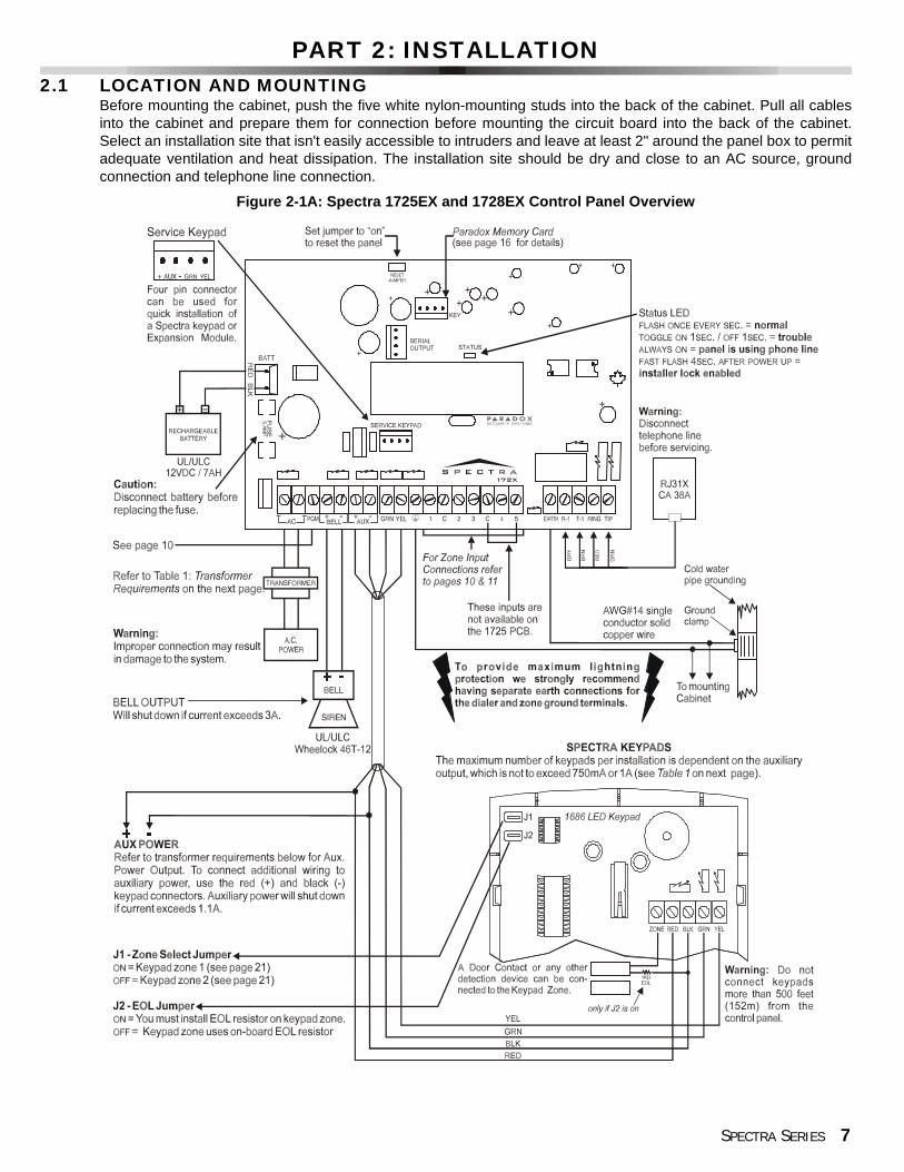
Before mounting the cabinet, push the five white nylon-mounting studs into the back of the cabinet. Pull all cablesinto the cabinet and prepare them for connection before mounting the circuit board into the back of the cabinet.Select an installation site that isn't easily accessible to intruders and leave at least 2" around the panel box to permitadequate ventilation and heat dissipation. The installation site should be dry and close to an AC source, groundconnection and telephone line connection.
Figure 2-1A: Spectra 1725EX and 1728EX Control Panel Overview

8 REFERENCE & INSTALLATION MANUAL
2.2 EARTH GROUNDConnect the zone and dialer ground terminals from the control panel to the cabinet and cold water pipe or groundingrod as per local electrical codes.
For maximum lightning protection, use separate earth grounds for the zone and dialer grounds asshown in Figure 2-1.
2.3 AC POWERDo not use any switch-controlled outlets to power the transformer. Connect the transformer as shown in Figure 2-1.Use Table 1 to determine the required transformer.
Table 1: Transformer Requirements Table
Transformer: Min. 16VAC 20VAUL: Amseco XP-1640
Rec. 16VAC 40VAUL: Amseco XP-1640
Spectra DC Power Supply rated at: 1.2A 1.5AAuxiliary Supply can provide a maximum of: 750mA 1AAcceptable Battery Charge Currents (see page 41) 350mA 350mA/700mA
Figure 2-1B: Spectra 1755EX and 1758EX Control Panel Overview Other than the location of the parts on the board and the items that have been indicated below, connections to these control panels are identical to those on page 7.

SPECTRA SERIES 9
2.4 BACK UP BATTERYIn order to provide power during a power loss, connect a 12VDC 7Ah rechargeable acid/lead or gel cell back up batteryas shown in Figure 2-1. Connect the back up battery after applying AC power. When installing verify proper polarity, asreversed connections will blow the battery fuse. Also, refer to Battery Charge Current on page 41.
2.4.1 BATTERY TESTIf the battery is disconnected a "No/Low Battery" failure will appear in the keypads’ Trouble Display (seepage 54). This trouble will also appear if the battery’s capacity is too low or if the voltage drops to 10.5 voltsor lower while the control panel is running on the back up battery. At 8.5 volts or lower, the panel shutsdown and all outputs close.
2.5 AUXILIARY POWER TERMINALSThe auxiliary power supply terminals can be used to power motion detectors, keypads and other modules oraccessories in the security system. A fuseless circuit protects the power supply against current overload andautomatically shuts down if the current exceeds 1.1A. If this occurs the “Maximum Auxiliary Current” failure will appearin the keypads’ Trouble Display (see page 54). Therefore, the combined current consumption of devices connected tothe auxiliary power supply should not exceed 1A (with 40VA transformer) or 750mA (with 20VA transformer). Auxiliarypower will resume once the overload condition has restored.
2.6 TELEPHONE LINE CONNECTIONIn order to report system events to the central station you must connect the incoming telephone company wires intothe TIP and RING connections of the control panel. Then run the wires from T1 and R1 to the telephone ortelephone system as shown in Figure 2-1.
2.7 BELL OUTPUT CONNECTIONThe BELL+ and BELL- terminals power bells, sirens and other warning devices requiring a steady voltage outputduring an alarm. The bell output supplies 12VDC upon alarm and can support two 20-watt or two 30-watt sirens.The bell output uses a fuseless circuit and will automatically shut down if the current exceeds 3A (1725EX/1728EX)or 2.5A (1755EX/1758EX). When this occurs the “Maximum Bell Current” failure will appear in the keypads’ TroubleDisplay (see page 54). If the load on the BELL terminals returns to normal, the control panel will re-instate power tothe BELL terminals. When connecting sirens (speakers with built-in siren drivers) please verify correct polarity.Connect the positive lead to the BELL+ terminal and the negative lead to the BELL- terminal of the control panel asshown in Figure 2-1. Please note that the 1755EX and 1758EX have an optional siren driver. When the siren driveris enabled (see page 29), you do not have to use a speaker with a built-in siren driver. You can connect a regularspeaker directly to the BELL output.
If the BELL output is not being used, the "Bell Disconnected" failure will remain in the keypads’Trouble Display (see page 54). To avoid this, connect a 1kΩ resistor across the BELL terminals.
Table 2: Current Consumption Table
Modules Current ConsumptionSpectra 1686H and 1686V 10-Zone LED Keypad 62mA typ. 116mA max.Spectra 1689 16-Zone LED Keypad 50mA typ. 117mA max.Spectra 1639 LCD Keypad 60mA typ. 80mA max.LiberatorTM Wireless Bus Expansion Module 65mA typ. 65mA max.8-Zone Hardwire Expansion Module 40mA typ. 40mA max.4-Zone Hardwire Expansion Module 12mA typ. 12mA max.Motion Detectors (see detector instructions for details) 10-50mA typ.

10 REFERENCE & INSTALLATION MANUAL
2.8 PROGRAMMABLE OUTPUT CONNECTIONSThe Spectra Series control panels include one or more programmable outputs (PGMs).When a specific event occurs in the system, a PGM can reset smoke detectors, activatestrobe lights, open/close garage doors and much more. PGM1 provides a maximum50mA output and PGM2 provides up to 2.5A and can be used as a strobe output (seepage 40). PGM2 is limited by the power source being used. If powered by the BELL+terminal, the combined current consumption of the bell output and PGM2 must notexceed 2.5A. If it is powered by the aux.+, the devices connected to the auxiliary powersupply and PGM2 must not exceed 1.1A. If it is powered by an external device, PGM2can supply 2.5A. If the current draw on the PGM is to exceed the current output, werecommend the use of a relay as shown in Figure 2-2. For details on how to program thePGM, refer to PGM Programming on page 39.
2.9 ALARM RELAYThe Spectra 1755EX and 1758EX control panels have an optional 5A relay. This relay can be connected as shownin Figure 2-1B on page 8. Please note that the Alarm Relay can be programmed to follow the bell output or theactivation and de-activation of PGM2 (see Alarm Relay Options on page 40).
2.10 SINGLE ZONE INPUTSDetection devices such as motion detectors and door contacts are connected to the control panel's zone inputterminals labeled between 1 and 5 depending on the Spectra control panel being used. Figure 2-8 demonstratessingle zone input terminal connections recognized by the Spectra Series control panels. Once connected, theassociated zone's parameters must be defined. For more information, please refer to Zone Programming onpage 20.
Figure 2-2: PGM
Figure 2-3: Single Zone Input Connections

SPECTRA SERIES 11
2.11 DOUBLE ZONE INPUTS (WITH ATZ OPTION ONLY)Enabling the ATZ feature (see page 25) allows you to install two detection devices per input terminal. The ATZfeature is a software-oriented feature. Therefore, there is no need for extra modules, simply connect the devices asshown in Figure 2-4. Devices connected to input terminals must be assigned to a zone and the zone's parametersmust be defined. Please refer to Zone Programming on page 20 of this manual for more information. The status ofeach zone will be displayed on the keypads and the control panel can send separate alarm codes for each zone.
2.12 KEYPAD INSTALLATIONTo connect the keypads to the control panel, remove the back cover and wire the GRN, YEL, RED, and BLKterminals of each keypad to the corresponding terminals on the control panel as shown in Figure 2-1 on page 7.There is no limit to the number of keypads that can be connected to the control panel so long as the currentconsumption does not surpass the maximum current consumption of the control panel's Auxiliary Power Terminals(see page 9). For information on Keypad Tamper Supervision refer to page 42 and for information on Keypad ZoneConnections refer to page 11.
2.13 KEYPAD ZONE CONNECTIONSEach keypad has one zone input terminal, allowing you to connect one motion detector or door contact directly to akeypad. The keypad can then communicate the status of the zone to the control panel. A maximum of two keypadzones can be used with each control panel. After connecting the device as shown in Figure 2-1 on page 7, thezone's parameters must be defined. For more information on zone recognition and Zone Programming refer topage 20.
Example: A door contact located at the entry point of an establishment can be wired directly to the input terminal ofthe entry point keypad instead of wiring the door contact all the way to the control panel.
2.14 KEYSWITCH CONNECTIONSKeyswitches allow users to arm or disarm a partition by pushing button or by activating aswitch with a key. You must enable zone 2 as a Keyswitch Zone (see page 22), connectthe keyswitch to zone input terminal 2 as shown in Figure 2-5 and program theKeyswitch Options as described on page 24.
2.15 FIRE CIRCUITSWhen zone 3 is defined as a 24Hr. zone (see page 22), the control panel will recognize zone 3 as a Fire Zone,enabling smoke detectors to be connected as shown in Figure 2-6. Fire zones must use a 1kΩ EOL resistor. If thereis a line short or if the smoke detector becomes active, whether the system is armed or disarmed, the control panelwill generate an alarm.
Figure 2-4: Double Zone (ATZ) Input Connections
Figure 2-5: Keyswitch
12 REFERENCE & INSTALLATION MANUAL
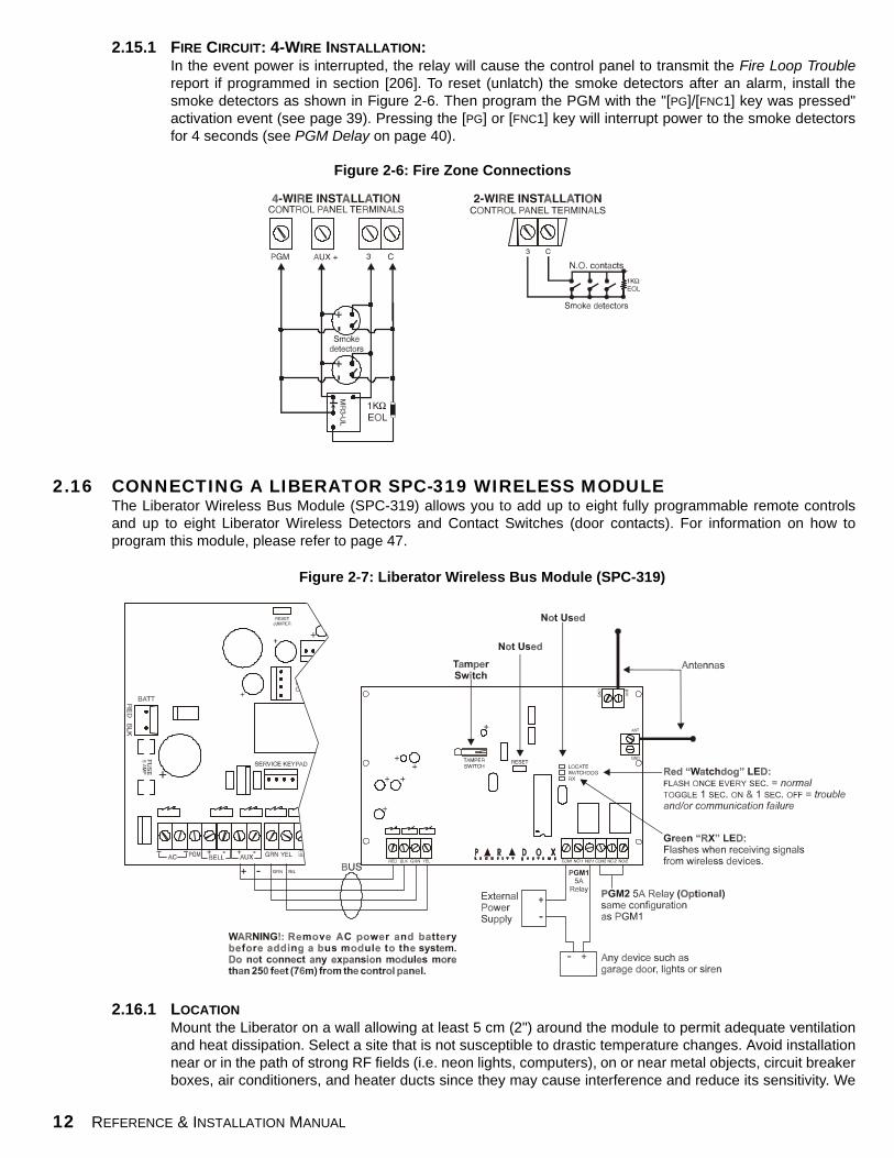
2.15.1 FIRE CIRCUIT: 4-WIRE INSTALLATION:In the event power is interrupted, the relay will cause the control panel to transmit the Fire Loop Troublereport if programmed in section [206]. To reset (unlatch) the smoke detectors after an alarm, install thesmoke detectors as shown in Figure 2-6. Then program the PGM with the "[PG]/[FNC1] key was pressed"activation event (see page 39). Pressing the [PG] or [FNC1] key will interrupt power to the smoke detectorsfor 4 seconds (see PGM Delay on page 40).
2.16 CONNECTING A LIBERATOR SPC-319 WIRELESS MODULEThe Liberator Wireless Bus Module (SPC-319) allows you to add up to eight fully programmable remote controlsand up to eight Liberator Wireless Detectors and Contact Switches (door contacts). For information on how toprogram this module, please refer to page 47.
2.16.1 LOCATIONMount the Liberator on a wall allowing at least 5 cm (2") around the module to permit adequate ventilationand heat dissipation. Select a site that is not susceptible to drastic temperature changes. Avoid installationnear or in the path of strong RF fields (i.e. neon lights, computers), on or near metal objects, circuit breakerboxes, air conditioners, and heater ducts since they may cause interference and reduce its sensitivity. We
Figure 2-6: Fire Zone Connections
Figure 2-7: Liberator Wireless Bus Module (SPC-319)

SPECTRA SERIES 13
recommend installing it in a centralized location on the main floor. Avoid installing it in the basement.
2.16.2 CONNECTIONS AND MOUNTING Firmly screw the two antennas into the connectors marked "ANT" on the Liberator Wireless Bus Module asshown in Figure 2-7. Using a drill or screwdriver, punch out the four mounting holes on the back of theplastic case. Align the six holes of the printed circuit board with the six pins on the back plastic mountingcase and snap into place. If placed correctly, the antennas will lean directly over the grooves in themounting case. Connect the “GRN” and “YEL” terminals from Wireless Module to the corresponding “GRN”and “YEL” terminals of the control panel. Connect the “RED” terminal to the “AUX+” of the control panel.Connect the “BLK” terminal to the “AUX-” of the control panel. Please refer to Figure 2-7.
The Liberator Module does not function with the Spectra 1755EX and 1758EX control panels. Do notcut, bend, or alter the antennas. Avoid mounting the Receiver Module near or on metal as this may affectits sensitivity. Remove AC power and then remove the battery before adding a bus module to the systemor it may cause communication trouble. Do not connect more than one Liberator Wireless Module tothe control panel.
2.17 CONNECTING A ZONE EXPANSION MODULE (SPC-ZX4/ZX8)The Zone Expansion Modules connect to the Spectra control panel's communication bus providing you with up to 4(SPC-ZX4) or up to eight (SPC-ZX8) additional hardwired inputs and one 50mA on-board PGM output. For informationon how to program these modules, please refer to page 50. Connect the four terminals labeled RED, BLK, GRN and YELof each Zone Expansion Module to the corresponding terminals on the control panel as shown in Figure 2-8.
Do not connect more than one Zone Expansion Module to the control panel. The ZX4 module is identicalto the ZX8 except there are no LEDs and there are only four zone inputs (Z1 to Z4) instead of eight.
2.17.1 ZONE CONNECTIONS (SPC-ZX4/SPC-ZX8)Each input terminal, allows you to connect one detection device. These devices are connected exactly asshown in Figure 2-3 on page 10. Devices connected to the Zone Expansion Module's input terminals mustbe enabled as described in Zone Input Assignment on page 50 and the its parameters must be defined as
Figure 2-8: Zone Expansion Module (SPC-ZX8)

14 REFERENCE & INSTALLATION MANUAL
explained in Zone Programming on page 20. The Zone Expansion Modules will communicate the status ofthe zones to the control panel through the communication bus.
The Zone Expansion Modules do not support the zone doubling (ATZ) feature.
2.17.2 ZONE EXPANSION MODULE TAMPER CONNECTIONSThe Zone Expansion Modules do not come equipped with a tamper switch. Although, if required you canenable Tamper Recognition (Zone Module) (see page 50), which will reserve input terminal Z1 as a tamperswitch input. This allows you to connect a tamper switch to input Z1 as shown in Figure 2-8. When atamper is detected on the module, it will send a tamper report (originating from the zone assigned to inputZ1) to the control panel via the communication bus.
With Zone Expansion Module Tamper Recognition enabled, do not connect anything otherthan the tamper switch to input terminal Z1.

SPECTRA SERIES 15
PART 3: PROGRAMMING METHODS3.1 WINLOAD SOFTWARE FOR WINDOWS
Program the Spectra Series control panels remotely or on-site using the Winload Upload/Download Software for Windows®.For more information, contact your local Paradox Distributor or visit our web site at http://www.paradox.ca.
3.2 PROGRAMMING USING A KEYPADUse the supplied "Spectra Programming Guide" to keep track of which sections were programmed and how. Werecommend you read this entire manual before you begin programming.
3.2.1 SINGLE DIGIT DATA ENTRY METHOD (HEXADECIMAL AND DECIMAL)Single Digit Data Entry is used in all sections except those specified in Multiple Feature Select ProgrammingMethod. After entering the programming mode as described in the shaded box above, some sections willrequire that you enter Decimal values from 000 to 255. Other sections will require that you enter Hexadecimalvalues from 0 to F. The required data will be clearly indicated in this manual as well as in the Spectra SeriesProgramming Guide. When entering the final digit in a section, the control panel will automatically save andadvance to the next section. With the exception of sections 001 to 016, where after entering the first two digits,the control panel will switch to Multiple Feature Select Programming.
3.2.2 MULTIPLE FEATURE SELECT PROGRAMMING METHODSections: [001] to [016], [127] to [138], [302] to [348], [610], [650] to [651]After entering the programming mode as described in the shaded box above, each option from [1] to [8] willrepresent a specific feature or option. Press the key corresponding to the desired option and thecorresponding light will illuminate or the option number will appear in the LCD display. This means the option ison. Press the key again to extinguish the corresponding light or remove the digit from the LCD display, thereby,turning off the option. Please note that pressing the [FORCE] key will set all 8 options to “off”. Press the keys asmany times as you need until all 8 options in the current section are set. When the options are set, press the[ENTER] key to save and advance to the next section.
How Do I Enter Programming Mode?STEP 1: Press [ENTER]STEP 2: Enter your [INSTALLER CODE] (default: 000000)
STEP 3: Enter 3-digit [SECTION] you wish to program
STEP 4: Enter required [DATA]
Table 3: Decimal and Hexadecimal Programming Table
Value or Action What Do I Press?
What Do I See?10-Zone LED 16-Zone LED LCD
Values 1 to 9 [1] to [9] [1] to [9] [1] to [9] [1] to [9]A (hexa only) [0] [0 (10)] [10] AB (hexa only) [STAY] [STAY] [11] BC (hexa only) [BYP] [BYP] [12] CD (hexa only) [MEM] [MEM] [13] DE (hexa only) [TBL] / [TRBL] [TBL] [14] EF (hexa only) [PG] / [FNC1] [PG] [15] F
Insert Blank Digit [FORCE] Displays next digit or next sectionExit Without Saving [CLEAR] [ENTER] flashes [ARM1] & [STAY1] flash “SECTION [ ]”
Save Data (hexa only) [ENTER] Advances to the next section

16 REFERENCE & INSTALLATION MANUAL
3.2.3 DATA DISPLAY MODE (LED KEYPADS ONLY)In the Data Display Mode you can view the programmed contents of each section one digit at a time. Afterentering the desired 3-digit section (see step 3 of the “How Do I Enter The Programming Mode” box on theprevious page), press the [ENTER] key to access the Data Display Mode. This mode will not function withsections using the Multiple Feature Select Programming Method.
3.3 PROGRAMMING USING A PARADOX MEMORY CARDCopy the programmed contents of one Spectra control panel into the Paradox Memory Card. Then copy thecontents of the Paradox Memory Card into as many Spectra control panels as you need. This saves you a lot oftime, all you have to do is program one Spectra control panel, then download the programmed contents to othercontrol panels in less than 5 seconds.
Download to DESTINATION Control Panel1) Insert the Memory Card onto the serial connector labeled “KEY” of the Spectra control
panel to which you wish to download the contents of the memory card to. 2) Enter section [900]3) When the keypad emits a “confirmation beep”, remove the Memory Card.
Copy to Memory Card from SOURCE Control Panel1) Insert Memory Card onto the serial connector labeled “Key” of the Spectra control panel
from which you wish to copy. Make sure the write protect jumper is on.2) Enter section [902]3) When the keypad emits a “confirmation beep”, remove Memory Card. Remove the
jumper if you do not wish to accidentally overwrite the contents of the card.
Figure 3-1: Data Display Mode (LED Keypads Only)
Figure 3-2: Paradox Memory Card

SPECTRA SERIES 17
PART 4: ACCESS CODESThe Spectra Series control panels support the following 48 access codes:
4.1 ACCESS CODE LENGTH
Section [127] = System OptionsOption [2] OFF = 6-Digit Access Codes Option [2] ON = 4-Digit Access Codes (default)
All access codes can be set to lengths of either 4 or 6-digits. When the 4-digit option is selected, entering a 4-digitcode will allow access. Using the 6-digit option, entering 6 digits is required to allow access.
If the Access Code Length is changed from four digits to six digits when access codes havealready been programmed, the control panel will automatically add the last 2 digits by using thefirst 2 digits. For example, if the access code is 1234 and you switch to 6 digits, the code willbecome 123412. Be sure to verify the access codes after switching from 4-digit access codes to 6-digit codes. When switching from six digits to four digits, the control panel will simply remove thefinal two digits of the access code. For example, 123456 will become 1234.
4.2 INSTALLER CODE (Default: 000000) The Installer Code is used to enter the control panel's programming mode (see page 15), which allows you toprogram all the features, options and commands of the control panel. The Installer Code can be 4 or 6-digits inlength (see above) where each digit can be any value from 0-9. The Installer Code cannot be used to program theMaster or User Access Codes. To program the Installer Code press:
[ENTER] + [CURRENT INSTALLER CODE] + [281] + new 4 or 6-digit Installer Code
4.3 SYSTEM MASTER CODE (Default: 123456)With the System Master Code a user can use any arming method and can program any User Access Code but not theUser Code Options described on page 17. The System Master Code can be 4 or 6 digits in length (see above), whereeach digit can be any digit from 0 to 9. To change the System Master Code press:
[ENTER] + [CURRENT SYSTEM MASTER CODE] + [301] + new 4 or 6-digit System Master Code
4.4 USER CODE OPTIONSSections [302] to [348] - Feature Select Method: Options [1] to [7] on/off The User Code Options define which arming methods each user can use to arm or disarm the system. Regardlessof these settings, all users can Regular Arm assigned partitions and all users except those with the Arm Only optioncan disarm an assigned partition, regardless of how it is armed. Select one or more of the options described on thefollowing pages for each User Access Code, where sections [302] to [348] represent User Access Codes 002 to048. For information on how User Access Codes are programmed, please refer to page 55.
INSTALLER CODE: Used to program all control panel settings except User Access Codes.SYSTEM MASTER CODE (001) Provides full access. Arm and disarm using any method described in the User Code
Options on page 17 as well as program the User Access Codes.MASTER CODE 1 (002): Permanently assigned to partition 1. Same as a regular User Code except it can
also program access codes for User Codes assigned to partition 1.MASTER CODE 2 (003): Permanently assigned to partition 2. Same as a regular User Code except it can
program access codes for User Codes assigned to partition 2. If the system is not partitioned Master Code 002 will be assigned to partition 1.
45 USER CODES (004-048): Can arm and disarm as per User Code Options on page.

18 REFERENCE & INSTALLATION MANUAL
4.4.1 PARTITION 1 ASSIGNMENTSections [302] to [348] = User Codes 002 - 048Option [1] OFF = Deny access to partition 1 Option [1] ON = User code has access to partition 1 (default)
If Partitioned (see page 41), user codes with this option enabled can arm and disarm partition 1.
If the system is not partitioned, you must assign partition 1 to the User Access Code.Otherwise, the User Access Code will be considered disabled.
4.4.2 PARTITION 2 ASSIGNMENTSections [302] to [348] = User Codes 002 - 048Option [2] OFF = Deny access to partition 2 (default)Option [2] ON = User code has access to partition 2
If the system is partitioned (see page 41), user codes with this option enabled can arm and disarm partition2. If the system is not partitioned, the control panel ignores this option.
4.4.3 BYPASS PROGRAMMINGSections [302] to [348] = User Codes 002 - 048Option [3] OFF = Bypass Programming Disabled Option [3] ON = Bypass Programming Enabled (default)
User codes with this option enabled can perform Bypass Programming in assigned partitions.
4.4.4 STAY ARMINGSections [302] to [348] = User Codes 002 - 048Option [4] OFF = Stay Arming Disabled Option [4] ON = Stay Arming Enabled for selected User Code (default)
User codes with this option enabled can Stay Arm assigned partitions.
4.4.5 FORCE ARMINGSections [302] to [348] = User Codes 002 - 048Option [5] OFF = Force Arming Disabled (default)Option [5] ON = Force Arming Enabled for selected User Code
User codes with this option enabled can Force Arm assigned partitions.
4.4.6 ARM ONLYSections [302] to [348] = User Codes 002 - 048Option [6] OFF = Arm Only Disabled (default)Option [6] ON = Arm Only Enabled for selected User Code
The user code with this option enabled can arm assigned partitions but can not disarm any partitions. The typeof arming is dependent on the other User Code Options selected. Please note that with the Arm Only option,the user can cancel a recently armed system by re-entering the access code before the end of the Exit Delay.
4.4.7 PGM ACTIVATIONSections [302] to [348] = User Codes 002 - 048Option [7] OFF = Arm, Disarm & PGM activation for selected User Code (default)Option [7] ON = PGM only for selected User Code
With option [7] off, entering the access code will arm or disarm the system as well as activate or deactivatea PGM. The appropriate PGM Activation/Deactivation Event must also be programmed (see page 39).With option [7] on, the control panel will ignore all other User Code Options. Therefore, entering the accesscode will only activate or deactivate the PGM.
SPECTRA SERIES 19
4.5 LOCK MASTER CODESection [127] = System OptionsOption [4] OFF = Lock System Master Code Disabled (default)Option [4] ON = Lock System Master Code Enabled
With this feature enabled, the control panel will lock the System Master Code (001). This means that pressing theSystem Master Code cannot be deleted but it can be changed.
4.6 DURESS CODESection [127] = System OptionsOption [6] OFF = Duress Code Disabled (default)Option [6] ON = User Code 048 becomes a Duress code
With this feature enabled, User Code 048 becomes a Duress Code. When forced to arm or disarm their system,users can enter a Duress Code (User Code 048) to arm or disarm the system which can immediately transmit asilent alert to the Central Station, transmitting the duress report code programmed in section [196].

20 REFERENCE & INSTALLATION MANUAL
PART 5: ZONE PROGRAMMINGWhen programming zones please note that the Spectra control panels’ zone assignment is dependent on where thedetection devices in the system are connected (see Table 4 below).
What is an Expansion Input?There are a total of eight expansion inputs available. Each hardwired input on a Zone Expansion Module or wireless transmitterused by the Liberator Wireless Bus Module can be assigned to an expansion input. The expansion inputs can be used in anycombination. For example, you can assign four wireless transmitters as well as 4 hardwire inputs to the expansion inputs.Regardless of how many expansion modules are being used, the control panel cannot support more than eight expansioninputs. The expansion module inputs are assigned as follows:
SPC-319 Liberator Wireless Bus ModuleWireless transmitters assigned to sections [601] to [608] of the control panel represent expansion inputs 1 to 8 respectively.For more information, please refer to Wireless Transmitter Assignment on page 47.
SPC-ZX4 and SPC-ZX8 Zone Expansion ModuleDetection devices connected to input terminals Z1 to Z4 of the SPC-ZX4 module or Z1 to Z8 of the SPC-ZX8 module,represent expansion inputs 1 to 8 respectively. Please note that the module’s inputs must be enabled in section [651] of thecontrol panel. For more information, please refer to Zone Input Assignment on page 50.
Do not assign inputs from different modules to the same expansion input. For example, do not assign awireless transmitter to section [601], then connect a detection device to input Z1 of the SPC-ZX8 and enableoption [1] in section [651].
After connecting a hardwired detection device to one of the control panel's or zone expansion module’s input terminals orafter setting up any wireless transmitters, you must define the associated zone's parameters. The Zone Parameters definethe type of zone, the zone's partition assignment and how the control panel will react when an alarm condition occurs on thatzone as described in the following sections. These Zone Parameters are programmed into one section as detailed in Figure5-1 (see next page). For more information on the Installation of detection devices to the control panel and its expansionmodules, please refer to page 4.
Table 4: Zone Recognition Table
Device connected to which input?
1725EX/1755EX 1728EX/1758EXNO ATZ WITH ATZ NO ATZ WITH ATZ
Control Panel Input 1 = Zone 1 Zone 1 & 4 Zone 1 Zone 1 & 6Control Panel Input 2 = Zone 2 Zone 2 & 5 Zone 2 Zone 2 & 7Control Panel Input 3 = Zone 3 Zone 3 & 6 Zone 3 Zone 3 & 8Control Panel Input 4 = N/A N/A Zone 4 Zone 4 & 9Control Panel Input 5 = N/A N/A Zone 5 Zone 5 & 10
Keypad Zone 1 = Zone 4 Zone 7 Zone 6 Zone 11Keypad Zone 2 = Zone 5 Zone 8 Zone 7 Zone 12
Expansion Input 1 = Zone 6 Zone 9 Zone 8 Zone 13Expansion Input 2 = Zone 7 Zone 10 Zone 9 Zone 14Expansion Input 3 = Zone 8 Zone 11 Zone 10 Zone 15Expansion Input 4 = Zone 9 Zone 12 Zone 11 Zone 16Expansion Input 5 = Zone 10 Zone 13 Zone 12 N/AExpansion Input 6 = Zone 11 Zone 14 Zone 13 N/AExpansion Input 7 = Zone 12 Zone 15 Zone 14 N/AExpansion Input 8 = Zone 13 Zone 16 Zone 15 N/A

SPECTRA SERIES 21
5.1 ZONE DEFINITIONSAs demonstrated in Figure 5-1, sections [001] to [016] represent zones 1 through 16 respectively, where the firstdigit in each of these sections represents the zone's definition. To disable a zone, clear the contents of the sectioncorresponding to the desired zone by pressing the [FORCE] key 3 times and pressing [ENTER]. There are 6available Zone Definitions, which are described as follows.
5.1.1 ENTRY DELAY 1 Sections [001] - [016] = Zones 1 - 16: First Digit = 1When the system is armed and when a zone defined with Entry Delay 1 opens, the control panel willgenerate an alarm after the programmed Entry Delay 1 Timer has elapsed. This is to provide users withenough time to enter the protected area and disarm the system. To program the Entry Delay 1 Timer, key inthe desired 3-digit delay value (000-255 seconds, Default = 45 seconds) into section [069]. Entry Delayzones are commonly used at the entry/exit points of the protected area (i.e. front/back door, garage, etc.).Using different Entry Delays (see Entry Delay 2 below) is useful when, for example, one entry pointrequires a longer delay than the other entry point, or in a partitioned system where each partition mayrequire a different Entry Delay. Also, refer to Zone Speed on page 25.
5.1.2 ENTRY DELAY 2Sections [001] - [016] = Zones 1 - 16: First Digit = 2Entry Delay 2 zones are identical to Entry Delay 1 zones (see page 21), except it uses a separate EntryDelay Timer. To program the Entry Delay 2 Timer, key in the desired 3-digit delay value (000-255 seconds,Default = 45 seconds) into section [070]. Also, refer to Zone Speed on page 25.
Press the[ENTER] key
Key in3-digit [SECTION]
Zone DefinitionFirst Digit
Zone OptionsFeature Select
Enter the[INSTALLER CODE]
Zone Definitions1 - Entry Delay 12 - Entry Delay 23 - Follow 4 - Instant 5 - 24Hr. BurglaryIf zone 2 = Keyswitch ZoneIf zone 3 = Fire Zone6 - 24Hr. BuzzerIf zone 3 = Delayed Fire Zone
Zone Options[1] Auto Zone Shutdown Enabled[2] Bypass Enabled[3] Stay Zone[4] [5] Zone Alarm Typeoff off Audible Alarm (steady)off on Audible Alarm (pulsed)on off Silent Alarmon on Generates only a report[6] Intellizone[7] Delay alarm transmission[8] Force Zone
Keyswitch OptionsOnly if Zone 2 = keyswitch zone[1] off = Maintained
on = Momentary[2] off = Regular Arm
on = Stay Arm
Selectone
Press [ENTER]
[001] = Zone 1 [009] = Zone 90[002] = Zone 2 [010] = Zone 10[003] = Zone 3 [011] = Zone 11[004] = Zone 4 [012] = Zone 12[005] = Zone 5 [013] = Zone 13[006] = Zone 6 [014] = Zone 14[007] = Zone 7 [015] = Zone 15[008] = Zone 8 [016] = Zone 16
Zone PartitionAssignmentSecond Digit
Selectone
Zone Partition Assignment1- Zone Assigned to Partition 12- Zone Assigned to Partition 23- Zone Assigned to Both Partitions
Keypads beep twice
Figure 5-1: Spectra Zone Programming
22 REFERENCE & INSTALLATION MANUAL
5.1.3 FOLLOW ZONESSections [001] - [016] = Zones 1 - 16: First Digit = 3When an armed Follow Zone opens, the control panel will immediately generate an alarm, unless an EntryDelay zone opens first: • If an armed Follow Zone opens after an Entry Delay zone opens, the control panel waits until the Entry
Delay Timer has elapsed before generating an alarm.• If an armed Follow Zone opens after more than one Entry Delay zone opens, the control panel will wait
until the Entry Delay Timer of the zone that opened first has elapsed.This feature is commonly used when a motion detector is protecting the area occupied by the entry pointkeypad. This will prevent the motion detector from causing an alarm when a user enters through the entrypoint to disarm the system. Also, refer to Zone Speed on page 25.
5.1.4 INSTANT ZONES
Sections [001] - [016] = Zones 1 - 16: First Digit = 4When an armed Instant Zone opens, the control panel immediately generates an alarm. Instant Zones arecommonly used for windows, patio doors, skylights and other perimeter type zones. Also, refer to ZoneSpeed on page 25.
5.1.5 24HR. BURGLARY ZONES / FIRE ZONE / KEYSWITCH ZONESections [001] - [016] = Zones 1 - 16: First Digit = 5
24Hr. Burglary ZonesWhenever a 24Hr. Burglary Zone opens, whether thesystem is armed or disarmed, the control will panelimmediately generate an alarm. Also, refer to ZoneSpeed on page 25.
Keyswitch Zone If zone 2 is defined as a 24Hr. Burglary Zone itimmediately becomes a Keyswitch Zone (first digit insection [002] = 5). Connecting a keyswitch to zone 2 allowsusers to arm the system by pressing a button or by turninga switch on or off. Please refer to Keyswitch Connectionson page 11 and to Keyswitch Options on page 24.
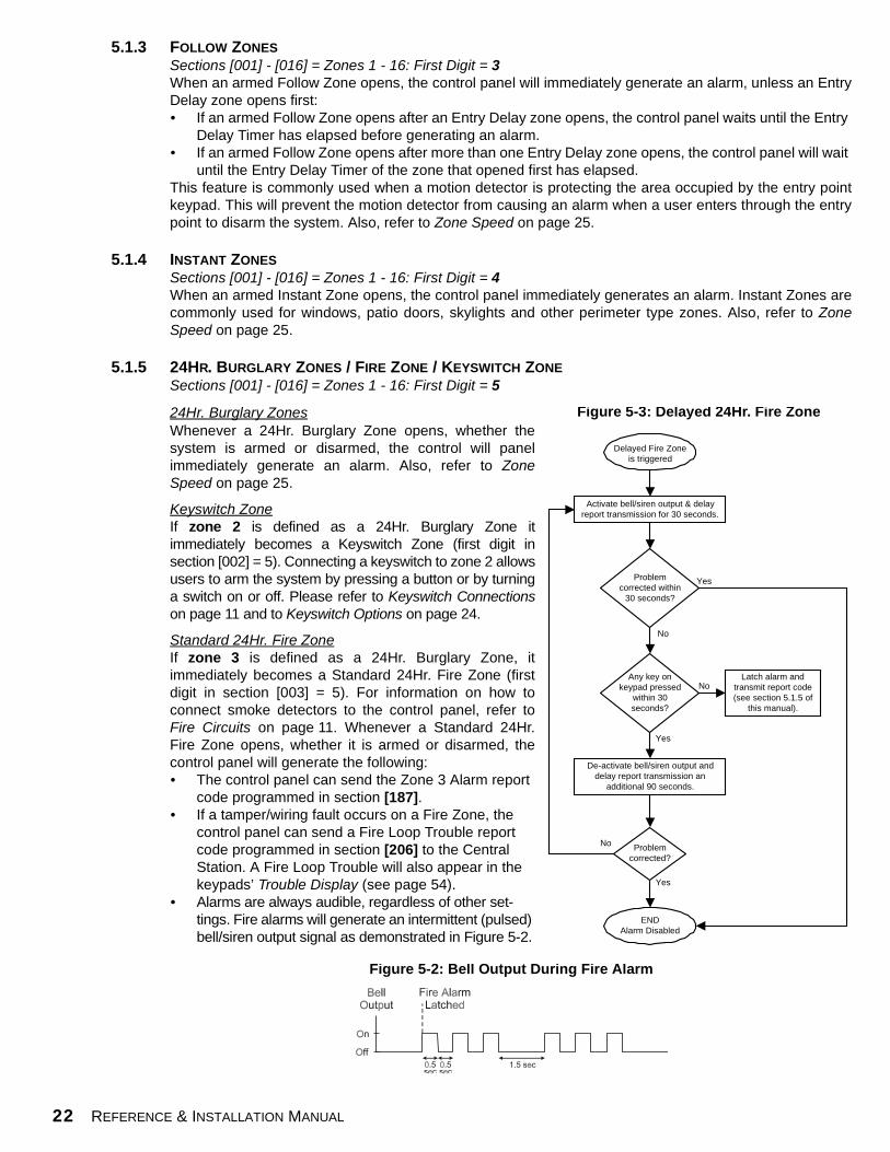
Standard 24Hr. Fire ZoneIf zone 3 is defined as a 24Hr. Burglary Zone, itimmediately becomes a Standard 24Hr. Fire Zone (firstdigit in section [003] = 5). For information on how toconnect smoke detectors to the control panel, refer toFire Circuits on page 11. Whenever a Standard 24Hr.Fire Zone opens, whether it is armed or disarmed, thecontrol panel will generate the following:• The control panel can send the Zone 3 Alarm report
code programmed in section [187]. • If a tamper/wiring fault occurs on a Fire Zone, the
control panel can send a Fire Loop Trouble report code programmed in section [206] to the Central Station. A Fire Loop Trouble will also appear in the keypads’ Trouble Display (see page 54).
• Alarms are always audible, regardless of other set-tings. Fire alarms will generate an intermittent (pulsed) bell/siren output signal as demonstrated in Figure 5-2.
Delayed Fire Zoneis triggered
Activate bell/siren output & delayreport transmission for 30 seconds.
Yes
Any key onkeypad pressed
within 30seconds?
De-activate bell/siren output anddelay report transmission an
additional 90 seconds.
Problemcorrected?
Latch alarm andtransmit report code(see section 5.1.5 of
this manual).
ENDAlarm Disabled
Yes
Yes
No
Problemcorrected within
30 seconds?
Yes
No
No
Figure 5-3: Delayed 24Hr. Fire Zone
Figure 5-2: Bell Output During Fire Alarm

SPECTRA SERIES 23
5.1.6 24HR. BUZZER / DELAYED FIRE ZONESections [001] - [016] = Zones 1 - 16: First Digit = 6Whenever a 24Hr. Buzzer Zone opens, whether the zone is armed or disarmed, the control panel sets offthe keypads’ buzzers to indicate the zone was breached. The control panel will report the alarm but will notenable the bell/siren output. Enter any valid access code on the keypad to stop the buzzer. This zonedefinition is particularly useful when a user wishes to be notified when something such as a safe or lockerwithin the home has been accessed (i.e. a child accessing a valuable collection).
Delayed 24Hr. Fire ZoneIf zone 3 is defined as a 24Hr. Buzzer Zone it immediately becomes a Delayed 24Hr. Fire Zone (first digit insection [003] = 6). Commonly used in residential homes where a smoke detector often generates false alarms(i.e. burning bread, etc.), Delayed 24Hr. Fire Zones function as described in Figure 5-3 on previous page.
If the ATZ feature is enabled (see page 25) when using a Keyswitch or any type of Fire Zone,the control panel will disable the “doubled zone” (see Zone Doubling on page 25).
5.2 ZONE PARTITION ASSIGNMENTSections [001] - [016] = Zones 1 - 16:Zone is assigned to Partition 1 if second digit = 1, Partition 2 if second digit = 2, Both partitions if second digit = 3
As demonstrated in Figure 5-1 on page 21, sections [001] to [016] represent zones 1 through 16 respectively, where thesecond digit in each of these sections represents the zone's partition assignment. The control panel provides the optionof partitioning the security system into two completely independent systems. Therefore, each zone can be assigned toone partition or both partitions as described in Figure 5-1. For more information on Partitioning, refer to page 41.
5.3 ZONE OPTIONSAs demonstrated in Figure 5-1 on page 21, sections [001] to [016] represent zones 1 through 16 respectively, whereafter entering the first two digits, select one or more of the Zone Options that follow using the Multiple Feature SelectProgramming Method (see page 15).
5.3.1 AUTO ZONE SHUTDOWNSections [001] - [016] = Zones 1 - 16Option [1] OFF = Auto Zone Shutdown Disabled Option [1] ON = Auto Zone Shutdown Enabled for selected zone (default)
If, in a single armed period, the number of alarms generated by a zone with the Auto Zone Shutdownoption enabled exceeds the number defined by the Auto Zone Shutdown Counter, the control panel will nolonger generate an alarm for that zone. To program the Auto Zone Shutdown Counter, key in the desiredlimit (000=Disabled, 001-015, Default = 5) into section [089]. The Auto Zone Shutdown Counter resetsevery time the system is armed.
5.3.2 BYPASS ZONESSections [001] - [016] = Zones 1 - 16Option [2] OFF = Bypass Zone Disabled Option [2] ON = Selected Zone is Bypass Enabled (default)
When a user, utilizes the Bypass Programming feature (see page 57), only zones with the Bypass optionenabled can be programmed as bypassed.
5.3.3 STAY ZONESSections [001] - [016] = Zones 1 - 16Option [3] OFF = Stay Zone Disabled (default)Option [3] ON = Selected Zone is Stay Enabled
Zones with the Stay option enabled will be bypassed when the system is Stay Armed (see page 56).
Do not program a Fire Zone with the Stay option, as the control panel will never bypassFire Zones when Stay Arming.

24 REFERENCE & INSTALLATION MANUAL
5.3.4 ALARM TYPESSections [001] - [016] = Zones 1 - 16
[4] OFF / [5] OFF - Audible Steady (default) When the conditions for an alarm have been met, the control panel can transmit the appropriate ZoneAlarm report code (see page 33) and provides a steady output for any bells or sirens connected to thecontrol panel’s BELL output.
[4] OFF / [5] ON - Audible Pulsed AlarmWhen the conditions for an alarm have been met, the control panel can transmit the appropriate ZoneAlarm report code (see page 33) and provides a pulsed output (see Figure 5-2 on page 23) for any bells orsirens connected to the control panel’s BELL output.
[4] ON / [5] OFF - Silent Alarm When the conditions for an alarm have been met, the control panel can transmit the appropriate ZoneAlarm report code (see page 33) and will not activate the control panel’s BELL output. The appropriate"ARM“ or “STATUS” LED on the keypads will flash to indicate an alarm and the user will still have to disarmthe system.
[4] ON / [5] ON - Report Only When the conditions for an alarm have been met, the control panel can transmit the appropriate ZoneAlarm report code (see page 33). The system will not have to be disarmed.
5.3.5 INTELLIZONESections [001] - [016] = Zones 1 - 16Option [6] OFF = Intellizone Disabled (default)Option [6] ON = Intellizone Enabled for Selected Zone
This feature is used mainly to reduce the possibility of false alarms. When a zone with the Intellizone optionopens, the control panel does not immediately generate an alarm. It begins by triggering the IntellizoneDelay Timer. To program the Intellizone Delay Timer, key in the desired 3-digit value (010-255 seconds,Default = 48 seconds) into section [084]. If any of the following conditions occur during this period, thecontrol panel will generate an alarm:• During the Intellizone Delay, a second zone has caused an alarm.• During the Intellizone Delay, the zone in alarm has restored (closed) and re-occurred (opened).• The zone in alarm remains open for the entire Intellizone Delay.
5.3.6 DELAY BEFORE ALARM REPORT CODE TRANSMISSION Sections [001] - [016] = Zones 1 - 16Option [7] OFF = Delay Alarm Transmission Disabled (default)Option [7] ON = Delay Alarm Transmission Enabled for Selected Zone
When an alarm condition occurs on a zone with this option enabled, the control panel enables the bell/sirenoutput but does not report the alarm to the central station until the end of the Alarm Before Transmission Delay.To program the Alarm Transmission Delay, key in the desired 3-digit delay value (000 = Disabled, 001-255seconds, Default = Disabled) into section [080]. During this period, disarming the system disables the bell/sirenoutput and cancels the report code transmission. This feature is commonly used with Entry Delay zones inorder to reduce the occurrence of false alarms created by new users who may not disarm the system in time.
5.3.7 FORCE ZONESSections [001] - [016] = Zones 1 - 16Option [8] OFF = Force Zone Disabled (default)Option [8] ON = Selected Zone is Force Enabled
Zones with the Force option enabled will be bypassed when the system is Force Armed (see page 57).
Do not program a Fire Zone with the Force option, as the control panel will never bypassFire Zones when Force Arming.
5.3.8 KEYSWITCH OPTIONSIf zone 2 has been programmed as a 24Hr. Burglary Zone (see page 22) it becomes a Keyswitch Zone. In whichcase ignore the Zone Options described in sections 5.3.1 to 5.3.6 of this manual and set the following two options:
SPECTRA SERIES 25
Section [002] - If zone 2 is set as a 24Hr. Burglary ZoneOption [1] OFF = Maintained (default)Option [1] ON = Momentary
To arm the system using the Maintained Keyswitch, set the switch or button to the "on" position. To disarmthe system set the keyswitch to the "off" position. To arm the system using the Momentary Keyswitch, setthe switch or button to the "on" position, then turn it off. Repeating this sequence will disarm the system.
Section [002] - If zone 2 is set as a 24Hr. Burglary ZoneOption [2] OFF = Regular ArmingOption [2] ON = Stay Arming
The control panel can Regular Arm or Stay Arm (see page 56) the system when using a keyswitch.
5.4 ZONE SPEEDSections [050] - [065] = Zones 1 - 16: 001-255 X 10ms, Default = 600msThe Zone Speed defines how quickly the control panel will respond to an open zone. The control panel will notdisplay an open zone on the keypad or generate an alarm until the programmed Zone Speed has elapsed. All otherzone definitions and options do not come into effect until the Zone Speed has elapsed. This feature prevents anymomentary glitches from causing an alarm or unnecessary reporting.
If the ATZ feature is enabled (see section 5.6 below), do not set the Zone Speed to less than50msec. as this may cause false alarms.
5.5 EOL ZONESSection [132] - Zone OptionsOption [4] OFF = Zones do not use EOL resistors (default)Option [4] ON = Zones require EOL resistors
If all detection devices connected to the control panel have input terminals that require 1KΩ end of line resistors, enableoption [4] in section [132]. For more information on the use of EOL resistors, refer to Single Zone Inputs on page 10.
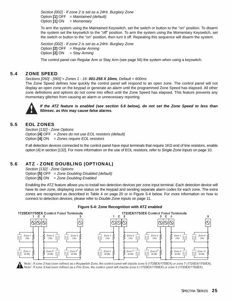
5.6 ATZ - ZONE DOUBLING (OPTIONAL)Section [132] - Zone OptionsOption [5] OFF = Zone Doubling Disabled (default)Option [5] ON = Zone Doubling Enabled
Enabling the ATZ feature allows you to install two detection devices per zone input terminal. Each detection device willhave its own zone, displaying zone status on the keypad and sending separate alarm codes for each zone. The extrazones are recognized as described in Table 4 on page 20 or in Figure 5-4 below. For more information on how toconnect to detection devices, please refer to Double Zone Inputs on page 11.
Figure 5-4: Zone Recognition with ATZ enabled

26 REFERENCE & INSTALLATION MANUAL
PART 6: ARMING AND DISARMING OPTIONS6.1 SWITCH TO STAY ARMING
Section [133] = Partition 1, [134] = Partition 2 Option [7] OFF = Switch to Stay Arming Disabled (default)Option [7] ON = Switch to Stay Arming Enabled
If a user Regular arms a partition but does not exit through (open and close) an Entry Delay zone during the ExitDelay, the control panel can be programmed to switch from Regular Arming to Stay Arming.
6.2 AUTO FORCE ARMING
Section [131] - Arming/Disarming OptionsOption [2] OFF = Auto Force Arming Disabled (default)Option [2] ON = Auto Force Arming Enabled
With this feature enabled, the control panel will always Force arm instead of Regular arm when a valid User AccessCode is entered. In installations where the user must always Force arm when leaving the protected area, thisfeature allows users to Force arm without pressing the [FORCE] key before entering their User Access Code.
6.3 RESTRICT ARMING ON BATTERY FAILSection [130] - Arming/Disarming OptionsOption [5] OFF = Permit arming on battery failure (default)Option [5] ON = Restrict arming on battery failure
If this option is enabled, the control panel will not arm the system if the control panel detects that the back up batteryis disconnected or that the battery voltage drops to less than 10.5V. The control panel will not arm the system untilall battery trouble conditions are rectified.
6.4 RESTRICT ARMING ON TAMPER TROUBLESection [130] - Arming/Disarming OptionsOption [6] OFF = Permit arming on tamper failure (default)Option [6] ON = Restrict arming on tamper failure
If this option is enabled, the control panel will not arm the system if the control panel detects a tamper trouble on oneor more zones. The control panel will not arm the system until all tamper trouble conditions are rectified.
This feature will not function if the Tamper Recognition Options (see page 29) are disabled or wheneverthe tampered zone is bypassed and the Tamper Bypass Options (see page 30) have been enabled.
6.5 TIMED AUTO-ARMINGSection [133] = Partition 1, [134] = Partition 2 Option [1] OFF = Timed Auto-Arming Disabled (default)Option [1] ON = Timed Auto-Arming Enabled
Each partition can be programmed to arm every day at the time specified by the Auto-Arm Timer. The Auto-Arming Options (seepage 27) determine the partition's arming method. The control panel will enter a 60-second Exit Delay period before arming thesystem. At this point, Auto-Arming can be cancelled by entering a valid access code. Once the partition has successfully armed,the control panel can transmit the auto-arming report code programmed in section [172]. If the control panel cannot arm thepartition (i.e. open zone), it will try again on the following day. Regardless of whether the system was successfully armed or not,the control panel will always transmit the Late to Close report code if programmed in section [172]. If Timed Auto-Arming isdisabled, the control panel will still send the Late to Close report code at the time specified by the Auto-Arm Timer.
Example:To automatically arm partition 2 everyday at 6:15PM, enable Timed Auto-Arming for partition 2 by turningon option [1] in section [133]. Then key in 18:15 into section [112].
6.5.1 AUTO-ARM TIMERSection [111] = Partition 1, [112] = Partition 2 Select the section corresponding to the desired partition and program the time (use the 24-hour clock i.e.

SPECTRA SERIES 27
6:30PM = 18:00) you wish the control panel to attempt to arm the selected partition and/or send the Late toClose report code. If Timed Auto-Arming is disabled, the control panel will still send the Late to Closereport code at the time specified by the Auto-Arm Timer.
6.6 NO MOVEMENT AUTO-ARMING Section [133] = Partition 1, [134] = Partition 2 Option [2] OFF = No Movement Auto-Arming Disabled (default)Option [2] ON = No Movement Auto-Arming Enabled
If no movement occurs in a partition's protected area for the period specified by the No Movement Timer (see below),the control panel can automatically arm that partition. The Auto-Arming Option described in section 6.7 of this manualdetermines the partition's arming method. Upon arming, the control panel will transmit the No Movement report code ifprogrammed in section [172]. Regardless of whether the system was successfully armed or not, the control panel willalways transmit the Late to Close report code if programmed in section [172]. If No Movement Auto-Arming isdisabled, the control panel will still send the Late to Close report code at the time specified by the No Movement Timer.
Example: To arm partition 1 whenever there is no movement for a period of 4 hours, enable No Movement Auto-arming forpartition 1 by turning on the [2] Option in section [133]. Then in section [075] enter 016 (16x15min. = 240min. = 4 hours).
6.6.1 NO MOVEMENT TIMERSection [075] = Partition 1, [076] = Partition 2: 001-255 x15min., Default = disabled Select the section corresponding to the desired partition and program the interval of time withoutmovement you wish the control panel to wait before arming and/or send the Late to Close report code. IfNo Movement Auto-Arming is disabled, the control panel can still send the Late to Close report code whenno movement has been detected for the period specified by the No Movement Timer.
6.7 AUTO-ARMING OPTIONSSection [133] = Partition 1, [134] = Partition 2 Option [3] OFF = Regular Arming (default)Option [3] ON = Stay Arming
When using Timed Auto-Arming or No Movement Auto-Arming (see sections 6.5 and 6.6 of this manual), the controlpanel can Regular or Stay Arm (see page 56) the selected partition.
6.8 NIGHT ARMING MODULE OPTIONSThe Spectra Night Arming Module, typically installed in a bedroom, allows users to arm/disarm the system, activatepanic alarms and view system status.6.8.1 PANIC OPTION
Section [133] = Partition 1, [134] = Partition 2 Option [4] OFF= Night Arming Module Panic Disabled (default)Option [4] ON= Night Arming Module Enabled
This feature allows the control panel to generate panic alarms in the selected partition when any two keysare pressed simultaneously on the Spectra Night Arming Module.
6.8.2 ARMING OPTIONSection [133] = Partition 1, [134] = Partition 2 Option [5] OFF= Night Arming Module Arming Disabled (default)Option [5] ON= Night Arming Module Arming Enabled
When enabled, users can arm the selected partition by pressing and holding a key on the Spectra Night ArmingModule for 2 seconds. The Arming Methods feature (see below) determines the partition's arming method.
6.8.3 ARMING METHODS Section [133] = Partition 1, [134] = Partition 2 Option [6] OFF= Night Arming Module performs Regular Arming (default)Option [6] ON= Night Arming Module performs Stay Arming
If the Night Arming Module is enabled (see above) the control panel can Regular or Stay Arm (see page 56).

28 REFERENCE & INSTALLATION MANUAL
6.9 ONE-TOUCH ARMINGSection [130]: Options [1] to [4] see belowOption [1] ON = Press & hold the [ENTER] Option for One-touch Regular Arming.Option [2] ON = Press & hold the [STAY] key for One-touch Stay Arming. Option [3] ON = Press & hold the [FORCE] key for One-touch Force Arming.Option [4] ON = Press & hold the [BYP] key for One-touch Bypass Programming.
The One-touch Arming features allow users to arm the system without having to enter any access codes. To arm thesystem, press and hold the appropriate key (see above) for approximately 2 seconds. If the system is partitioned(see page 41), you must also press the button corresponding to the partition you wish to arm. For more informationon the different arming methods, please refer to page 56.
6.10 EXIT DELAYSection [071] = Partition 1, [072] = Partition 2: 001-255 seconds, Default = 30 seconds After entering the required arming sequence (i.e. User Access code), the Exit Delay parameter determines theamount of time a user has to leave the protected area before the control panel arms the partition. The Exit Delayapplies to all zones in the selected partition.
6.10.1 BEEP ON EXIT DELAYSection [130] - Arming/Disarming OptionsOption [8] OFF = Beep on Exit Delay Disabled Option [8] ON = Beep on Exit Delay Enabled (default)
When enabled, the keypad will beep once every second during the Exit Delay and will beep rapidly duringthe final 10 seconds of the Exit Delay.
6.11 BELL SQUAWK ON ARM/DISARM WITH KEYPADSection [130] - Arming/Disarming OptionsOption [7] OFF = Bell Squawk on Arm/Disarm Disabled (default)Option [7] ON = Bell Squawk on Arm/Disarm Enabled
When this feature is enabled, the bell or siren will "squawk" once upon arming and twice upon disarming.
6.12 BELL SQUAWK ON ARM/DISARM WITH REMOTE CONTROLSection [131] - Arming/Disarming OptionsOption [3] OFF = Bell Squawk on Arm/Disarm with Remote Control Disabled (default)Option [3] ON = Bell Squawk on Arm/Disarm with Remote Control EnabledWhen this feature is enabled, the bell or siren will "squawk" once upon arming with a remote control and twice upondisarming with a remote control.
6.13 NO EXIT DELAY WHEN ARMING WITH REMOTE CONTROLSection [131] - Arming/Disarming OptionsOption [4] OFF = Provides Exit Delay When Arming with a Remote Control (default)Option [4] ON = No Exit Delay When Arming with a Remote Control
With option [4] on in section [131], the control panel will cancel the Exit Delay (arms immediately) when a partition isarmed with a remote control. With option [4] off, the control panel will start the Exit Delay timer when a partition isarmed with a remote control.
6.14 NO AUDIBLE FEEDBACK UPON STAY ARMINGSection [131] - Arming/Disarming OptionsOption [5] OFF = No Audible Feedback On Stay Arming Disabled (default)Option [5] ON = No Audible Feedback On Stay Arming Enabled
With this feature enabled, the control panel will prevent the bell or siren from squawking and the keypads frombeeping during the Exit Delay, whenever a partition is Stay armed.

SPECTRA SERIES 29
PART 7: ALARM OPTIONS7.1 BELL CUT-OFF TIMER
Section [073] = Partition 1, [074] = Partition 2: 000 = Disabled, 001-255 minutes, Default = 4 min. After an audible alarm, the bell or siren will stop upon disarming of the partition or when the Bell Cut-Off Timer haselapsed, whichever comes first.
7.2 SIREN DRIVER OPTIONSSection [129] - General OptionsOption [7] OFF = Siren Driver on Bell Output Disabled (default)Option [7] ON = Siren Driver on Bell Output Enabled
If you have a 1755EX or 1758EX with the siren driver option, enabling this option will allow you to connect a regularspeaker to the BELL output instead of a speaker with a built-in siren driver. Also, refer to Bell Output Connection onpage 9.
7.3 RECYCLE ALARMOnce the Bell Cut-Off Timer has elapsed and after the Recycle Delay has elapsed, the control panel will re-verify thezone status and if there are any open zones, the control panel will generate another alarm. In one armed period, thecontrol panel will repeat this sequence the number of times defined by the Recycle Counter.
7.3.1 RECYCLE ALARM DELAYSection [090]: 000 = disabled, 001-255 minutes, Default = disabledThe Recycle Delay determines the amount of time after Bell Cut-Off that the control panel will wait beforere-verifying zone status.
7.3.2 RECYCLE COUNTERSection [091]: 000 = disabled, 001-255, Default = disabled The Recycle Counter determines the number of times you wish the control panel to re-verify the zonestatus after Bell Cut-Off in one armed period.
7.4 TAMPER RECOGNITION Section [132] - Zone Options
[1] OFF / [2] OFF - Tamper Recognition Disabled (default)The control panel will not perform any action other than generate a standard alarm when a tamper or wire faultoccurs in an armed system. If the system is disarmed, the control panel will display the zone as open in the keypaddisplay but will not generate an alarm. This option is not permitted on UL systems.
[1] OFF / [2] ON - Trouble OnlyWhen a tamper wiring failure occurs on a zone in a disarmed system, a Tamper/Zone Wiring Failure will appear inthe keypads’ Trouble Display (see page 54) and the control panel will transmit the appropriate Zone Tamper reportcode (see page 33). When a tamper wiring failure occurs on a zone in an armed system, the control panel willfollow the zone's Alarm Types setting (see page 24).
[1] ON / [2] OFF - Silent AlarmIn a disarmed system, it functions the same as the "Trouble Only" setting, but it will also generate a silent alarm. Asilent alarm will not trigger any bells or sirens but the system will have to be disarmed. When a tamper wiring failureoccurs on a zone in an armed system, the control panel will follow the zone's Alarm Types setting (see page 24).
[1] ON / [2] ON - Audible AlarmIn a disarmed system, it functions the same as "Trouble Only" setting, except it will also generate an audible alarm.When a tamper wiring failure occurs on a zone in an armed system, the control panel will follow the zone's AlarmTypes setting (see page 24).

30 REFERENCE & INSTALLATION MANUAL
7.4.1 TAMPER BYPASS OPTIONSSection [132] - Zone OptionsOption [3] OFF = Will generate a tamper if detected on a bypassed zone (default)Option [3] ON = Tampers on bypassed zones will be ignored
With option [3] on, the Tamper Recognition feature follows the zone bypass definition. This means thecontrol panel will ignore any tampers detected on a bypassed zone. With option [3] off, Tamper Recognitionignores the bypass definition. This means the control panel will generate an incident as per TamperRecognition settings if a tamper or wire fault occurs on a bypassed zone.
7.5 KEYPAD PANIC OPTIONSSection [128] - General OptionsOption [1] OFF = Emergency Panic DisabledOption [1] ON = Emergency Panic EnabledPressing the [1] & [3] keys simultaneously on the keypad for 2 seconds will generate a silent or audible alarm asdefined by option [4].
Option [2] OFF = Auxiliary Panic DisabledOption [2] ON = Auxiliary Panic EnabledPressing the [4] & [6] keys simultaneously on the keypad for 2 seconds will generate a silent or audible alarm asdefined by option [5].
Option [3] OFF = Fire Panic DisabledOption [3] ON = Fire Panic EnabledPressing the [7] & [9] keys simultaneously on the keypad for 2 seconds will generate a silent or audible alarm asdefined by option [6].
Option [4] OFF = Emergency Panic is SilentOption [4] ON = Emergency Panic is Audible
Option [5] OFF = Auxiliary Panic is SilentOption [5] ON = Auxiliary Panic is Audible
Option [6] OFF = Fire Panic is SilentOption [6] ON = Fire Panic is Pulsed
Silent operation:The control panel emits a confirmation beep and transmits the appropriate Panic report code if programmed insection [195]. The control panel will not enable the keypad buzzers or the control panel’s BELL output (no audiblealarm).
Audible operation:Same as silent operation, except the keypad buzzers and the BELL output will activate until a user cancels the alarm(disarms) with a valid User Access Code or when the Bell Cut-Off Timer elapses (see page page 29).
Fire (pulsed) operation:Same as audible operation, except that the BELL output will be pulsed as shown in Figure 5-2 on page 23.
Whether the system is partitioned or not, the control panel will report all panic alarms to partition 1.

SPECTRA SERIES 31
PART 8: REPORTING AND DIALER SETTINGSThe following section explains all the features and options that must be programmed in order for your security system toproperly report system events to a central station. When an event (e.g. zone in alarm) occurs in the system, the control panelverifies if a report code was programmed in the section corresponding to the event (except Ademco Contact ID “All Codes”).If a report code was programmed, the control panel will dial the central station telephone number defined by the Event CallDirection feature. When the central station answers, the control panel will transmit the System Account Code, followed by theprogrammed Report Code.
Pulse
DTMF(Tone)
Program 1 or 2-digit (1-FF)report codes into sections[160] to [213] where eachsection represents up to 4events in the system.
T h e c o n t r o l p a n e lautomatically generatesall report codes. You donot have to program anyreport codes.
Program the 2-digit reportcodes corresponding to theC o n t a c t I . D . T a b l e i n t osections [160] to [213] whereeach section represents up tofour events in the system.Program FF to use the defaultContact ID Report Code.
"All Codes"Option [3] ON - Section [136]
"Programmable"Option [3] OFF - Section [136]
Central Station Telephone Numbers 1 & 2Sections [151] & [152]
Back-up NumberSection [153]
Partition AccountNumbers
Partition 2 Reporting Account Number 23 or 4 digits (0-F) in Section [144]
Partition Account Number 13 or 4 digits (0-F) in Section [143]Partition 1
Reporting FormatsSection [140]
1st digit = CSTN#12nd digit = CSTN#2
Related Features
Delay Before Alarm TransmissionSection [080]
Pager Format Delay TransmissionSection [083]
Recent Closing DelaySection [085]
Power Failure Report DelaySection [086]
Auto Test ReportSections [087] & [110]
Report Disarm OptionsOption [1] - Section [131]
Report Zone Restore OptionsOption [6] - Section [132]
Reporting/DialerOption [3] - Section [135]
Event Call DirectionDefines which Central Station Telephone Numbers each group ofevents will report to.
Section [137]Option [1] ON = Call Telephone #1 for Arm/Disarm Report CodesOption [2] ON = Call Telephone #2 for Arm/Disarm Report CodesOption [3] ON = Call Telephone #1 for Alarm/Restore Report CodesOption [4] ON = Call Telephone #2 for Alarm/Restore Report CodesOption [5] ON = Call Telephone #1 for Tamper/Restore Report CodesOption [6] ON = Call Telephone #2 for Tamper/Restore Report Codes
Section [138]Option [1] ON = Call Telephone #1 for Trouble/Restore Report CodesOption [2] ON = Call Telephone #2 for Trouble/Restore Report CodesOption [3] ON = Call Telephone #1 for Special System Report CodesOption [4] ON = Call Telephone #2 for Special System Report Codes
Maximum Dialing AttemptsSection [081]
Delay Between DialingAttempts
Section [082]
Alternate DialOption [4] - Section [136]
[1] = Ademco Slow
[3] = Sescoa
[2] = Silent Knight Fast
[4] = Ademco Express
[5] = Ademco Contact ID
[6] = Pager
Figure 8-1: Event Reporting
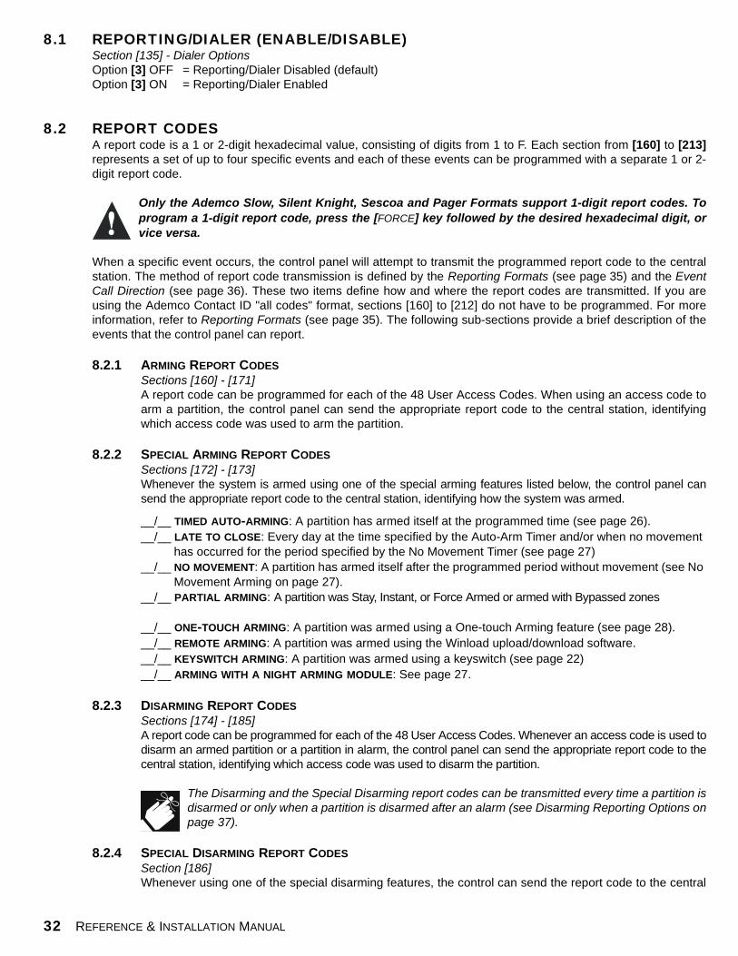
32 REFERENCE & INSTALLATION MANUAL
8.1 REPORTING/DIALER (ENABLE/DISABLE)Section [135] - Dialer OptionsOption [3] OFF = Reporting/Dialer Disabled (default)Option [3] ON = Reporting/Dialer Enabled
8.2 REPORT CODES A report code is a 1 or 2-digit hexadecimal value, consisting of digits from 1 to F. Each section from [160] to [213]represents a set of up to four specific events and each of these events can be programmed with a separate 1 or 2-digit report code.
Only the Ademco Slow, Silent Knight, Sescoa and Pager Formats support 1-digit report codes. Toprogram a 1-digit report code, press the [FORCE] key followed by the desired hexadecimal digit, orvice versa.
When a specific event occurs, the control panel will attempt to transmit the programmed report code to the centralstation. The method of report code transmission is defined by the Reporting Formats (see page 35) and the EventCall Direction (see page 36). These two items define how and where the report codes are transmitted. If you areusing the Ademco Contact ID "all codes" format, sections [160] to [212] do not have to be programmed. For moreinformation, refer to Reporting Formats (see page 35). The following sub-sections provide a brief description of theevents that the control panel can report.
8.2.1 ARMING REPORT CODESSections [160] - [171]A report code can be programmed for each of the 48 User Access Codes. When using an access code toarm a partition, the control panel can send the appropriate report code to the central station, identifyingwhich access code was used to arm the partition.
8.2.2 SPECIAL ARMING REPORT CODES
Sections [172] - [173]Whenever the system is armed using one of the special arming features listed below, the control panel cansend the appropriate report code to the central station, identifying how the system was armed.
__/__ TIMED AUTO-ARMING: A partition has armed itself at the programmed time (see page 26). __/__ LATE TO CLOSE: Every day at the time specified by the Auto-Arm Timer and/or when no movement
has occurred for the period specified by the No Movement Timer (see page 27) __/__ NO MOVEMENT: A partition has armed itself after the programmed period without movement (see No
Movement Arming on page 27).__/__ PARTIAL ARMING: A partition was Stay, Instant, or Force Armed or armed with Bypassed zones
__/__ ONE-TOUCH ARMING: A partition was armed using a One-touch Arming feature (see page 28).__/__ REMOTE ARMING: A partition was armed using the Winload upload/download software. __/__ KEYSWITCH ARMING: A partition was armed using a keyswitch (see page 22)__/__ ARMING WITH A NIGHT ARMING MODULE: See page 27.
8.2.3 DISARMING REPORT CODESSections [174] - [185]A report code can be programmed for each of the 48 User Access Codes. Whenever an access code is used todisarm an armed partition or a partition in alarm, the control panel can send the appropriate report code to thecentral station, identifying which access code was used to disarm the partition.
The Disarming and the Special Disarming report codes can be transmitted every time a partition isdisarmed or only when a partition is disarmed after an alarm (see Disarming Reporting Options onpage 37).
8.2.4 SPECIAL DISARMING REPORT CODESSection [186]Whenever using one of the special disarming features, the control can send the report code to the central

SPECTRA SERIES 33
station, identifying how the system was disarmed.
__/__ CANCEL AUTO-ARM: A partition is disarmed during the Timed Auto-Arm's 60-second exit delay (see page 26). Only if Disarming Reporting Options (see page 37) are set to always report disarming.
__/__ REMOTE DISARM: System disarmed using the Winload upload/download software __/__ KEYSWITCH DISARMING: System disarmed using a keyswitch (see page 22).__/__ DISARMING WITH NIGHT ARMING MODULE: See page 27.
8.2.5 ZONE ALARM REPORT CODESSections [187] - [190]A report code can be programmed for each of the 16 available zones. Whenever a zone generates analarm, the control panel can send the appropriate report code to the central station, identifying which zonegenerated an alarm.
8.2.6 ZONE ALARM RESTORE REPORT CODESSections [191] - [194]A report code can be programmed for each of the 16 available zones. The control panel can transmit thesereport codes to the central station identifying which zone was restored.
A zone is restored when it closes after generating an alarm or once the bell has cut-off after alarmgeneration. Please refer to Zone Restore Report Options on page 38.
8.2.7 SPECIAL ALARM REPORT CODESSections [195] - [196]Whenever the system generates an alarm due to one of the conditions listed below, the control panel cansend the appropriate report code to the central station, identifying the type of alarm.
__/__ EMERGENCY PANIC: Panic keys [1] & [3] have been pressed (see page 30).__/__ AUXILIARY PANIC: Panic keys [4] & [6] have been pressed (see page 30).__/__ FIRE PANIC: Panic keys [7] & [9] have been pressed (see page 30).__/__ RECENT CLOSING: After arming the system, an alarm is generated within period defined by the
Recent Close Delay (see page 37).
__/__ AUTO ZONE SHUTDOWN: A zone communicates more than the programmed number of transmissions in a single armed period (see page 23).
__/__ DURESS: A Duress access code is keyed in (see page 19).
8.2.8 ZONE TAMPER REPORT CODESSection [197] - [200]A report code can be programmed for each of the 16 available zones. Whenever a tamper or wire faultoccurs on a zone, the control panel can send the appropriate report code to the central station, identifyingwhich zone was tampered.
8.2.9 ZONE TAMPER RESTORE REPORT CODESSections [201] - [204]A report code can be programmed for each of the 16 available zones. Whenever a tampered zone isrestored, the control panel can send the appropriate report code to the central station, identifying whichzone has been restored.
If Tamper Recognition (see page 29) is disabled, the control panel will not report the occurrence ofany tampers, wire faults or tamper restores.
8.2.10 SYSTEM TROUBLE REPORT CODESSection [205] - [207]Whenever the system generates one of the instances listed below, the control panel can send theappropriate report code to the central station, identifying the type of system trouble.
__/__ AC FAILURE: The control panel has detected a loss of AC power. Transmission of this report code can be delayed (see Power Failure Report Delay on page 37).

34 REFERENCE & INSTALLATION MANUAL
__/__ BATTERY FAILURE: Back up battery is disconnected or battery voltage is ≤10.5V.__/__ AUXILIARY SUPPLY: Auxiliary power supply has overloaded (current consumption is >1.1A).
__/__ BELL OUTPUT OVERLOAD: Bell/siren output has overloaded (see page 9).__/__ BELL OUTPUT DISCONNECTED:__/__ TIMER LOSS: The control panel has detected a loss in time or clock failure (see page 41)__/__ FIRE LOOP TROUBLE: The control panel has detected a tamper trouble on a fire zone.
__/__ WIRELESS LOW BATTERY: The battery voltage of a Liberator wireless transmitter (motion detector or contact switch) has dropped to below 6.5V.
__/__ MODULE FAULT: All keypads connected to the control panel have been disconnected. If Zone Expansion Module Supervision has been enabled (see page 43) and the Zone Expansion Module has been disconnected. If Wireless Bus Module Supervision has been enabled (see page 43) and the Liberator Wireless Bus Modules has been disconnected.
__/__ PRINTER FAULT: An error has occurred on the Printer Module.__/__ FAIL TO COMMUNICATE: The control panel has failed all attempts to communicate with the central
station. The report code will be transmitted upon the next successful attempt.
8.2.11 SYSTEM TROUBLE RESTORE CODESSections [208] - [210]Whenever the system restores one of the troubles listed in section 8.2.10, the control panel can send theappropriate report code to the central station, identifying the type of system trouble restore. If TelephoneLine Monitoring is enabled (see page 38), the control panel can also transmit a TLM Restore report code.
8.2.12 SPECIAL REPORTING CODESSections [211] - [213]Whenever the system generates one of the instances listed below, the control panel can send theappropriate report code to the central station, identifying the type of system occurrence.
__/__ COLD START: The control panel was completely shutdown (no battery, no AC), then the control panel was re-started
__/__ TEST REPORT: A test report has been generated automatically (see page 37).__/__ PC CALL BACK: See page 46.__/__ PC ACCESS: The control panel has established communication with the PC software.
__/__ INSTALLER IN: Installer has entered the programming mode.__/__ INSTALLER OUT: Installer has exited the programming mode.
__/__ TX SUPERVISION LOSS: Wireless Transmitter Supervision (see page 47) has been enabled and a transmitter is no longer communicating with the system.
__/__ TX SUPERVISION RESTORE: When the above trouble has been restored
8.3 CENTRAL STATION TELEPHONE NUMBERSSection [151] = Phone#1, [152] = Phone#2, [153] = Back-up Phone#: Up to 32 digits The Spectra Control Panels can dial up to 2 different central station telephone numbers. You can enter any digitfrom 0 to 9 and any special keys or functions (see Table 5 on the next page) up to a maximum of 32 digits. For moreinformation on how these telephone numbers are used, please refer to Event Call Direction on page 36 & ReportingFormats on page 35. After the Maximum Dialing Attempts (see page 37) to one central station telephone numberhave failed, the control panel will then dial the back up telephone number. If the Alternate Dial Option (see page 37)is enabled, the control panel will dial the programmed back up telephone number after every failed attempt. If noback up telephone number is programmed, the control panel will never report to the back-up telephone number.Also refer to Delay Between Dialing Attempts on page 37.

SPECTRA SERIES 35
8.4 PARTITION ACCOUNT NUMBERSSection [143] = Partition 1, [144] = Partition 2All report codes are preceded by a 4-digit or 3-digit Partition Account Number to ensure correct identification in apartitioned system. Partition account numbers can be any hexa-digit from 1 to F. To enter 3-digit account number,simply press the [FORCE] key followed by the 3-digit account number.
8.5 REPORTING FORMATSSection [140]: 1st digit = Format for Phone #1, 2nd digit = Format for Phone #The Spectra Control Panels can use a number of different reporting formats and each Central Station TelephoneNumber can be programmed with a different reporting format. The first digit entered into section [140] represents thereporting format used to communicate with Central Station Telephone Number 1, the second digit represents thereporting format used to communicate with Central Station Telephone Number 2. The Back up Telephone Number usesthe same reporting format as the last Central Station Telephone Number that was dialed.
8.5.1 STANDARD PULSE FORMATSThe Spectra Control Panels can use the Ademco slow, Silent Knight and Sescoa standard pulse reportingformats (see Table 6).
8.5.2 ADEMCO EXPRESSThe Ademco Express is a high-speed reporting format, which will transmit the 2-digit (11-FF) report codesprogrammed into sections [160] to [213]. Unlike other Ademco formats, the Ademco Express does not usethe Contact ID Report Codes.
8.5.3 ADEMCO CONTACT IDAdemco Contact ID is a fast communicator format that uses tone reporting instead of pulse reporting. Thiscommunicator format also uses a pre-defined list of industry standard messages and report codes that willsuit most of your basic installation needs. Please refer to the "Contact ID Report Codes List" in theProgramming Guide for a complete list of these report codes and messages.
8.5.4 CONTACT ID OPTIONSSection [132] - Dialer OptionsOption [3] OFF = Programmable Codes Option [3] ON = All Codes (default)
When using the Programmable Codes format, use the Ademco "Contact ID Report Codes List" in the SpectraProgramming Guide to program the desired report codes into sections [160] to [213]. Enter FF to use the
Table 5: Special Keys for Telephone Numbers
Press Action or Value[STAY] *[BYP] #[MEM] switch from pulse to tone dialing or vice versa
[TBL] or [TRBL] 4-second pause[FORCE] inserts blank digit
Table 6: Reporting Formats
Value Entered Reporting Format 1 Ademco Slow (1400Hz, 1900Hz, 10BPS)2 Silent Knight Fast (1400Hz, 1900Hz, 10BPS)3 SESCOA (2300Hz, 1800Hz, 20BPS)4 Ademco Express (DTMF 4+2)
5 (Default) Ademco Contact ID 6 Pager Format
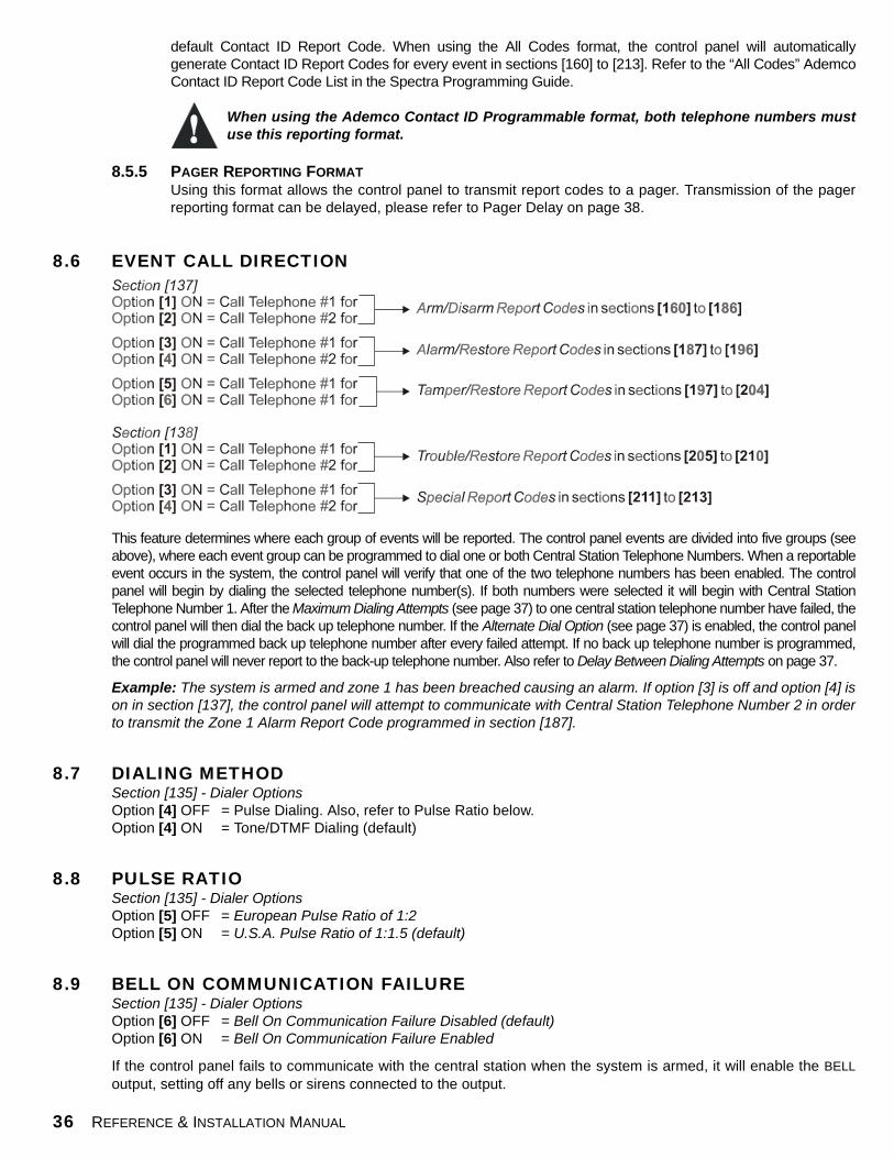
36 REFERENCE & INSTALLATION MANUAL
default Contact ID Report Code. When using the All Codes format, the control panel will automaticallygenerate Contact ID Report Codes for every event in sections [160] to [213]. Refer to the “All Codes” AdemcoContact ID Report Code List in the Spectra Programming Guide.
When using the Ademco Contact ID Programmable format, both telephone numbers mustuse this reporting format.
8.5.5 PAGER REPORTING FORMATUsing this format allows the control panel to transmit report codes to a pager. Transmission of the pagerreporting format can be delayed, please refer to Pager Delay on page 38.
8.6 EVENT CALL DIRECTION
This feature determines where each group of events will be reported. The control panel events are divided into five groups (seeabove), where each event group can be programmed to dial one or both Central Station Telephone Numbers. When a reportableevent occurs in the system, the control panel will verify that one of the two telephone numbers has been enabled. The controlpanel will begin by dialing the selected telephone number(s). If both numbers were selected it will begin with Central StationTelephone Number 1. After the Maximum Dialing Attempts (see page 37) to one central station telephone number have failed, thecontrol panel will then dial the back up telephone number. If the Alternate Dial Option (see page 37) is enabled, the control panelwill dial the programmed back up telephone number after every failed attempt. If no back up telephone number is programmed,the control panel will never report to the back-up telephone number. Also refer to Delay Between Dialing Attempts on page 37.
Example: The system is armed and zone 1 has been breached causing an alarm. If option [3] is off and option [4] ison in section [137], the control panel will attempt to communicate with Central Station Telephone Number 2 in orderto transmit the Zone 1 Alarm Report Code programmed in section [187].
8.7 DIALING METHODSection [135] - Dialer OptionsOption [4] OFF = Pulse Dialing. Also, refer to Pulse Ratio below.Option [4] ON = Tone/DTMF Dialing (default)
8.8 PULSE RATIOSection [135] - Dialer OptionsOption [5] OFF = European Pulse Ratio of 1:2 Option [5] ON = U.S.A. Pulse Ratio of 1:1.5 (default)
8.9 BELL ON COMMUNICATION FAILURESection [135] - Dialer Options Option [6] OFF = Bell On Communication Failure Disabled (default) Option [6] ON = Bell On Communication Failure Enabled
If the control panel fails to communicate with the central station when the system is armed, it will enable the BELLoutput, setting off any bells or sirens connected to the output.

SPECTRA SERIES 37
8.10 DIAL TONE DELAYSection [136] - Dialer Options Option [5] OFF = Dialer will continue to dial if no dial tone is present after 4 seconds (default). Option [5] ON = Dialer will hang-up if no dial tone is present after 16 seconds
8.11 MAXIMUM DIALING ATTEMPTSSection [081]: 001-016 attempts, Default = 8 attemptsThe value programmed here determines how many times the control panel will re-dial the same Central StationTelephone Number before proceeding to the next number.
8.12 DELAY BETWEEN DIALING ATTEMPTSSection [082]: 000-255 seconds, Default = 20 seconds This delay determines the amount of time the control panel will wait between each dialing attempt.
8.13 ALTERNATE DIAL OPTIONSection [136] - Dialer OptionsOption [4] OFF = Alternate Dial Disabled (default)Option [4] ON = Alternate Dial Enabled
With option [4] off, the control panel will dial the back up telephone number programmed in section [153] after allattempts to one Central Station Telephone Number have failed (see Maximum Dialing Attempts on page 37). Withoption [4] on, the control panel will dial the back up telephone number after every failed attempt.
8.14 RECENT CLOSE DELAYSection [085]: 000-255 seconds, Default = no delayIf after having armed the system, an alarm is generated within the period defined by the Recent Close Delay, thecontrol panel will attempt to transmit the Recent Close report code programmed in section [195].
8.15 AUTO TEST REPORTSections [087]: 000=disabled, 001-255 days, default = disabled Section [110]: Time (HH:MM)The control panel will transmit the Test Report report code programmed into section [211] after the number of daysprogrammed into section [087] has elapsed and at the time programmed into section [110]. Use the 24 hour clock toprogram the time (i.e. 6:30PM = 18:30).
8.16 POWER FAILURE REPORT DELAYSection [086]: 001-255 minutes, default = 15 minutesThe control panel will transmit the AC Failure report code programmed in section [205] after the Power FailureReport Delay period has elapsed.
8.17 DISARM REPORTING OPTIONS Section [131] - Arming /Disarming OptionsOption [1] OFF = Always Report DisarmingOption [1] ON = Report Disarming Only After Alarm (default)
With option [1] off, the control panel will send the Disarming report codes (see page 32) to the central station everytime the system is disarmed. With option [1] on, the control panel will send the Disarming report codes to the centralstation when the system is disarmed following an alarm.

38 REFERENCE & INSTALLATION MANUAL
8.18 ZONE RESTORE REPORT OPTIONSSection [132] - Zone OptionsOption [6] OFF = Report On Bell Cut-Off (default)Option [6] ON = Report On Zone Closure
With option [6] off, the control panel will send the Zone Alarm Restore report codes (see page 33) to the centralstation when the zone has returned to normal and the Bell Cut-Off Timer has elapsed (see page 29). With option [6]on, the control panel will send the Zone Alarm Restore report codes to the central station as soon as the zonereturns to normal or when the system is disarmed.
8.19 PAGER DELAYSection [083]: 001-255 seconds, default = 5 secondsWhen using the Pager Reporting Format (see page 36), the control panel will wait for the Pager Delay period beforetransmitting the report codes. This is to allow time for the pager system to provide a dial tone or to bypass the"welcome" message before sending data.
8.20 TELEPHONE LINE MONITORING (TLM) When enabled, the system verifies the existence of a telephone line once every second. A line test failure occurswhen the TLM detects less than 3 volts for the period defined by the TLM Fail Timer. If the line test fails, the controlpanel’s STATUS LED flashes and generates one or more conditions as defined by the TLM settings below. Thesewill be restored when the control panel detects the telephone line again. Please note that when the dialer detects anincoming call, the TLM test will stop for 1 minute.
Section [135] - Dialer Options [1] OFF / [2] OFF - TLM Disabled
[1] OFF / [2] ON - Trouble OnlyUpon line test failure, a TLM Trouble will appear in the keypads’ Trouble Display (see page 54).
[1] ON / [2] OFF - Alarm If System Armed Upon line test failure, a TLM Trouble will appear in the keypads’ Trouble Display (see page 54) and if the system is armed, the control panel will generate an alarm.
[1] ON / [2] ON - Silent Alarm Becomes Audible Upon line test failure, a TLM Trouble will appear in the keypads’ Trouble Display (see page 54) and causes a silent zone or silent panic alarm to switch to audible.
8.20.1 TLM FAIL TIMERSection [079]: 016-255 x 2 seconds, default = 32 secondsIf TLM does not detect the existence of a telephone line for the duration of this period, the control panel willgenerate the condition(s) defined by the TLM options (see above).

SPECTRA SERIES 39
PART 9: PROGRAMMABLE OUTPUTSA PGM is a programmable output that toggles to its opposite state (i.e. a normally open PGM will close) when a specific eventhas occurred in the system. For example, a PGM can be used to reset smoke detectors, activate bells or strobe lights, open/close garage doors and much more. When a PGM closes, the control panel supplies a ground to the PGM activating anydevice or relay connected to it. When a PGM opens, the circuit opens from ground, therefore, cutting power to any devicesconnected to it.
PGM1 A normally open output that provides a maximum of 50mA. Refer to Programmable Output Connections on page 10.
PGM2 Available only on the 1755EX and 1758EX control panels, PGM2 is a normally open output that can provide up to 2.5A.PGM2 was designed to be used as a Strobe Output, for information refer to PGM Strobe Options on page 40. Forspecifications and information on how to connect PGM2, refer to Programmable Output Connections on page 10.
Global PGMThe Global PGM allows you to use the control panel’s PGM Event List to activate PGMs located on a module or LCD keypad.For example, if you were to enable a module’s “Follows Global PGM” option (see pages 49 and 51), the PGM on the modulewould activate whenever the event programmed in section [124] has occurred. Every PGM on every keypad and/orexpansion module can be programmed to follow the event(s) defined by the Global PGM.
9.1 PGM ACTIVATION EVENTSections [120], [122], [124]This feature allows you to program the control panel to activate a PGM when a specific event occurs in the system.The PGM will remain in its active state until the programmed PGM De-Activation Event occurs (see below) or whenthe PGM Delay period has elapsed (see page 40). To program a PGM Activation Event:
1. Enter section that represents the desired PGM. PGM1 = [120], PGM2 = [122], Global PGM = [124] 2. Enter the Event Group # (see PGM table on page 9 of the Spectra Programming Guide). 3. Enter the Sub-Group # (see PGM table on page 9 of the Spectra Programming Guide). 4. Enter the Partition #
01 = Partition 102 = Partition 299 = Both Partitions
Please note that the “AC Loss” PGM Event will only occur after the Power Failure Report Delay haselapsed (see page 37).
9.2 PGM DE-ACTIVATION EVENTSections [121], [123], [125]After PGM activation (see above), the PGM will return to its normal state (deactivate) when the programmed PGMDe-activation Event occurs. Instead of de-activating the PGM on the occurrence of a specific event, the PGM cande-activate after a programmed period has elapsed, please refer to PGM Delay. If using the PGM Delay, thesesections can be used as a second activation event.
1. Enter section that represents the desired PGM. PGM1 = [121], PGM2 = [123], Global PGM = [125]2. Enter the Event Group # (see PGM table on page 9 of the Spectra Programming Guide). 3. Enter the Sub-Group # (see PGM table on page 9 of the Spectra Programming Guide). 4. Enter the Partition #
01 = Partition 102 = Partition 299 = Both Partitions
40 REFERENCE & INSTALLATION MANUAL
9.3 PGM DELAY Section [066] = PGM1, [067] = PGM2, [068] = Global PGM: 000 = Follows De-activation Event, 001-255seconds, Default = 5 secondsInstead of de-activating the PGM on the occurrence of a specific event, the PGM will de-activate after the periodprogrammed here has elapsed.
If a PGM Delay is programmed, the de-activation event can be used as a second activation event.
9.4 PGM2 STROBE OPTIONS (1755EX & 1758EX ONLY)Section [129] - General OptionsOption [1] OFF = PGM2 Output is Steady (Default)Option [1] ON = PGM2 Output is Pulsed (Strobe)With option [1] enabled, PGM2 will flash on and off whenever activated. Otherwise, it will provide a steady output.
Option [2] OFF = PGM2 Pulse When System Armed Disabled (Default)Option [2] ON = PGM2 Pulse When System Armed EnabledWhenever the system is armed, PGM2 will flash once every 30 seconds until the system is disarmed.
Option [3] OFF = PGM2 Pulse on Arm/Disarm Disabled (Default)Option [3] ON = PGM2 Pulse on Arm/Disarm EnabledWith this option enabled, PGM2 will flash once to indicate the system has been armed and will flash twice to indicatethat the system has been disarmed.
9.5 ALARM RELAY OPTIONS (1755EX & 1758EX ONLY)Section [127] - General OptionsOption [7] OFF = Alarm Relay Follows Bell Output (Default)Option [7] ON = Alarm Relay Follows PGM2
With this option off, the optional Alarm Relay will activate or de-activated whenever the Bell Output has activated orde-activated. With the option on, the Alarm Relay will activate or de-activated whenever PGM2 has activated or de-activated.
The Alarm Relay will only follow PGM2 when activated or deactivated by the Activation Event, De-Activation Event or PGM Delay. It will NOT follow PGM2 if activated or de-activated by the StrobeOptions defined in section 9.4.

SPECTRA SERIES 41
PART 10: SYSTEM SETTINGS10.1 HARDWARE RESET
Performing a hardware reset will set all control panel settings to factory default. To perform a power down reset:
1. Make sure the Installer Lock is disabled (see below)2. Remove battery and AC power from the control panel.3. Set the "RESET" jumper to on by placing a jumper on the "RESET" pins of the control panel.4. Re-connect AC and battery power to the control panel.5. Wait 10 seconds and remove the jumper.
10.2 INSTALLER LOCKSection [282]: 000 = Disabled, 147 = Lock Enabled, Default = DisabledProgram 147 into section [282] to lock all programming. Hence, performing a hardware reset as described abovewill not affect the current panel settings. To remove the Installer Lock, enter 000. Please note that four seconds afterresetting the control panel, the STATUS LED on the control panel will flash fast for 5 seconds to indicate that theinstaller lock is enabled.
10.3 BATTERY CHARGE CURRENTSection [127] - General Options Option [5] OFF = Battery Charge Current - 350mA (default)Option [5] ON = Battery Charge Current - 700mA (40VA transformer required)
10.4 PARTITIONINGSection [127] - General Options Option [1] OFF = Partitioning Disabled (default)Option [1] ON = Partitioning Enabled
By enabling partitioning, the alarm system is divided into two distinct systems, identified as Partition 1 and Partition2. When partitioned, each zone and each User Code must be assigned to either Partition 1, Partition 2, or bothpartitions (see Zone Partition Assignment on page 23 and User Code Options on page 17).
• Users can only arm partitions to which they have been assigned.• Only zones assigned to Partition 1 will arm/disarm when Partition 1 is armed or disarmed.• Only zones assigned to Partition 2 will arm/disarm when Partition 2 is armed or disarmed.• Zones assigned to both partitions will arm when both partitions are armed and disarms when at least one partition dis-
arms.• For details on how to arm and disarm partitions, please refer to page 55. • The following features can be programmed separately for each partition: Entry/Exit Delay Timer, Auto-Arming Options,
Night Arming Module Options, Bell Cut-Off Timer, Switch to Stay Arming, PGM Events and Account Numbers.
If the system is not partitioned, all zones, User Codes, and features will be recognized as belongingto partition 1.
10.5 SYSTEM REAL-TIME CLOCK Section [280] Program the current time into section [280] using the 24-hour clock (i.e. 8:30PM = 20:30).
10.6 CLOCK ADJUSTSection [088]: 000 = Disabled, 001-255 (see below), Default = Disabled 001 to 127 = + 1 to +127 seconds128 to 255 = -1 to -127 seconds
If you notice a gain or loss in control panel time, calculate the average gain or loss per day and program the"opposite" amount in order to automatically correct the time setting every 24 hours.

42 REFERENCE & INSTALLATION MANUAL
Example: If a control panel loses 4 minutes per month, this represents an average loss of 8 seconds per day.Therefore, programming 008 (plus 8 seconds) into section [088] would compensate for the 8-second loss.
10.7 KEYPAD TAMPER SUPERVISIONSection [128]: General Options Option [7] OFF = Keypad 1 Tamper Supervision Disabled (default)Option [7] ON = Keypad 1 Tamper Supervision Enabled
Option [8] OFF = Keypad 2 Tamper Supervision Disabled (default)Option [8] ON = Keypad 2 Tamper Supervision Enabled
The control panel can be programmed to monitor the on-board tamper status of one or two keypads in the system. IfKeypad 1 Tamper Supervision is enabled, the control panel will verify the on-board tamper status of a keypad whoseKeypad Zone Jumper (J1) is set to on. If Keypad 2 Tamper Supervision is enabled, the control panel will verify theon-board tamper status of a keypad whose Keypad Zone Jumper (J1) is set to off.
Regardless of whether the keypad zones are being used or not, if more than one keypad has thesame Keypad Zone Jumper setting, Keypad Tamper Supervision will be lost. For example, if two ofthe keypads in your system have the keypad zone jumper (J1) set to on, the control panel will notrecognize a Keypad 1 Tamper Supervision Failure.
If a keypad tamper occurs, the control panel can transmit the appropriate Zone Tamper report code (see page 33)as originating from the zones specified by the Table 7. If the zone specified by the table below has been enabled,the control panel will report the tamper as originating from the partition to which the zone is assigned. If the zone hasnot been enabled, the control panel will send the Zone Tamper report code as originating from partition 1. A Tamper/Zone Wiring Failure will also appear in the keypads’ Trouble Display (see page 54).
10.8 KEYPAD BEEP ON TROUBLESection [127]: General Options Option [3] OFF = Keypad Beep on Trouble Disabled Option [3] ON = Keypad Beep on Trouble Enabled (default)
When enabled, the keypads will emit an intermittent beep tone whenever a trouble condition occurs in the system.The intermittent beep tone will remain activated until the user enters the Trouble Display Mode by pressing the[TBL] or [TRBL] key. The intermittent beeps will be re-initialized whenever a new trouble occurs or the trouble hasrestored and re-occurred.
10.9 INSTALLER QUICK FUNCTIONS KEYSAfter entering the Installer Code, you can press a key to perform specific actions as described below.
10.9.1 INSTALLER TEST MODE[ENTER] + [INSTALLER CODE] + [TBL] OR [TRBL]The Installer Test Mode allows you to perform walk tests where the bell or siren will squawk and thekeypad will emit a confirmation beep to indicate opened zones. To enter this mode, simply enter theInstaller Code then press the [TBL] or [TRBL] key. The keypad will emit a confirmation beep. To disablethis mode, press the [TBL] key again. The keypad will emit a rejection beep.
10.9.2 TEST REPORT[ENTER] + [INSTALLER CODE] + [MEM] Sends the Test Report report code programmed in section [211] to the central station.
Table 7: Zone Tamper Report Code for Keypad Tamper Supervision Failure
Keypad Tamper 1725EX/1755EX 1728EX/1758EXNO ATZ WITH ATZ NO ATZ WITH ATZ
Keypad 1 Tamper Supervision = Zone 4 Zone 7 Zone 6 Zone 11Keypad 2 Tamper Supervision = Zone 5 Zone 8 Zone 7 Zone 12

SPECTRA SERIES 43
10.9.3 CALL UPLOAD/DOWNLOAD SOFTWARE[ENTER] + [INSTALLER CODE] + [BYP] Refer to page 45.
10.9.4 CANCEL COMMUNICATION [ENTER] + [INSTALLER CODE] + [STAY] Cancels all communication until the next reportable event.
10.9.5 ANSWER UPLOAD/DOWNLOAD SOFTWARE[ENTER] + [INSTALLER CODE] + [STAY] Refer to page 46.
10.10 ZONE EXPANSION MODULE SUPERVISIONSection [129]: General Options Option [4] OFF = Zone Expansion Bus Module Supervision Disabled (default)Option [4] ON = Zone Expansion Bus Module Supervision Enabled
By enabling this option, the control panel will supervise the Zone Expansion Module (SPC-ZX4 or SPC-ZX8)connected to the Spectra bus. This means that whenever the Zone Expansion Module is disconnected or isn’tcommunicating with the control panel, the control panel will attempt to transmit the Module Fault report codeprogrammed in section [210] and the Module Loss Failure will appear in the keypads’ Trouble Display (seepage 54).
10.11 LIBERATOR WIRELESS BUS MODULE SUPERVISIONSection [129]: General Options Option [5] OFF = Liberator Wireless Bus Module Supervision Disabled (default)Option [5] ON = Liberator Wireless Bus Module Supervision Enabled
By enabling this option, the control panel will supervise the Liberator Wireless Bus Module (SPC-319) connected tothe Spectra bus. This means that whenever the Liberator Wireless Bus Module is disconnected or isn’tcommunicating with the control panel, the control panel will attempt to transmit the Module Fault report codeprogrammed in section [210] and the Module Loss Failure will appear in the keypads’ Trouble Display (seepage 54).
Functions only with the 1725EX and 1728EX control panels.
10.12 WIRELESS TRANSMITTER LOW BATTERY SUPERVISIONSection [129]: General Options Option [6] OFF = Wireless Transmitter Low Battery Supervision Disabled (default)Option [6] ON = Wireless Transmitter Low Battery Supervision Enabled
When the battery voltage of a Liberator wireless transmitter (motion detector or contact switch) has dropped tobelow 6.5V., the Liberator Wireless Bus Module will send a message to the control panel. By enabling option [6] insection [129], the control panel will attempt to transmit the Wireless Transmitter Low Battery report codeprogrammed in section [210] and the Wireless Transmitter Low Battery Failure will appear in the keypads’ TroubleDisplay (see page 54).
Functions only with the 1725EX and 1728EX control panels.

44 REFERENCE & INSTALLATION MANUAL
10.13 WIRELESS TRANSMITTER SUPERVISION OPTIONS Section [132] - Zone OptionsPlease note that the Liberator Wireless Bus Module Supervision Option must be enabled (see page 47)
[7] OFF / [8] OFF - Supervision Failure Recognition Disabled (default)When a tamper occurs on a wireless transmitter zone in a disarmed system, the control panel will display the zoneas open in the keypad display but will not generate an alarm. When it occurs on in an armed system, the controlpanel will follow the zone's Alarm Types setting (see page 24). This option is not permitted on UL systems.
[7] OFF / [8] ON - Trouble OnlyWhen a tamper occurs on a wireless transmitter zone in a disarmed system, a Wireless Transmitter SupervisionLoss will appear in the keypads’ Trouble Display (see page 54) and the control panel will attempt to transmit the TXSupervision Loss report code programmed in section [213]. When it occurs on in an armed system, the controlpanel will follow the zone's Alarm Types setting (see page 24).
[7] ON / [8] OFF - Silent AlarmWhen a tamper occurs on a wireless transmitter zone in a disarmed system, it functions the same as the "TroubleOnly" setting, but it will also generate a silent alarm. A silent alarm will not trigger any bells or sirens but the systemwill have to be disarmed. In an armed system, the control panel will follow the zone's Alarm Types setting (seepage 24).
[7] ON / [8] ON - Audible AlarmWhen a tamper occurs on a wireless transmitter zone in a disarmed system, it functions the same as the "TroubleOnly" setting, except it will also generate an audible alarm. In an armed system, the control panel will follow thezone's Alarm Types setting (see page 24).
Functions only with the 1725EX and 1728EX control panels.
10.14 RE-PROGRAM ALL EXPANSION MODULESSection [750]After removing an expansion module from the communication bus, the control panel keeps the module’sprogrammed sections in memory. Therefore, if you add or replace a module you can re-program the module with thesettings saved in the control panel. To do so, enter section [750] and press [ENTER].
SPECTRA SERIES 45
PART 11: SETTINGS FOR UP/DOWNLOAD SOFTWARE11.1 PANEL ANSWER OPTIONS
The following two options define how the control panel answers an incoming call from a computer using the ParadoxUpload/Download Software for Windows®.
11.1.1 ANSWERING MACHINE OVERRIDESection [077]: 000 = Disabled, 010-255 seconds, Default = disabledWhen using the upload/download software to communicate remotely with an installation site that uses ananswering machine or service, the answering machine override must be programmed. Using the Upload/download software, call the installation site and on the second ring press the "Enter" key on the keyboardto hang-up. After hanging up, the Upload/download software will immediately call the installation site back.If the installation site is called back within the programmed delay period, the control panel will override theanswering machine or service by picking-up the line after the first ring.
Example: A security installation is using an answering machine set to answer after three rings. If section[077] has been programmed with "040" (40 seconds), when you call the installation site with the softwarethe first time, wait two rings and press "Enter" on the keyboard. The software will hang-up and call theinstallation site back. If the second call is made within 40 seconds, the control panel will pick up the line onthe first ring. If it takes more than 40 seconds, the control panel will not answer on the first ring and theanswering machine will answer after three rings.
11.1.2 NUMBER OF RINGSSection [078]: 000 = disabled, 001-015 rings, Default = 8 rings This value represents the number of rings the control panel will wait before picking-up the line. If the line isnot answered after the number of programmed rings, the control panel will answer the call. Please notethat the control panel resets the "ring" counter every 10 seconds. Therefore, if there is more than 10seconds between each ring, the control panel will reset the counter on the next call.
11.2 PANEL IDENTIFIERSection [141]: 0000-FFFFThis four-digit code identifies the control panel to the upload/download software before initiating communication. Thecontrol panel will verify that the Panel Identifier in the upload/download software is the same. If the codes do notmatch, the control panel will not establish communication. Therefore, be sure to program the same panel identifierinto both the Spectra control panel and the upload/download software.
11.3 PC PASSWORDSection [142]: 0000-FFFFThis four-digit password identifies the PC to the panel, before establishing communication. Program the same PCPassword into both the Spectra control panel and the upload/download software. If the passwords do not match, theUpload/download software will not establish communication.
11.4 PC TELEPHONE NUMBERSection [150]: Up to 32 digitsThe control panel will dial this number when trying to initiate communication with a computer using the upload/download software. You can enter any digit from 0 to 9 and any special keys or functions (see Table 5 on page 35)up to a maximum of 32 digits.
11.5 CALL UPLOAD/DOWNLOAD SOFTWARE[ENTER] + [INSTALLER CODE] + [BYP] The control panel will dial the PC Telephone Number programmed in section [150] in order to communicate with theupload/download software. The control panel and the upload/download software will verify that the Panel Identifierand the PC Password match before establishing communication.
46 REFERENCE & INSTALLATION MANUAL
11.6 ANSWER UPLOAD/DOWNLOAD SOFTWARE[ENTER] + [INSTALLER CODE] + [STAY] In order to perform on-site upload/download connect your computer directly to the control panel using an ADP-1 lineadapter. In Upload/download software go to:
Click Main Menu then click Program Setup and then click Modem & Printer Configuration
Set "Dialing Condition" to "Blind Dial". Program the panel telephone number in upload/download software and followthe instructions on the ADP-1 adapter. When the computer has dialed, press [enter] followed by the Installer Code,then press the [stay] key to manually answer the upload/download software from the control panel.
11.7 AUTO EVENT BUFFER TRANSMISSIONSection [136]: Dialer OptionsOption [2] OFF = Auto Event Buffer Transmission Disabled (default)Option [2] ON = Auto Event Buffer Transmission Enabled
When the event buffer reaches 50% capacity, the control panel will make two attempts to establish communicationwith a PC using the upload/download software by calling the PC Telephone Number programmed in section [150].The upload/download software must be in "wait to dial" mode. When the system establishes communication, it willupload the contents of the event buffer to the upload/download software. If communication is interrupted beforecompleting transmission or if after two attempts, communication is not established, the system will wait until theevent buffer attains another 50% capacity before attempting to re-communicate with the central station. When theEvent Buffer is full, each subsequent new event will erase the oldest event in the buffer.
11.8 CALL BACK FEATURESection [136]: Dialer Options Option [1] OFF = Call Back Disabled (default)Option [1] ON = Call Back Enabled
For additional security, when a PC using the upload/download software attempts to communicate with the controlpanel, the control panel can hang-up and call the PC back in order to re-verify identification codes and re-establishcommunication. When the control panel hangs-up, the upload/download software automatically goes into "wait forcall mode", ready to answer when the control panel calls back. Please note that the PC Telephone Number must beprogrammed in section [150] in order to use the Call Back feature.

SPECTRA SERIES 47
PART 12: LIBERATOR MODULEThe following options and features are only available to program when a Liberator Wireless Bus Module has been connectedto the Spectra control panel’s communication bus as shown on page 12. The Liberator Wireless Bus Module (SPC-319) allowsyou to add up to eight fully programmable remote controls and up to eight Liberator Wireless Detectors and Contact Switches(door contacts). The SPC-319 also provides one programmable 5A relay (PGM). A second 5A programmable relay (PGM) isavailable as an option. A PGM is a programmable output that toggles to its opposite state (i.e. a normally open PGM will close)when a specific event has occurred in the system. For example, a PGM can be used to reset smoke detectors, activate bells orstrobe lights, open/close garage doors and much more. For information on how to connect the Liberator’s PGMs, refer to Figure2-7 on page 13. For information on how to program the Liberator’s PGMs, refer to sections 12.4 to 12.7 of this manual.
The Liberator Wireless Bus Module functions only with the 1725EX and 1728EX control panels. Do notconnect more than one Liberator Module to the control panel.
12.1 WIRELESS TRANSMITTER ASSIGNMENT (LIBERATOR)Sections [601] to [608]: 6-Digit Serial NumberThe first step is to assign each wireless transmitter to a zone in the system. To do so, enter the wireless transmitter’s 6-digitserial number into the appropriate section as described below. The serial number can be located on the inside of thetransmitter or you can use the Serial Number Display method described on page 49 to determine its serial number. Eachsection from [601] to [608] represents Expansion Inputs 1 through 8 respectively. Each Expansion Input represents aspecific zone in the system depending on the type of Spectra control panel being used and whether the ATZ option isenabled. Once the transmitters have been assigned, their associated zones must be programmed as described in ZoneProgramming on page 20. You cannot assign more than 8 wireless transmitters to the Spectra System.
[601] = EXPANSION INPUT 1= [602] = EXPANSION INPUT 2= [603] = EXPANSION INPUT 3= [604] = EXPANSION INPUT 4= [605] = EXPANSION INPUT 5= [606] = EXPANSION INPUT 6= [607] = EXPANSION INPUT 7= [608] = EXPANSION INPUT 8=
Do not assign detection devices from different modules to the same expansion input. For example,do not assign a wireless transmitter to section [601], then connect a detection device to input Z1 ofthe SPC-ZX8 and enable option [1] in section [651].
12.2 SUPERVISION OPTIONS (LIBERATOR)Section [610]: General Options Option [1] OFF = Supervision Disabled (default)Option [1] ON = Supervision Enabled
The Liberator Wireless Bus Module can be programmed to send a Supervision Loss signal to the control panelwhen it has detected that one or more wireless transmitters have not communicated any signals for the perioddefined by the Supervision Timer Setting. The control panel will process this signal as defined by the WirelessTransmitter Supervision Options (see page 44).

48 REFERENCE & INSTALLATION MANUAL
12.2.1 SUPERVISION TIMER SETTINGSection [610]: General Options Option [2] OFF = Check Supervision Every 12 Hours (default)Option [2] ON = Check Supervision Every 12 Minutes
If the Liberator Wireless Bus Module does not receive a signal from one of its wireless transmitters within theperiod defined here, it can send a Supervision Loss signal to the control panel (see page 50).
Supervision Timer must be set to the same value as defined by the jumpers on the wirelesstransmitters.
12.3 ON-BOARD TAMPER RECOGNITION (LIBERATOR)Section [615]: 000 = Disabled, 001-008, Default: DisabledThe Liberator Wireless Bus Module comes equipped with an on-board tamper switch. This feature will allow toreport the Module Tamper through one of the module’s Expansion Inputs (zone). When a tamper is detected on themodule, it will send a Zone Tamper report code to the control panel via the communication bus. The Zone Tamperreport code will originate from the zone defined by the Expansion Input (001-008) you have programmed in section[615]. Please note that the corresponding zone must be programmed (see page 20).
Example: If you program 003 (Expansion Input 3) in section [615] of a Spectra 1725EX panel and the ATZ featureis enabled, when a tamper occurs on the Liberator module, the control panel will transmit the Zone Tamper reportcode as originating from zone 11. Please refer to the table on page 47.
12.4 PGM ACTIVATION EVENT (LIBERATOR)Sections [620] and [622]This feature allows you to program the Liberator to activate its PGMs when a specific event occurs in the system. ThePGM will remain in its active state until the programmed PGM De-Activation Event occurs (see below) or when thePGM Delay period has elapsed (see below). To program a PGM Activation Event:
1. Enter section that represents the desired PGM. PGM1 = [620], PGM2 = [622] 2. Enter the Event Group # (see Liberator PGM table on page 23 of the Spectra Programming Guide).
If you program the “Follows Global PGM” event group, it will follow the event programmed in section [124] 3. Enter the Sub-Group # (see Liberator PGM table on page 23 of the Spectra Programming Guide). 4. Enter the Partition # (see Liberator PGM table on page 23 of the Spectra Programming Guide).
Also, refer to the Follow Global PGM option described on page 49.
12.5 PGM DE-ACTIVATION EVENT (LIBERATOR)Section [621] = PGM1, [623] = PGM2After PGM activation (see above), the PGM will return to its normal state (deactivate) when the programmed PGM De-activation Event occurs. Instead of de-activating the PGM on the occurrence of a specific event, the PGM can de-activate after a programmed period has elapsed, please refer to PGM Delay on page 48.
1. Enter section that represents the desired PGM. PGM1 = [621], PGM2 = [623] 2. Enter the Event Group # (see Liberator PGM table on page 23 of the Spectra Programming Guide).
If you program the “Follows Global PGM” event group, it will follow the event programmed in section [125] 3. Enter the Sub-Group # (see Liberator PGM table on page 23 of the Spectra Programming Guide). 4. Enter the Partition # (see Liberator PGM table on page 23 of the Spectra Programming Guide).
If a PGM’s Delay is programmed in sections [616] or [617], the corresponding de-activation event will beused as another activation event. Also, refer to the Follow Global PGM option described on page 49.
12.6 PGM DELAY (LIBERATOR)Section [616] = PGM1, [617] = PGM2, 000 = Follows De-activation Event, 001-255 sec., Default = 5 sec.After PGM activation, the PGM will de-activate after the period programmed here has elapsed. As soon as a delay

SPECTRA SERIES 49
value (001-255) is programmed, the PGM De-Activation Event becomes a second activation event.
12.7 PGM FOLLOWS GLOBAL PGM (LIBERATOR)Section [610]: General Options Option [3] OFF = PGM1 on Liberator follows Global PGM Disabled (default)Option [3] ON = PGM1 on Liberator follows Global PGM Enabled
Option [4] OFF = PGM2 on Liberator follows Global PGM Disabled (default)Option [4] ON = PGM2 on Liberator follows Global PGM Enabled
Each PGM on the Liberator Wireless Bus Module can be programmed to follow the events and/or PGM Delay Timerdefined by the Global PGM. This means if the option is enabled, the Liberator’s PGM will ignore its activation andde-activation events and timer. Instead it will follow the activation and de-activation events programmed in section[124] and [125] and will follow the Global PGM Delay timer programmed in section [068]. For more information, referto pages 39 and 40.
12.8 SERIAL NUMBER DISPLAY (LIBERATOR)
Section [630]This feature will display the serial number of any Liberator Motion Detector, Contact Switch or Remote Control onany Spectra keypad. To do so:
1. Enter section [630] 2. If it is a Liberator Motion Detector or Contact Switch, press its tamper switch. If it is a Liberator Remote Control,
press any two buttons on the remote control. The keypads will emit a confirmation beep.3. LED Keypads: The serial number digits will appear one at a time by illuminating the corresponding light. To view the next
digit press the [ENTER] key. LCD Keypads: Then entire serial number will appear on the screen.4. Return to step 2 to continue or press [CLEAR] to exit the Serial Number Display.
After entering section [630], ignore the first reading as it will not be accurate.
12.9 SIGNAL STRENGTH DISPLAY (LIBERATOR)Sections [631] to [638]This feature allows you to determine whether the Liberator Module will effectively receive signals from specific wirelessmotion detectors and contact switches. Please note that this feature will only work with wireless transmitters that havealready been assigned to an Expansion Input (zone) as described in Wireless Transmitter Assignment on page 47.After entering the appropriate section as described below, the keypads will display the transmitters relative signalstrength. LED Keypads will illuminate numbers from 1 to 8. LCD keypads will display from 1 to 8 characters on theLCD screen. A reading of 1 is the weakest and a reading of 8 is strongest. Although, an average reading of 3 and up isacceptable. Sometimes moving the transmitter or receiver just a little bit will greatly increase the signal reception.
After entering the desired section, ignore the first reading as it will not be accurate.
Section [631] = Expansion Input 1 = Transmitter Assigned in section [601]Section [632] = Expansion Input 2 = Transmitter Assigned in section [602]Section [633] = Expansion Input 3 = Transmitter Assigned in section [603]Section [634] = Expansion Input 4 = Transmitter Assigned in section [604]Section [635] = Expansion Input 5 = Transmitter Assigned in section [605]Section [636] = Expansion Input 6 = Transmitter Assigned in section [606]Section [637] = Expansion Input 7 = Transmitter Assigned in section [607]Section [638] = Expansion Input 8 = Transmitter Assigned in section [608]
12.10 RESET LIBERATOR MODULESection [640]After entering section [640] and pressing [ENTER], the control panel will reset sections [601] to [623] to default values.

50 REFERENCE & INSTALLATION MANUAL
PART 13: ZONE EXPANSION MODULEThe following options and features are only available to program when a Liberator Zone Expansion Bus Module has been connected tothe Spectra control panel’s communication bus as shown on page 12. The Zone Expansion Modules provide you with up to 4 (SPC-ZX4)or up to eight (SPC-ZX8) additional hardwired inputs and one normally open 50mA PGM output. A PGM is a programmable output thattoggles to its opposite state (i.e. a normally open PGM will close) when a specific event has occurred in the system. For example, a PGMcan be used to reset smoke detectors, activate bells or strobe lights, open/close garage doors and much more. For information on how toconnect the refer to Figure 2-8 on page 13. For information on how to program the PGM, refer to sections 13.4 to 13.6 of this manual.
The Zone Expansion Modules do not support the ATZ feature.
13.1 ZONE INPUT ASSIGNMENT (ZONE MODULE)Section [651]: Options [1] to [8] (see below)After connecting the hardwired detection devices to the Zone Expansion Module’s inputs, you must enable the zoneinputs that are being used. To do so enter section [651] and enable the options that correspond to the module’szone inputs as shown below. When the option is OFF, the input is disabled. The enabled zone inputs are thenautomatically assigned to an Expansion Input. Each Expansion Input represents a specific zone in the systemdepending on the type of Spectra control panel being used and whether the ATZ option is enabled. Once themodule’s zone inputs have been assigned, their associated zones must be programmed as described in ZoneProgramming on page 20. You cannot assign more than 8 additional zones to the Spectra System.
Section [651]
Option [1] ON = ENABLE INPUT “Z1” = EXPAN. INPUT 1 =Option [2] ON = ENABLE INPUT “Z2” = EXPAN. INPUT 2 =Option [3] ON = ENABLE INPUT “Z3” = EXPAN. INPUT 3 =Option [4] ON = ENABLE INPUT “Z4” = EXPAN. INPUT 4 =Option [5] ON = ENABLE INPUT “Z5” = EXPAN. INPUT 5 =Option [6] ON = ENABLE INPUT “Z6” = EXPAN. INPUT 6 =Option [7] ON = ENABLE INPUT “Z7” = EXPAN. INPUT 7 =Option [8] ON = ENABLE INPUT “Z8” = EXPAN. INPUT 8 =
Do not assign detection devices from different modules to the same expansion input. For example,do not assign a wireless transmitter to section [601], then connect a detection device to input Z1 ofthe SPC-ZX8 and enable option [1] in section [651].
13.2 EOL ZONES (ZONE MODULE)Section [650] - OptionsOption [1] OFF = Zones do not use EOL resistors (default)Option [1] ON = Zones require EOL resistors
If all detection devices connected to the Zone Expansion Module have input terminals that require 1KΩ end of line resistors,turn on option [1]. For more information on the use of EOL resistors, refer to Single Zone Inputs on page 10.
13.3 TAMPER RECOGNITION (ZONE MODULE)Section [650]: OptionsOption [2] ON = Tamper Recognition Disabled (default)Option [2] OFF = Reserves Input “Z1” As Tamper Switch Input
The Zone Expansion Modules do not come equipped with a tamper switch. Although, if your installation requires tamperrecognition, enabling this feature will reserve input terminal Z1 of the zone Expansion Module as a tamper input. This allows youto connect a tamper switch to input Z1 as shown in Figure 2.8 on page 13. When a tamper is detected on the module, it will senda Zone Tamper report code to the control panel via the communication bus. The Zone Tamper report code will originate from thezone defined by the Expansion Input (001-008). Please note that the corresponding zone must be programmed (see page 20).
If enabled, do not connect anything other than the tamper switch to input terminal Z1.

SPECTRA SERIES 51
13.4 PGM ACTIVATION EVENT (ZONE MODULE)Sections [656]This feature allows you to program the Zone Expansion Module to activate its PGM when a specific event occurs in thesystem. The PGM will remain in its active state until the programmed PGM De-Activation Event occurs (see below) or whenthe PGM Delay period has elapsed (see below). Also, refer to the Follow Global PGM option described on page 49. Toprogram a PGM Activation Event:
1. Enter section [656] 2. Enter the Event Group # (see Zone Module PGM table on page 26 of the Spectra Programming Guide).
If you program the “Follows Global PGM” event group, it will follow the event programmed in section [124]3. Enter the Sub-Group # (see Zone Module PGM table on page 26 of the Spectra Programming Guide). 4. Enter the Partition # (see Zone Module PGM table on page 26 of the Spectra Programming Guide).
13.5 PGM DE-ACTIVATION EVENT (ZONE MODULE)Sections [657]After PGM activation (see above), the PGM will return to its normal state (deactivate) when the programmed PGM De-activation Event occurs. Instead of de-activating the PGM on the occurrence of a specific event, the PGM can de-activate after a programmed period has elapsed, please refer to PGM Delay below.
1. Enter section [657] 2. Enter the Event Group # (see Zone Module PGM table on page 26 of the Spectra Programming Guide).
If you program the “Follows Global PGM” event group, it will follow the event programmed in section [125] 3. Enter the Sub-Group # (see Zone Module PGM table on page 26 of the Spectra Programming Guide). 4. Enter the Partition # (see Zone Module PGM table on page 26 of the Spectra Programming Guide).
If a PGM’s Delay is programmed in sections [616] or [617], the corresponding de-activation event will be usedas another activation event. Also, refer to the Follow Global PGM option described on page 49.
13.6 PGM DELAY (ZONE MODULE)Section [655]: 000 = Follows De-activation Event, 001-255 seconds, Default = 5 secondsAfter PGM activation, the PGM will de-activate after the period programmed here has elapsed. As soon as a delayvalue (001-255) is programmed, the PGM De-Activation Event becomes a second activation event.
13.7 PGM FOLLOWS GLOBAL PGM (ZONE MODULE)Section [650]: General Options Option [3] OFF = PGM1 on Liberator follows Global PGM Disabled (default)Option [3] ON = PGM1 on Liberator follows Global PGM Enabled
The Zone Expansion Module’s PGM can be programmed to follow the events and/or PGM Delay Timer defined by the GlobalPGM. This means if the option is enabled, the Zone Modules’s PGM will ignore its activation and de-activation events andtimer. Instead it will follow the activation and de-activation events programmed in section [124] and [125] and will follow theGlobal PGM Delay timer programmed in section [068]. For more information, refer to pages 39 and 40.
13.8 RESET ZONE EXPANSION MODULESection [660]After entering section [660] and pressing [ENTER], the control panel will reset sections [650] to [657] to default.

52 REFERENCE & INSTALLATION MANUAL
PART 14: REMOTE CONTROL PROGRAMMINGWhen using the Liberator Wireless Bus Module with a 1725EX or 1728EX control panel or when using the Spectra 1755EX or1758EX control panel with wireless capability built-in, you can program up to 8 remote controls as shown in the followingsections. The remote controls are programmed the same way whether using a Liberator or 1755EX or 1758EX control panel.The only difference is the way the remote controls are assigned. If using a Liberator module, refer to section 14.3 of thismanual. If using the 1755EX or 1758EX control panel, refer to section 14.4
There are two types of hand-held remote controls. There is a 2-button RF transmitter and a 4-button RF transmitter. Eachbutton can perform different actions depending on how the system is programmed. These remote controls can transmit asignal up to a maximum of 30 meters (100ft). The remote controls are powered by a 3V lithium battery. Occasionally thisbattery must be changed as shown in figure 2. References to button 3 and button 4 indicate keys on the 4-button remotecontrol only.
14.1 USER ASSIGNMENTSection [701] to [708]: User Access Code 001 to 048When a user presses a button, the receiver will transmit the assigned User Access Code to the control panel. Thismeans that the remote control only has access to the same user options and partitions defined by the assigned UserAccess Code. Assign the User Access Code (001-048) into the section corresponding to the desired remote control,where sections [701] to [708] represent remote controls 1 through 8 respectively (see Remote Control Assignmenton page 53).
14.2 BUTTON PROGRAMMINGSection [711] to [718]Each button or combination of buttons on every remote control can individually programmed to perform specificactions. Each section from [711] to [718] represents remote controls 1 through 8 respectively (see Remote ControlAssignment on page 53). Each section can be programmed with up to 8 digits. Each digit represents a button orcombination of buttons (see Table 8 on page 53) and each digit can be any value from 1 to D (see Table 9 onpage 53). If a programmed Button Option does not work, it may be because the User Access Code assigned to theremote control does not have access to that feature (User Options).
Figure 14-1: Remote Controls

SPECTRA SERIES 53
14.3 REMOTE CONTROL ASSIGNMENT (LIBERATOR ONLY)Sections [721] to [728]These sections are used to assign up to eight remote controls to the system. After assigning a remote control to thesystem, you must assign a User Access Code and define which actions will be performed by the remote control’sbuttons as explained on page 52. To assign a remote control, enter the remote control’s 6-digit serial number intothe appropriate section where sections [721] to [728] represent remote control numbers 1 through 8. Use the SerialNumber Display method described on page 49 to determine the remote control’s serial number.
14.4 REMOTE CONTROL ASSIGNMENT (1755EX AND 1758EX ONLY)These sections are used to assign up to eight remote controls to the system. After assigning a remote control to thesystem, you must assign a User Access Code and define which actions will be performed by the remote control’sbuttons as explained on page 52. To assign a remote control, enter the appropriate section where sections [731] to[738] represent remote control numbers 1 through 8. Then press a button on the remote control twice, the keypadswill emit a confirmation beep. If you hear a rejection beep, an error has occurred or the remote control has alreadybeen assigned.
Table 8: Button Programming
Sections [711] - [718]
Button or Button Combination
1st Digit = Button A2nd Digit = Button B3rd Digit = Button C (4-button remote only)4th Digit = Button D (4-button remote only)5th Digit = Buttons A & B pressed simultaneously6th Digit = Buttons C & D pressed simultaneously (4-button remote only)7th Digit = Buttons A & C pressed simultaneously (4-button remote only)8th Digit = Buttons B & D pressed simultaneously (4-button remote only)
Table 9: Button Options Table
Digit Value = Button Action1 Regular Arm2 Stay Arm3 Instant Arm4 Force Arm5 Disarm6 Disarm when there is no alarm7 Regular Arm and Disarm8 Generate a Panic 1 Alarm (Police)9 Generate a Panic 2 Alarm (Medical)A Generate a Panic 3 Alarm (Fire)B Activates any PGMs that have Event Group #07 as their Activation EventC Activates any PGMs that have Event Group #08 as their Activation EventD Activates any PGMs that have Event Group #09 as their Activation Event

54 REFERENCE & INSTALLATION MANUAL
PART 15: USER OPERATION
15.1 TROUBLE DISPLAY The Spectra system continuously monitors fourteen possible trouble conditions. When a trouble condition occurs, the[TBL] button or [TRBL] indicator will illuminate on the LED keypads or “Trouble” will appear on the LCD keypad’s screen.Press the [TBL] or [TRBL] button to switch to the Trouble Display. The [TBL] button or [TRBL] indicator will flash andlights corresponding to an existing trouble condition will illuminate on the LED keypads (see Table 10) or theappropriate trouble message will appear on the LCD keypad. Press the [CLEAR] button to exit the Trouble Display.
Please note that the keypad can be programmed to emit a “BEEP” every 5 seconds whenever a new troublecondition has occurred. Pressing the [TBL] or [TRBL] button will stop the “beeping”.
Table 10: Trouble List
LED # Description Details[1] No/Low Battery Failure The control panel performs a dynamic battery test under load every 60 seconds. This trou-
ble indicates that the back-up battery is disconnected or that the battery should be replaced, as it will not provide adequate back-up current in case of AC loss. This trouble will also appear when the control panel is running on battery power and the battery voltage has dropped to 10.5 volts or lower. This means the battery must be recharged or replaced.
[2] Wireless Transmitter Low Battery
This means the battery voltage of a Liberator wireless transmitter has dropped to 6.5V or less. Also, the yellow LED on the transmitter can flash to indicate this trouble. The battery should be replaced.
[3] Power Failure Upon power failure, the AC LED on all keypads will turn off. The control panel can transmit the report code programmed in section [205]. This report code can be delayed by programming a Power Failure Report Delay in section [086]. The AC LED turns back on as soon as power is restored.
[4] Bell or PGM2 Disconnected There is no bell or siren connected to the bell output terminals of the control panel or there is no device connected to the PGM2 terminals (1755EX and 1758EX only). If you are not using the BELL or PGM2 terminals, the trouble indicator will always be on. To avoid this, con-nect a 1KΩ resistor across the bell or PGM2 output.
[5] Maximum Bell Current The BELL output uses a fuseless circuit and will automatically shut down if the current exceeds 3A (1725EX/1728EX) or 2.5A (1755EX/1758EX). After opening the short or reducing the load, the bell current is restored upon the following alarm generation. This trouble indicator will only appear when a condition has occurred that would activate the bell output (e.g. during an alarm).
[6] Maximum Auxiliary Current The auxiliary output uses a fuseless circuit to protect the power supply against current overload and automatically shuts down if the current exceeds 1.1A. After opening the short or reducing the load, the panel will restore power to the auxiliary output.
[7] Communicator Report Fail The control panel has failed all attempts to communicate with the central monitoring station.[8] Timer Loss The control panel’s internal clock must be re-programmed. To re-program the timer
press the [8] key followed by the current time using the 24-hour clock (i.e. 8:30PM = 20:30).
[9] Tamper/Zone Wiring Fail If the Tamper Recognition options are enabled (see page 29), this trouble indicates a wiring problem on one or more zones or that the cover has been removed on one or more wireless transmitters. In order to provide line short recognition the zone connections must have EOL resistors. If you press the [9] key, the keypad will display which zones are in trouble.
[10] Telephone Line Monitoring If the Telephone Line Monitoring (TLM) feature is enabled (see section [135]), this trou-ble indicates that the control panel has not detected the presence of a telephone line for 30 seconds.
[STAY] Fire Loop Trouble Denotes a wiring problem on zone 3, if defined as a Fire Zone.[FORCE] or [16]
Keypad Fault If the keypad is no longer communicating with the control panel, the [TBL] or [TRBL] will flash, the [FORCE] key will illuminate (the LCD keypad displays “Keypad Fault”) and the keypad will emit four consecutive beeps at 5-second intervals. Press any key on the keypad to terminate the “beeping” sequence. When communication has been restored, the system will revert to previous status.
[BYP] Module Loss A Liberator or zone module is no longer communicating with the control panel. [MEM] Wireless Transmitter
Supervision LossOne or more wireless transmitters are no longer communicating with the receiver. If you press the [MEM] key, the keypad will display which zones are in trouble.

SPECTRA SERIES 55
15.2 PARTITIONINGThe Spectra system is equipped with a partitioning feature which can divide the alarm system into two distinct areasidentified as Partition 1 and Partition 2. Partitioning can be used in installations where shared security systems aremore practical, such as a home office or warehouse building. When partitioned, each zone, each User Code andsome of the system's features can be assigned to either Partition 1, Partition 2, or both partitions. If the system isnot partitioned, all zones, User Codes, and features will be recognized as belonging to partition 1.
15.3 PROGRAMMING ACCESS CODESAccess Codes are personal identification numbers that allow you to enter certain programming modes, arm ordisarm your system as well as activate or deactivate PGMs. The Spectra security system supports the following:
System Master Code can arm or disarm any partition using any arming method and can create, modify or delete anyUser Access Code. Only the System Master Code can modify or delete User Access Codes assigned to both partitions.
Master Code 1 is permanently assigned to partition 1 and can be used to create, modify or delete User AccessCodes that are assigned to partition 1.
Master Code 2 is permanently assigned to partition 2 (except when partitioning is disabled, Master Code 2 will be assignedto partition 1) and can be used to create, modify or delete User Access Codes that are assigned to the same partition.
45 User Access Codes (including 1 Duress code)
15.4 DISARMING & DEACTIVATING AN ALARM To disarm an already armed system or to deactivate an alarm simply key in a valid access code. Program adesignated entry/exit point, such as the front door or the garage door with an Entry Delay Timer. When these entry/exit point are opened (breached), it will set off a timer. The system will not generate an alarm until this timer elapses,giving users enough time to enter the premises and disarm the system. Any user can disarm the system, exceptusers have been assigned the Arm Only Option.
How Do I Program Access Codes?
1) Press [ENTER]2) Key in the [SYSTEM MASTER CODE] or [MASTER CODE] 3) Key in 3-digit [SECTION] (see Table below)4) Key in new 4 or 6-digit [ACCESS CODE]
[ENTER] flashes. Return to step 3
How Do I Delete Access Codes?
1) Repeat steps 1 to 3 (see above)2) Press the [FORCE] button once for each digit in the access code (4 or
6 times) until the keypad emits a "CONFIRMATION BEEP"
Section User Codes[001] User Code 001 = System Master Code[002] User Code 002 = Master Code 1[003] User Code 003 = Master Code 2[004] to [047] User Code 004 to User Code 047[048] User Code 048 or Duress Code
How does a partitioned system work?
• Users can only arm/disarm partitions to which they have been assigned. • Only zones assigned to Partition 1 will arm/disarm when Partition 1 is armed or disarmed.• Only zones assigned to Partition 2 will arm/disarm when Partition 2 is armed or disarmed.• Zones assigned to both partitions will arm when both partitions are armed and will disarm when at
least one partition disarms.• Some of the system’s features can be programmed separately for each partition.

56 REFERENCE & INSTALLATION MANUAL
15.5 REGULAR ARMINGThis method, commonly used for day-to-day arming, will arm all the zones in the selected partition. If you make amistake, the keypad will emit a "REJECTION BEEP". When you have correctly armed the system, the appropriate "ARM"indication will turn on and the Exit Delay will be initiated. Please note that Regular Arming can also be activatedusing Auto-Arming, a Keyswitch or using One-Touch Arming.
15.6 STAY ARMINGThis method allows users to remain in the protected area while partially arming the system. For example, whengoing to sleep at night, entry/exit points like doors and windows can be armed while other zones like motiondetectors remain deactivated. Please note that Fire Zones can not be bypassed.
If you make a mistake, the keypad will emit a "REJECTION BEEP". When you have correctly Stay Armed the system,the appropriate “ARM” indication will appear and the Exit Delay will be initiated. Stay Arming can also be activatedusing Auto-Arming, Keyswitch Arming or using One-Touch Arming. Also note that the User Code must have theStay Arming Option enabled.
15.7 INSTANT ARMINGAfter Stay Arming the system and during its Exit Delay, press and hold the [STAY] button for 3 seconds. Youshould hear a "CONFIRMATION BEEP". This will switch all armed zones to Instant zones.
If you have access to both partitions: To Instant Arm one partition, press [STAY] + [ACCESS CODE] + [SELECT PARTITION] + [CLEAR] + press & hold [STAY] To Instant Arm both partitions, press [STAY] + [ACCESS CODE] + [1] + [2] + press & hold [STAY]
How Do I Disarm the System or Deactivate an Alarm?
1) Key in your [ACCESS CODE]The arm or alarm indication will turn off and the keypad will emit a“CONFIRMATION BEEP”.
IF YOU HAVE ACCESS TO BOTH PARTITIONS:2) Press the button corresponding to the partition you wish to Disarm or
to Disarm both partitions, press the [1] key then after the confirmation beep press the [2] key.
How Do I Regular Arm?
1) Green “READY” indicator must be illuminated. Unless the system is partitioned, in which case all zones in the desired partition must be closed.
2) Key a valid [ACCESS CODE]
IF YOU HAVE ACCESS TO BOTH PARTITIONS:3) Press the button corresponding to the partition you wish to Arm. To
Arm both partitions, press the [1] key then after the confirmation beep press the [2] key.
How Do I Stay Arm?
1) All zones in the desired partition (except Stay Zones) must be closed.2) Press the [STAY] button3) Key a valid [ACCESS CODE]
IF YOU HAVE ACCESS TO BOTH PARTITIONS:4) Press the button corresponding to the partition you wish to Stay Arm.
To Stay Arm both partitions, press the [1] key then after the confirmation beep press the [2] key.

SPECTRA SERIES 57
15.8 FORCE ARMINGForce Arming allows users to rapidly arm the system, without having to wait for all zones in the system to be closed.Force Arming is commonly used when a motion detector is protecting the area occupied by a keypad. Therefore,when arming the system, if the motion detector is set as a Force Zone, the control panel will ignore the zone andallow users to arm the system even if the zone is open. Any open Force Zones at the time of arming will beconsidered "deactivated" by the control panel. If during this period a "deactivated" zone is closed, the control panelwill revert that zone to "active" status, hence, will generate an alarm if breached.
If you make a mistake, the keypad will emit a "REJECTION BEEP". When correctly Force Armed, the appropriate "ARM"indication will appear and the Exit Delay will be initiated. Please note that Force Arming can also be activated usingOne-Touch Force Arming. Also note that the Access Code must have the Force Arming Option enabled.
15.9 MANUAL BYPASS PROGRAMMINGManual Bypass Programming allows users to program the alarm system to ignore ("deactivate") specified zones thenext time the system is armed. Please note that Fire Zones can not be bypassed and that Manual BypassProgramming can also be activated using One-Touch Bypass Programming.
*If you have access to both partitions, press the button corresponding to the desired partition. The Access Code musthave the Bypass Programming Option enabled.
15.9.1 BYPASS RECALL FEATUREAfter disarming the system, the control panel will erase the bypass entries. By using the Bypass RecallFeature, you can reinstate the previous bypass entries saved in memory. This eliminates the need tomanually program the bypass entries every time you arm the system.
*If you have access to both partitions, press the button corresponding to the desiredpartition. The Access Code must have the Bypass Programming Option enabled.
15.10 ONE-TOUCH ARMINGOne-Touch Arming allows users to arm the system without the use of an access code.
How Do I Force Arm?
1) All zones in the desired partition (except Force Zones) must be closed.2) Press the [FORCE] button3) Key in a valid [ACCESS CODE]
IF YOU HAVE ACCESS TO BOTH PARTITIONS:4) Press the button corresponding to the partition you wish to Arm. To
Arm both partitions, press the [1] key then after the confirmation beeppress the [2] key.
How do I Program Bypass Entries?
1) Press the [BYP] button.2) Key in a valid [ACCESS CODE]*3) Select one or more [ZONES] you wish to bypass4) Once you have entered the desired bypass entries, press the [ENTER]
button to accept these entries.
How Do I Recall Bypass Entries?
1) Press the [BYP] button.2) Key in your [ACCESS CODE]*3) Press the [BYP] button. Previously bypassed zones will illuminate.4) Press the [ENTER] button.
* If the system is partitioned, press the button corresponding to the desired partition after activating a one-touch feature.

58 REFERENCE & INSTALLATION MANUAL
One-Touch Regular ArmingPress and hold the [ENTER] button for 3 seconds* to arm all zones in the partition. One-Touch Regular Arming can beused to allow specific individuals like service personnel (i.e. cleaners, maintenance) to arm the system when leaving theprotected area, without giving them access to any other alarm system operations.
One-Touch Stay ArmingPress and hold the [STAY] button for 3 seconds* to arm all zones not defined as Stay Zones.
Fast ExitThis feature allows users to exit the already armed premises and keep the system armed. This feature is onlyavailable WHEN THE SYSTEM IS ALREADY STAY ARMED:Exit and Stay Arm: Press and hold the [STAY] button for 3 seconds*. The system will switch to Exit Delay mode. Atthe end of the Exit Delay period, the system will return to Stay Arming.Exit and Regular Arm: Press and hold the [ENTER] button for 3 seconds*. The system will switch to Exit Delay mode.At the end of the Exit Delay period, the control panel will switch to Regular Arming.Exit and Force Arm: Press and hold the [FORCE] button for 3 seconds*. The system will switch to Exit Delay mode.At the end of the Exit Delay period, the control panel will switch to Force Arming.
One-Touch Force ArmingPress and hold the [FORCE] button for 3 seconds* to bypass any open Force Zones.
One-Touch Bypass ProgrammingPress and hold the [BYP] button for 3 seconds* to access Bypass Programming Mode.
15.11 KEYSWITCH ARMINGA keyswitch can be used to arm and disarm the system. Assign the keyswitch to a specific partition and program thekeyswitch to Stay or Regular Arm the assigned partition. Also program the keyswitch to function as a Maintained orMomentary keyswitch. To arm the system using a Maintained Keyswitch, set the keyswitch to the "on" position. To disarmthe system set the keyswitch to the "off" position. To arm the system using a Momentary Keyswitch, set the keyswitch tothe "on" position then turn it back to the "off" position. Repeating this sequence will disarm the system.
15.12 PANIC ALARMSIn case of emergency, the Spectra system provides up to three panic alarms. These panic alarms, if programmed, willimmediately generate an alarm after pressing and holding two specific buttons for two seconds, as described below.
Press and hold buttons [1] and [3] for a panic alarm. Press and hold buttons [4] and [6] for a panic or medical alarm. Press and hold buttons [7] and [9] for a panic or fire alarm.
15.13 AUTO-ARMINGYou can program the Spectra alarm panel to automatically arm upon the following two conditions. The user is onlyallowed to program the Auto Arm Timer. Please note that the control panel will enter a 60-second Exit Delay periodbefore arming the system. At this point, Auto-Arming can be cancelled by entering a valid access code.
15.14 ALARM MEMORY DISPLAYA record of all alarm situations that occur will be stored in memory. After disarming the system, pressing the [MEM]button will display which zones were in alarm during the alarm period. To exit the Alarm Memory Display, press the[CLEAR] button. The control panel will erase the contents of the alarm memory every time the system is armed.
15.15 PROGRAMMING CHIME ZONESThis feature allows users to program which zones will be "Chime Enabled". A "Chime Enabled" zone will cause the keypadto emit a rapid intermittent beep tone (BEEP-BEEP-BEEP-BEEP) advising the user every time it is opened. Each keypad mustbe Chime Programmed separately. Keypad chimes must be re-programmed if the system suffers a total power loss.
10-Zone LED Keypad:Press and hold any button from [1] to [10] for 3 seconds to activate or deactivate Chiming for zones 1 to 10. Forexample, press and hold the [1] button to enable chiming on zone 1. If after pressing and holding a button, the keypad

SPECTRA SERIES 59
emits a confirmation beep, this means the chime feature has been enabled for that zone. If the keypad emits a rejectionbeep, this means the chime feature has been disabled for the corresponding zone.
16-Zone LED Keypad:Press and hold the [9] button. Enter the 2-digit (01 to 16) zone number(s). When the corresponding LED is on, the zoneis chimed. When the corresponding LED is off, the zone unchimed. When the desired zones are chimed, press [ENTER].
LCD Keypad:Press and hold the [9] button. Press the [1] button. Use the arrow keys to scroll through the zones. When theappropriate zone is displayed, press the [FNC1] button until it displays “chimed”. When the desired zones arechimed, press [ENTER].
15.16 KEYPAD MUTINGPress and hold the [CLEAR] button for 3 seconds to enable or disable keypad muting. When muted, the keypad willonly “beep” when a button is pressed or when the keypad emits a rejection or confirmation beep. All other “beep”functions are disabled.

60 REFERENCE & INSTALLATION MANUAL
FCC WARNINGSIMPORTANT INFORMATIONThis equipment complies with Part 68 of the FCC rules subpart D and CS-03. Inside the cover of this equipment is a label that contains,among other information, the FCC registration number of this equipment.
NOTIFICATION TO TELEPHONE COMPANYUpon request, customer shall notify telephone company of particular line to which the connection will be made, and provide the FCCregistration number and the ringer equivalence of the protective circuit.
FCC REGISTRATION NUMBER:5A7CAN-22633 - AL - ERINGER EQUIVALENCE NUMBER:0.1B (U.S. & Canada)USOC JACK: RJ31X (USA), CA31A (CANADA)
TELEPHONE CONNECTION REQUIREMENTSExcept for telephone company-provided ringers, all connections to the telephone network shall be made through standard plugs andtelephone company-provided jacks, or equivalent, in such a manner as to allow for easy, immediate disconnection of terminal equipment.Standard jacks shall be so arranged that, if plug connected thereto is withdrawn, no interference to operation of equipment at customer'spremises which remains connected to telephone network shall occur by reason of such withdrawal.
INCIDENCE OF HARMShould terminal equipment/protective circuitry cause harm to telephone network, telephone company shall, where practicable, notifycustomer that temporary disconnection of service may be required; however, where prior notice is not practicable, the telephone companymay temporarily discontinue service if action is deemed reasonable in circumstances. In case of temporary discontinuance, telephonecompany shall promptly notify customer and will be given opportunity to correct the situation.
CHANGES IN TELEPHONE COMPANY EQUIPMENT OR FACILITIESThe telephone company may make changes in its communication facilities, equipment operations or procedures, where such actions arereasonably required and proper in its business. Should any such changes render customer's terminal equipment incompatible with thetelephone company facilities, the customer shall be given adequate notice to effect the modifications to maintain uninterrupted service.
GENERALThis equipment shall not be used on coin telephone lines. Connection to party line service is subject to state tariffs.
RINGER EQUIVALENCE NUMBER (REN)The ren is useful to determine the quantity of devices that you may connect to your telephone line and still have all of those devices ringwhen your telephone number is called. In most, but not all areas, sum of the ren's of all devices connected to one line should not exceedfive (5.0). To be certain of the number of devices that you may connect to your line, you may want to contact your local telephone company.
EQUIPMENT MAINTENANCE FACILITYIf you experience trouble with this telephone equipment, please contact facility indicated below for information on obtaining service orrepairs. The telephone company may ask that you disconnect this equipment from network until problem is corrected or until you are surethat the equipment is not malfunctioning.
FCC PART 15, WARNINGS INFORMATION TO USERThis equipment has been tested and found to comply with the limits for Class B digital devices, pursuant to Part 15 of FCC rules. Theselimits are designed to provide reasonable protection against harmful interference in a residential installation. This equipment generates,uses and can radiate radio frequency energy, and, if not installed and used in accordance with the instructions, may cause harmfulinterference to radio communications. However, there is no guarantee that interference will not occur in a particular installation. If thisequipment does cause harmful interference to equipment intermittently, the user is encouraged to try to correct the interference by one ormore of the following measures: (1) reorient or relocate the receiving antenna; (2) increase the separation between the equipment andreceiver; (3) connect the equipment to an outlet on a circuit other than the one to which the receiver is connected, or (4) consult the dealeror an experienced radio/tv technician for assistance.
CAUTION: Changes or modifications not expressly approved by PARADOX SECURITY SYSTEMS could void the user's authority to operatethe equipment.
WARRANTYThe Seller warrants its products to be free from defects in materials and workmanship under normal use for a period of one year. Except asspecifically stated herein, all express or implied warranties whatsoever, statutory or otherwise, including without limitation, any implied warranty ofmerchantability and fitness for a particular purpose, are expressly excluded. Because Seller does not install or connect the products and becausethe products may be used in conjunction with products not manufactured by Seller. Seller cannot guarantee the performance of the securitysystem. Seller obligation and liability under this warranty is expressly limited to repairing or replacing, at Seller's option, any product not meeting thespecifications. In no event shall the Seller be liable to the buyer or any other person for any loss or damages whether direct or indirect orconsequential or incidental, including without limitation, any damages for lost profits stolen goods, or claims by any other party, caused by defectivegoods or otherwise arising from the improper, incorrect or otherwise faulty installation or use of the merchandise sold.

SPECTRA SERIES 61
ATTACHMENT LIMITATION NOTICEThe Industry Canada label identifies certified equipment. This certification means that the equipment meets certaintelecommunications network protective, operational and safety requirements. The Department does not guarantee theequipment will operate to the user's satisfaction.
Before installing this equipment, users should ensure that it is permissible to be connected to the facilities of the localtelecommunications company. The equipment must also be installed using an acceptable method of connection. The customershould be aware that compliance with the above conditions may not prevent degradation of service in some situations.
Repairs to certified equipment should be made by an authorized Canadian maintenance facility designated by the supplier.Any repairs or alterations made by the user to this equipment, or equipment malfunctions, may give the telecommunicationscompany cause to request the user to disconnect the equipment.
Users should ensure for their own protection that the electrical ground connections of the power utility, telephone lines andinternal metallic water pipe system, if present, are connected together. This precaution may be particularly important in ruralareas.
CAUTION: Users should not attempt to make such connections themselves, but should contact the appropriate electricalinspection authority, or electrician, as appropriate.
The Load Number (LN) assigned to each terminal device denotes the percentage of the total load to be connected to atelephone loop which is used by the device, to prevent overloading. The termination on a loop may consist of anycombination of devices subject only to the requirement that the total of the Load Numbers of all of the devices does notexceed 100.
Industry Canada certification is only applicable to installation of devices which include transformers approved by theCanadian Standards Association (CSA).
RESTRICTIONS CONCERNANT LE RACCORDEMENT DE MATÉRIELL'étiquette d'Industrie Canada identifie le matériel homologué. Cette étiquette certifie que le matériel est conforme àcertaines normes de protection, d'exploitation et de sécurité des réseaux de télécommunications. Le Ministère garantirtoutefois pas que le matériel fonctionnera à la satisfaction de l'utilisateur.
Avant d'installer ce matériel, l'utilisateur doit s'assurer qu'il est permis de le raccorder aux installations de l'entreprise localede télécommunication. De plus, le matériel doit être installé en suivant une méthode acceptable de raccordement. L'abonnéne doit pas oublier qu'il est possible que la conformité aux conditions énoncées ci-dessus n'empêchent pas la dégradation duservice dans certaines situations.
Les réparations de matériel homologué doivent être effectuées par un centre de service d'entretien canadien autorisédésigné par le fournisseur. La compagnie de télécommunications peut demander à l'utilisateur de débrancher un appareil àla suite de réparations ou de modifications effectuées par l'utilisateur ou à cause d'un mauvais fonctionnement.
Pour sa propre protection, l'utilisateur doit s'assurer que tous les fils de mise à la terre de la source d'energie électrique, deslignes téléphoniques et des canalisations d'eau métalliques, s'il y en a, sont raccordés ensemble. Cette précaution estparticulièrement importante dans les régions rurales.
AVERTISSEMENT: L'utilisateur ne doit pas tenter de faire ces raccordements lui-même; il doit avoir recours à une serviced'inspection des installations électriques, ou à un électricien, selon le cas.
"L'indice de charge (IC) assigné à chaque dispositif indique, pour éviter toute surcharge, le pourcentage de la charge totalequi peut être raccordée à un circuit téléphonique bouclé utilisé par ce dispositif. La terminaison du circuit bouclé peut êtreconstituée de n'importe quelle combinaison de dispositifs, pourvu que la somme des indices de charge de l'ensemble desdispositifs ne dépasse pas 100.
La certification d'Industrie Canada s'applique seulement aux installations d'appareils utilisant un transformateur approuvé parl'Association Canadienne de Normalisation (CSA).
62 REFERENCE & INSTALLATION MANUAL
Numerics24Hr. Buzzer Zone 2324Hr. Delayed Fire Zone 2324Hr. Standard Fire Zone 22AAC Power 8Access Code Length 17Access Code Programming 55Access Codes 17Account Numbers 35Ademco Contact ID 35Ademco Contact ID Options 35Ademco Express 35Adjust Clock 41Alarm Memory Display 58Alarm Options 29Alarm Relay 10Alarm Relay Options 40Alarm Report Code Transmission, Delay 24Alarm Types 24Alternate Dial Option 37Answer Upload/Download Software 43, 46Answering Machine Override 45Arm Only 18Arming and Disarming Options 26Arming Report Codes 32Assigning Wireless Transmitters 47Assigning Zone Inputs (Zone Module) 50ATZ- Zone Doubling 25Auto Event Buffer Transmission 46Auto Force Arming 26Auto Test Report 37Auto-Arming On No Movement 27Auto-Arming On Time 26Auto-Arming Options 27Auxiliary Power 9BBack up Battery 9Battery Charge Current 41Battery, Back up 9Beep On Exit Delay 28Beep On Trouble 42Bell Cut-Off Timer 29Bell on Communication Failure 36Bell Output Connection 9Bell Squawk On Arm/Disarm With Keypad 28Bell Squawk On Arm/disarm with Remote Control 28Burglary Zones, 24 Hr. 22Button Programming (Remote Controls) 52Buzzer Zone 23Bypass Programming 57Bypass Recall Feature 57Bypass Zones 23CCall Back Feature 46Call Upload/Download Software 43, 45Cancel Communication 43
Central Station Telephone Numbers 34Charge Current 41Chime Zones 58Clock 41Clock Adjust 41Connecting
Bells or Sirens 9Double Zone Inputs 11Fire Zones 12Keypad Zones 11Keypads 11Keyswitches 11Liberator SPC-319 Wireless Bus Module 12PGMs 10Single Zone Inputs 10Telephone Lines 9Zone Expansion Module (SPC-ZX4/ZX8) 13
Contact ID Options 35Current Consumption Table 9DData Display Mode 16Delay Before Alarm Report Code Transmission 24Delay Between Dialing Attempts 37Delay Power Failure Report 37Delay, Pager Report 38Delayed Fire Zone 23Dial Tone Delay 37Dialer settings 31Dialing Attempts 37Dialing Method 36Disarm Reporting Options 37Disarming 55Display Serial Number 49Display Signal Strength 49Double Zone Inputs 11Duress Code 19EEarth Ground 8Entry Delay 21EOL Zones 25EOL Zones (Zone Module) 50Event Buffer Transmission 46Event Call Direction 36Exit Delay 28Expansion Input 20FFeature Select Programming Method 15Fire Circuits 11Fire Zone, Delayed 23Fire Zone, Standard 24 Hr. 22Follow Zones 22Force Arming 57Force Zones 24GGlobal PGM 39Ground 8
INDEX

SPECTRA SERIES 63
HHardware Reset 41IInput Speed 25Installation 7Installer Code 17Installer Lock 41Installer Quick Functions Keys 42Installer Test Mode 42Instant Arming 56Intellizone 24KKey. See Memory CardKeypad Beep On Trouble 42Keypad Installation 11Keypad Muting 59Keypad Panic Options 30Keypad Tamper Supervision 42Keypad Zone Connection 11Keyswitch Arming 58Keyswitch Connections 11Keyswitch Options 24Keyswitch Zone 22LLength of Access Codes 17Liberator Module 47Liberator SPC-319 Wireless Bus Module Installation 12Liberator Wireless Bus Module Supervision 43Location and Mounting 7Lock Master Code 19MManual Bypass Programming 57Maximum Dialing Attempts 37Memory Card 16Memory Display 58Mounting 7Multiple Feature Select Programming Method 15Muting 59NNight Arming Module Options 27No Arming On Battery Fail 26No Arming On Tamper Trouble 26No Audible Feedback Upon Stay Arming 28No Exit Delay When Arming with Remote Control 28No Movement Auto-Arming 27Number of Rings 45OOn-Board Tamper Recognition (Liberator) 48One-Touch Arming 28, 57Options
Alarm 29Arming and Disarming 26Auto-Arming 27Keyswitch 24Night Arming Module 27User code 17Zone 23
Override Answering Machine 45
PPager Delay 38Pager Reporting Format 36Panel Answer Options 45Panel Identifier 45Panic Alarms 58Panic Options 30Partition Account Numbers 34Partition Assignment, Zone 23Partitioning 41PC Password 45PC Telephone Number 45PGM (Control Panel)
Activation Event 39De-Activation Event 39PGM Delay 40Strobe Options 40
PGM (Liberator)Activation event 48De-Activation Event 48PGM Delay 48PGM Follows Global PGM 49
PGM (Zone Module)Activation event 51De-Activation Event 51PGM Delay 51PGM Follows Global PGM 51
PGM Activation, User code Option 18Power 8Power Failure Report Delay 37Programmable Output Connections 10Programmable Outputs 39Programming Access Codes 55Programming Chime Zones 58Programming Methods 15Programming Using a Keypad 15Pulse Ratio 36QQuick Arming 28Quick Functions Keys (Installer) 42RReal-Time Clock 41Recall Bypass 57Recent Close Delay 37Recycle Alarm 29Regular Arming 56Regular Arming Switches to Force Arming 26Remote Control Assignment 53Remote Control Programming 52Remote Controls
Button Programming 52User Assignment 52
Report Codes 32Reporting and Dialer settings 31Reporting Formats 35Re-Program All Expansion Modules 44Reset Liberator Module 49Reset Zone Expansion Module 51Reset, Hardware 41

64 REFERENCE & INSTALLATION MANUAL
Restrict Arming On Battery Fail 26Restrict Arming On Tamper Trouble 26Rings 45SSerial Number Display 49Signal Strength display 49Single Zone Inputs 10Siren Driver Options 29Siren Output Connections 9Software, Upload/download 15SPC-319 Installation 12SPC-ZX4/ZX8 Installation 13Special Alarm Report Codes 33Special Arming Report Codes 32Special Disarming Report Codes 32Special Reporting Codes 34Standard 24Hr. Fire Zone 22Stay Arming 56Stay Zones 23Strobe Options 40Supervision Options (Liberator) 47Supervision Options, Wireless Transmitter 44Switch to Stay Arming 26System Master Code 17System Real-Time Clock 41System Settings 41System Trouble Report Codes 33System Trouble Restore Codes 34TTamper Bypass Options 30Tamper Recognition 29Tamper Recognition (Liberator) 48Tamper Recognition (Zone Module) 50Telephone Line Connection 9Telephone Line Monitoring (TLM) 38
Telephone Number, PC 45Telephone Numbers 34Test Report, Automatic 37Test Report, Manual 42Timed Auto-Arming 26Trouble Display 54UUpload/Download Software 15User Assignment (Remote Controls) 52User Code Options 17User Operation 54WWinload Software 15Wireless Module Installation 12Wireless Transmitter Assignment 47Wireless Transmitter Low Battery Supervision 43Wireless Transmitter Supervision Options 44ZZone Alarm Report Codes 33Zone Alarm Restore Report Codes 33Zone Doubling 25Zone Expansion Module 50Zone Expansion Module (SPC-ZX4/ZX8) Installation 13Zone Expansion Module Supervision 43Zone Input Assignment 50Zone Options 23Zone Partition Assignment 23Zone Programming 20Zone Restore Report Options 38Zone Speed 25Zone Tamper Report Codes 33Zone Tamper Restore Report Codes 33
