service repair manual · protected by copyright. copying for private or commercial purposes, in...
TRANSCRIPT
Protected by copyright. Copying for private or commercial purposes, in part or in whole, is not permitted unless authorised by AUDI AG. AUDI AG does not guarantee or accept any liability with respect to the correctness of information in this document. Copyright by AUDI AG.
Repair ManualAudi A1 2011 ➤ , Audi A2 2001 ➤ ,Audi A3 2004 ➤ , Audi A4 2001 ➤ ,Audi A4 2008 ➤ ,Audi A4 Cabriolet 2003 ➤ ,Audi A5 Cabriolet 2009 ➤ ,Audi A5 Coupé 2008 ➤ , Audi A6 1998 ➤ ,Audi A6 2005 ➤ ,Audi A7 Sportback 2011 ➤ ,Audi A8 2003 ➤ , Audi A8 2010 ➤ ,Audi Q5 2008 ➤ , Audi Q7 2007 ➤ ,Audi R8 2007 ➤ , Audi TT 1999 ➤ ,Audi TT 2007 ➤Electrical Equipment General InformationEdition 10.2010
Service
Service Department. Technical Information

Protected by copyright. Copying for private or commercial purposes, in part or in whole, is not permitted unless authorised by AUDI AG. AUDI AG does not guarantee or accept any liability with respect to the correctness of information in this document. Copyright by AUDI AG.
List of Workshop Manual Repair GroupsList of Workshop ManualRepair GroupsList of Workshop Manual Repair Groups
Repai r Group27 - Battery, Starter, Generator, Cruise Control92 - Windshield Wiper/Washer System94 - Exterior Lights, Switches96 - Interior Lights, Switches97 - Wiring
Technical information should always be available to the foremen and mechanics, because theircareful and constant adherence to the instructions is essential to ensure vehicle road-worthiness andsafety. In addition, the normal basic safety precautions for working on motor vehicles must, as amatter of course, be observed.
Service
All rights reserved.No reproduction without prior agreement from publisher.
Copyright © 2011 Audi AG, Ingolstadt D3E8007DE6D
Protected by copyright. Copying for private or commercial purposes, in part or in whole, is not permitted unless authorised by AUDI AG. AUDI AG does not guarantee or accept any liability with respect to the correctness of information in this document. Copyright by AUDI AG.
Contents
27 - Battery, Starter, Generator, Cruise Control . . . . . . . . . . . . . . . . . . . . . . . . . . . . . . 11 General Information . . . . . . . . . . . . . . . . . . . . . . . . . . . . . . . . . . . . . . . . . . . . . . . . . . . . . . 11.1 Battery . . . . . . . . . . . . . . . . . . . . . . . . . . . . . . . . . . . . . . . . . . . . . . . . . . . . . . . . . . . . . . . . 11.2 Battery, Charging . . . . . . . . . . . . . . . . . . . . . . . . . . . . . . . . . . . . . . . . . . . . . . . . . . . . . . . . 21.3 Cruise Control, Vehicles With Electronic Power Control . . . . . . . . . . . . . . . . . . . . . . . . . . 71.4 Safety Procedures And Precautions . . . . . . . . . . . . . . . . . . . . . . . . . . . . . . . . . . . . . . . . . . 81.5 Lead-Acid Battery Warnings and Safety Precautions . . . . . . . . . . . . . . . . . . . . . . . . . . . . 81.6 Non Maintenance-Free Batteries, Without Visual Indicator . . . . . . . . . . . . . . . . . . . . . . . . 111.7 Maintenance-Free Battery . . . . . . . . . . . . . . . . . . . . . . . . . . . . . . . . . . . . . . . . . . . . . . . . . . 162 Description and Operation . . . . . . . . . . . . . . . . . . . . . . . . . . . . . . . . . . . . . . . . . . . . . . . . . . 222.1 Bosch Generator Overview, Through 2000 . . . . . . . . . . . . . . . . . . . . . . . . . . . . . . . . . . . . 222.2 Bosch Generator Overview, From 2001 . . . . . . . . . . . . . . . . . . . . . . . . . . . . . . . . . . . . . . . . 232.3 Bosch Generator Overview, From 2007 . . . . . . . . . . . . . . . . . . . . . . . . . . . . . . . . . . . . . . . . 242.4 Valeo Generator Overview, Through 2000 . . . . . . . . . . . . . . . . . . . . . . . . . . . . . . . . . . . . . . 252.5 Valeo Generator Overview, From 2001 . . . . . . . . . . . . . . . . . . . . . . . . . . . . . . . . . . . . . . . . 263 Specifications . . . . . . . . . . . . . . . . . . . . . . . . . . . . . . . . . . . . . . . . . . . . . . . . . . . . . . . . . . . . 273.1 Fastener Tightening Specifications . . . . . . . . . . . . . . . . . . . . . . . . . . . . . . . . . . . . . . . . . . 274 Diagnosis and Testing . . . . . . . . . . . . . . . . . . . . . . . . . . . . . . . . . . . . . . . . . . . . . . . . . . . . 284.1 Battery, Checking - Vehicles Without A Battery Monitoring Control Module J367 or Energy
Management Control Module J644 . . . . . . . . . . . . . . . . . . . . . . . . . . . . . . . . . . . . . . . . . . 284.2 Battery Checking - Vehicles With A Battery Monitoring Control Module J367 Or Energy
Management Control Module J644 . . . . . . . . . . . . . . . . . . . . . . . . . . . . . . . . . . . . . . . . . . 344.3 Generator, Checking . . . . . . . . . . . . . . . . . . . . . . . . . . . . . . . . . . . . . . . . . . . . . . . . . . . . . . 374.4 Carbon Brush, Checking, Bosch Generators From 2001 . . . . . . . . . . . . . . . . . . . . . . . . . . 384.5 Carbon Brush Checking, Valeo Generator, From 2001 . . . . . . . . . . . . . . . . . . . . . . . . . . . . 384.6 Carbon Brush Checking, Valeo Generator, From 2007 . . . . . . . . . . . . . . . . . . . . . . . . . . . . 385 Removal and Installation . . . . . . . . . . . . . . . . . . . . . . . . . . . . . . . . . . . . . . . . . . . . . . . . . . 405.1 Voltage Regulator, Bosch Generator, From 2001 . . . . . . . . . . . . . . . . . . . . . . . . . . . . . . . . 405.2 Voltage Regulator, Bosch Generator, From 2007 . . . . . . . . . . . . . . . . . . . . . . . . . . . . . . . . 405.3 Voltage Regulator, Valeo Generator, From 2001 . . . . . . . . . . . . . . . . . . . . . . . . . . . . . . . . 415.4 Voltage Regulator, Valeo Generator, From 2007 . . . . . . . . . . . . . . . . . . . . . . . . . . . . . . . . 425.5 Ribbed Belt Pulley Without Freewheel . . . . . . . . . . . . . . . . . . . . . . . . . . . . . . . . . . . . . . . . 425.6 Ribbed Belt Pulley With Freewheel . . . . . . . . . . . . . . . . . . . . . . . . . . . . . . . . . . . . . . . . . . 436 Special Tools . . . . . . . . . . . . . . . . . . . . . . . . . . . . . . . . . . . . . . . . . . . . . . . . . . . . . . . . . . . . 44
92 - Windshield Wiper/Washer System . . . . . . . . . . . . . . . . . . . . . . . . . . . . . . . . . . . . 461 General Information . . . . . . . . . . . . . . . . . . . . . . . . . . . . . . . . . . . . . . . . . . . . . . . . . . . . . . 461.1 Smooth Hose Washer Fluid Line, Repairing . . . . . . . . . . . . . . . . . . . . . . . . . . . . . . . . . . . . 461.2 Corrugated Hose Washer Fluid Line, Repairing . . . . . . . . . . . . . . . . . . . . . . . . . . . . . . . . . . 462 Removal and Installation . . . . . . . . . . . . . . . . . . . . . . . . . . . . . . . . . . . . . . . . . . . . . . . . . . 482.1 Washer Fluid Line Hose Connections, Disconnecting and Connecting . . . . . . . . . . . . . . . . 483 Special Tools . . . . . . . . . . . . . . . . . . . . . . . . . . . . . . . . . . . . . . . . . . . . . . . . . . . . . . . . . . . . 50
94 - Exterior Lights, Switches . . . . . . . . . . . . . . . . . . . . . . . . . . . . . . . . . . . . . . . . . . . . 511 General Information . . . . . . . . . . . . . . . . . . . . . . . . . . . . . . . . . . . . . . . . . . . . . . . . . . . . . . 511.1 HID Headlamps, Usage and Safety Precautions . . . . . . . . . . . . . . . . . . . . . . . . . . . . . . . . 51
96 - Interior Lights, Switches . . . . . . . . . . . . . . . . . . . . . . . . . . . . . . . . . . . . . . . . . . . . 531 General Information . . . . . . . . . . . . . . . . . . . . . . . . . . . . . . . . . . . . . . . . . . . . . . . . . . . . . . 531.1 Immobilizer, Vehicles Without an Access/Start Authorization Switch E415 (Mechanical
Ignition Switch) . . . . . . . . . . . . . . . . . . . . . . . . . . . . . . . . . . . . . . . . . . . . . . . . . . . . . . . . . . 531.2 Immobilizer, Vehicles With an Access/Start Authorization Switch E415 (Electronic Ignition
Switch) . . . . . . . . . . . . . . . . . . . . . . . . . . . . . . . . . . . . . . . . . . . . . . . . . . . . . . . . . . . . . . . . 54
Audi A1 2011 ➤ , Audi A2 2001 ➤ , Audi A3 2004 ➤ , Audi A4 2001 ➤ , Au ...Electrical Equipment General Information - Edition 10.2010
Contents i
Protected by copyright. Copying for private or commercial purposes, in part or in whole, is not permitted unless authorised by AUDI AG. AUDI AG does not guarantee or accept any liability with respect to the correctness of information in this document. Copyright by AUDI AG.
1.3 Heated Steering Wheel . . . . . . . . . . . . . . . . . . . . . . . . . . . . . . . . . . . . . . . . . . . . . . . . . . . . 542 Description and Operation . . . . . . . . . . . . . . . . . . . . . . . . . . . . . . . . . . . . . . . . . . . . . . . . . . 552.1 Trailer Hitch Socket Connector Assignment . . . . . . . . . . . . . . . . . . . . . . . . . . . . . . . . . . . . 553 Removal and Installation . . . . . . . . . . . . . . . . . . . . . . . . . . . . . . . . . . . . . . . . . . . . . . . . . . 563.1 Trailer Hitch Socket - Version 1 . . . . . . . . . . . . . . . . . . . . . . . . . . . . . . . . . . . . . . . . . . . . . . 563.2 Trailer Hitch Socket - Version 2 . . . . . . . . . . . . . . . . . . . . . . . . . . . . . . . . . . . . . . . . . . . . . . 573.3 Trailer Hitch Socket - Version 3 . . . . . . . . . . . . . . . . . . . . . . . . . . . . . . . . . . . . . . . . . . . . . . 59
97 - Wiring . . . . . . . . . . . . . . . . . . . . . . . . . . . . . . . . . . . . . . . . . . . . . . . . . . . . . . . . . . 611 General Information . . . . . . . . . . . . . . . . . . . . . . . . . . . . . . . . . . . . . . . . . . . . . . . . . . . . . . 611.1 Antenna Wires, Repairing . . . . . . . . . . . . . . . . . . . . . . . . . . . . . . . . . . . . . . . . . . . . . . . . . . 611.2 Fiber Optic Cable . . . . . . . . . . . . . . . . . . . . . . . . . . . . . . . . . . . . . . . . . . . . . . . . . . . . . . . . 621.3 Connector Housings and Connectors, Repairing . . . . . . . . . . . . . . . . . . . . . . . . . . . . . . . . 681.4 Contact Housings, Releasing and Disassembling . . . . . . . . . . . . . . . . . . . . . . . . . . . . . . . . 711.5 Cleaning contact surfaces with the contact surface cleaning set VAS 6410 . . . . . . . . . . . . 781.6 Vehicle Diagnosis, Testing and Information Systems . . . . . . . . . . . . . . . . . . . . . . . . . . . . 841.7 Wiring Harnesses and Connectors, Repairing . . . . . . . . . . . . . . . . . . . . . . . . . . . . . . . . . . 862 Special Tools . . . . . . . . . . . . . . . . . . . . . . . . . . . . . . . . . . . . . . . . . . . . . . . . . . . . . . . . . . . . 103
Audi A1 2011 ➤ , Audi A2 2001 ➤ , Audi A3 2004 ➤ , Audi A4 2001 ➤ , Au ...Electrical Equipment General Information - Edition 10.2010
ii Contents
Protected by copyright. Copying for private or commercial purposes, in part or in whole, is not permitted unless authorised by AUDI AG. AUDI AG does not guarantee or accept any liability with respect to the correctness of information in this document. Copyright by AUDI AG.
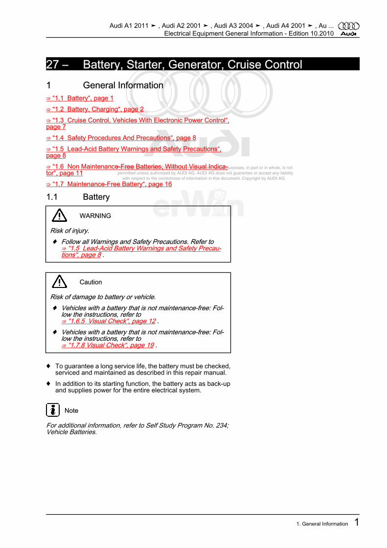
27 – Battery, Starter, Generator, Cruise Control1 General Information⇒ “1.1 Battery“, page 1⇒ “1.2 Battery, Charging“, page 2⇒ “1.3 Cruise Control, Vehicles With Electronic Power Control“,page 7⇒ “1.4 Safety Procedures And Precautions“, page 8⇒ “1.5 Lead-Acid Battery Warnings and Safety Precautions“,page 8⇒ “1.6 Non Maintenance-Free Batteries, Without Visual Indica‐tor“, page 11⇒ “1.7 Maintenance-Free Battery“, page 16
1.1 Battery
WARNING
Risk of injury.♦ Follow all Warnings and Safety Precautions. Refer to
⇒ “1.5 Lead-Acid Battery Warnings and Safety Precau‐tions“, page 8 .
Caution
Risk of damage to battery or vehicle.♦ Vehicles with a battery that is not maintenance-free: Fol‐
low the instructions, refer to⇒ “1.6.5 Visual Check“, page 12 .
♦ Vehicles with a battery that is not maintenance-free: Fol‐low the instructions, refer to⇒ “1.7.8 Visual Check“, page 19 .
♦ To guarantee a long service life, the battery must be checked,serviced and maintained as described in this repair manual.
♦ In addition to its starting function, the battery acts as back-upand supplies power for the entire electrical system.
Note
For additional information, refer to Self Study Program No. 234;Vehicle Batteries.
Audi A1 2011 ➤ , Audi A2 2001 ➤ , Audi A3 2004 ➤ , Audi A4 2001 ➤ , Au ...Electrical Equipment General Information - Edition 10.2010
1. General Information 1
Protected by copyright. Copying for private or commercial purposes, in part or in whole, is not permitted unless authorised by AUDI AG. AUDI AG does not guarantee or accept any liability with respect to the correctness of information in this document. Copyright by AUDI AG.
1.2 Battery, Charging⇒ “1.2.1 Charging The Battery Using VAS 5903 “, page 2⇒ “1.2.2 Exhaustively Discharged Battery“, page 3⇒ “1.2.3 Rapid Charging The Battery, Vehicles Without BatteryMonitoring Control Module J367 Or Energy Management ControlModule J644 “, page 5⇒ “1.2.4 Battery Support Mode With VAS 5903 “, page 6⇒ “1.2.5 Maintenance Charging With Solar Panel VAS 6102 A “,page 7
1.2.1 Charging The Battery Using -VAS 5903-Special tools and workshop equipment required♦ Battery Charger VAS 5903 -VAS 5903-
Note
♦ Battery charger -VAS 5903- charges without current and volt‐age peaks. Batteries can therefore also be charged wheninstalled. When doing this, heed the safety instructions. Thedevices provide an assistance mode in which they providesupply for the circuits.
♦ When working on the electrical system with the electrical con‐sumers temporarily switched on and for “Guided Fault Find‐ing“, the battery must be charged with a battery charger inassistance mode to prevent damage to the battery. Refer to⇒ “1.2.4 Battery Support Mode With VAS 5903 “, page 6 .
♦ For more information regarding the battery charger, refer tothe Operating Instructions that came with the charger.
Procedure• The battery temperature must be at least +10 ℃.
WARNING
Risk of explosion due to open flame, fire and smoking.♦ On non-maintenance-free batteries, the sealing plugs
must be installed tightly.♦ Provide sufficient ventilation.♦ A highly flammable gas forms when batteries are charged.
Never enter rooms where batteries are being charged car‐rying an open flame or while smoking.
♦ Follow the battery charger and battery manufacturer safe‐ty requirements.
♦ Rapid-charging batteries, refer to⇒ “1.2.3 Rapid Charging The Battery, Vehicles WithoutBattery Monitoring Control Module J367 Or Energy Man‐agement Control Module J644 “, page 5 .
Risk of explosion on discharged battery with visual indicator.♦ If the visual indicator has no color or is light yellow, the
battery may not be tested or charged. Jump starting mustnot be used! There is a risk of explosion during testing,charging or jump starting. The battery must be replaced.
Audi A1 2011 ➤ , Audi A2 2001 ➤ , Audi A3 2004 ➤ , Audi A4 2001 ➤ , Au ...Electrical Equipment General Information - Edition 10.2010
2 Rep. Gr.27 - Battery, Starter, Generator, Cruise Control
Protected by copyright. Copying for private or commercial purposes, in part or in whole, is not permitted unless authorised by AUDI AG. AUDI AG does not guarantee or accept any liability with respect to the correctness of information in this document. Copyright by AUDI AG.
Caution
Risk of damaging AGM batteries.♦ AGM batteries must be protected from over voltage.
– Switch off ignition and remove ignition key.– Turn off all electrical consumers.– Perform the battery charging prep work. Refer to⇒ Electrical
Equipment; Rep. Gr. 27 ; Description and Operation .
Note
♦ In vehicles without a Battery monitoring control module -J367-or Energy management control module -J644- , the batterycharger clamps can be connected to the battery terminals orthe positive and ground terminals in the engine compartment.
♦ In vehicles with a Battery monitoring control module -J367- orEnergy management control module -J644- , the black charg‐er clamp “–“ must not be connected to the battery negativeterminal but to the ground terminal in the engine compartmentor the ground pin of the energy management control module-J644- .
– After connecting the charging clamps, connect the batterycharger electrical system connector.
– Switch the charger on.– If necessary, adjust the charge current according to the battery
capacity.• Current should be 10% of the battery capacity (with a 60 Ah
battery, about 6 Ah).– When the battery is fully charged, refer to Battery charger op‐
erating instructions, disconnect the battery charger clamps “+“and “–-“ from the battery.
– Disconnect the battery charger electrical system connector.
1.2.2 Exhaustively Discharged Battery♦ Batteries that have not been used in driving operation for a
long time, for example in stored vehicles, discharge them‐selves.
♦ Batteries are considered to be exhaustively discharged if theno-load voltage drops below 11.6 V. In the case of extendeddowntime under 12.2 volts, the battery is prematurely dam‐aged.
♦ Measure the no-load voltage in vehicles without a Batterymonitoring control module -J367- or Energy management con‐trol module -J644- . Refer to⇒ “4.1.2 Measuring No Load Voltage“, page 32 .
♦ Perform a battery test with a Vehicle Diagnosis Tester if thevehicle has a Battery monitoring control module -J367- or En‐ergy management control module -J644- . Refer to⇒ “4.2.2 Battery Test with Vehicle Diagnosis Tester -“,page 34 .
♦ With exhaustively discharged batteries, the battery acid (mix‐ture of sulfuric acid and water) is mostly water, with a greatlyreduced sulfuric acid content.
Audi A1 2011 ➤ , Audi A2 2001 ➤ , Audi A3 2004 ➤ , Audi A4 2001 ➤ , Au ...Electrical Equipment General Information - Edition 10.2010
1. General Information 3
Protected by copyright. Copying for private or commercial purposes, in part or in whole, is not permitted unless authorised by AUDI AG. AUDI AG does not guarantee or accept any liability with respect to the correctness of information in this document. Copyright by AUDI AG.
♦ Exhaustively discharged batteries become sulfated, i.e. all theplate surfaces of such batteries become hardened. Instead ofbeing transparent, the electrolyte has a slightly milky appear‐ance.
♦ The sulfating process may be reversed if an exhaustively dis‐charged battery is recharged immediately.
♦ If battery is not recharged, plates will continue to harden, andability to accept a charge will diminish. This results in reductionof battery performance.
Procedure• The battery temperature must be at least +10 ℃.
WARNING
Risk of explosion on discharged battery with visual indicator.♦ If the visual indicator has no color or is light yellow, the
battery may not be tested or charged. Jump starting mustnot be used! There is a risk of explosion during testing,charging or jump starting. The battery must be replaced.
Caution
Risk of exhaustively discharged batteries freezing.♦ Exhaustively discharged batteries freeze at low tempera‐
tures, the housing can crack.♦ Batteries that have frozen must no longer be used.
Discharged sulfated batteries must be charged as follows usinga low charging current:– Adjust the charge current to approximately 5% of the battery
capacity, i.e., the charging current for a 60 Ah battery is thenapproximately 3 ampere.
Note
♦ The battery voltage must be at least 0.6 V!♦ The -VAS 5903- battery charger automatically detects ex‐
haustively discharged batteries and carefully starts the charg‐ing procedure with a low charging current. The charge currentis automatically adjusted to the battery charge state.
Caution
Risk of damaging exhaustively discharged batteries.♦ Do not rapid-charge exhaustively discharged batteries.
– Charge the battery. Refer to⇒ “1.2.1 Charging The Battery Using VAS 5903 “, page 2 .
• The charging voltage may be a maximum of 14.4 V.
Audi A1 2011 ➤ , Audi A2 2001 ➤ , Audi A3 2004 ➤ , Audi A4 2001 ➤ , Au ...Electrical Equipment General Information - Edition 10.2010
4 Rep. Gr.27 - Battery, Starter, Generator, Cruise Control
Protected by copyright. Copying for private or commercial purposes, in part or in whole, is not permitted unless authorised by AUDI AG. AUDI AG does not guarantee or accept any liability with respect to the correctness of information in this document. Copyright by AUDI AG.
Note
If the battery must be replaced, follow the disposal regulations,refer to ⇒ page 11 .
1.2.3 Rapid Charging The Battery, VehiclesWithout Battery Monitoring Control Mod‐ule -J367- Or Energy Management Con‐trol Module -J644-
Procedure• The battery temperature must be at least +10 ℃.
WARNING
Risk of explosion due to open flame, fire and smoking.♦ On non-maintenance-free batteries, the sealing plugs
must be installed tightly.♦ Provide sufficient ventilation.♦ A highly flammable gas forms when batteries are charged.
Never enter rooms where batteries are being charged car‐rying an open flame or while smoking.
♦ Follow the battery charger and battery manufacturer safe‐ty requirements.
Risk of explosion on discharged battery with visual indicator.♦ If the visual indicator has no color or is light yellow, the
battery may not be tested or charged. Jump starting mustnot be used! There is a risk of explosion during testing,charging or jump starting. The battery must be replaced.
Caution
Risk of damaging the battery and vehicle electronic compo‐nents.♦ Do not rapid charge AGM batteries.♦ Do not rapid charge batteries in vehicles with a battery
monitoring control module -J367- or energy managementcontrol module -J644- .
♦ Do not rapid-charge exhaustively discharged batteries.♦ Rapid-charging of batteries should only be performed in
exceptional circumstances (for example, jump starting)since rapid charging may cause damage.
♦ Battery must not be connected to vehicle electrical systemwhen performing rapid charging. Disconnect the positiveand negative cables from the terminals. Refer to⇒ Elec‐trical system; Rep. Gr. 27 ; Removal and Installation .
♦ The maximum charging voltage is 14.8 volt.
Audi A1 2011 ➤ , Audi A2 2001 ➤ , Audi A3 2004 ➤ , Audi A4 2001 ➤ , Au ...Electrical Equipment General Information - Edition 10.2010
1. General Information 5
Protected by copyright. Copying for private or commercial purposes, in part or in whole, is not permitted unless authorised by AUDI AG. AUDI AG does not guarantee or accept any liability with respect to the correctness of information in this document. Copyright by AUDI AG.
Note
If the battery must be replaced, follow the disposal regulations,refer to ⇒ page 11 .
1.2.4 Battery Support Mode With -VAS 5903-Special tools and workshop equipment required♦ Battery Charger VAS 5903 -VAS 5903-The battery support mode is needed, for example, when takingbreaks from fault finding in the workshop or when replacing thebattery.Procedure
Note
♦ For more information regarding the battery charger, refer tothe Operating Instructions that came with the charger.
♦ In the following, the battery support mode is described as anexample of -VAS 5900- .
– Switch off ignition and remove ignition key.– Turn off all electrical consumers.– Connect the battery charger electrical system connector -VAS
5900- .• The last selected operating mode appears on the display.– Press theStart/Stop button for approximately 5 seconds.
• The menu selection “Charging severely discharged batteries/Support mode“ is activated.
– Press the ↑ button or the ↓ button in order to adjust the vehicleelectrical system.
Note
If no button is pressed within 5 seconds, the -VAS 5900- switchesback to the main menu.
– Confirm selected battery voltage with Start/Stop button.
– Perform the battery support mode prep work. Refer to ⇒ Elec‐trical Equipment; Rep. Gr. 27 ; Description and Operation .
• The charging clips are checked for connection to correct poles.
Caution
Risk of damaging the -VAS 5900- and vehicle electronic com‐ponents.♦ If the battery terminal clamps are connected incorrectly,
the Start/Stop button must not be pressed.
– Confirm charging clips are connected to correct poles viaStart/Stop .
Audi A1 2011 ➤ , Audi A2 2001 ➤ , Audi A3 2004 ➤ , Audi A4 2001 ➤ , Au ...Electrical Equipment General Information - Edition 10.2010
6 Rep. Gr.27 - Battery, Starter, Generator, Cruise Control

Protected by copyright. Copying for private or commercial purposes, in part or in whole, is not permitted unless authorised by AUDI AG. AUDI AG does not guarantee or accept any liability with respect to the correctness of information in this document. Copyright by AUDI AG.
• The -VAS 5900- starts the assistance mode.– To end support mode, press the Start/Stop button.
– Disconnect the battery charger electrical system connector.
1.2.5 Maintenance Charging With Solar Panel-VAS 6102 A-
Special tools and workshop equipment required♦ Solar Panel -VAS 6102 A-♦ The solar panel -VAS 6102 A- supports the vehicle electrical
system and prevents the battery from self-discharging.♦ All chargeable batteries can be charged by the solar panel.♦ The solar panel is connected at the diagnostic connection in‐
side the vehicle. A battery charger may not be connected tothe diagnostic connection.
Procedure
Note
For more information regarding the solar panel -VAS 6102 A- re‐fer to the Owner's Manual that came with -VAS 6102 A- .
– Secure the solar panel -VAS 6102 A- on the interior rearviewmirror -1-.
– Lay the bottom of the solar panel on the instrument panel-2-.
Note
The whole solar panel -VAS 6102 A- may not lie on the instrumentpanel. Only the bottom edge may be used for support. If it touchescompletely, the color of the instrument panel could change.
– Pull the securing string together so that the solar panel is closeto the windshield.
– Connect the solar panel to the diagnostic connection -arrow-.• The green LED in the solar panel frame displays the function:
The brighter the LED, the higher the charging current. It is notpossible to overcharge the battery due to the integrated elec‐tronics.
1.3 Cruise Control, Vehicles With ElectronicPower Control
♦ The function of the Cruise Control System (CCS) is controlledby the Engine Control Module on vehicles with ElectronicPower Control (EPC).
Audi A1 2011 ➤ , Audi A2 2001 ➤ , Audi A3 2004 ➤ , Audi A4 2001 ➤ , Au ...Electrical Equipment General Information - Edition 10.2010
1. General Information 7
Protected by copyright. Copying for private or commercial purposes, in part or in whole, is not permitted unless authorised by AUDI AG. AUDI AG does not guarantee or accept any liability with respect to the correctness of information in this document. Copyright by AUDI AG.
♦ Malfunctions in relation to CCS are sent via the Engine ControlModule (ECM).
– For trouble shooting, use a Vehicle Diagnosis, Testing & In‐formation System -VAS5051B- in the “Guided Fault Finding“function.
1.4 Safety Procedures And PrecautionsBefore beginning work, the mechanics must be acquainted withthe possible risks when handling batteries.
Caution
Personnel instructed in protection, such as a trainee or ap‐prentice, may only perform work on vehicle batteries under thesupervision of technical personnel such as a master automo‐tive mechanic or a master automotive electrician.
1.5 Lead-Acid Battery Warnings and SafetyPrecautions
Recognizing and Preventing RisksIt is dangerous to handle batteries. These risks can be avoidedby following the warnings on the battery, in the operating instruc‐tions, and in the repair manual.
Audi A1 2011 ➤ , Audi A2 2001 ➤ , Audi A3 2004 ➤ , Audi A4 2001 ➤ , Au ...Electrical Equipment General Information - Edition 10.2010
8 Rep. Gr.27 - Battery, Starter, Generator, Cruise Control
Protected by copyright. Copying for private or commercial purposes, in part or in whole, is not permitted unless authorised by AUDI AG. AUDI AG does not guarantee or accept any liability with respect to the correctness of information in this document. Copyright by AUDI AG.
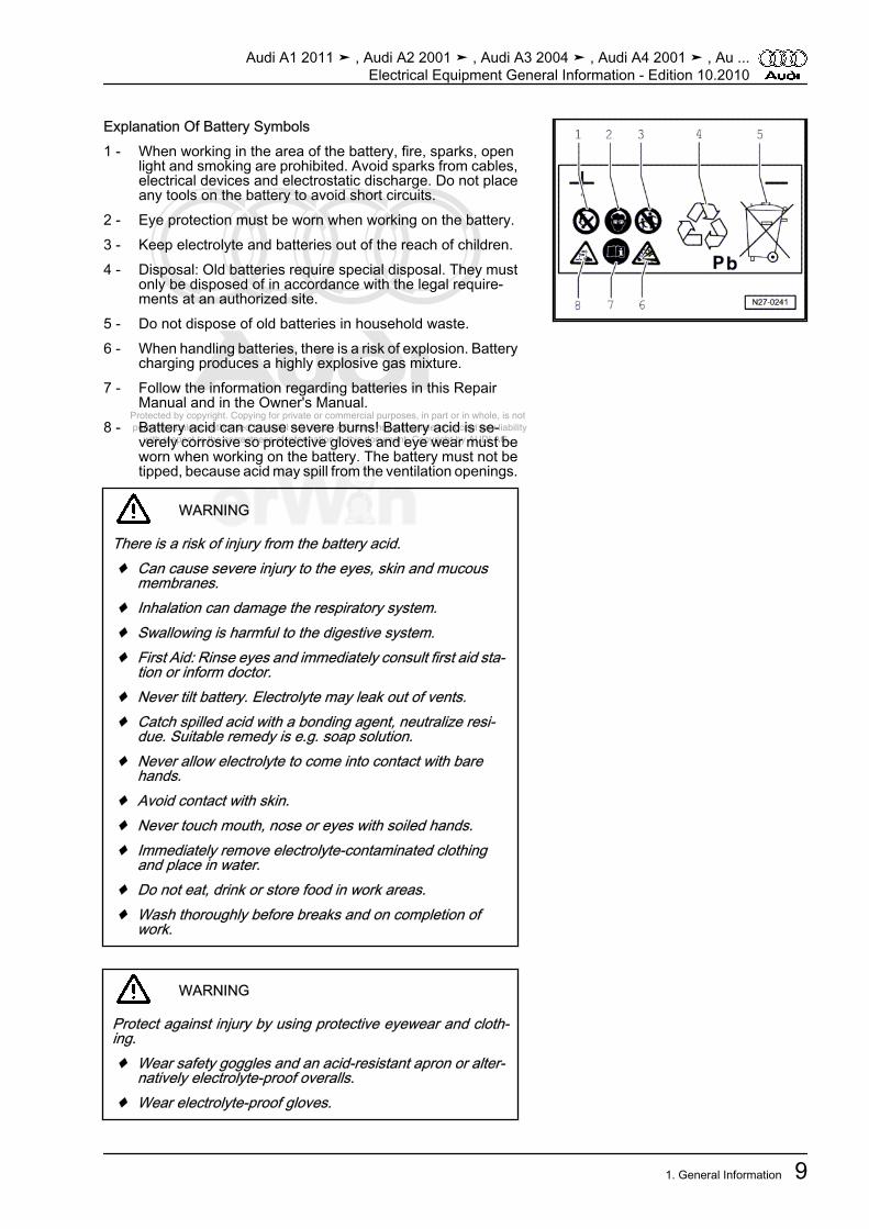
Explanation Of Battery Symbols1 - When working in the area of the battery, fire, sparks, open
light and smoking are prohibited. Avoid sparks from cables,electrical devices and electrostatic discharge. Do not placeany tools on the battery to avoid short circuits.
2 - Eye protection must be worn when working on the battery.3 - Keep electrolyte and batteries out of the reach of children.4 - Disposal: Old batteries require special disposal. They must
only be disposed of in accordance with the legal require‐ments at an authorized site.
5 - Do not dispose of old batteries in household waste.6 - When handling batteries, there is a risk of explosion. Battery
charging produces a highly explosive gas mixture.7 - Follow the information regarding batteries in this Repair
Manual and in the Owner's Manual.8 - Battery acid can cause severe burns! Battery acid is se‐
verely corrosive so protective gloves and eye wear must beworn when working on the battery. The battery must not betipped, because acid may spill from the ventilation openings.
WARNING
There is a risk of injury from the battery acid.♦ Can cause severe injury to the eyes, skin and mucous
membranes.♦ Inhalation can damage the respiratory system.♦ Swallowing is harmful to the digestive system.♦ First Aid: Rinse eyes and immediately consult first aid sta‐
tion or inform doctor.♦ Never tilt battery. Electrolyte may leak out of vents.♦ Catch spilled acid with a bonding agent, neutralize resi‐
due. Suitable remedy is e.g. soap solution.♦ Never allow electrolyte to come into contact with bare
hands.♦ Avoid contact with skin.♦ Never touch mouth, nose or eyes with soiled hands.♦ Immediately remove electrolyte-contaminated clothing
and place in water.♦ Do not eat, drink or store food in work areas.♦ Wash thoroughly before breaks and on completion of
work.
WARNING
Protect against injury by using protective eyewear and cloth‐ing.♦ Wear safety goggles and an acid-resistant apron or alter‐
natively electrolyte-proof overalls.♦ Wear electrolyte-proof gloves.
Audi A1 2011 ➤ , Audi A2 2001 ➤ , Audi A3 2004 ➤ , Audi A4 2001 ➤ , Au ...Electrical Equipment General Information - Edition 10.2010
1. General Information 9

Protected by copyright. Copying for private or commercial purposes, in part or in whole, is not permitted unless authorised by AUDI AG. AUDI AG does not guarantee or accept any liability with respect to the correctness of information in this document. Copyright by AUDI AG.
WARNING
Risk of explosion due to the explosive gas that forms duringbattery charging.♦ The gas resulting from charging and partially when resting
after charging is explosive. In extreme cases, if battery ishandled inappropriately, the emitted gases may cause thebattery to explode.
♦ Smoking, open flame, fire and sparks (from sanding, weld‐ing or separating work) are prohibited when working nearthe battery.
♦ Avoid short circuits when working with electrical wires anddevices. Do not place any tools on the battery.
♦ To prevent sparks from forming due to electrostatic dis‐charge, always touch the vehicle body before touching thebattery.
WARNING
Protect against explosion.♦ On batteries with a visual indicator, the battery must not
be tested or charged if the indicator has no color or is lightyellow. Jump starting must not be used! There is a risk ofexplosion during testing, charging or jump starting. Thebattery must be replaced.
♦ Used batteries (lengthy period of use over 6 months) mustbe treated with an anti-static spray (currently “NeostaticAntistatikum HB 155“) prior to handling.
♦ In the case of batteries that are not maintenance-free, thesealing plugs must be securely installed when chargingthe battery.
♦ Charging of removed batteries is only permitted while ex‐tracting fumes in ventilated cabinets.
♦ After charging, the battery must be kept in the area whereit was charged for an appropriate time period.
♦ Only perform battery procedures in suitable and well-ven‐tilated rooms.
♦ Batteries are always to be transported in conductive metalcontainers.
♦ Do not use any materials that can be charged electrostat‐ically.
WARNING
Risk of damage to the vehicle.♦ Safety-related vehicle components could be damaged by
acid burns and corrosion due to escaping battery acid.
Audi A1 2011 ➤ , Audi A2 2001 ➤ , Audi A3 2004 ➤ , Audi A4 2001 ➤ , Au ...Electrical Equipment General Information - Edition 10.2010
10 Rep. Gr.27 - Battery, Starter, Generator, Cruise Control

Protected by copyright. Copying for private or commercial purposes, in part or in whole, is not permitted unless authorised by AUDI AG. AUDI AG does not guarantee or accept any liability with respect to the correctness of information in this document. Copyright by AUDI AG.
WARNING
Pollution risk.♦ Old batteries require special disposal. They contain poi‐
sonous lead (Pb) and sulfuric acid.♦ Follow disposal requirements, only dispose of used bat‐
teries in suitable containers at an authorized collectionsite.
1.6 Non Maintenance-Free Batteries, With‐out Visual Indicator
⇒ “1.6.1 General Information“, page 11⇒ “1.6.2 Central Venting System“, page 11⇒ “1.6.3 Battery Post/Terminal“, page 12⇒ “1.6.4 Testing“, page 12⇒ “1.6.5 Visual Check“, page 12⇒ “1.6.6 Electrolyte Level, Checking“, page 13⇒ “1.6.7 Acid Density, Measuring“, page 14
1.6.1 General InformationLead acid batteries that are not maintenance-free are filled withfluid electrolyte (wet battery). They have sealing plugs.
WARNING
Risk of injury from direct exposure to battery acid!♦ Observe warning notes and safety precautions. Refer to
⇒ page 9 .Risk of explosion due to the explosive gas that forms duringbattery charging.♦ Observe warning notes and safety precautions. Refer to
⇒ page 10 .
1.6.2 Central Venting SystemTo prevent the gas resulting from battery charging from causingdamage or putting health at risk, the gas is discharged centrallythrough an opening on the top cover side of the battery.– Make sure the central venting hose or tube is always secured
on the battery.– Make sure the central venting hose or tube is not pinched. Only
then can battery be properly vented.
Audi A1 2011 ➤ , Audi A2 2001 ➤ , Audi A3 2004 ➤ , Audi A4 2001 ➤ , Au ...Electrical Equipment General Information - Edition 10.2010
1. General Information 11

Protected by copyright. Copying for private or commercial purposes, in part or in whole, is not permitted unless authorised by AUDI AG. AUDI AG does not guarantee or accept any liability with respect to the correctness of information in this document. Copyright by AUDI AG.
Note
Newer generation batteries have a fine mesh flame trap at thecentral venting exit point. The flame trap is a round fiberglass matapproximately 15 mm wide and 2 mm thick that works like a valve.On the one hand, it allows the gas formed during battery chargingto flow out and on the other hand, prevents the explosive gas inthe battery from igniting.
1.6.3 Battery Post/TerminalTo prevent damage to the battery terminals and battery housing,observe the following:♦ Do not put any grease on the battery terminals.♦ Battery terminal clamps -arrows- must only be installed by
hand without applying force.♦ Install battery terminal clamps so the terminal is flush with the
clamp or protrudes out of it.♦ Battery terminal clamps and auxiliary clamps, tightening spec‐
ification, refer to⇒ Electrical Equipment; Rep. Gr. 27 ; Spec‐ifications .
♦ After tightening the battery terminal clamps to the specifiedtorque, the threaded connections must not be tightened again.
1.6.4 Testing
WARNING
Risk of injury and explosion!♦ Follow all Warnings and Safety Precautions. Refer to
⇒ “1.5 Lead-Acid Battery Warnings and Safety Precau‐tions“, page 8 .
Perform Battery Checks In The Following Sequence1. Visual check. Refer to ⇒ “1.6.5 Visual Check“, page 12 .2. Check the battery electrolyte level. Refer to
⇒ “1.6.6 Electrolyte Level, Checking“, page 13 .3. Battery testing with the Battery tester -VAS 6161- , refer to
⇒ “4.1.1 Battery Test Using Battery Tester VAS 6161 “,page 28 or measure the battery acid density, refer to⇒ “1.6.7 Acid Density, Measuring“, page 14 .
4. Additional procedure depends on the result of the batterytest with the battery tester.
1.6.5 Visual Check– Before performing extensive measurements, inspect visually.♦ External battery condition;♦ Battery connections;♦ Secure battery seating.
Audi A1 2011 ➤ , Audi A2 2001 ➤ , Audi A3 2004 ➤ , Audi A4 2001 ➤ , Au ...Electrical Equipment General Information - Edition 10.2010
12 Rep. Gr.27 - Battery, Starter, Generator, Cruise Control
Protected by copyright. Copying for private or commercial purposes, in part or in whole, is not permitted unless authorised by AUDI AG. AUDI AG does not guarantee or accept any liability with respect to the correctness of information in this document. Copyright by AUDI AG.
Caution
Risk of explosion, inadequate crash safety, risk of corrosion,shortened service life.♦ A loose battery retaining bracket can damage the battery
housing and allow battery acid to leak.♦ A battery that is mounted incorrectly can sustain vibration
damage resulting in damage to the battery plates.♦ Tighten retaining bracket bolt; tightening specification, re‐
fer to⇒ Electrical Equipment; Rep. Gr. 27 ; Specifications .Risk of malfunction in the electrical system or wiring burn.♦ The wiring connection contact is not guaranteed if the bat‐
tery terminals are damaged or the battery terminal clampsare loose. Check the condition of the battery terminals;battery terminal clamp and auxiliary clamp tighteningspecification. Refer to⇒ Electrical Equipment; Rep. Gr. 27 ; Specifications .
♦ Risk of corrosion due to leaking battery acid.♦ To ensure that the various battery connection systems are
free of leaks, the battery's original sealing plugs must beinstalled in the battery openings. Only replace missing ordamaged sealing plugs with the same type of originalplugs.
♦ The sealing plugs must be equipped with an O-ring.
1.6.6 Electrolyte Level, CheckingProcedureMaintaining the correct electrolyte level in the battery is an im‐portant factor affecting the length of the battery's service life.
WARNING
Risk of injury from direct exposure to battery acid.♦ Follow accident prevention regulations when working with
battery acid. Refer to ⇒ page 9 .♦ Wear protective eyewear and clothing. Refer to
⇒ page 9 .Risk of explosion due to open flame, fire and smoking.♦ Only illuminate the inside of the battery housing with a
flashlight.♦ Never illuminate the inside of the battery housing with an
open flame.♦ Never handle open flame or burning cigarettes near bat‐
teries.
– If the “Min“ and “Max“ marking on the outside of the batterycan be seen, simply inspect by sight.
• The electrolyte level must be above the “Min“ marking but mustonly go as high as the “Max“ marking.
– If it is difficult to see the “Min“ and “Max“ markings on the out‐side of the battery or they cannot be seen because the batteryhousing is opaque, remove the sealing plugs.
Audi A1 2011 ➤ , Audi A2 2001 ➤ , Audi A3 2004 ➤ , Audi A4 2001 ➤ , Au ...Electrical Equipment General Information - Edition 10.2010
1. General Information 13
Protected by copyright. Copying for private or commercial purposes, in part or in whole, is not permitted unless authorised by AUDI AG. AUDI AG does not guarantee or accept any liability with respect to the correctness of information in this document. Copyright by AUDI AG.
– Check electrolyte level by visually checking the inside of thebattery.
• The electrolyte level must coincide with the internal level mark(plastic web). This corresponds to the outer “Max“ marking.
Caution
Risk of corrosion due to leaking battery acid.♦ To ensure that the various battery connection systems are
free of leaks, the battery's original sealing plugs must beinstalled in the battery openings. Only replace missing ordamaged sealing plugs with the same type of originalplugs.
♦ The sealing plugs must be equipped with an O-ring.♦ If the acid level is too low, the battery must be replaced.
Do not add distilled water.
– Screw in the sealing plugs of battery cells.
1.6.7 Acid Density, MeasuringSpecial tools and workshop equipment required♦ Refractometer -T10007- or♦ Commercially Available HydrometerProcedureIn conjunction with the battery test using the Battery tester -VAS 6161- , refer to⇒ “4.1.1 Battery Test Using Battery Tester VAS 6161 “,page 28 , the acid density test provides information about thecondition of the battery.• The temperature of the battery acid must be at least +10° C
(50° F).
WARNING
Risk of injury from direct exposure to battery acid.♦ Follow accident prevention regulations when working with
battery acid. Refer to ⇒ page 9 .♦ Wear protective eyewear and clothing. Refer to
⇒ page 9 .
Note
Specific density of the electrolyte can be checked immediatelyafter charging battery.
– Remove all sealing plugs of battery cells.
Audi A1 2011 ➤ , Audi A2 2001 ➤ , Audi A3 2004 ➤ , Audi A4 2001 ➤ , Au ...Electrical Equipment General Information - Edition 10.2010
14 Rep. Gr.27 - Battery, Starter, Generator, Cruise Control

Protected by copyright. Copying for private or commercial purposes, in part or in whole, is not permitted unless authorised by AUDI AG. AUDI AG does not guarantee or accept any liability with respect to the correctness of information in this document. Copyright by AUDI AG.
– Dip hydrometer into battery cell and siphon off enough elec‐trolyte until the float floats freely in electrolyte.
♦ The higher the specific weight of the siphoned battery acid, thehigher the float will float.
♦ The acid density of the electrolyte can be read off in kg/dm3on the hydrometer scale (specific density of the battery acid).
– Compare hydrometer reading to values given in table.
Charge condi‐tion
Acid Density in kg/dm3
In Normal Climates In The TropicsDischarged 1.12 1.08Partial charge 1.20 1.16Fully charged 1.28 1.23
Specific acid density must be at least 1.24 kg/dm3 in moderateclimate zones. If the acid density in all battery cells is too low:– Charge battery and repeat acid density test.
Example 1
Battery cell 1 2 3 4 5 6Acid density per battery cell in kg/dm3
1.24 1.25 1.25 1.10 1) 1.24 1.25
• 1) The acid density in battery cell 4 is too low (deviation greater than 0.03 kg/dm3).
Example 2
Battery cell 1 2 3 4 5 6Acid density per battery cell in kg/dm3
1.26 1.26 1.25 1.14 1) 1.18 1) 1.24
• 1) The acid density in battery cells 4 and 5 is too low (deviation greater than 0.03 kg/dm3).
– If the specified values are not reached, replace the battery.
Note
The measured values for the specific density of the individualbattery cells must not deviate by more than 0.03 kg/dm3, other‐wise the battery should be replaced.
Caution
Risk due to leaking battery acid.♦ To ensure that the various battery connection systems are
free of leaks, the battery's original sealing plugs must beinstalled in the battery openings. Only replace missing ordamaged sealing plugs with the same type of originalplugs.
♦ The sealing plugs must be equipped with an O-ring.
Audi A1 2011 ➤ , Audi A2 2001 ➤ , Audi A3 2004 ➤ , Audi A4 2001 ➤ , Au ...Electrical Equipment General Information - Edition 10.2010
1. General Information 15
Protected by copyright. Copying for private or commercial purposes, in part or in whole, is not permitted unless authorised by AUDI AG. AUDI AG does not guarantee or accept any liability with respect to the correctness of information in this document. Copyright by AUDI AG.
– If the specified values are reached, reinstall the sealing plugson the battery cells.
Note
If the battery must be replaced, follow the disposal regulations.Refer to ⇒ page 11 .
1.7 Maintenance-Free Battery⇒ “1.7.1 General Information“, page 16⇒ “1.7.2 Battery With Visual Indicator “, page 16⇒ “1.7.3 Battery with Visual Indicator, Checking“, page 17⇒ “1.7.4 Absorbent Glass Mat (AGM) Battery, Without Visual In‐dicator“, page 17⇒ “1.7.5 Absorbent Glass Mat (AGM) Battery, Checking“,page 18⇒ “1.7.6 Central Venting System“, page 18⇒ “1.7.7 Battery Post/Terminal“, page 18⇒ “1.7.8 Visual Check“, page 19⇒ “1.7.9 Electrolyte Level Color, Checking“, page 20⇒ “1.7.10 Electrolyte Level, Checking“, page 20
1.7.1 General InformationOnly maintenance-free batteries conforming to standards“TL82506“ (as of December 1997) and “VW75073“ (as of August2001) may be installed.
WARNING
Risk of injury due to contact with battery acid!♦ Observe warning notes and safety precautions. Refer to
⇒ page 9 .Risk of explosion due to the explosive gas that forms duringbattery charging.♦ Observe warning notes and safety precautions. Refer to
⇒ page 10 .
1.7.2 Battery With Visual IndicatorLead acid batteries with visual indicators are filled with fluid elec‐trolyte (wet battery). They do not have sealing plugs for filling withdistilled water.
Note
♦ If batteries with a visual indicator are equipped with sealingplugs for production reasons, the plugs are covered with plas‐tic sheeting.
♦ The covering must not be removed and distilled water mustnot be added.
♦ Only perform a visual inspection.
Audi A1 2011 ➤ , Audi A2 2001 ➤ , Audi A3 2004 ➤ , Audi A4 2001 ➤ , Au ...Electrical Equipment General Information - Edition 10.2010
16 Rep. Gr.27 - Battery, Starter, Generator, Cruise Control
Protected by copyright. Copying for private or commercial purposes, in part or in whole, is not permitted unless authorised by AUDI AG. AUDI AG does not guarantee or accept any liability with respect to the correctness of information in this document. Copyright by AUDI AG.
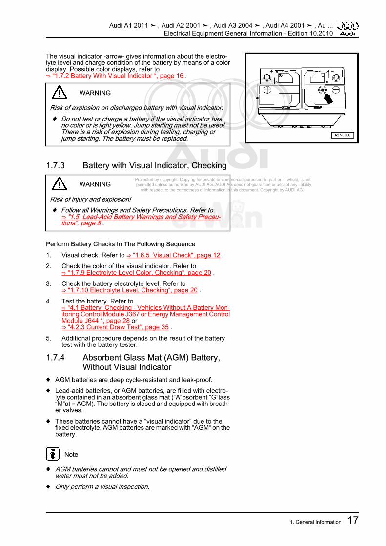
The visual indicator -arrow- gives information about the electro‐lyte level and charge condition of the battery by means of a colordisplay. Possible color displays, refer to⇒ “1.7.2 Battery With Visual Indicator “, page 16 .
WARNING
Risk of explosion on discharged battery with visual indicator.♦ Do not test or charge a battery if the visual indicator has
no color or is light yellow. Jump starting must not be used!There is a risk of explosion during testing, charging orjump starting. The battery must be replaced.
1.7.3 Battery with Visual Indicator, Checking
WARNING
Risk of injury and explosion!♦ Follow all Warnings and Safety Precautions. Refer to
⇒ “1.5 Lead-Acid Battery Warnings and Safety Precau‐tions“, page 8 .
Perform Battery Checks In The Following Sequence1. Visual check. Refer to ⇒ “1.6.5 Visual Check“, page 12 .2. Check the color of the visual indicator. Refer to
⇒ “1.7.9 Electrolyte Level Color, Checking“, page 20 .3. Check the battery electrolyte level. Refer to
⇒ “1.7.10 Electrolyte Level, Checking“, page 20 .4. Test the battery. Refer to
⇒ “4.1 Battery, Checking - Vehicles Without A Battery Mon‐itoring Control Module J367 or Energy Management ControlModule J644 “, page 28 or⇒ “4.2.3 Current Draw Test“, page 35 .
5. Additional procedure depends on the result of the batterytest with the battery tester.
1.7.4 Absorbent Glass Mat (AGM) Battery,Without Visual Indicator
♦ AGM batteries are deep cycle-resistant and leak-proof.♦ Lead-acid batteries, or AGM batteries, are filled with electro‐
lyte contained in an absorbent glass mat (“A“bsorbent “G“lass“M“at = AGM). The battery is closed and equipped with breath‐er valves.
♦ These batteries cannot have a “visual indicator“ due to thefixed electrolyte. AGM batteries are marked with “AGM“ on thebattery.
Note
♦ AGM batteries cannot and must not be opened and distilledwater must not be added.
♦ Only perform a visual inspection.
Audi A1 2011 ➤ , Audi A2 2001 ➤ , Audi A3 2004 ➤ , Audi A4 2001 ➤ , Au ...Electrical Equipment General Information - Edition 10.2010
1. General Information 17

Protected by copyright. Copying for private or commercial purposes, in part or in whole, is not permitted unless authorised by AUDI AG. AUDI AG does not guarantee or accept any liability with respect to the correctness of information in this document. Copyright by AUDI AG.
Caution
Crash safety is inadequate if the incorrect battery is installed.♦ If the vehicle was originally equipped with an AGM battery,
another AGM battery must be installed when replacing.
1.7.5 Absorbent Glass Mat (AGM) Battery,Checking
WARNING
Risk of injury and explosion!♦ Follow all Warnings and Safety Precautions. Refer to
⇒ “1.5 Lead-Acid Battery Warnings and Safety Precau‐tions“, page 8 .
Perform Battery Checks In The Following Sequence1. Visual check. Refer to ⇒ “1.6.5 Visual Check“, page 12 .2. Test the battery. Refer to
⇒ “4.1 Battery, Checking - Vehicles Without A Battery Mon‐itoring Control Module J367 or Energy Management ControlModule J644 “, page 28 or⇒ “4.2.3 Current Draw Test“, page 35 .
3. Additional procedure depends on the result of the batterytest with the battery tester.
1.7.6 Central Venting SystemTo prevent the gas that forms in the engine compartment or ve‐hicle interior during battery charging from causing damage orposing a threat to health, the gas is discharged centrally throughan opening on the top cover side of the battery.– Make sure the central venting hose or tube is always secured
on the battery.– Make sure the central venting hose or tube is not pinched. Only
then can battery be properly vented.
Note
Newer generation batteries have a fine mesh flame trap at thecentral venting exit point. The flame trap is a round fiberglass matapproximately 15 mm wide and 2 mm thick that works like a valve.On the one hand, it allows the gas formed during battery chargingto flow out and on the other hand, prevents the explosive gas inthe battery from igniting.
1.7.7 Battery Post/TerminalTo prevent damage to the battery terminals and battery housing,observe the following:
Audi A1 2011 ➤ , Audi A2 2001 ➤ , Audi A3 2004 ➤ , Audi A4 2001 ➤ , Au ...Electrical Equipment General Information - Edition 10.2010
18 Rep. Gr.27 - Battery, Starter, Generator, Cruise Control

Protected by copyright. Copying for private or commercial purposes, in part or in whole, is not permitted unless authorised by AUDI AG. AUDI AG does not guarantee or accept any liability with respect to the correctness of information in this document. Copyright by AUDI AG.
♦ Do not put any grease on the battery terminals.♦ Battery terminal clamps -arrows- must only be installed by
hand without applying force.♦ Install battery terminal clamps so the terminal is flush with the
clamp or protrudes out of it.♦ Battery terminal clamps and auxiliary clamps, tightening spec‐
ification. Refer to⇒ Electrical Equipment; Rep. Gr. 27 ;Specifications .
♦ After tightening the battery terminal clamps to the specifiedtorque, the threaded connections must not be tightened again.
1.7.8 Visual Check– Before performing extensive measurements, inspect visually.♦ External battery condition;♦ Battery connections;♦ Secure battery seating.
Caution
Risk of explosion, inadequate crash safety, risk of corrosion,shortened service life.♦ A loose battery retaining bracket can damage the battery
housing and allow battery acid to leak.♦ A battery that is mounted incorrectly can sustain vibration
damage resulting in damage to the battery plates.♦ Tighten retaining bracket bolt; tightening specification, re‐
fer to⇒ Electrical Equipment; Rep. Gr. 27 ; Specifications .Risk of malfunction in the electrical system or wiring burn.♦ The wiring connection contact is not guaranteed if the bat‐
tery terminals are damaged or the battery terminal clampsare loose. Check the condition of the battery terminals;battery terminal clamp and auxiliary clamp tighteningspecification. Refer to⇒ Electrical Equipment; Rep. Gr. 27 ; Specifications .
Audi A1 2011 ➤ , Audi A2 2001 ➤ , Audi A3 2004 ➤ , Audi A4 2001 ➤ , Au ...Electrical Equipment General Information - Edition 10.2010
1. General Information 19

Protected by copyright. Copying for private or commercial purposes, in part or in whole, is not permitted unless authorised by AUDI AG. AUDI AG does not guarantee or accept any liability with respect to the correctness of information in this document. Copyright by AUDI AG.
1.7.9 Electrolyte Level Color, CheckingProcedure
Note
Because the visual indicator is located in only one battery cell, thebattery acid level is only checked for that cell.
– To obtain an accurate reading, gently tap the visual indicator-arrow- with a screwdriver handle.
Note
When charging the battery and while driving, air bubbles can formbelow the visual indicator and result in an incorrect color display.Tapping releases the air bubbles under the visual indicator.
– Check the battery acid level using the color indicator. Two dif‐ferent displays are possible:
Color Indication Battery Charge ConditionBlack or green • Battery acid level OK
Colorless or brightyellow
• Battery acid level too low. Risk of explo‐sion, the battery must not be tested orcharged.
WARNING
Risk of explosion on discharged battery with visual indicator.♦ If the visual indicator has no color or is light yellow, the
battery may not be tested or charged. Jump starting mustnot be used! There is a risk of explosion during testing,charging or jump starting. The battery must be replaced.
Note
If the battery must be replaced, follow the disposal regulations.Refer to ⇒ page 11 .
1.7.10 Electrolyte Level, CheckingProcedureMaintaining the correct electrolyte level in the battery is an im‐portant factor affecting the length of the battery's service life.
Audi A1 2011 ➤ , Audi A2 2001 ➤ , Audi A3 2004 ➤ , Audi A4 2001 ➤ , Au ...Electrical Equipment General Information - Edition 10.2010
20 Rep. Gr.27 - Battery, Starter, Generator, Cruise Control
Protected by copyright. Copying for private or commercial purposes, in part or in whole, is not permitted unless authorised by AUDI AG. AUDI AG does not guarantee or accept any liability with respect to the correctness of information in this document. Copyright by AUDI AG.
WARNING
Risk of injury due to contact with battery acid.♦ Follow accident prevention regulations when working with
battery acid. Refer to ⇒ page 9 .♦ Wear protective eyewear and clothing. Refer to
⇒ page 9 .♦ If the electrolyte level is too low, the battery must be re‐
placed. It must not be opened and distilled water must notbe added.
Risk of explosion due to open flame, fire and smoking.♦ Never handle open flame or burning cigarettes near bat‐
teries.
– If the “Min“ and “Max“ marking on the outside of the batterycan be seen, simply inspect by sight.
• The electrolyte level must be above the “Min“ marking but mustonly go as high as the “Max“ marking.
Audi A1 2011 ➤ , Audi A2 2001 ➤ , Audi A3 2004 ➤ , Audi A4 2001 ➤ , Au ...Electrical Equipment General Information - Edition 10.2010
1. General Information 21

Protected by copyright. Copying for private or commercial purposes, in part or in whole, is not permitted unless authorised by AUDI AG. AUDI AG does not guarantee or accept any liability with respect to the correctness of information in this document. Copyright by AUDI AG.
2 Description and Operation⇒ “2.1 Bosch Generator Overview, Through 2000“, page 22⇒ “2.2 Bosch Generator Overview, From 2001“, page 23⇒ “2.3 Bosch Generator Overview, From 2007“, page 24⇒ “2.4 Valeo Generator Overview, Through 2000“, page 25⇒ “2.5 Valeo Generator Overview, From 2001“, page 26
2.1 Bosch Generator Overview, Through 2000
1 - Bolts❑ 1 Nm
2 - Cover❑ With 3 retaining tabs
3 - Bolts❑ 2 Nm
4 - Voltage Regulator❑ Removing:– Remove bolts -item 1-
and remove protectivecap -item 2-.
– Remove the bolts-item 3- and remove thevoltage regulator.
❑ Carbon brush wear limit:5 mm
5 - Generator
Audi A1 2011 ➤ , Audi A2 2001 ➤ , Audi A3 2004 ➤ , Audi A4 2001 ➤ , Au ...Electrical Equipment General Information - Edition 10.2010
22 Rep. Gr.27 - Battery, Starter, Generator, Cruise Control

Protected by copyright. Copying for private or commercial purposes, in part or in whole, is not permitted unless authorised by AUDI AG. AUDI AG does not guarantee or accept any liability with respect to the correctness of information in this document. Copyright by AUDI AG.
2.2 Bosch Generator Overview, From 2001
Note
The generators were implemented as a running change.
1 - Generator2 - Voltage Regulator
❑ Removing and instal‐ling, refer to⇒ “5.1 Voltage Regula‐tor, Bosch Generator,From 2001“, page 40 .
❑ Carbon brushes, check‐ing, refer to⇒ “4.4 Carbon Brush,Checking, Bosch Gen‐erators From 2001“,page 38 .
3 - Screw❑ 2.5 Nm
4 - Cover5 - Nut
❑ 12 Nm6 - Nut
❑ 30 Nm7 - Screw
❑ 3 Nm8 - Screw
❑ 1.5 Nm
Audi A1 2011 ➤ , Audi A2 2001 ➤ , Audi A3 2004 ➤ , Audi A4 2001 ➤ , Au ...Electrical Equipment General Information - Edition 10.2010
2. Description and Operation 23

Protected by copyright. Copying for private or commercial purposes, in part or in whole, is not permitted unless authorised by AUDI AG. AUDI AG does not guarantee or accept any liability with respect to the correctness of information in this document. Copyright by AUDI AG.
2.3 Bosch Generator Overview, From 2007
Note
The new generators are installed as a running change.
1 - Nut❑ 65 Nm
2 - Ribbed Belt Pulley3 - Generator4 - Voltage Regulator
❑ Removing and instal‐ling, refer to⇒ “5.2 Voltage Regula‐tor, Bosch Generator,From 2007“, page 40 .
❑ Carbon brushes, check‐ing, refer to⇒ “4.4 Carbon Brush,Checking, Bosch Gen‐erators From 2001“,page 38 .
5 - Screw❑ 1.5 Nm
6 - Cover7 - Screw
❑ 3 Nm8 - Screw
❑ 2.5 Nm
Audi A1 2011 ➤ , Audi A2 2001 ➤ , Audi A3 2004 ➤ , Audi A4 2001 ➤ , Au ...Electrical Equipment General Information - Edition 10.2010
24 Rep. Gr.27 - Battery, Starter, Generator, Cruise Control

Protected by copyright. Copying for private or commercial purposes, in part or in whole, is not permitted unless authorised by AUDI AG. AUDI AG does not guarantee or accept any liability with respect to the correctness of information in this document. Copyright by AUDI AG.
2.4 Valeo Generator Overview, Through 2000
1 - Generator2 - Voltage Regulator
❑ Removing:– Remove the nuts
-item 5- and cover-item 4-.
– Remove the bolt-item 6- and nuts-item 7- and remove thevoltage regulator.
❑ Carbon brush wear limit:5 mm
3 - Protective Cap4 - Cover5 - Nut
❑ 2 Nm6 - Screw
❑ 2 Nm7 - Nut
❑ 3.5 Nm❑ Quantity 2
Audi A1 2011 ➤ , Audi A2 2001 ➤ , Audi A3 2004 ➤ , Audi A4 2001 ➤ , Au ...Electrical Equipment General Information - Edition 10.2010
2. Description and Operation 25
Protected by copyright. Copying for private or commercial purposes, in part or in whole, is not permitted unless authorised by AUDI AG. AUDI AG does not guarantee or accept any liability with respect to the correctness of information in this document. Copyright by AUDI AG.
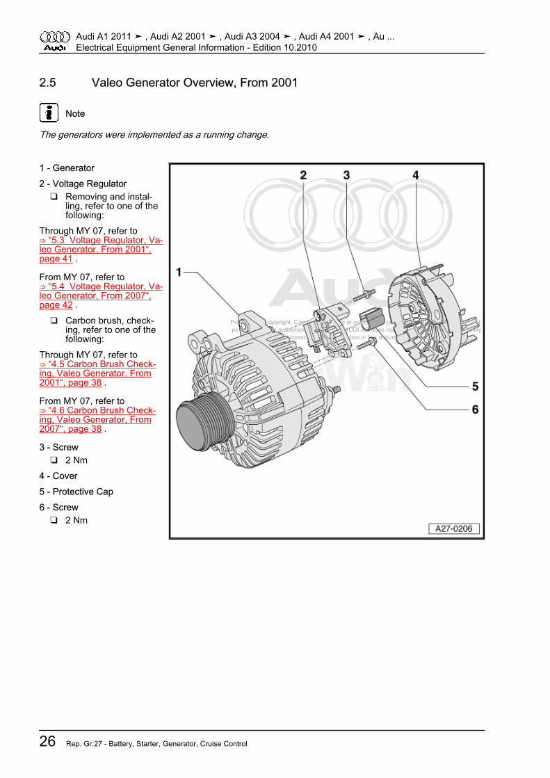
2.5 Valeo Generator Overview, From 2001
Note
The generators were implemented as a running change.
1 - Generator2 - Voltage Regulator
❑ Removing and instal‐ling, refer to one of thefollowing:
Through MY 07, refer to⇒ “5.3 Voltage Regulator, Va‐leo Generator, From 2001“,page 41 .
From MY 07, refer to⇒ “5.4 Voltage Regulator, Va‐leo Generator, From 2007“,page 42 .
❑ Carbon brush, check‐ing, refer to one of thefollowing:
Through MY 07, refer to⇒ “4.5 Carbon Brush Check‐ing, Valeo Generator, From2001“, page 38 .
From MY 07, refer to⇒ “4.6 Carbon Brush Check‐ing, Valeo Generator, From2007“, page 38 .
3 - Screw❑ 2 Nm
4 - Cover5 - Protective Cap6 - Screw
❑ 2 Nm
Audi A1 2011 ➤ , Audi A2 2001 ➤ , Audi A3 2004 ➤ , Audi A4 2001 ➤ , Au ...Electrical Equipment General Information - Edition 10.2010
26 Rep. Gr.27 - Battery, Starter, Generator, Cruise Control

Protected by copyright. Copying for private or commercial purposes, in part or in whole, is not permitted unless authorised by AUDI AG. AUDI AG does not guarantee or accept any liability with respect to the correctness of information in this document. Copyright by AUDI AG.
3 Specifications⇒ “3.1 Fastener Tightening Specifications“, page 27
3.1 Fastener Tightening SpecificationsComponent Nm
Pulley (with freewheel) to generator 80Pulley (without freewheel) to generator 65
Bosch Generator, Through 2000 Cover to Generator Screw 1Voltage Regulator to Generator Screw 2
Bosch Generator, from 2001Cover to Generator Nut1 12
30Cover to Generator Screw 3Voltage Regulator to Generator Screw2
2.51.5
Bosch Generator, from 2007Cover to Generator Screw 3Pulley to Generator Shaft Nut 65Voltage Regulator to Generator Screw3
2.51.5
Valeo Generator, through 2000Cover to Generator Nut 2Voltage Regulator to Generator Nut 3.5Voltage Regulator to Generator Screw 2
Valeo Generator, from 2001Voltage Regulator to Generator Stud Bolt/Screw 2• 1For clarification of the nuts, refer to items -5 and 6- in
⇒ “2.2 Bosch Generator Overview, From 2001“, page 23• 2 For clarification of the screws, refer to items -3 and 8- in
⇒ “2.2 Bosch Generator Overview, From 2001“, page 23• 3 For clarification of the screws, refer to items -5 and 8- in
⇒ “2.3 Bosch Generator Overview, From 2007“, page 24
Audi A1 2011 ➤ , Audi A2 2001 ➤ , Audi A3 2004 ➤ , Audi A4 2001 ➤ , Au ...Electrical Equipment General Information - Edition 10.2010
3. Specifications 27
Protected by copyright. Copying for private or commercial purposes, in part or in whole, is not permitted unless authorised by AUDI AG. AUDI AG does not guarantee or accept any liability with respect to the correctness of information in this document. Copyright by AUDI AG.
4 Diagnosis and Testing⇒ “4.1 Battery, Checking - Vehicles Without A Battery MonitoringControl Module J367 or Energy Management Control ModuleJ644 “, page 28⇒ “4.2 Battery Checking - Vehicles With A Battery MonitoringControl Module J367 Or Energy Management Control ModuleJ644 “, page 34⇒ “4.3 Generator, Checking“, page 37⇒ “4.4 Carbon Brush, Checking, Bosch Generators From 2001“,page 38⇒ “4.5 Carbon Brush Checking, Valeo Generator, From 2001“,page 38⇒ “4.6 Carbon Brush Checking, Valeo Generator, From 2007“,page 38
4.1 Battery, Checking - Vehicles Without ABattery Monitoring Control Module -J367- or Energy Management ControlModule -J644-
⇒ “4.1.1 Battery Test Using Battery Tester VAS 6161 “,page 28⇒ “4.1.2 Measuring No Load Voltage“, page 32⇒ “4.1.3 Current Draw Test “, page 33
4.1.1 Battery Test Using Battery Tester -VAS 6161-
Special tools and workshop equipment required♦ Battery Tester -VAS 6161-Maintenance-free batteries must not be opened. Otherwise, thewarranty is voided.♦ When performing the battery test with the -VAS 6161- , the
battery ground wire must not be disconnected.♦ When using the -VAS 6161- the battery is no longer being
charged. The principle of dynamic conductivity measurementis applied. As a result, numerous measurements are possiblewithout recharging the battery.
♦ The no-load voltage measurement can be performed withouta waiting period.
♦ All battery types are stored in the device. They can be re‐freshed by performing an update.
♦ The battery barcode can be directly recorded via the optional2D scanner.
♦ The integrated temperature sensor increases the quality of themeasurements.
♦ The data can be stored on a SD memory card.
Note
Information about the -VAS 6161- refer to the operating instruc‐tions.
Audi A1 2011 ➤ , Audi A2 2001 ➤ , Audi A3 2004 ➤ , Audi A4 2001 ➤ , Au ...Electrical Equipment General Information - Edition 10.2010
28 Rep. Gr.27 - Battery, Starter, Generator, Cruise Control

Protected by copyright. Copying for private or commercial purposes, in part or in whole, is not permitted unless authorised by AUDI AG. AUDI AG does not guarantee or accept any liability with respect to the correctness of information in this document. Copyright by AUDI AG.
Note
Using the -VAS 6161- , refer to the operating instructions.
Procedure• The battery temperature must be at least +10° C (50 °F).
WARNING
There is a risk of injury from the battery acid.♦ Follow accident prevention regulations when working with
battery acid. Refer to ⇒ page 9 .♦ Wear protective eyewear and clothing. Refer to
⇒ page 9 .♦ On non-maintenance-free batteries, the sealing plugs
must always be firmly tightened during the voltage underload measurement.
Risk of explosion on discharged battery with visual indicator.♦ If the visual indicator has no color or is light yellow, the
battery may not be tested or charged. Jump starting mustnot be used! There is a risk of explosion during testing,charging or jump starting. The battery must be replaced.
– Turn off the ignition and all electrical consumers.– On a battery with a visual indicator, check its color display.
Refer to⇒ “1.7.9 Electrolyte Level Color, Checking“, page 20 .
– Switch on the -VAS 6161- .– Clamp the red battery tester test clamp “+“ to the battery pos‐
itive terminal or the jump start terminal in the engine compart‐ment.
– Clamp the black battery tester test clamp “-“ to the batteryground terminal or the jump start terminal in the engine com‐partment.
Note
Make sure the test clamps make good contact!
– Select one of the following:♦ Maintenance test♦ Service test♦ Warranty testMaintenance test– Select “Maintenance Test“.– Connect the scanner and scan in the vehicle identification
number.– Select the connection type: “at the battery terminal“ or “at the
jump start terminal“.– Section vehicle model.
Audi A1 2011 ➤ , Audi A2 2001 ➤ , Audi A3 2004 ➤ , Audi A4 2001 ➤ , Au ...Electrical Equipment General Information - Edition 10.2010
4. Diagnosis and Testing 29
Protected by copyright. Copying for private or commercial purposes, in part or in whole, is not permitted unless authorised by AUDI AG. AUDI AG does not guarantee or accept any liability with respect to the correctness of information in this document. Copyright by AUDI AG.
– Scan in the battery barcode.– To determine the temperature, hold the temperature sensor
approximately 5 cm above the battery or the jump start termi‐nal until a constant temperature is shown.
– Start the test.– When necessary, print out the test protocol.Service test– Select “Service Test“.– Section vehicle model.– To determine the temperature, hold the temperature sensor
approximately 5 cm above the battery until a constant tem‐perature is shown.
– Select the type of battery: “Standard“, “AGM“, “2*6V“ or “Gel“.– Select the standard: “CCA“, “JIS“, “DIN“, “SAE“, “IEC“ or “EN“.– Start the test.– When necessary, print out the test protocol.Warranty test– Select “Warranty Test“.– Select the installation location: “inside the vehicle“ or “outside
the vehicle“.– Section vehicle model.– To determine the temperature, hold the temperature sensor
approximately 5 cm above the battery until a constant tem‐perature is shown.
– Select the type of battery: “Standard“, “AGM“, “2*6V“ or “Gel“.– Select the appropriate capacity with the arrow buttons.– Start the test.– When necessary, print out the test protocol.
Note
The printed test results are required for warranty claims.
– Switch off the battery tester.– Remove the test clamps.
Audi A1 2011 ➤ , Audi A2 2001 ➤ , Audi A3 2004 ➤ , Audi A4 2001 ➤ , Au ...Electrical Equipment General Information - Edition 10.2010
30 Rep. Gr.27 - Battery, Starter, Generator, Cruise Control

Protected by copyright. Copying for private or commercial purposes, in part or in whole, is not permitted unless authorised by AUDI AG. AUDI AG does not guarantee or accept any liability with respect to the correctness of information in this document. Copyright by AUDI AG.
Test Result On The Printout1 - Type of test2 - Test result3 - Measured voltage4 - Measured nominal value of the battery5 - Battery nominal value set at the tester6 - Temperature measured above the battery7 - Battery installed location8 - Location of the battery terminal set at the tester9 - Set battery type
Result of the Maintenance Test MeasuresBatter good Battery OK.Charge the battery immediately Charge the battery completely.
Refer to⇒ “1.2.1 Charging The BatteryUsing VAS 5903 “, page 2 andtest again. Errors can occur ifthe battery is not fully chargedand is retested.
Mark as defective Mark as “defective“ and removefrom the vehicle
Check the tester connection Disconnect the battery and testagain. The result “check thetester connection“ can occurbecause the cable contact isweak.
Check the connection Connect the cable directly tothe battery and not to the bat‐tery jump start terminal.
Audi A1 2011 ➤ , Audi A2 2001 ➤ , Audi A3 2004 ➤ , Audi A4 2001 ➤ , Au ...Electrical Equipment General Information - Edition 10.2010
4. Diagnosis and Testing 31
Protected by copyright. Copying for private or commercial purposes, in part or in whole, is not permitted unless authorised by AUDI AG. AUDI AG does not guarantee or accept any liability with respect to the correctness of information in this document. Copyright by AUDI AG.
Results of the Service Test andWarranty Test
Measures
Batter good Battery OK.Battery good - recharge Charge the battery completely,
refer to⇒ “1.2.1 Charging The BatteryUsing VAS 5903 “, page 2 . Ifnecessary, search for thecause of the discharging
Perform a current draw test Perform a current draw test, re‐fer to⇒ “4.1.3 Current Draw Test “,page 33 . Charge the batterycompletely. Refer to⇒ “1.2.1 Charging The BatteryUsing VAS 5903 “, page 2 andtest again.
Replace the battery Disconnect the battery and testagain. The result "replace thebattery" can occur due to aweak cable contact.
Battery cell faulty - replace Replace the batteryBattery frozen Thaw the battery and perform
the test againCheck the connection Connect the cable directly to
the battery and not to the bat‐tery jump start terminal.
Note
If the battery must be replaced, follow the disposal regulations.Refer to ⇒ page 11 .
4.1.2 Measuring No Load VoltageSpecial tools and workshop equipment required♦ Hand-Held Multimeter -V.A.G 1526E-Maintenance-free batteries must not be opened. Otherwise, thewarranty is voided.
Note
Measuring the no-load voltage, for example, during the prescri‐bed maintenance and service work on vehicles in storage, deter‐mines whether the battery must be recharged. Refer to Mainte‐nance Intervals Rep. Gr. 03.
ProcedureTo ensure a correct measurement, the following points must befollowed.• Battery must not be loaded by electrical consumers within the
next 2 hours before measurement.• After battery charging or engine operation, the measurement
can be performed only after a 12 hour waiting period.• The battery temperature must be at least 10° C (50 °F).After a waiting period of at least 12 hours:
Audi A1 2011 ➤ , Audi A2 2001 ➤ , Audi A3 2004 ➤ , Audi A4 2001 ➤ , Au ...Electrical Equipment General Information - Edition 10.2010
32 Rep. Gr.27 - Battery, Starter, Generator, Cruise Control
Protected by copyright. Copying for private or commercial purposes, in part or in whole, is not permitted unless authorised by AUDI AG. AUDI AG does not guarantee or accept any liability with respect to the correctness of information in this document. Copyright by AUDI AG.
– Measure the voltage between the battery terminal clamps.• Specified value: 12.5 volts or higher, the battery is OK.– If the no-load voltage is under 12.5 volts, the battery must be
recharged. Refer to⇒ “1.2.1 Charging The Battery Using VAS 5903 “, page 2 .
– After charging for 5 minutes, the current draw must be meas‐ured again. Refer to⇒ “4.1.3 Current Draw Test “, page 33 .
– If the battery no-load voltage is 11.6 volts or lower, the batteryis exhaustively discharged. Refer to ⇒ page 3 .
4.1.3 Current Draw TestSpecial tools and workshop equipment required♦ Battery Charger VAS 5903 -VAS 5903-Maintenance-free batteries must not be opened. Otherwise, thewarranty is voided.By checking a battery's current draw capacity during charging, adecision can be quickly made as to whether a partially or exhaus‐tively discharged battery, refer to⇒ “1.2.2 Exhaustively Discharged Battery“, page 3 can be madeusable again by recharging or if it must be replaced.
Note
♦ When charging with the battery charger, -VAS 5903- , displaysthe current draw on the device.
♦ For more information regarding the battery charger, refer tothe Operating Instructions that came with the charger.
Procedure• The battery temperature must be at least +10° C (50 °F).• The battery charger must be able to deliver at least 30 amps
(A), as with the battery charger -VAS 5903- .• Battery charger connected and switched on.– Measure the battery charge current after 5 minutes of charg‐
ing.• Specified value: The charge current must be higher than 10%
of the nominal capacity.• Example: Charge current on a 60 Ah battery after 5 minutes
of charging: greater than 6 A.– If the target value is reached, proceed with the charging op‐
eration until the battery is fully charged.– Then test the battery with the battery tester:♦ With the Battery tester -VAS 6161- without waiting period, re‐
fer to⇒ “4.1.1 Battery Test Using Battery Tester VAS 6161 “, page28 .
– If the specified value is not met, replace the battery. Refer to⇒ Electrical Equipment; Rep. Gr. 27 ; Removal and Installation .
Audi A1 2011 ➤ , Audi A2 2001 ➤ , Audi A3 2004 ➤ , Audi A4 2001 ➤ , Au ...Electrical Equipment General Information - Edition 10.2010
4. Diagnosis and Testing 33
Protected by copyright. Copying for private or commercial purposes, in part or in whole, is not permitted unless authorised by AUDI AG. AUDI AG does not guarantee or accept any liability with respect to the correctness of information in this document. Copyright by AUDI AG.
Note
If the battery must be replaced, follow the disposal regulations.Refer to ⇒ page 11 .
4.2 Battery Checking - Vehicles With A Bat‐tery Monitoring Control Module -J367-Or Energy Management Control Module-J644-
⇒ “4.2.1 General Information“, page 34⇒ “4.2.2 Battery Test with Vehicle Diagnosis Tester -“,page 34⇒ “4.2.3 Current Draw Test“, page 35⇒ “4.2.4 Measuring No-Load Voltage, Transport Mode Not Ac‐tive“, page 36⇒ “4.2.5 Measuring No-Load Voltage, Transport Mode Active“,page 37
4.2.1 General Information♦ In certain model series the following is responsible for moni‐
toring the electrical system: energy management control mod‐ule -J644- or battery monitoring control module -J367- inconnection with the data bus on board diagnostic interface -J533- ; allocation, refer to ⇒ Wiring diagrams, Troubleshooting& Component locations. The battery test for these vehicles isperformed during “Guided Fault Finding“.
♦ If the battery test is not possible with “Guided Fault Finding“due to a partially or exhaustively discharged battery, the bat‐tery can be quickly evaluated with the help of the “current drawtest“.
♦ Maintenance-free batteries must not be opened. Otherwise,the warranty is voided.
4.2.2 Battery Test with Vehicle DiagnosisTester -
Special tools and workshop equipment required♦ Vehicle testerProcedure• No charging unit must be connected when checking the bat‐
tery, and the engine must not be running.• The battery temperature must be at least –10 °C (14 °F).• Diagnostic system temperature must be between +5 and 45 °
C (41 and 113 °F)..– Connect the Vehicle Diagnosis Tester. Refer to
⇒ “1.6.2 Connecting the Vehicle Diagnosis Tester“,page 85 .
Note
If a malfunction message appears in the display, refer to the Ve‐hicle Diagnosis Tester Operating Instructions.
Audi A1 2011 ➤ , Audi A2 2001 ➤ , Audi A3 2004 ➤ , Audi A4 2001 ➤ , Au ...Electrical Equipment General Information - Edition 10.2010
34 Rep. Gr.27 - Battery, Starter, Generator, Cruise Control
Protected by copyright. Copying for private or commercial purposes, in part or in whole, is not permitted unless authorised by AUDI AG. AUDI AG does not guarantee or accept any liability with respect to the correctness of information in this document. Copyright by AUDI AG.
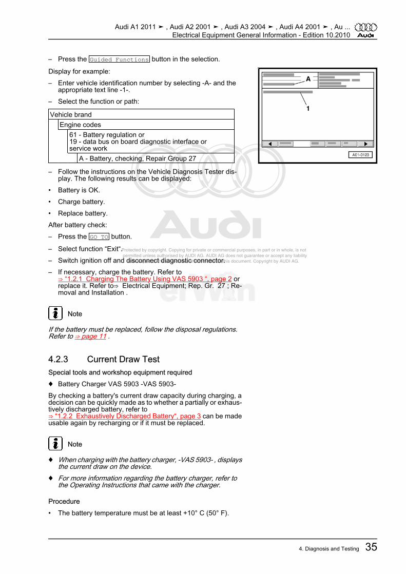
– Press the Guided Functions button in the selection.
Display for example:– Enter vehicle identification number by selecting -A- and the
appropriate text line -1-.– Select the function or path:
Vehicle brand Engine codes 61 - Battery regulation or
19 - data bus on board diagnostic interface orservice work
A - Battery, checking, Repair Group 27
– Follow the instructions on the Vehicle Diagnosis Tester dis‐play. The following results can be displayed:
• Battery is OK.• Charge battery.• Replace battery.After battery check:– Press the GO TO button.
– Select function “Exit“.– Switch ignition off and disconnect diagnostic connector.– If necessary, charge the battery. Refer to
⇒ “1.2.1 Charging The Battery Using VAS 5903 “, page 2 orreplace it. Refer to⇒ Electrical Equipment; Rep. Gr. 27 ; Re‐moval and Installation .
Note
If the battery must be replaced, follow the disposal regulations.Refer to ⇒ page 11 .
4.2.3 Current Draw TestSpecial tools and workshop equipment required♦ Battery Charger VAS 5903 -VAS 5903-By checking a battery's current draw capacity during charging, adecision can be quickly made as to whether a partially or exhaus‐tively discharged battery, refer to⇒ “1.2.2 Exhaustively Discharged Battery“, page 3 can be madeusable again by recharging or if it must be replaced.
Note
♦ When charging with the battery charger, -VAS 5903- , displaysthe current draw on the device.
♦ For more information regarding the battery charger, refer tothe Operating Instructions that came with the charger.
Procedure• The battery temperature must be at least +10° C (50° F).
Audi A1 2011 ➤ , Audi A2 2001 ➤ , Audi A3 2004 ➤ , Audi A4 2001 ➤ , Au ...Electrical Equipment General Information - Edition 10.2010
4. Diagnosis and Testing 35

Protected by copyright. Copying for private or commercial purposes, in part or in whole, is not permitted unless authorised by AUDI AG. AUDI AG does not guarantee or accept any liability with respect to the correctness of information in this document. Copyright by AUDI AG.
• The battery charger must be able to deliver at least 30 amps(A), as with the battery charger -VAS 5903- .
• Battery charger connected and switched on.– Measure the battery charge current after 5 minutes of charg‐
ing.• Specified value: The charge current must be higher than 10%
of the nominal capacity.• Example: Charge current on a 60 Ah battery after 5 minutes
of charging: greater than 6 A.– If the target value is reached, proceed with the charging op‐
eration until the battery is fully charged.– Then test the battery with the vehicle diagnostic tester. Refer
to⇒ “4.2.2 Battery Test with Vehicle Diagnosis Tester -“,page 34 .
– If the specified value is not met, replace the battery. Refer to⇒ Electrical Equipment; Rep. Gr. 27 ; Removal and Installation .
Note
If the battery must be replaced, follow the disposal regulations.Refer to ⇒ page 11 .
4.2.4 Measuring No-Load Voltage, TransportMode Not Active
Special tools and workshop equipment required♦ Hand-Held Multimeter -V.A.G 1526E-
Note
The no-load voltage measurement should only be used to eval‐uate the battery condition if it is not possible to perform the batterytest with the Vehicle Diagnosis Tester and if the transport modeis not activated in the battery monitoring control module -J367- orenergy management control module -J644- .
Procedure– Always observe the following to ensure correct measurement:• Battery remains installed in vehicle, battery ground (GND)
strap must not be disconnected.• Open the front lid or rear lid and lock the lid lock in the closed
position so that the luggage compartment lamp is not switchedon.
• Lock vehicle with central locking system.• Battery must not be loaded by electrical consumers within the
next 2 hours before measurement.• Battery must not be charged within the next 12 hours before
measurement.• The battery temperature must be at least –10 °C (14 °F).– Perform the prep work for the no-load voltage measurement.
Refer to⇒ Electrical Equipment; Rep. Gr. 27 ; Description andOperation .
Audi A1 2011 ➤ , Audi A2 2001 ➤ , Audi A3 2004 ➤ , Audi A4 2001 ➤ , Au ...Electrical Equipment General Information - Edition 10.2010
36 Rep. Gr.27 - Battery, Starter, Generator, Cruise Control

Protected by copyright. Copying for private or commercial purposes, in part or in whole, is not permitted unless authorised by AUDI AG. AUDI AG does not guarantee or accept any liability with respect to the correctness of information in this document. Copyright by AUDI AG.
After a waiting period of at least 2 hours:– Connect the -V.A.G 1526E- between the battery terminal
clamps or to the positive terminal “+“ and ground terminal “–“.– Measure the voltage between the battery terminal clamps.• Specified value: 12.5 volts or higher, the battery is OK.– If the no-load voltage is under 12.5 volts, the battery must be
recharged. Refer to⇒ “1.2.1 Charging The Battery Using VAS 5903 “, page 2 .
– After charging for 5 minutes, the current draw must be meas‐ured again. Refer to ⇒ “4.2.3 Current Draw Test“, page 35 .
– If the battery no-load voltage is 11.6 volts or lower, the batteryis exhaustively discharged. Refer to⇒ “1.2.2 Exhaustively Discharged Battery“, page 3 .
4.2.5 Measuring No-Load Voltage, TransportMode Active
Note
During the prescribed maintenance and service work on vehiclesin storage, the charge state can be read in % (SOC = state ofcharge) in the trip odometer display when the transport mode isactive. This determines whether the battery needs to be fullycharged. Refer to Maintenance Intervals Rep. Gr. 03.
ProcedureThe following test is only possible if the transport mode is activein the battery monitoring control module -J367- or energy man‐agement control module -J644- . If the transport mode is activatedlater, for example, when storing used vehicles, the SOC can firstbe determined when “the bus is at rest“.– Open the driver door.– Switch ignition on.– Read the SOC in % on the trip odometer display.
Note
Depending on the version, “TRA“ can precede the value.
• Specified value: 50% or higher, the battery charge level is OK.– If the battery charge level is less than 50%, the battery must
be fully charged. Refer to ⇒ “1.2 Battery, Charging“, page 2 .– After charging for 5 minutes, the current draw must be meas‐
ured again. Refer to ⇒ “4.2.3 Current Draw Test“, page 35 .– If the battery charge level is 0%, the battery is exhaustively
discharged. Refer to⇒ “1.2.2 Exhaustively Discharged Battery“, page 3 .
4.3 Generator, Checking– Test the generator in “Guided Fault Finding“ under “Body/
Electrical System/26 - Starter, voltage supply/electrical com‐ponents/C generator, testing“, refer to Vehicle Diagnosis,Testing & Information System -VAS5051B- .
Audi A1 2011 ➤ , Audi A2 2001 ➤ , Audi A3 2004 ➤ , Audi A4 2001 ➤ , Au ...Electrical Equipment General Information - Edition 10.2010
4. Diagnosis and Testing 37

Protected by copyright. Copying for private or commercial purposes, in part or in whole, is not permitted unless authorised by AUDI AG. AUDI AG does not guarantee or accept any liability with respect to the correctness of information in this document. Copyright by AUDI AG.
4.4 Carbon Brush, Checking, Bosch Gener‐ators From 2001
Procedure– Remove the voltage regulator, refer to one of the following:Through MY 07, refer to⇒ “5.1 Voltage Regulator, Bosch Generator, From 2001“,page 40 .From MY 07, refer to⇒ “5.2 Voltage Regulator, Bosch Generator, From 2007“,page 40 .– Check carbon brushes for length -a-.• Wear limit: -a- = 5 mm.– Install the voltage regulator, refer to one of the following:Through MY 07, refer to⇒ “5.1 Voltage Regulator, Bosch Generator, From 2001“,page 40 .From MY 07, refer to⇒ “5.2 Voltage Regulator, Bosch Generator, From 2007“,page 40 .
4.5 Carbon Brush Checking, Valeo Gener‐ator, From 2001
Procedure– Remove voltage regulator. Refer to
⇒ “5.3 Voltage Regulator, Valeo Generator, From 2001“, page41 .
– Check carbon brushes for length -a-.• Wear limit: -a- = 5 mm.– Install the voltage regulator. Refer to
⇒ “5.3 Voltage Regulator, Valeo Generator, From 2001“, page41 .
4.6 Carbon Brush Checking, Valeo Gener‐ator, From 2007
Special tools and workshop equipment required♦ Feeler Gauge 0.3 mm
Audi A1 2011 ➤ , Audi A2 2001 ➤ , Audi A3 2004 ➤ , Audi A4 2001 ➤ , Au ...Electrical Equipment General Information - Edition 10.2010
38 Rep. Gr.27 - Battery, Starter, Generator, Cruise Control
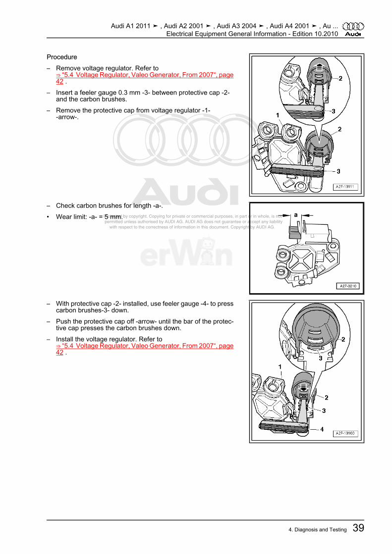
Protected by copyright. Copying for private or commercial purposes, in part or in whole, is not permitted unless authorised by AUDI AG. AUDI AG does not guarantee or accept any liability with respect to the correctness of information in this document. Copyright by AUDI AG.
Procedure– Remove voltage regulator. Refer to
⇒ “5.4 Voltage Regulator, Valeo Generator, From 2007“, page42 .
– Insert a feeler gauge 0.3 mm -3- between protective cap -2-and the carbon brushes.
– Remove the protective cap from voltage regulator -1--arrow-.
– Check carbon brushes for length -a-.• Wear limit: -a- = 5 mm.
– With protective cap -2- installed, use feeler gauge -4- to presscarbon brushes-3- down.
– Push the protective cap off -arrow- until the bar of the protec‐tive cap presses the carbon brushes down.
– Install the voltage regulator. Refer to⇒ “5.4 Voltage Regulator, Valeo Generator, From 2007“, page42 .
Audi A1 2011 ➤ , Audi A2 2001 ➤ , Audi A3 2004 ➤ , Audi A4 2001 ➤ , Au ...Electrical Equipment General Information - Edition 10.2010
4. Diagnosis and Testing 39
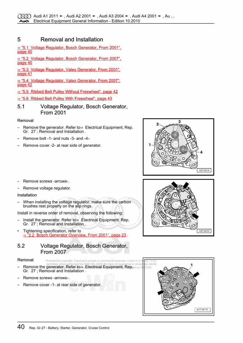
Protected by copyright. Copying for private or commercial purposes, in part or in whole, is not permitted unless authorised by AUDI AG. AUDI AG does not guarantee or accept any liability with respect to the correctness of information in this document. Copyright by AUDI AG.
5 Removal and Installation⇒ “5.1 Voltage Regulator, Bosch Generator, From 2001“,page 40⇒ “5.2 Voltage Regulator, Bosch Generator, From 2007“,page 40⇒ “5.3 Voltage Regulator, Valeo Generator, From 2001“,page 41⇒ “5.4 Voltage Regulator, Valeo Generator, From 2007“,page 42⇒ “5.5 Ribbed Belt Pulley Without Freewheel“, page 42⇒ “5.6 Ribbed Belt Pulley With Freewheel“, page 43
5.1 Voltage Regulator, Bosch Generator,From 2001
Removal– Remove the generator. Refer to⇒ Electrical Equipment; Rep.
Gr. 27 ; Removal and Installation .– Remove bolt -1- and nuts -3- and -4-.– Remove cover -2- at rear side of generator.
– Remove screws -arrows-.– Remove voltage regulator.Installation– When installing the voltage regulator, make sure the carbon
brushes rest properly on the slip rings.Install in reverse order of removal, observing the following:– Install the generator. Refer to⇒ Electrical Equipment; Rep.
Gr. 27 ; Removal and Installation .• Tightening specification, refer to
⇒ “2.2 Bosch Generator Overview, From 2001“, page 23 .
5.2 Voltage Regulator, Bosch Generator,From 2007
Removal– Remove the generator. Refer to⇒ Electrical Equipment; Rep.
Gr. 27 ; Removal and Installation .– Remove screws -arrows-.– Remove cover -1- at rear side of generator.
Audi A1 2011 ➤ , Audi A2 2001 ➤ , Audi A3 2004 ➤ , Audi A4 2001 ➤ , Au ...Electrical Equipment General Information - Edition 10.2010
40 Rep. Gr.27 - Battery, Starter, Generator, Cruise Control
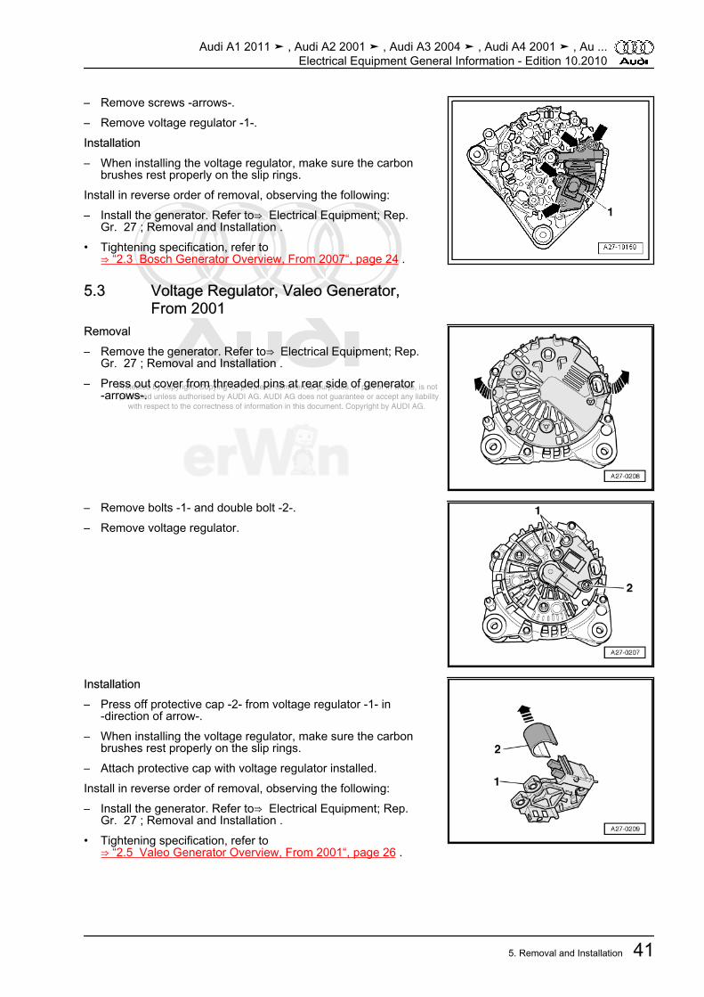
Protected by copyright. Copying for private or commercial purposes, in part or in whole, is not permitted unless authorised by AUDI AG. AUDI AG does not guarantee or accept any liability with respect to the correctness of information in this document. Copyright by AUDI AG.
– Remove screws -arrows-.– Remove voltage regulator -1-.Installation– When installing the voltage regulator, make sure the carbon
brushes rest properly on the slip rings.Install in reverse order of removal, observing the following:– Install the generator. Refer to⇒ Electrical Equipment; Rep.
Gr. 27 ; Removal and Installation .• Tightening specification, refer to
⇒ “2.3 Bosch Generator Overview, From 2007“, page 24 .
5.3 Voltage Regulator, Valeo Generator,From 2001
Removal– Remove the generator. Refer to⇒ Electrical Equipment; Rep.
Gr. 27 ; Removal and Installation .– Press out cover from threaded pins at rear side of generator
-arrows-.
– Remove bolts -1- and double bolt -2-.– Remove voltage regulator.
Installation– Press off protective cap -2- from voltage regulator -1- in
-direction of arrow-.– When installing the voltage regulator, make sure the carbon
brushes rest properly on the slip rings.– Attach protective cap with voltage regulator installed.Install in reverse order of removal, observing the following:– Install the generator. Refer to⇒ Electrical Equipment; Rep.
Gr. 27 ; Removal and Installation .• Tightening specification, refer to
⇒ “2.5 Valeo Generator Overview, From 2001“, page 26 .
Audi A1 2011 ➤ , Audi A2 2001 ➤ , Audi A3 2004 ➤ , Audi A4 2001 ➤ , Au ...Electrical Equipment General Information - Edition 10.2010
5. Removal and Installation 41
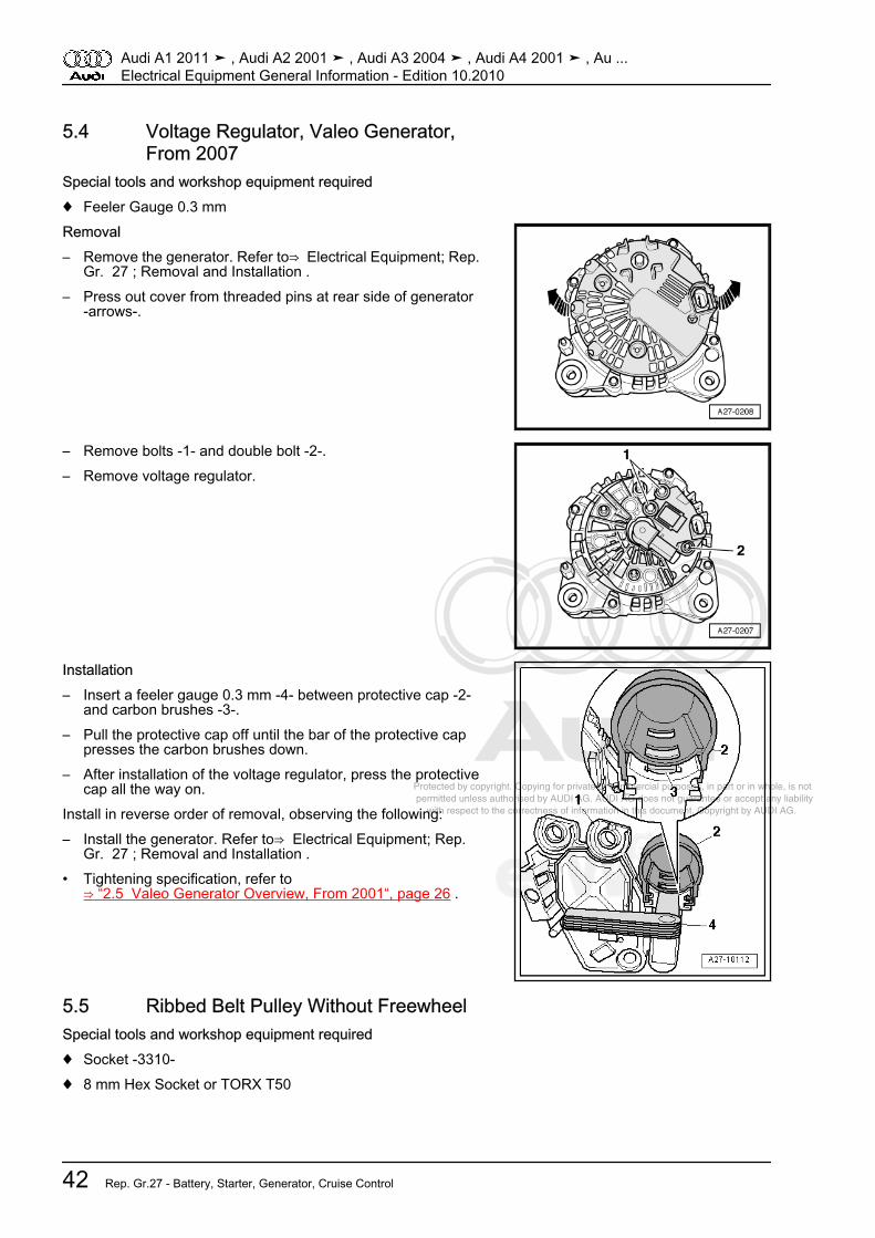
Protected by copyright. Copying for private or commercial purposes, in part or in whole, is not permitted unless authorised by AUDI AG. AUDI AG does not guarantee or accept any liability with respect to the correctness of information in this document. Copyright by AUDI AG.
5.4 Voltage Regulator, Valeo Generator,From 2007
Special tools and workshop equipment required♦ Feeler Gauge 0.3 mmRemoval– Remove the generator. Refer to⇒ Electrical Equipment; Rep.
Gr. 27 ; Removal and Installation .– Press out cover from threaded pins at rear side of generator
-arrows-.
– Remove bolts -1- and double bolt -2-.– Remove voltage regulator.
Installation– Insert a feeler gauge 0.3 mm -4- between protective cap -2-
and carbon brushes -3-.– Pull the protective cap off until the bar of the protective cap
presses the carbon brushes down.– After installation of the voltage regulator, press the protective
cap all the way on.Install in reverse order of removal, observing the following:– Install the generator. Refer to⇒ Electrical Equipment; Rep.
Gr. 27 ; Removal and Installation .• Tightening specification, refer to
⇒ “2.5 Valeo Generator Overview, From 2001“, page 26 .
5.5 Ribbed Belt Pulley Without FreewheelSpecial tools and workshop equipment required♦ Socket -3310-♦ 8 mm Hex Socket or TORX T50
Audi A1 2011 ➤ , Audi A2 2001 ➤ , Audi A3 2004 ➤ , Audi A4 2001 ➤ , Au ...Electrical Equipment General Information - Edition 10.2010
42 Rep. Gr.27 - Battery, Starter, Generator, Cruise Control
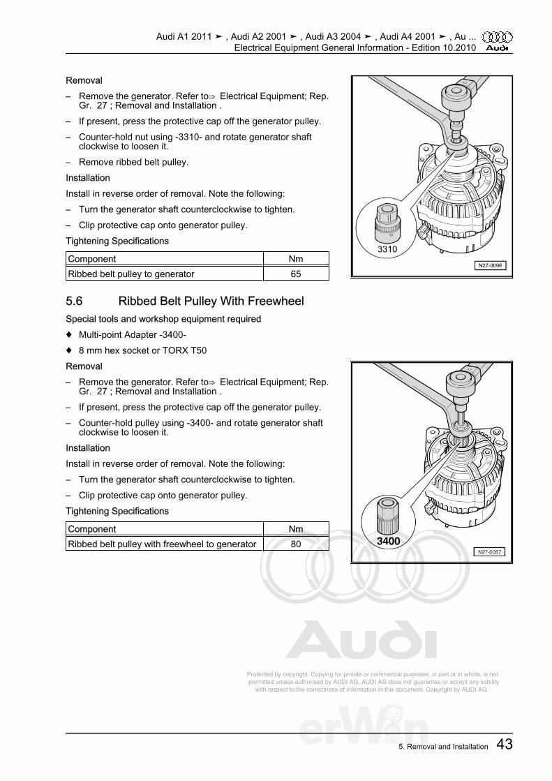
Protected by copyright. Copying for private or commercial purposes, in part or in whole, is not permitted unless authorised by AUDI AG. AUDI AG does not guarantee or accept any liability with respect to the correctness of information in this document. Copyright by AUDI AG.
Removal– Remove the generator. Refer to⇒ Electrical Equipment; Rep.
Gr. 27 ; Removal and Installation .– If present, press the protective cap off the generator pulley.– Counter-hold nut using -3310- and rotate generator shaft
clockwise to loosen it.– Remove ribbed belt pulley.InstallationInstall in reverse order of removal. Note the following:– Turn the generator shaft counterclockwise to tighten.– Clip protective cap onto generator pulley.Tightening Specifications
Component NmRibbed belt pulley to generator 65
5.6 Ribbed Belt Pulley With FreewheelSpecial tools and workshop equipment required♦ Multi-point Adapter -3400-♦ 8 mm hex socket or TORX T50Removal– Remove the generator. Refer to⇒ Electrical Equipment; Rep.
Gr. 27 ; Removal and Installation .– If present, press the protective cap off the generator pulley.– Counter-hold pulley using -3400- and rotate generator shaft
clockwise to loosen it.InstallationInstall in reverse order of removal. Note the following:– Turn the generator shaft counterclockwise to tighten.– Clip protective cap onto generator pulley.Tightening Specifications
Component NmRibbed belt pulley with freewheel to generator 80
Audi A1 2011 ➤ , Audi A2 2001 ➤ , Audi A3 2004 ➤ , Audi A4 2001 ➤ , Au ...Electrical Equipment General Information - Edition 10.2010
5. Removal and Installation 43

Protected by copyright. Copying for private or commercial purposes, in part or in whole, is not permitted unless authorised by AUDI AG. AUDI AG does not guarantee or accept any liability with respect to the correctness of information in this document. Copyright by AUDI AG.
6 Special Tools
Audi A1 2011 ➤ , Audi A2 2001 ➤ , Audi A3 2004 ➤ , Audi A4 2001 ➤ , Au ...Electrical Equipment General Information - Edition 10.2010
44 Rep. Gr.27 - Battery, Starter, Generator, Cruise Control

Protected by copyright. Copying for private or commercial purposes, in part or in whole, is not permitted unless authorised by AUDI AG. AUDI AG does not guarantee or accept any liability with respect to the correctness of information in this document. Copyright by AUDI AG.
♦ Socket -3310-♦ Multi-point Adapter -3400-♦ 8 mm Hex Socket or TORX T50♦ Feeler Gauge 0.3 mm♦ Refractometer -T10007- or♦ Commercially Available Hydrometer♦ Hand-Held Multimeter -V.A.G 1526E-♦ Battery Charger VAS 5903 -VAS 5903-♦ Solar Panel -VAS 6102 A-♦ Battery Tester -VAS 6161-
Audi A1 2011 ➤ , Audi A2 2001 ➤ , Audi A3 2004 ➤ , Audi A4 2001 ➤ , Au ...Electrical Equipment General Information - Edition 10.2010
6. Special Tools 45
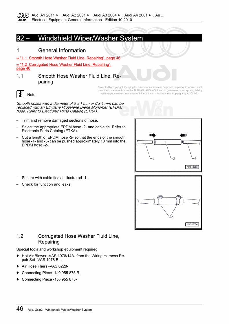
Protected by copyright. Copying for private or commercial purposes, in part or in whole, is not permitted unless authorised by AUDI AG. AUDI AG does not guarantee or accept any liability with respect to the correctness of information in this document. Copyright by AUDI AG.
92 – Windshield Wiper/Washer System1 General Information⇒ “1.1 Smooth Hose Washer Fluid Line, Repairing“, page 46⇒ “1.2 Corrugated Hose Washer Fluid Line, Repairing“,page 46
1.1 Smooth Hose Washer Fluid Line, Re‐pairing
Note
Smooth hoses with a diameter of 5 x 1 mm or 6 x 1 mm can bereplaced with an Ethylene Propylene Diene Monomer (EPDM)hose. Refer to Electronic Parts Catalog (ETKA).
– Trim and remove damaged sections of hose.– Select the appropriate EPDM hose -2- and cable tie. Refer to
Electronic Parts Catalog (ETKA).– Cut a length of EPDM hose -2- so that the ends of the smooth
hose -1- and -3- can be pushed approximately 10 mm into theEPDM hose -2-.
– Secure with cable ties as illustrated -1-.– Check for function and leaks.
1.2 Corrugated Hose Washer Fluid Line,Repairing
Special tools and workshop equipment required♦ Hot Air Blower -VAS 1978/14A- from the Wiring Harness Re‐
pair Set -VAS 1978 B- .♦ Air Hose Pliers -VAS 6228-♦ Connecting Piece -1J0 955 875 R-♦ Connecting Piece -1J0 955 875-
Audi A1 2011 ➤ , Audi A2 2001 ➤ , Audi A3 2004 ➤ , Audi A4 2001 ➤ , Au ...Electrical Equipment General Information - Edition 10.2010
46 Rep. Gr.92 - Windshield Wiper/Washer System
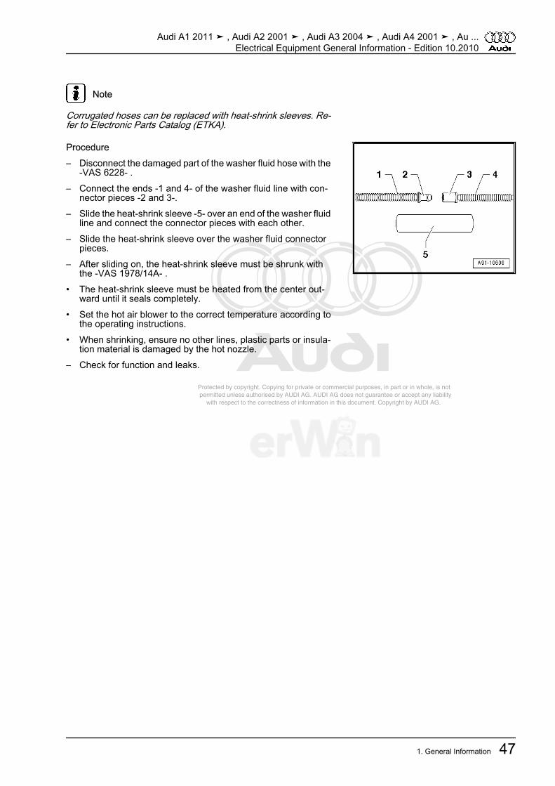
Protected by copyright. Copying for private or commercial purposes, in part or in whole, is not permitted unless authorised by AUDI AG. AUDI AG does not guarantee or accept any liability with respect to the correctness of information in this document. Copyright by AUDI AG.
Note
Corrugated hoses can be replaced with heat-shrink sleeves. Re‐fer to Electronic Parts Catalog (ETKA).
Procedure– Disconnect the damaged part of the washer fluid hose with the
-VAS 6228- .– Connect the ends -1 and 4- of the washer fluid line with con‐
nector pieces -2 and 3-.– Slide the heat-shrink sleeve -5- over an end of the washer fluid
line and connect the connector pieces with each other.– Slide the heat-shrink sleeve over the washer fluid connector
pieces.– After sliding on, the heat-shrink sleeve must be shrunk with
the -VAS 1978/14A- .• The heat-shrink sleeve must be heated from the center out‐
ward until it seals completely.• Set the hot air blower to the correct temperature according to
the operating instructions.• When shrinking, ensure no other lines, plastic parts or insula‐
tion material is damaged by the hot nozzle.– Check for function and leaks.
Audi A1 2011 ➤ , Audi A2 2001 ➤ , Audi A3 2004 ➤ , Audi A4 2001 ➤ , Au ...Electrical Equipment General Information - Edition 10.2010
1. General Information 47

Protected by copyright. Copying for private or commercial purposes, in part or in whole, is not permitted unless authorised by AUDI AG. AUDI AG does not guarantee or accept any liability with respect to the correctness of information in this document. Copyright by AUDI AG.
2 Removal and Installation⇒ “2.1 Washer Fluid Line Hose Connections, Disconnecting andConnecting“, page 48
2.1 Washer Fluid Line Hose Connections,Disconnecting and Connecting
Special tools and workshop equipment required♦ Hose Clamp Pliers -V.A.G 1275-♦ Hose Clamp Pliers -V.A.G 1921-Various hose couplings are used to connect the hoses to thewasher fluid pumps and spray jets or as separating points.Unsecured Hose Coupling– To disconnect the connection, pull both parts of the coupling
apart.– To connect, press both parts of the coupling together firmly
until they noticeably engage.
Secured Hose Coupling With Circlip– To disconnect the connection, turn the circlip -1- 90° -arrow-
and remove the hose connector.– To connect, attach the hose connector and turn circlip -1-
-arrow- until it engages.
Secured Hose Coupling With Circlip, Version 1– To disconnect the connection, pull circlip -1- up approximately
1 mm -arrow- and remove the hose connector.– To connect, attach the hose connector and press the circlip in
until it engages.
Audi A1 2011 ➤ , Audi A2 2001 ➤ , Audi A3 2004 ➤ , Audi A4 2001 ➤ , Au ...Electrical Equipment General Information - Edition 10.2010
48 Rep. Gr.92 - Windshield Wiper/Washer System
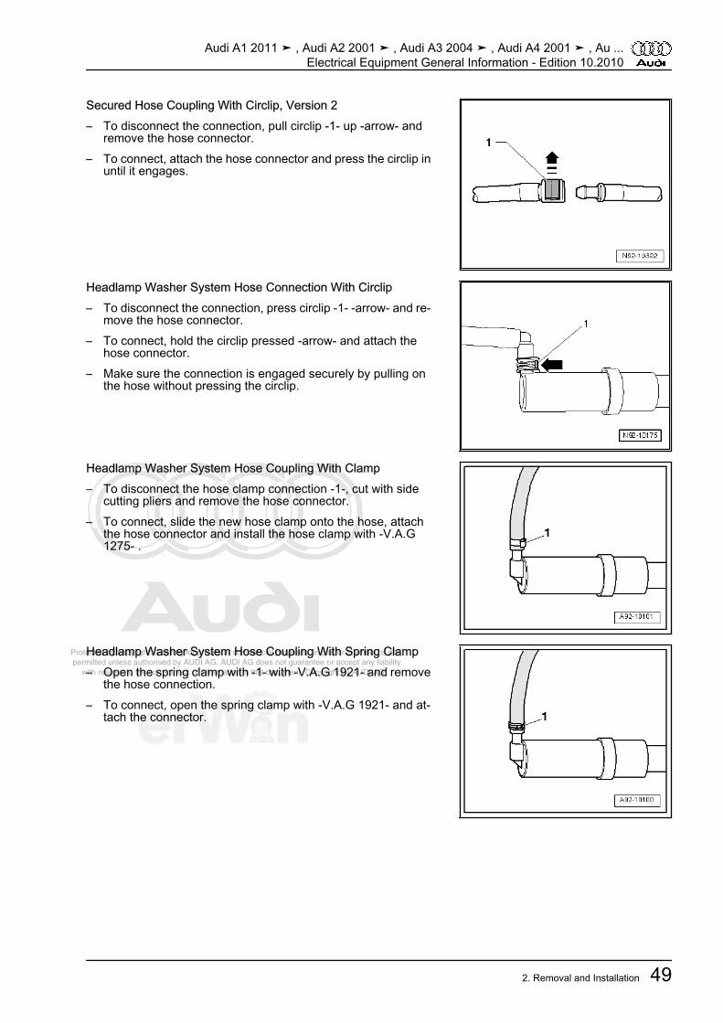
Protected by copyright. Copying for private or commercial purposes, in part or in whole, is not permitted unless authorised by AUDI AG. AUDI AG does not guarantee or accept any liability with respect to the correctness of information in this document. Copyright by AUDI AG.
Secured Hose Coupling With Circlip, Version 2– To disconnect the connection, pull circlip -1- up -arrow- and
remove the hose connector.– To connect, attach the hose connector and press the circlip in
until it engages.
Headlamp Washer System Hose Connection With Circlip– To disconnect the connection, press circlip -1- -arrow- and re‐
move the hose connector.– To connect, hold the circlip pressed -arrow- and attach the
hose connector.– Make sure the connection is engaged securely by pulling on
the hose without pressing the circlip.
Headlamp Washer System Hose Coupling With Clamp– To disconnect the hose clamp connection -1-, cut with side
cutting pliers and remove the hose connector.– To connect, slide the new hose clamp onto the hose, attach
the hose connector and install the hose clamp with -V.A.G1275- .
Headlamp Washer System Hose Coupling With Spring Clamp– Open the spring clamp with -1- with -V.A.G 1921- and remove
the hose connection.– To connect, open the spring clamp with -V.A.G 1921- and at‐
tach the connector.
Audi A1 2011 ➤ , Audi A2 2001 ➤ , Audi A3 2004 ➤ , Audi A4 2001 ➤ , Au ...Electrical Equipment General Information - Edition 10.2010
2. Removal and Installation 49
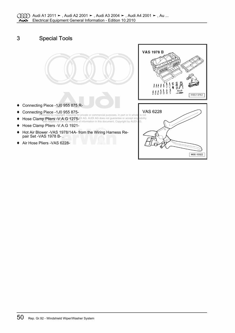
Protected by copyright. Copying for private or commercial purposes, in part or in whole, is not permitted unless authorised by AUDI AG. AUDI AG does not guarantee or accept any liability with respect to the correctness of information in this document. Copyright by AUDI AG.
3 Special Tools
♦ Connecting Piece -1J0 955 875 R-♦ Connecting Piece -1J0 955 875-♦ Hose Clamp Pliers -V.A.G 1275-♦ Hose Clamp Pliers -V.A.G 1921-♦ Hot Air Blower -VAS 1978/14A- from the Wiring Harness Re‐
pair Set -VAS 1978 B- .♦ Air Hose Pliers -VAS 6228-
Audi A1 2011 ➤ , Audi A2 2001 ➤ , Audi A3 2004 ➤ , Audi A4 2001 ➤ , Au ...Electrical Equipment General Information - Edition 10.2010
50 Rep. Gr.92 - Windshield Wiper/Washer System
Protected by copyright. Copying for private or commercial purposes, in part or in whole, is not permitted unless authorised by AUDI AG. AUDI AG does not guarantee or accept any liability with respect to the correctness of information in this document. Copyright by AUDI AG.
94 – Exterior Lights, Switches1 General Information⇒ “1.1 HID Headlamps, Usage and Safety Precautions“,page 51
1.1 HID Headlamps, Usage and Safety Pre‐cautions
Never replace bulbs if you are not familiar with the procedures,safety precautions and tools.
WARNING
Danger to life due to high voltage.♦ Always disconnect the battery ground cable before work‐
ing on gas-discharge headlamp components marked withyellow high-voltage symbols.
♦ Then switch low beams on and back off. This removes anypossible residual voltage.
♦ Turn off the ignition and all electrical consumers and re‐move the ignition key.
♦ The gas-discharge lamp control module should not be op‐erated without the gas-discharge lamp.
♦ Due to the high voltage (over 28000 volts when ignitingthe lamp), the gas-discharge lamp should only be operat‐ed inside the headlamp housing.
WARNING
Risk of injury due to burning, Ultra Violet (UV) rays, blindingand explosion.♦ Due the high temperatures, absorption of UV rays, and the
risk of blinding, the gas-discharge lamp should only beoperated inside the headlamp housing.
♦ Do not look into the beam of light. It may interfere with theability to see for a significant period of time.
♦ Gas-discharge lamps are under pressure and can crackwhen bulbs are replaced.
♦ When removing and installing HID bulbs, always wearsafety glasses and gloves.
Audi A1 2011 ➤ , Audi A2 2001 ➤ , Audi A3 2004 ➤ , Audi A4 2001 ➤ , Au ...Electrical Equipment General Information - Edition 10.2010
1. General Information 51

Protected by copyright. Copying for private or commercial purposes, in part or in whole, is not permitted unless authorised by AUDI AG. AUDI AG does not guarantee or accept any liability with respect to the correctness of information in this document. Copyright by AUDI AG.
WARNING
Pollution risk.♦ Gas-discharge bulbs require special disposal. They con‐
tain metallic mercury (Hg) and traces of thallium.♦ Do not destroy gas-discharge lamps. Avoid contact with
burst glass bulbs.♦ Follow disposal requirements, only dispose of gas-dis‐
charge lamps in suitable containers at an authorized col‐lection site.
Caution
♦ Do not touch gas-discharge bulbs with bare hands. Theremaining fingerprint would evaporate due to the heat ofthe operated bulb and condense on the reflector whichwould impair headlamp luminosity. Use clean cloth glovesto insert the gas-discharge lamp.
♦ Only replace faulty HID lamps with the same type of lamp.Bulb identification can be found on bulb socket or glasscone.
♦ Harness connectors must engage correctly when installedand must be checked for proper connection.
Audi A1 2011 ➤ , Audi A2 2001 ➤ , Audi A3 2004 ➤ , Audi A4 2001 ➤ , Au ...Electrical Equipment General Information - Edition 10.2010
52 Rep. Gr.94 - Exterior Lights, Switches

Protected by copyright. Copying for private or commercial purposes, in part or in whole, is not permitted unless authorised by AUDI AG. AUDI AG does not guarantee or accept any liability with respect to the correctness of information in this document. Copyright by AUDI AG.
96 – Interior Lights, Switches1 General Information⇒ “1.1 Immobilizer, Vehicles Without an Access/Start Authoriza‐tion Switch E415 (Mechanical Ignition Switch)“, page 53⇒ “1.2 Immobilizer, Vehicles With an Access/Start AuthorizationSwitch E415 (Electronic Ignition Switch)“, page 54⇒ “1.3 Heated Steering Wheel“, page 54
1.1 Immobilizer, Vehicles Without an Ac‐cess/Start Authorization Switch -E415-(Mechanical Ignition Switch)
⇒ “1.1.1 General Information“, page 53⇒ “1.1.2 Faulty Transponder Or Lost Key“, page 53⇒ “1.1.3 Induction Coil, Replacing“, page 53⇒ “1.1.4 Lock Set, Replacement Procedure“, page 53
1.1.1 General InformationThe immobilizer control module is integrated in the instrumentcluster. The immobilizer control module is replaced together withthe instrument cluster. Refer to ⇒ Electrical Equipment; Rep. Gr. 90 ; Removal and Installation .– If the control module is replaced, select the “Replace“ function
for the respective control module in “Guided Functions“ usingthe Vehicle Diagnosis, Testing & Information System -VAS5051B- .
1.1.2 Faulty Transponder Or Lost Key♦ The transponder is integrated in the ignition key and cannot
be replaced separately.♦ If the transponder is faulty, the entire ignition key must be re‐
placed.– Order a replacement key through the distributor or importer
with the vehicle-specific lock number using the VIN.– Perform the adaptation on all ignition keys in “Guided Fault
Finding“ using the Vehicle Diagnosis, Testing & InforamtionSystem -VAS5051B- .
1.1.3 Induction Coil, Replacing♦ The induction coil is integrated in the lock cylinder and cannot
be replaced separately.♦ If the induction coil is faulty, the entire lock cylinder must be
replaced.– Order a lock cylinder through the distributor or importer with
the vehicle-specific lock number using the VIN.
1.1.4 Lock Set, Replacement ProcedureIgnition keys can only be adapted in “Guided Fault Finding“ usingthe Vehicle Diagnosis, Testing & Information System -VAS5051B- .
Audi A1 2011 ➤ , Audi A2 2001 ➤ , Audi A3 2004 ➤ , Audi A4 2001 ➤ , Au ...Electrical Equipment General Information - Edition 10.2010
1. General Information 53
Protected by copyright. Copying for private or commercial purposes, in part or in whole, is not permitted unless authorised by AUDI AG. AUDI AG does not guarantee or accept any liability with respect to the correctness of information in this document. Copyright by AUDI AG.
1.2 Immobilizer, Vehicles With an Access/Start Authorization Switch -E415- (Elec‐tronic Ignition Switch)
The immobilizer control is integrated either in the Comfort systemcentral control module -J393- or in the Access/start authorizationcontrol module -J518- . Component location, refer to ⇒ Wiringdiagrams, Troubleshooting & Component locations.The following components are also part of the immobilizer:♦ Ignition key with built-in transponder.♦ Induction coil in Access/start authorization switch -E415-
(electronic ignition lock).♦ Engine control module (ECM).♦ Transmission control module (TCM).If control module is replaced, select Guided Functions of the re‐spective control module using the Vehicle Diagnosis, Testing &Information System -VAS5051B-
1.3 Heated Steering Wheel– Remove the airbag unit for fault finding. Refer to ⇒ Body In‐
terior; Rep. Gr. 69 ; Removal and Installation .– Remove steering wheel. Refer to ⇒ Suspension, Wheels,
Steering; Rep. Gr. 48 ; Removal and Installation .– Check wire connections. Refer to⇒ Wiring diagrams, Trouble‐
shooting & Component locations.
Note
The heated steering wheel must be replaced if faulty.
Audi A1 2011 ➤ , Audi A2 2001 ➤ , Audi A3 2004 ➤ , Audi A4 2001 ➤ , Au ...Electrical Equipment General Information - Edition 10.2010
54 Rep. Gr.96 - Interior Lights, Switches
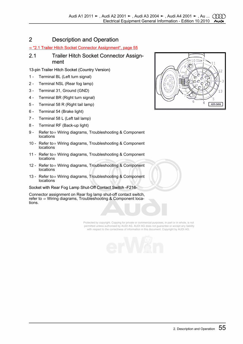
Protected by copyright. Copying for private or commercial purposes, in part or in whole, is not permitted unless authorised by AUDI AG. AUDI AG does not guarantee or accept any liability with respect to the correctness of information in this document. Copyright by AUDI AG.
2 Description and Operation⇒ “2.1 Trailer Hitch Socket Connector Assignment“, page 55
2.1 Trailer Hitch Socket Connector Assign‐ment
13-pin Trailer Hitch Socket (Country Version)1 - Terminal BL (Left turn signal)2 - Terminal NSL (Rear fog lamp)3 - Terminal 31, Ground (GND)4 - Terminal BR (Right turn signal)5 - Terminal 58 R (Right tail lamp)6 - Terminal 54 (Brake light)7 - Terminal 58 L (Left tail lamp)8 - Terminal RF (Back-up light)9 - Refer to⇒ Wiring diagrams, Troubleshooting & Component
locations10 - Refer to⇒ Wiring diagrams, Troubleshooting & Component
locations11 - Refer to⇒ Wiring diagrams, Troubleshooting & Component
locations12 - Refer to⇒ Wiring diagrams, Troubleshooting & Component
locations13 - Refer to⇒ Wiring diagrams, Troubleshooting & Component
locationsSocket with Rear Fog Lamp Shut-Off Contact Switch -F216-Connector assignment on Rear fog lamp shut-off contact switch,refer to ⇒ Wiring diagrams, Troubleshooting & Component loca‐tions.
Audi A1 2011 ➤ , Audi A2 2001 ➤ , Audi A3 2004 ➤ , Audi A4 2001 ➤ , Au ...Electrical Equipment General Information - Edition 10.2010
2. Description and Operation 55
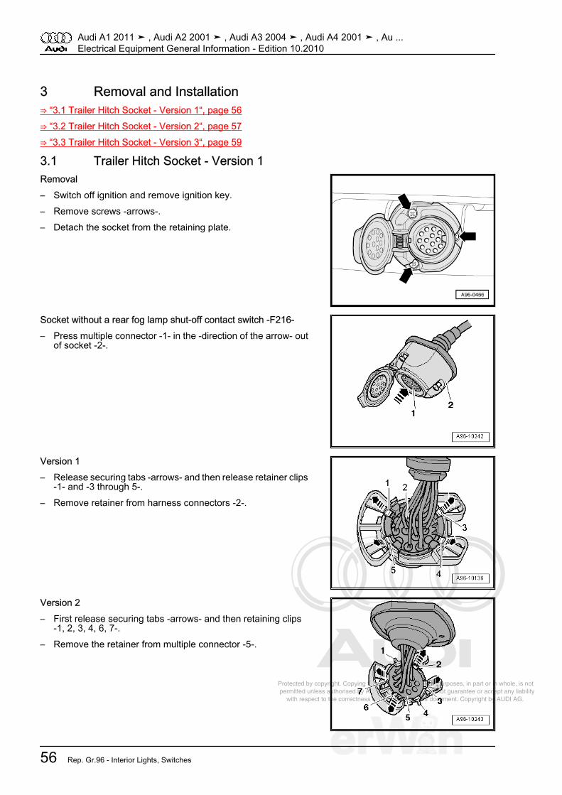
Protected by copyright. Copying for private or commercial purposes, in part or in whole, is not permitted unless authorised by AUDI AG. AUDI AG does not guarantee or accept any liability with respect to the correctness of information in this document. Copyright by AUDI AG.
3 Removal and Installation⇒ “3.1 Trailer Hitch Socket - Version 1“, page 56⇒ “3.2 Trailer Hitch Socket - Version 2“, page 57⇒ “3.3 Trailer Hitch Socket - Version 3“, page 59
3.1 Trailer Hitch Socket - Version 1Removal– Switch off ignition and remove ignition key.– Remove screws -arrows-.– Detach the socket from the retaining plate.
Socket without a rear fog lamp shut-off contact switch -F216-– Press multiple connector -1- in the -direction of the arrow- out
of socket -2-.
Version 1– Release securing tabs -arrows- and then release retainer clips
-1- and -3 through 5-.– Remove retainer from harness connectors -2-.
Version 2– First release securing tabs -arrows- and then retaining clips
-1, 2, 3, 4, 6, 7-.– Remove the retainer from multiple connector -5-.
Audi A1 2011 ➤ , Audi A2 2001 ➤ , Audi A3 2004 ➤ , Audi A4 2001 ➤ , Au ...Electrical Equipment General Information - Edition 10.2010
56 Rep. Gr.96 - Interior Lights, Switches
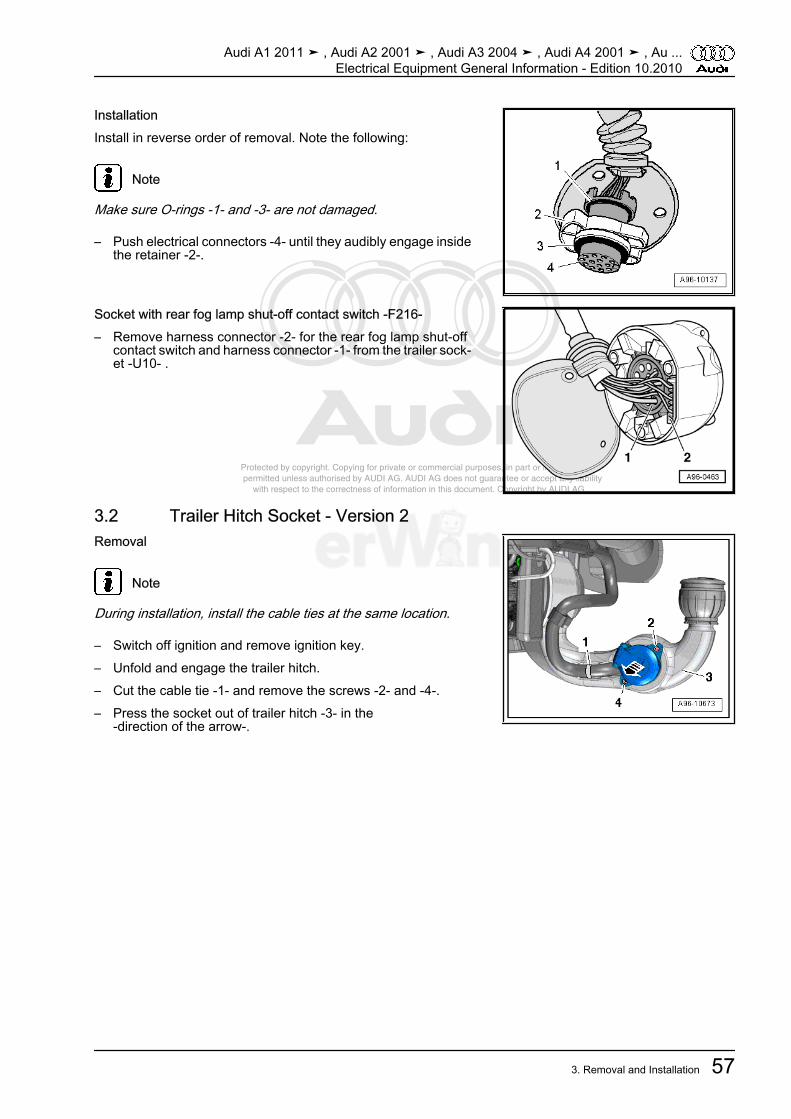
Protected by copyright. Copying for private or commercial purposes, in part or in whole, is not permitted unless authorised by AUDI AG. AUDI AG does not guarantee or accept any liability with respect to the correctness of information in this document. Copyright by AUDI AG.
InstallationInstall in reverse order of removal. Note the following:
Note
Make sure O-rings -1- and -3- are not damaged.
– Push electrical connectors -4- until they audibly engage insidethe retainer -2-.
Socket with rear fog lamp shut-off contact switch -F216-– Remove harness connector -2- for the rear fog lamp shut-off
contact switch and harness connector -1- from the trailer sock‐et -U10- .
3.2 Trailer Hitch Socket - Version 2Removal
Note
During installation, install the cable ties at the same location.
– Switch off ignition and remove ignition key.– Unfold and engage the trailer hitch.– Cut the cable tie -1- and remove the screws -2- and -4-.– Press the socket out of trailer hitch -3- in the
-direction of the arrow-.
Audi A1 2011 ➤ , Audi A2 2001 ➤ , Audi A3 2004 ➤ , Audi A4 2001 ➤ , Au ...Electrical Equipment General Information - Edition 10.2010
3. Removal and Installation 57

Protected by copyright. Copying for private or commercial purposes, in part or in whole, is not permitted unless authorised by AUDI AG. AUDI AG does not guarantee or accept any liability with respect to the correctness of information in this document. Copyright by AUDI AG.
– Turn cap -1- counterclockwise -arrow- and remove it fromsocket -3-.
– Remove rubber cover -2-.
– Release the retaining clips -arrows- and press multiple con‐nector -2- out of socket -1-.
– Release the retaining clips -arrows- and remove retainer -1-from multiple connector -3-.
Note
Carefully remove the retainer so that contacts -2- of the multipleconnector are not disconnected from the wiring harness.
Audi A1 2011 ➤ , Audi A2 2001 ➤ , Audi A3 2004 ➤ , Audi A4 2001 ➤ , Au ...Electrical Equipment General Information - Edition 10.2010
58 Rep. Gr.96 - Interior Lights, Switches
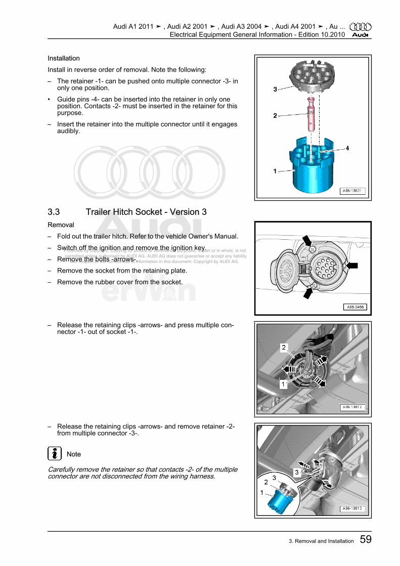
Protected by copyright. Copying for private or commercial purposes, in part or in whole, is not permitted unless authorised by AUDI AG. AUDI AG does not guarantee or accept any liability with respect to the correctness of information in this document. Copyright by AUDI AG.
InstallationInstall in reverse order of removal. Note the following:– The retainer -1- can be pushed onto multiple connector -3- in
only one position.• Guide pins -4- can be inserted into the retainer in only one
position. Contacts -2- must be inserted in the retainer for thispurpose.
– Insert the retainer into the multiple connector until it engagesaudibly.
3.3 Trailer Hitch Socket - Version 3Removal– Fold out the trailer hitch. Refer to the vehicle Owner's Manual.– Switch off the ignition and remove the ignition key.– Remove the bolts -arrows-.– Remove the socket from the retaining plate.– Remove the rubber cover from the socket.
– Release the retaining clips -arrows- and press multiple con‐nector -1- out of socket -1-.
– Release the retaining clips -arrows- and remove retainer -2-from multiple connector -3-.
Note
Carefully remove the retainer so that contacts -2- of the multipleconnector are not disconnected from the wiring harness.
Audi A1 2011 ➤ , Audi A2 2001 ➤ , Audi A3 2004 ➤ , Audi A4 2001 ➤ , Au ...Electrical Equipment General Information - Edition 10.2010
3. Removal and Installation 59
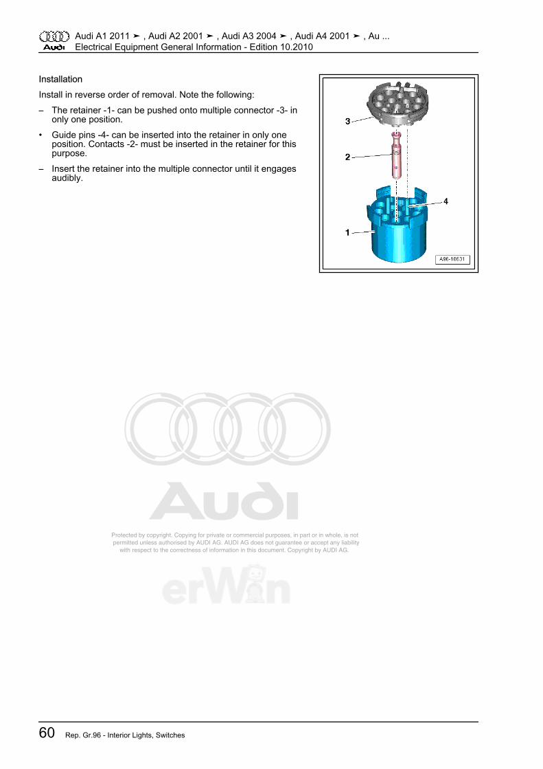
Protected by copyright. Copying for private or commercial purposes, in part or in whole, is not permitted unless authorised by AUDI AG. AUDI AG does not guarantee or accept any liability with respect to the correctness of information in this document. Copyright by AUDI AG.
InstallationInstall in reverse order of removal. Note the following:– The retainer -1- can be pushed onto multiple connector -3- in
only one position.• Guide pins -4- can be inserted into the retainer in only one
position. Contacts -2- must be inserted in the retainer for thispurpose.
– Insert the retainer into the multiple connector until it engagesaudibly.
Audi A1 2011 ➤ , Audi A2 2001 ➤ , Audi A3 2004 ➤ , Audi A4 2001 ➤ , Au ...Electrical Equipment General Information - Edition 10.2010
60 Rep. Gr.96 - Interior Lights, Switches

Protected by copyright. Copying for private or commercial purposes, in part or in whole, is not permitted unless authorised by AUDI AG. AUDI AG does not guarantee or accept any liability with respect to the correctness of information in this document. Copyright by AUDI AG.
97 – Wiring1 General Information⇒ “1.1 Antenna Wires, Repairing“, page 61⇒ “1.2 Fiber Optic Cable“, page 62⇒ “1.3 Connector Housings and Connectors, Repairing“,page 68⇒ “1.4 Contact Housings, Releasing and Disassembling“,page 71⇒ “1.5 Cleaning contact surfaces with the contact surface clean‐ing set VAS 6410 “, page 78⇒ “1.6 Vehicle Diagnosis, Testing and Information Systems“,page 84⇒ “1.7 Wiring Harnesses and Connectors, Repairing“,page 86
1.1 Antenna Wires, RepairingA repair procedure has been developed for repairing antennawires. Instead of a complete antenna wire, connecting wires ofdifferent lengths and various adapter leads are now available asreplacement parts.Replacement parts, refer to Electronic Parts Catalog; SpecialCatalog “Electrical Connection Elements“; Accessories; Sub‐group 35 chart 035-20.
Note
♦ Do not repair antenna wires. Replace them using connectorand adapter wires available as original replacement parts.
♦ These original replacement parts are suitable for all antennawires and wire cross sections that need to be replaced.
♦ Individual antenna connectors are not designed to be re‐placed.
♦ The wires must be used retroactively for all Audi models, forall installed antenna wire diameters.
♦ All adapter leads and connecting wires are suitable for varioustransmission and reception signals.
♦ The repair concept can also be used as a testing or retrofittingsolution.
Audi A1 2011 ➤ , Audi A2 2001 ➤ , Audi A3 2004 ➤ , Audi A4 2001 ➤ , Au ...Electrical Equipment General Information - Edition 10.2010
1. General Information 61

Protected by copyright. Copying for private or commercial purposes, in part or in whole, is not permitted unless authorised by AUDI AG. AUDI AG does not guarantee or accept any liability with respect to the correctness of information in this document. Copyright by AUDI AG.
Special tools and workshop equipment required-1- Adapter wire, for connection to radio; length: approximately 30cm-2- Connecting wire, available in various lengths-3- Adapter wire, for connection to antenna; length: approximately30 cmProcedureExample: Antenna wire from radio to antenna is faulty.– Separate the connectors of the faulty antenna wiring from their
components.– Determine the path of the faulty antenna wire in the vehicle
and measure the total length of antenna wire to be replaced.
• The entire length of the antenna wire consists of the length ofthe required adapter wires -1 and 3- and the connecting wire-2-.
– Subtract 60 cm from the total length of antenna wire meas‐ured, to receive the length of connecting wire required.
– Obtain the correct length of the required adapter wires andconnecting wires as an original replacement part. Refer toElectronic Parts Catalog (ETKA).
– Cut the connectors off of the faulty antenna wiring.• Leave the rest of the defective antenna wire in the vehicle.– Connect the adapter wires to the devices in the vehicle.– Provide harness connectors with piece of foam hose to avoid
rattle.– Route and secure connecting wire parallel to old antenna wire.
Note
Antenna wires must not be kinked or excessively bent! The bend‐ing radius must never be below 50 mm.
– Connect the connecting wire with the adapter leads.– To avoid rattle, slide a suitable piece of foam hose onto an‐
tenna connector.– Perform a function test.
1.2 Fiber Optic Cable⇒ “1.2.1 Repairing“, page 62⇒ “1.2.2 Disconnecting From Wiring Harness Connector“,page 66
1.2.1 RepairingSpecial tools and workshop equipment required♦ Fiber Optic Pliers Repair Set -VAS 6223-♦ Air Hose Pliers -VAS 6228-
Audi A1 2011 ➤ , Audi A2 2001 ➤ , Audi A3 2004 ➤ , Audi A4 2001 ➤ , Au ...Electrical Equipment General Information - Edition 10.2010
62 Rep. Gr.97 - Wiring

Protected by copyright. Copying for private or commercial purposes, in part or in whole, is not permitted unless authorised by AUDI AG. AUDI AG does not guarantee or accept any liability with respect to the correctness of information in this document. Copyright by AUDI AG.
Caution
Do not excessively bend or kink fiber optic cables. (minimumbending radius 25 mm).
Checking Remaining Cut Indicator– Start by checking remaining cut indicator:♦ The -VAS 6223/1- cutting device can perform approximately
1260 cuts. The blade is rotated for each additional cut.♦ The last remaining 150 cuts are indicated via the remaining
cut display -arrow-.♦ Once no further cuts are available, the blade is blocked. It must
be replaced. Refer to the Operating Instructions that come with-VAS 6223/1- .
Preparing Pliers For Fiber-Optic Conductor -VAS 6223/1-– Release transport safety device on cutter by loosening hex
socket bolt -arrow-.
Fiber Optic Cable, Cutting To Length– Establish length of fiber optic cable required.– Open -VAS 6223/1- and insert fiber-optic cable -1- into trim‐
ming station.– Close cutting tool to cut fiber optic cable to length.
Stripping– Open -VAS 6223/1- .• Stripping lever must be located in the lower position -arrow-.– Insert fiber-optic cable -1- into stripping station.• Fiber-optic cable must terminate flush to rear side of cutting
pliers.
Audi A1 2011 ➤ , Audi A2 2001 ➤ , Audi A3 2004 ➤ , Audi A4 2001 ➤ , Au ...Electrical Equipment General Information - Edition 10.2010
1. General Information 63
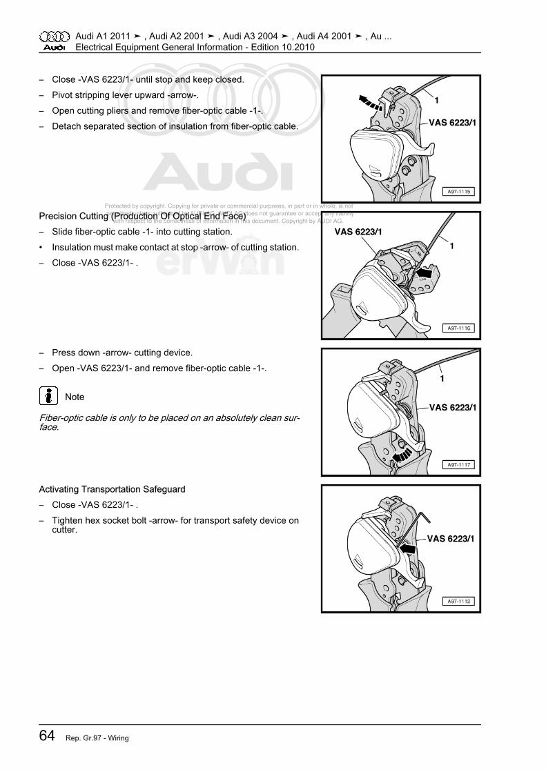
Protected by copyright. Copying for private or commercial purposes, in part or in whole, is not permitted unless authorised by AUDI AG. AUDI AG does not guarantee or accept any liability with respect to the correctness of information in this document. Copyright by AUDI AG.
– Close -VAS 6223/1- until stop and keep closed.– Pivot stripping lever upward -arrow-.– Open cutting pliers and remove fiber-optic cable -1-.– Detach separated section of insulation from fiber-optic cable.
Precision Cutting (Production Of Optical End Face)– Slide fiber-optic cable -1- into cutting station.• Insulation must make contact at stop -arrow- of cutting station.– Close -VAS 6223/1- .
– Press down -arrow- cutting device.– Open -VAS 6223/1- and remove fiber-optic cable -1-.
Note
Fiber-optic cable is only to be placed on an absolutely clean sur‐face.
Activating Transportation Safeguard– Close -VAS 6223/1- .– Tighten hex socket bolt -arrow- for transport safety device on
cutter.
Audi A1 2011 ➤ , Audi A2 2001 ➤ , Audi A3 2004 ➤ , Audi A4 2001 ➤ , Au ...Electrical Equipment General Information - Edition 10.2010
64 Rep. Gr.97 - Wiring
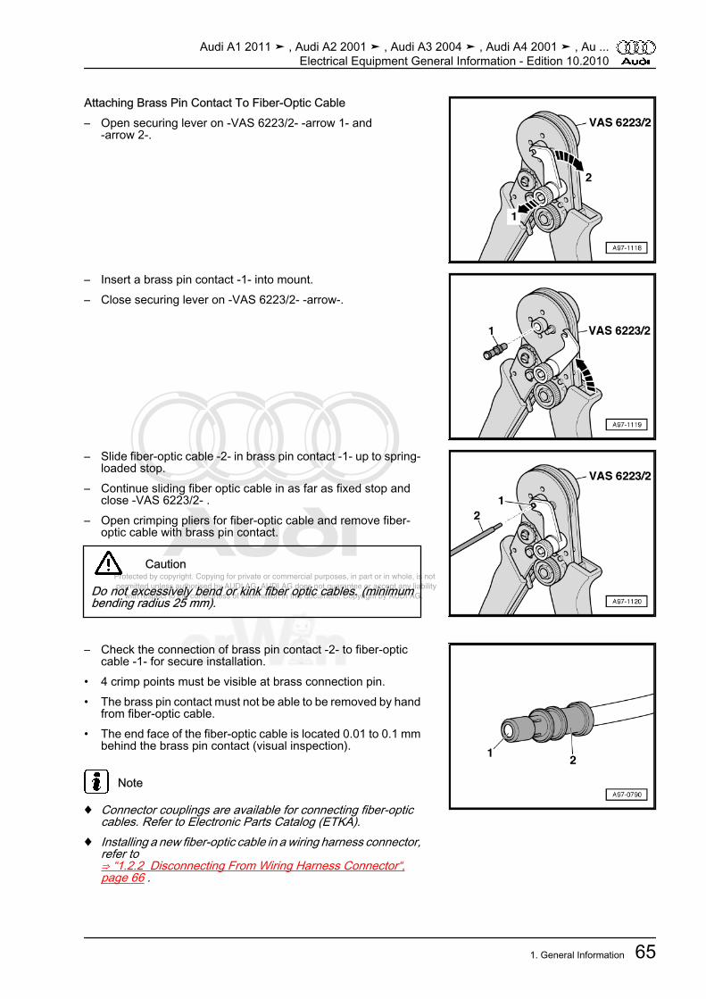
Protected by copyright. Copying for private or commercial purposes, in part or in whole, is not permitted unless authorised by AUDI AG. AUDI AG does not guarantee or accept any liability with respect to the correctness of information in this document. Copyright by AUDI AG.
Attaching Brass Pin Contact To Fiber-Optic Cable– Open securing lever on -VAS 6223/2- -arrow 1- and
-arrow 2-.
– Insert a brass pin contact -1- into mount.– Close securing lever on -VAS 6223/2- -arrow-.
– Slide fiber-optic cable -2- in brass pin contact -1- up to spring-loaded stop.
– Continue sliding fiber optic cable in as far as fixed stop andclose -VAS 6223/2- .
– Open crimping pliers for fiber-optic cable and remove fiber-optic cable with brass pin contact.
Caution
Do not excessively bend or kink fiber optic cables. (minimumbending radius 25 mm).
– Check the connection of brass pin contact -2- to fiber-opticcable -1- for secure installation.
• 4 crimp points must be visible at brass connection pin.• The brass pin contact must not be able to be removed by hand
from fiber-optic cable.• The end face of the fiber-optic cable is located 0.01 to 0.1 mm
behind the brass pin contact (visual inspection).
Note
♦ Connector couplings are available for connecting fiber-opticcables. Refer to Electronic Parts Catalog (ETKA).
♦ Installing a new fiber-optic cable in a wiring harness connector,refer to⇒ “1.2.2 Disconnecting From Wiring Harness Connector“,page 66 .
Audi A1 2011 ➤ , Audi A2 2001 ➤ , Audi A3 2004 ➤ , Audi A4 2001 ➤ , Au ...Electrical Equipment General Information - Edition 10.2010
1. General Information 65
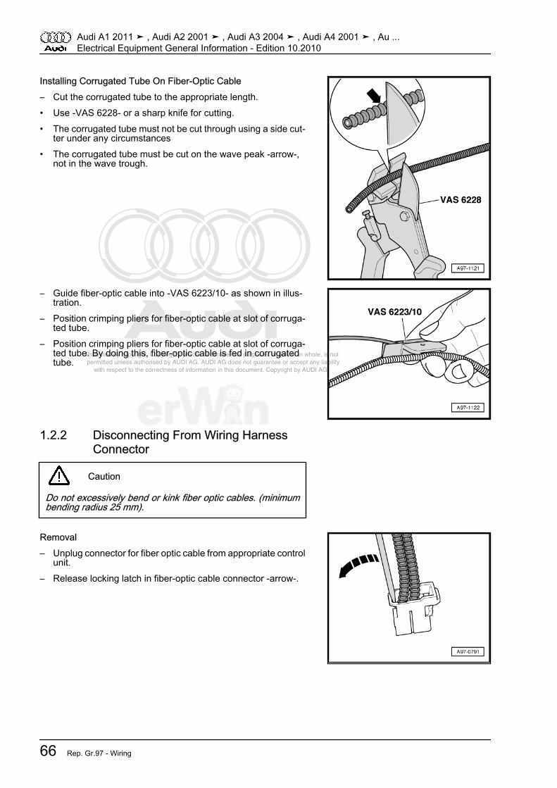
Protected by copyright. Copying for private or commercial purposes, in part or in whole, is not permitted unless authorised by AUDI AG. AUDI AG does not guarantee or accept any liability with respect to the correctness of information in this document. Copyright by AUDI AG.
Installing Corrugated Tube On Fiber-Optic Cable– Cut the corrugated tube to the appropriate length.• Use -VAS 6228- or a sharp knife for cutting.• The corrugated tube must not be cut through using a side cut‐
ter under any circumstances• The corrugated tube must be cut on the wave peak -arrow-,
not in the wave trough.
– Guide fiber-optic cable into -VAS 6223/10- as shown in illus‐tration.
– Position crimping pliers for fiber-optic cable at slot of corruga‐ted tube.
– Position crimping pliers for fiber-optic cable at slot of corruga‐ted tube. By doing this, fiber-optic cable is fed in corrugatedtube.
1.2.2 Disconnecting From Wiring HarnessConnector
Caution
Do not excessively bend or kink fiber optic cables. (minimumbending radius 25 mm).
Removal– Unplug connector for fiber optic cable from appropriate control
unit.– Release locking latch in fiber-optic cable connector -arrow-.
Audi A1 2011 ➤ , Audi A2 2001 ➤ , Audi A3 2004 ➤ , Audi A4 2001 ➤ , Au ...Electrical Equipment General Information - Edition 10.2010
66 Rep. Gr.97 - Wiring
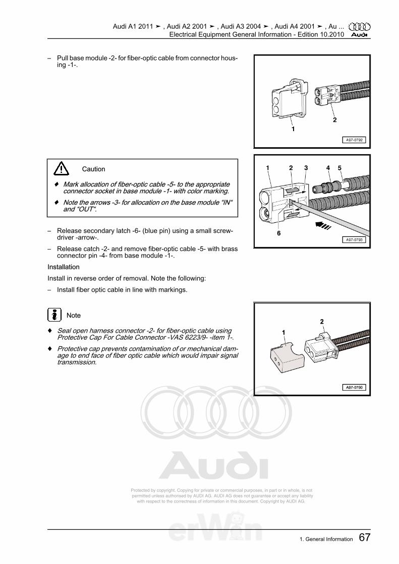
Protected by copyright. Copying for private or commercial purposes, in part or in whole, is not permitted unless authorised by AUDI AG. AUDI AG does not guarantee or accept any liability with respect to the correctness of information in this document. Copyright by AUDI AG.
– Pull base module -2- for fiber-optic cable from connector hous‐ing -1-.
Caution
♦ Mark allocation of fiber-optic cable -5- to the appropriateconnector socket in base module -1- with color marking.
♦ Note the arrows -3- for allocation on the base module “IN“and “OUT“.
– Release secondary latch -6- (blue pin) using a small screw‐driver -arrow-.
– Release catch -2- and remove fiber-optic cable -5- with brassconnector pin -4- from base module -1-.
InstallationInstall in reverse order of removal. Note the following:– Install fiber optic cable in line with markings.
Note
♦ Seal open harness connector -2- for fiber-optic cable usingProtective Cap For Cable Connector -VAS 6223/9- -item 1-.
♦ Protective cap prevents contamination of or mechanical dam‐age to end face of fiber optic cable which would impair signaltransmission.
Audi A1 2011 ➤ , Audi A2 2001 ➤ , Audi A3 2004 ➤ , Audi A4 2001 ➤ , Au ...Electrical Equipment General Information - Edition 10.2010
1. General Information 67
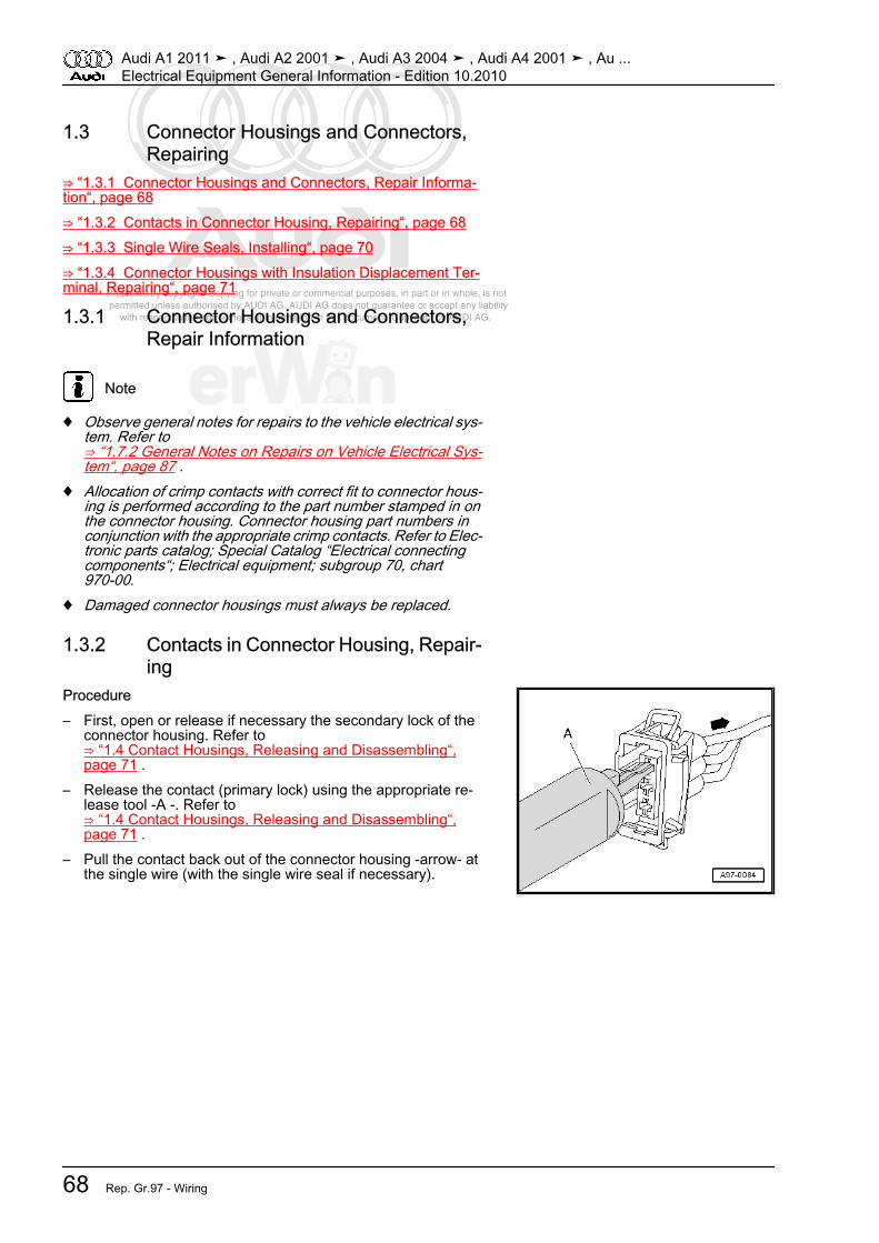
Protected by copyright. Copying for private or commercial purposes, in part or in whole, is not permitted unless authorised by AUDI AG. AUDI AG does not guarantee or accept any liability with respect to the correctness of information in this document. Copyright by AUDI AG.
1.3 Connector Housings and Connectors,Repairing
⇒ “1.3.1 Connector Housings and Connectors, Repair Informa‐tion“, page 68⇒ “1.3.2 Contacts in Connector Housing, Repairing“, page 68⇒ “1.3.3 Single Wire Seals, Installing“, page 70⇒ “1.3.4 Connector Housings with Insulation Displacement Ter‐minal, Repairing“, page 71
1.3.1 Connector Housings and Connectors,Repair Information
Note
♦ Observe general notes for repairs to the vehicle electrical sys‐tem. Refer to⇒ “1.7.2 General Notes on Repairs on Vehicle Electrical Sys‐tem“, page 87 .
♦ Allocation of crimp contacts with correct fit to connector hous‐ing is performed according to the part number stamped in onthe connector housing. Connector housing part numbers inconjunction with the appropriate crimp contacts. Refer to Elec‐tronic parts catalog; Special Catalog “Electrical connectingcomponents“; Electrical equipment; subgroup 70, chart970-00.
♦ Damaged connector housings must always be replaced.
1.3.2 Contacts in Connector Housing, Repair‐ing
Procedure– First, open or release if necessary the secondary lock of the
connector housing. Refer to⇒ “1.4 Contact Housings, Releasing and Disassembling“,page 71 .
– Release the contact (primary lock) using the appropriate re‐lease tool -A -. Refer to⇒ “1.4 Contact Housings, Releasing and Disassembling“,page 71 .
– Pull the contact back out of the connector housing -arrow- atthe single wire (with the single wire seal if necessary).
Audi A1 2011 ➤ , Audi A2 2001 ➤ , Audi A3 2004 ➤ , Audi A4 2001 ➤ , Au ...Electrical Equipment General Information - Edition 10.2010
68 Rep. Gr.97 - Wiring

Protected by copyright. Copying for private or commercial purposes, in part or in whole, is not permitted unless authorised by AUDI AG. AUDI AG does not guarantee or accept any liability with respect to the correctness of information in this document. Copyright by AUDI AG.
– Cut off the old contact (with the single wire seal) from the ve‐hicle-specific wiring harness.
– Take the yellow repair wire with the correct contact out of theWiring harness repair set -VAS 1978 B- .
– Free up the wire to be repaired approximately 20 cm on bothsides of the repair point.
Caution
Risk of damaging the electrical wires.♦ Expose wrapped wiring harnesses carefully.
– If necessary, removing the wiring harness wrapping using aknife.
– Slide the new repair wire contact into the corresponding con‐nector housing compartment until it engages.
– If necessary, install the single wire seal on the repair wire. Re‐fer to ⇒ “1.3.3 Single Wire Seals, Installing“, page 70 .
– Shorten the repair wire and the vehicle-specific wiring harnesssingle wire as needed using the Wire Stripper -VAS 1978/3- .
– Remove the insulation from the ends of the repair wire andvehicle-specific single wire and crimp the ends with the crimp‐ing wires and a crimp connector. Refer to⇒ “1.7.7 0.25 mm 2 Wire With Individual Crimp Connector,Repairing“, page 92 or⇒ “1.7.10 0.35 mm2 Or Greater With Intermediate Wire Sec‐tion, Repairing“, page 99 .
Audi A1 2011 ➤ , Audi A2 2001 ➤ , Audi A3 2004 ➤ , Audi A4 2001 ➤ , Au ...Electrical Equipment General Information - Edition 10.2010
1. General Information 69

Protected by copyright. Copying for private or commercial purposes, in part or in whole, is not permitted unless authorised by AUDI AG. AUDI AG does not guarantee or accept any liability with respect to the correctness of information in this document. Copyright by AUDI AG.
1.3.3 Single Wire Seals, InstallingProcedure
Note
♦ Single wire seals prevent the penetration of water and dirt intothe connector housing. They are installed e.g. in engine com‐partment and must be reinstalled after a repair.
♦ Single wire seal is crimped on at the factory together with con‐tact on the wire, this is not the case for repair wires. The singlewire seal must be slid onto the wire before crimping the repairwire.
♦ Single wire seals must always fit with the repair wire cross-section. Outer circumference of single wire seal is alignedaccording to chamber circumference of the connector hous‐ing. Perform assembly using only the assembly tool with cor‐rect fit.
– Put single wire seal -A- onto free end of repair wire.• When doing this, the single wire seal small diameter must point
toward the connector housing.
– Slide the single wire seal -A- onto the repair wire up to theconnector housing and then into the housing as far as the stopusing the appropriate assembly tool -B-.
Audi A1 2011 ➤ , Audi A2 2001 ➤ , Audi A3 2004 ➤ , Audi A4 2001 ➤ , Au ...Electrical Equipment General Information - Edition 10.2010
70 Rep. Gr.97 - Wiring

Protected by copyright. Copying for private or commercial purposes, in part or in whole, is not permitted unless authorised by AUDI AG. AUDI AG does not guarantee or accept any liability with respect to the correctness of information in this document. Copyright by AUDI AG.
1.3.4 Connector Housings with Insulation Dis‐placement Terminal, Repairing
Note
♦ For technical reasons, connector housings with insulation dis‐placement can be supplied only with the insulation displace‐ment contacts pushed in.
♦ If these contacts are not needed, they can be removed as onany other connector housing.
♦ Repair wires that already have the corresponding contactscrimped on are available. Refer to Electronic Parts Catalog(ETKA).
1.4 Contact Housings, Releasing and Dis‐assembling
⇒ “1.4.1 Releasing and Disassembling Connector Housings,General Information“, page 71⇒ “1.4.2 Secondary Lock“, page 72⇒ “1.4.3 Primary Lock“, page 73⇒ “1.4.4 Primary Connector With Round Connector Systems“,page 73⇒ “1.4.5 Primary Connector With Flat Connector Systems“, page74⇒ “1.4.6 Primary Connector With Special Connector Systems“,page 76
1.4.1 Releasing and Disassembling Connec‐tor Housings, General Information
WARNING
Risk of injury.♦ Some tools are supplied with a tool safety clip, which is
slid over the tool points after using the tool, in order toprotect other workers from injuries and tool points fromdamage.
Audi A1 2011 ➤ , Audi A2 2001 ➤ , Audi A3 2004 ➤ , Audi A4 2001 ➤ , Au ...Electrical Equipment General Information - Edition 10.2010
1. General Information 71
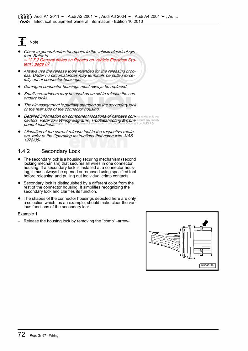
Protected by copyright. Copying for private or commercial purposes, in part or in whole, is not permitted unless authorised by AUDI AG. AUDI AG does not guarantee or accept any liability with respect to the correctness of information in this document. Copyright by AUDI AG.
Note
♦ Observe general notes for repairs to the vehicle electrical sys‐tem. Refer to⇒ “1.7.2 General Notes on Repairs on Vehicle Electrical Sys‐tem“, page 87 .
♦ Always use the release tools intended for the releasing proc‐ess. Under no circumstances may terminals be pulled force‐fully out of connector housings.
♦ Damaged connector housings must always be replaced.♦ Small screwdrivers may be used as an aid to release the sec‐
ondary locks.♦ The pin assignment is partially stamped on the secondary lock
or the rear side of the connector housing.♦ Detailed information on component locations of harness con‐
nectors. Refer to⇒ Wiring diagrams, Troubleshooting & Com‐ponent locations.
♦ Allocation of the correct release tool to the respective retain‐ers, refer to the Operating Instructions that come with -VAS1978/35- .
1.4.2 Secondary Lock♦ The secondary lock is a housing securing mechanism (second
locking mechanism) that secures all wires in one connectorhousing. If a secondary lock is installed at a connector hous‐ing, it must always be opened or removed using specified toolbefore releasing and pulling out individual crimp contacts.
♦ Secondary lock is distinguished by a different color from therest of the connector housing. It simplifies recognizing thesecondary lock and clarifies its function.
♦ The shapes of the connector housings depicted here are onlya selection which, as an example, should make clear the var‐ious functions of the secondary lock.
Example 1– Release the housing lock by removing the “comb“ -arrow-.
Audi A1 2011 ➤ , Audi A2 2001 ➤ , Audi A3 2004 ➤ , Audi A4 2001 ➤ , Au ...Electrical Equipment General Information - Edition 10.2010
72 Rep. Gr.97 - Wiring
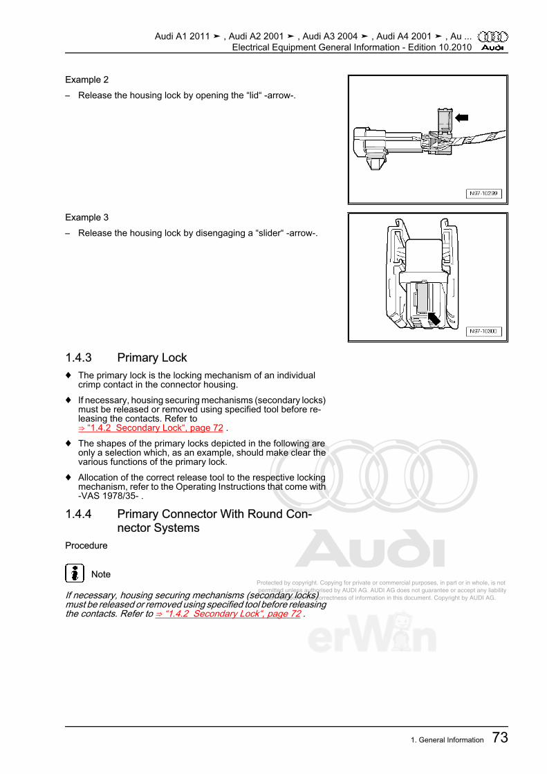
Protected by copyright. Copying for private or commercial purposes, in part or in whole, is not permitted unless authorised by AUDI AG. AUDI AG does not guarantee or accept any liability with respect to the correctness of information in this document. Copyright by AUDI AG.
Example 2– Release the housing lock by opening the “lid“ -arrow-.
Example 3– Release the housing lock by disengaging a “slider“ -arrow-.
1.4.3 Primary Lock♦ The primary lock is the locking mechanism of an individual
crimp contact in the connector housing.♦ If necessary, housing securing mechanisms (secondary locks)
must be released or removed using specified tool before re‐leasing the contacts. Refer to⇒ “1.4.2 Secondary Lock“, page 72 .
♦ The shapes of the primary locks depicted in the following areonly a selection which, as an example, should make clear thevarious functions of the primary lock.
♦ Allocation of the correct release tool to the respective lockingmechanism, refer to the Operating Instructions that come with-VAS 1978/35- .
1.4.4 Primary Connector With Round Con‐nector Systems
Procedure
Note
If necessary, housing securing mechanisms (secondary locks)must be released or removed using specified tool before releasingthe contacts. Refer to ⇒ “1.4.2 Secondary Lock“, page 72 .
Audi A1 2011 ➤ , Audi A2 2001 ➤ , Audi A3 2004 ➤ , Audi A4 2001 ➤ , Au ...Electrical Equipment General Information - Edition 10.2010
1. General Information 73
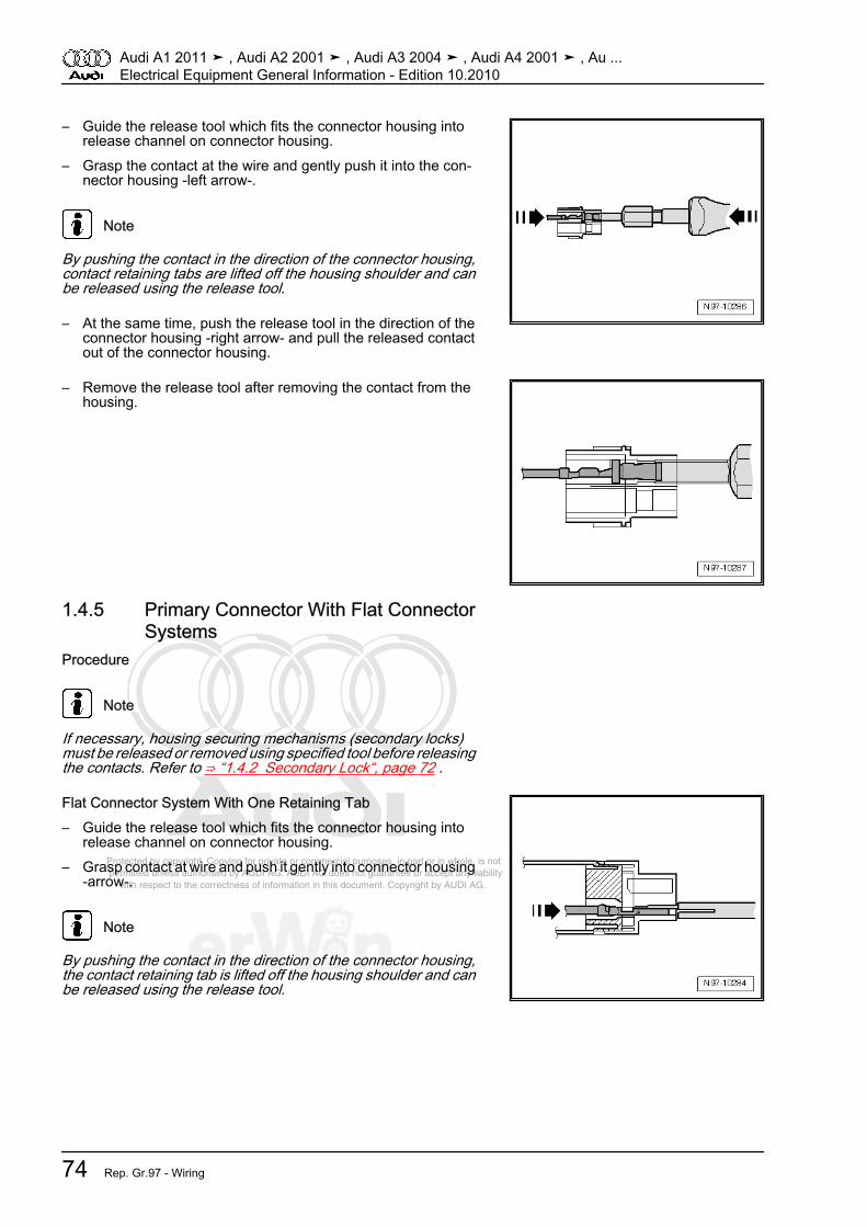
Protected by copyright. Copying for private or commercial purposes, in part or in whole, is not permitted unless authorised by AUDI AG. AUDI AG does not guarantee or accept any liability with respect to the correctness of information in this document. Copyright by AUDI AG.
– Guide the release tool which fits the connector housing intorelease channel on connector housing.
– Grasp the contact at the wire and gently push it into the con‐nector housing -left arrow-.
Note
By pushing the contact in the direction of the connector housing,contact retaining tabs are lifted off the housing shoulder and canbe released using the release tool.
– At the same time, push the release tool in the direction of theconnector housing -right arrow- and pull the released contactout of the connector housing.
– Remove the release tool after removing the contact from thehousing.
1.4.5 Primary Connector With Flat ConnectorSystems
Procedure
Note
If necessary, housing securing mechanisms (secondary locks)must be released or removed using specified tool before releasingthe contacts. Refer to ⇒ “1.4.2 Secondary Lock“, page 72 .
Flat Connector System With One Retaining Tab– Guide the release tool which fits the connector housing into
release channel on connector housing.– Grasp contact at wire and push it gently into connector housing
-arrow-.
Note
By pushing the contact in the direction of the connector housing,the contact retaining tab is lifted off the housing shoulder and canbe released using the release tool.
Audi A1 2011 ➤ , Audi A2 2001 ➤ , Audi A3 2004 ➤ , Audi A4 2001 ➤ , Au ...Electrical Equipment General Information - Edition 10.2010
74 Rep. Gr.97 - Wiring

Protected by copyright. Copying for private or commercial purposes, in part or in whole, is not permitted unless authorised by AUDI AG. AUDI AG does not guarantee or accept any liability with respect to the correctness of information in this document. Copyright by AUDI AG.
– At the same time, push the release tool in the direction of theconnector housing and pull the released contact out of theconnector housing -arrow-.
– Remove the release tool after removing the contact from thehousing.
Flat Connector System With Two Retaining Tabs– Guide the release tool which fits the connector housing into
release channel on connector housing.– Grasp contact at wire and push it gently into connector housing
until it stops -arrow-.
Note
By pushing the contact in the direction of the connector housing,contact retaining tabs are lifted off the housing shoulder and canbe released using the release tool.
– At the same time, push the release tool in the direction of theconnector housing and pull the released contact out of theconnector housing -arrow-.
– Remove the release tool after removing the contact from thehousing.
Asymmetrical– Guide the release tool which fits the connector housing into
release channel on connector housing.– Grasp contact at wire and push it gently into connector housing
-arrow-.
Note
By pushing the contact in the direction of the connector housing,contact retaining tabs are lifted off the housing shoulder and canbe released using the release tool.
Audi A1 2011 ➤ , Audi A2 2001 ➤ , Audi A3 2004 ➤ , Audi A4 2001 ➤ , Au ...Electrical Equipment General Information - Edition 10.2010
1. General Information 75
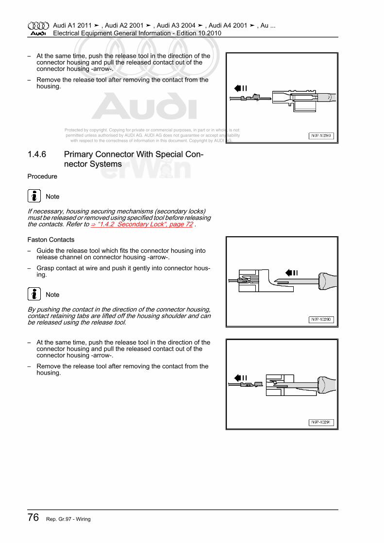
Protected by copyright. Copying for private or commercial purposes, in part or in whole, is not permitted unless authorised by AUDI AG. AUDI AG does not guarantee or accept any liability with respect to the correctness of information in this document. Copyright by AUDI AG.
– At the same time, push the release tool in the direction of theconnector housing and pull the released contact out of theconnector housing -arrow-.
– Remove the release tool after removing the contact from thehousing.
1.4.6 Primary Connector With Special Con‐nector Systems
Procedure
Note
If necessary, housing securing mechanisms (secondary locks)must be released or removed using specified tool before releasingthe contacts. Refer to ⇒ “1.4.2 Secondary Lock“, page 72 .
Faston Contacts– Guide the release tool which fits the connector housing into
release channel on connector housing -arrow-.– Grasp contact at wire and push it gently into connector hous‐
ing.
Note
By pushing the contact in the direction of the connector housing,contact retaining tabs are lifted off the housing shoulder and canbe released using the release tool.
– At the same time, push the release tool in the direction of theconnector housing and pull the released contact out of theconnector housing -arrow-.
– Remove the release tool after removing the contact from thehousing.
Audi A1 2011 ➤ , Audi A2 2001 ➤ , Audi A3 2004 ➤ , Audi A4 2001 ➤ , Au ...Electrical Equipment General Information - Edition 10.2010
76 Rep. Gr.97 - Wiring

Protected by copyright. Copying for private or commercial purposes, in part or in whole, is not permitted unless authorised by AUDI AG. AUDI AG does not guarantee or accept any liability with respect to the correctness of information in this document. Copyright by AUDI AG.
GT 150/280 Contacts– Guide the release tool which fits the connector housing under
retaining tab into connector housing.– Push tool into connector housing until it stops -arrow-.
• Contact is ejected from the connector housing.– Remove the release tool after removing the contact from the
housing.
Contacts Without Retaining Tabs– Insert release tool under retaining tab of connector housing.– Push release tool through until it stops by gently lifting
-arrow-.
• Contact is ejected from the connector housing.– Remove the release tool after removing the contact from the
housing.
Audi A1 2011 ➤ , Audi A2 2001 ➤ , Audi A3 2004 ➤ , Audi A4 2001 ➤ , Au ...Electrical Equipment General Information - Edition 10.2010
1. General Information 77
Protected by copyright. Copying for private or commercial purposes, in part or in whole, is not permitted unless authorised by AUDI AG. AUDI AG does not guarantee or accept any liability with respect to the correctness of information in this document. Copyright by AUDI AG.
1.5 Cleaning contact surfaces with the con‐tact surface cleaning set -VAS 6410-
⇒ “1.5.1 Wiring Eyelets, Servicing“, page 78⇒ “1.5.2 Threaded Connections, Servicing“, page 79⇒ “1.5.3 Battery Clamps and Terminals, Cleaning“, page 81⇒ “1.5.4 Protecting“, page 82
1.5.1 Wiring Eyelets, ServicingSpecial tools and workshop equipment required♦ Contact Surfaces Cleaning Set -VAS 6410-
Note
♦ Using the Contact surface cleaning set VAS 6410 -VAS 6410- ,service work can be performed in the area of the contact sen‐sor on the threaded connection wiring harnesses in the highcurrent circuit (starter and charging current).
♦ The gray sanding pads are for slight contamination and suit‐able for "soft surfaces". The red sanding pads are for heavycontamination and suitable for "hard surfaces".
Note
Do not use rust remover, contact spray or grease because thelack of friction will cause the torque to be exceeded when instal‐ling and this will lead to the threaded connection breaking.
WARNING
Risk of injury.♦ Follow all Warnings and Safety Precautions. Refer to
⇒ “1.5 Lead-Acid Battery Warnings and Safety Precau‐tions“, page 8 .
– Disconnect the battery. Refer to⇒ Electrical Equipment; Rep.Gr. 27 ; Removal and Installation .
Audi A1 2011 ➤ , Audi A2 2001 ➤ , Audi A3 2004 ➤ , Audi A4 2001 ➤ , Au ...Electrical Equipment General Information - Edition 10.2010
78 Rep. Gr.97 - Wiring

Protected by copyright. Copying for private or commercial purposes, in part or in whole, is not permitted unless authorised by AUDI AG. AUDI AG does not guarantee or accept any liability with respect to the correctness of information in this document. Copyright by AUDI AG.
– Loosen the cap nut and remove the wiring eyelet from thethreaded connection.
– Check the wiring eyelet for corrosion, contamination, etc.– Select the corresponding adapter and the corresponding
sanding pad.
Note
A sanding block can be used instead.
Caution
Increased corrosion due to an exposed copper layer.♦ Make sure the tin layer is not worn down too much and the
copper is not visible. Increased corrosion can result dueto the galvanizing effects.
Note
Due to the different thicknesses of the tin layer, the cleaning proc‐ess must be performed in several steps and a visual inspectionof the wiring eyelet between steps is necessary.
– Insert the adapter in the wiring eyelet and sand off the corro‐sion and contamination with circular motion.
– Check the wiring eyelet and sand it again if necessary.– If necessary, remove the burr on the wiring eyelet with the de‐
burrer.– Reinstall the wiring eyelet to the tightening specification.
Note
Optimal contact is ensured if the bolted components are tightenedto the specified torque after cleaning.
– Protect the connection with the corresponding protection ma‐terial. Refer to ⇒ “1.5.4 Protecting“, page 82 .
– Reconnect the battery. Refer to⇒ Electrical Equipment; Rep.Gr. 27 ; Removal and Installation .
1.5.2 Threaded Connections, ServicingSpecial tools and workshop equipment required♦ Contact Surfaces Cleaning Set -VAS 6410-
Audi A1 2011 ➤ , Audi A2 2001 ➤ , Audi A3 2004 ➤ , Audi A4 2001 ➤ , Au ...Electrical Equipment General Information - Edition 10.2010
1. General Information 79
Protected by copyright. Copying for private or commercial purposes, in part or in whole, is not permitted unless authorised by AUDI AG. AUDI AG does not guarantee or accept any liability with respect to the correctness of information in this document. Copyright by AUDI AG.
Note
♦ Using the Contact surface cleaning set VAS 6410 -VAS 6410- ,service work can be performed in the area of the contact sen‐sor on the threaded connection wiring harnesses in the highcurrent circuit (starter and charging current).
♦ The gray sanding pads are for slight contamination and suit‐able for "soft surfaces". The red sanding pads are for heavycontamination and suitable for "hard surfaces".
Note
Do not use rust remover, contact spray or grease because thelack of friction will cause the torque to be exceeded when instal‐ling and this will lead to the threaded connections breaking.
WARNING
Risk of injury.♦ Follow all Warnings and Safety Precautions. Refer to
⇒ “1.5 Lead-Acid Battery Warnings and Safety Precau‐tions“, page 8 .
– Disconnect the battery. Refer to⇒ Electrical Equipment; Rep.Gr. 27 ; Removal and Installation .
Audi A1 2011 ➤ , Audi A2 2001 ➤ , Audi A3 2004 ➤ , Audi A4 2001 ➤ , Au ...Electrical Equipment General Information - Edition 10.2010
80 Rep. Gr.97 - Wiring

Protected by copyright. Copying for private or commercial purposes, in part or in whole, is not permitted unless authorised by AUDI AG. AUDI AG does not guarantee or accept any liability with respect to the correctness of information in this document. Copyright by AUDI AG.
– Loosen the cap nut and remove the wiring eyelet from thethreaded connection.
– Check the threaded connection for corrosion, contamination,etc.
– Select the corresponding adapter and the correspondingsanding pad for the threaded connection.
Caution
Increased corrosion due to an exposed copper layer.♦ Make sure the tin layer is not worn down too much and the
copper is not visible. Increased corrosion can result dueto the galvanizing effects.
Note
Due to the different thicknesses of the tin layer, the cleaning proc‐ess must be performed in several steps and a visual inspectionof the threaded connection between steps is necessary.
– Insert the adapter in the threaded connection and sand off thecorrosion and contamination with circular motion.
– Check the threaded connection and sand it again if necessary.– Tighten the connection and, if necessary, the anti-rotation pro‐
tection to the tightening specification.
Note
Optimal contact is ensured if the bolted components are tightenedto the specified torque after cleaning.
– Protect the connection with the corresponding protection ma‐terial. Refer to ⇒ “1.5.4 Protecting“, page 82 .
– Reconnect the battery. Refer to⇒ Electrical Equipment; Rep.Gr. 27 ; Removal and Installation .
1.5.3 Battery Clamps and Terminals, Clean‐ing
Special tools and workshop equipment required♦ Contact Surfaces Cleaning Set -VAS 6410-
Note
♦ Using the Contact surface cleaning set VAS 6410 -VAS 6410- ,service work can be performed in the area of the contact sen‐sor on the threaded connection wiring harnesses in the highcurrent circuit (starter and charging current).
♦ The gray sanding pads are for slight contamination and suit‐able for "soft surfaces". The red sanding pads are for heavycontamination and suitable for "hard surfaces".
Audi A1 2011 ➤ , Audi A2 2001 ➤ , Audi A3 2004 ➤ , Audi A4 2001 ➤ , Au ...Electrical Equipment General Information - Edition 10.2010
1. General Information 81
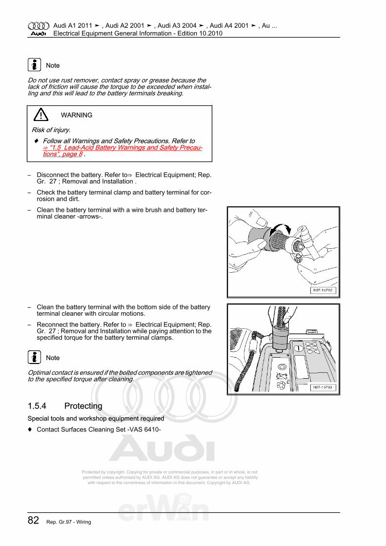
Protected by copyright. Copying for private or commercial purposes, in part or in whole, is not permitted unless authorised by AUDI AG. AUDI AG does not guarantee or accept any liability with respect to the correctness of information in this document. Copyright by AUDI AG.
Note
Do not use rust remover, contact spray or grease because thelack of friction will cause the torque to be exceeded when instal‐ling and this will lead to the battery terminals breaking.
WARNING
Risk of injury.♦ Follow all Warnings and Safety Precautions. Refer to
⇒ “1.5 Lead-Acid Battery Warnings and Safety Precau‐tions“, page 8 .
– Disconnect the battery. Refer to⇒ Electrical Equipment; Rep.Gr. 27 ; Removal and Installation .
– Check the battery terminal clamp and battery terminal for cor‐rosion and dirt.
– Clean the battery terminal with a wire brush and battery ter‐minal cleaner -arrows-.
– Clean the battery terminal with the bottom side of the batteryterminal cleaner with circular motions.
– Reconnect the battery. Refer to ⇒ Electrical Equipment; Rep.Gr. 27 ; Removal and Installation while paying attention to thespecified torque for the battery terminal clamps.
Note
Optimal contact is ensured if the bolted components are tightenedto the specified torque after cleaning.
1.5.4 ProtectingSpecial tools and workshop equipment required♦ Contact Surfaces Cleaning Set -VAS 6410-
Audi A1 2011 ➤ , Audi A2 2001 ➤ , Audi A3 2004 ➤ , Audi A4 2001 ➤ , Au ...Electrical Equipment General Information - Edition 10.2010
82 Rep. Gr.97 - Wiring
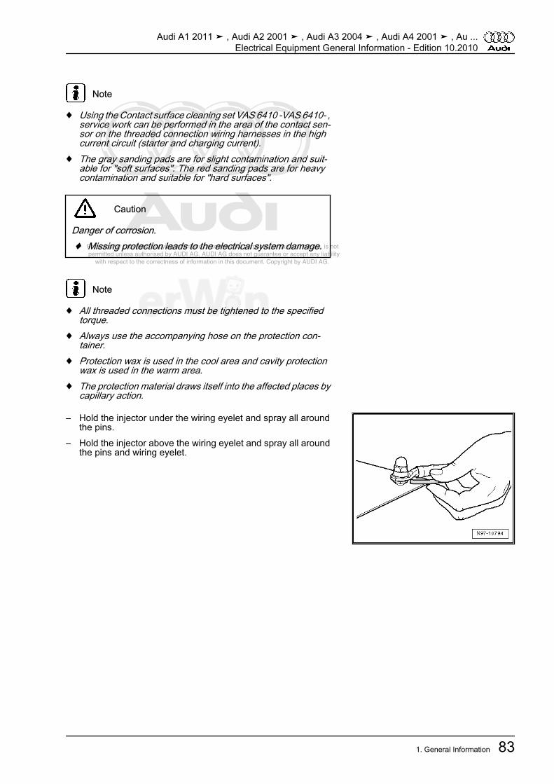
Protected by copyright. Copying for private or commercial purposes, in part or in whole, is not permitted unless authorised by AUDI AG. AUDI AG does not guarantee or accept any liability with respect to the correctness of information in this document. Copyright by AUDI AG.
Note
♦ Using the Contact surface cleaning set VAS 6410 -VAS 6410- ,service work can be performed in the area of the contact sen‐sor on the threaded connection wiring harnesses in the highcurrent circuit (starter and charging current).
♦ The gray sanding pads are for slight contamination and suit‐able for "soft surfaces". The red sanding pads are for heavycontamination and suitable for "hard surfaces".
Caution
Danger of corrosion.♦ Missing protection leads to the electrical system damage.
Note
♦ All threaded connections must be tightened to the specifiedtorque.
♦ Always use the accompanying hose on the protection con‐tainer.
♦ Protection wax is used in the cool area and cavity protectionwax is used in the warm area.
♦ The protection material draws itself into the affected places bycapillary action.
– Hold the injector under the wiring eyelet and spray all aroundthe pins.
– Hold the injector above the wiring eyelet and spray all aroundthe pins and wiring eyelet.
Audi A1 2011 ➤ , Audi A2 2001 ➤ , Audi A3 2004 ➤ , Audi A4 2001 ➤ , Au ...Electrical Equipment General Information - Edition 10.2010
1. General Information 83

Protected by copyright. Copying for private or commercial purposes, in part or in whole, is not permitted unless authorised by AUDI AG. AUDI AG does not guarantee or accept any liability with respect to the correctness of information in this document. Copyright by AUDI AG.
1.6 Vehicle Diagnosis, Testing and Informa‐tion Systems
⇒ “1.6.1 Application Information and Safety Precautions“,page 84⇒ “1.6.2 Connecting the Vehicle Diagnosis Tester“, page 85
1.6.1 Application Information and Safety Pre‐cautions
Audi A1, Audi A2, Audi A3, Audi A4, Audi A4 Cabriolet, Audi A5,Audi A6, Audi A7, Audi A8, Audi Q5, Audi Q7
WARNING
Distraction and inadequately secured measuring equipmentposes an accident risk.There is a risk due to deployment of the front passenger airbagin an accident.• Operating measuring equipment while driving creates a
distraction.• There is an increased risk of injury if measuring equipment
is not secured.♦ Always secure measuring equipment with a strap on the
rear seat and have a 2nd person in the rear seat operateit.
Audi TT and Audi R8
WARNING
Distraction and inadequately secured measuring equipmentposes an accident risk.There is a risk due to deployment of the front passenger airbagin an accident.• Operating measuring equipment while driving creates a
distraction.• There is an increased risk of injury if measuring equipment
is not secured.♦ Position the passenger's seat as far back as possible.♦ Only use the Vehicle Diagnosis and Service Information
System -VAS 5052 A- or Diagnostic system -VAS 5053- .♦ Measuring equipment -1- must lie flat on the passenger's
legs and be operated by that person, as shown in the il‐lustration.
Note
♦ The Vehicle Diagnosis Tester can perform all adaptations,coding, etc.
♦ All work instructions can be reached in the operating modes“Guided Fault Finding“ and “Guided Functions“.
Audi A1 2011 ➤ , Audi A2 2001 ➤ , Audi A3 2004 ➤ , Audi A4 2001 ➤ , Au ...Electrical Equipment General Information - Edition 10.2010
84 Rep. Gr.97 - Wiring
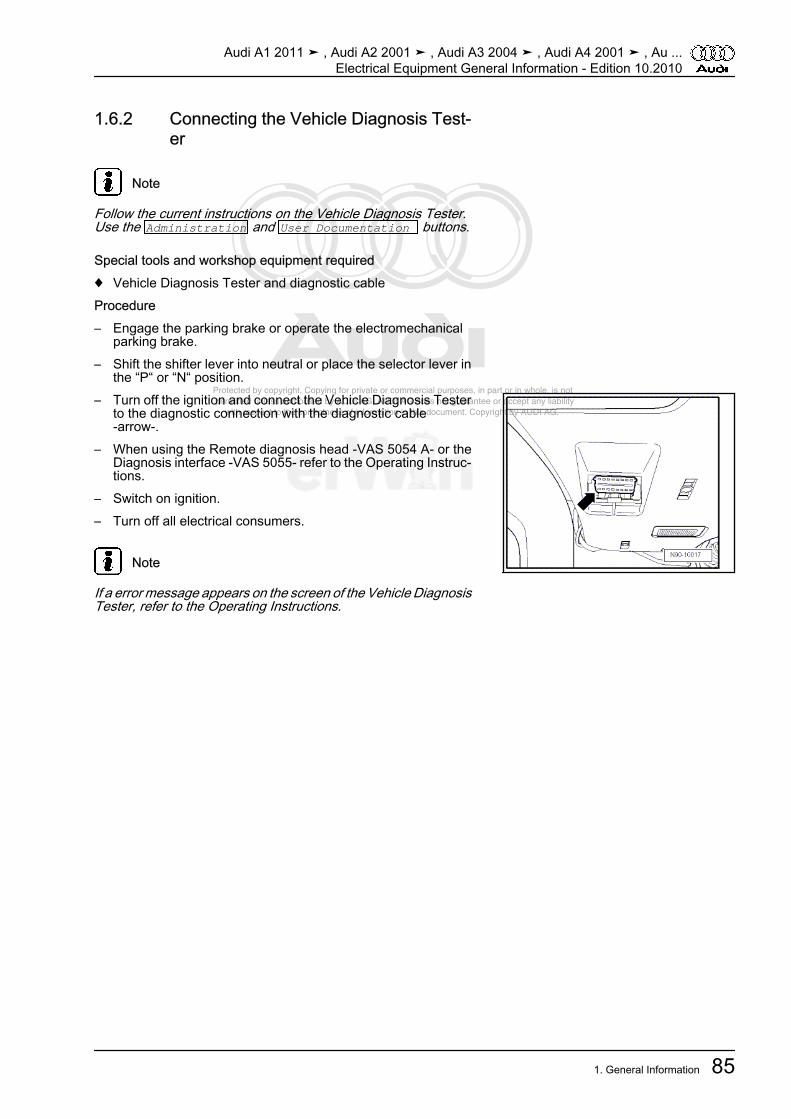
Protected by copyright. Copying for private or commercial purposes, in part or in whole, is not permitted unless authorised by AUDI AG. AUDI AG does not guarantee or accept any liability with respect to the correctness of information in this document. Copyright by AUDI AG.
1.6.2 Connecting the Vehicle Diagnosis Test‐er
Note
Follow the current instructions on the Vehicle Diagnosis Tester.Use the Administration and User Documentation buttons.
Special tools and workshop equipment required♦ Vehicle Diagnosis Tester and diagnostic cableProcedure– Engage the parking brake or operate the electromechanical
parking brake.– Shift the shifter lever into neutral or place the selector lever in
the “P“ or “N“ position.– Turn off the ignition and connect the Vehicle Diagnosis Tester
to the diagnostic connection with the diagnostic cable-arrow-.
– When using the Remote diagnosis head -VAS 5054 A- or theDiagnosis interface -VAS 5055- refer to the Operating Instruc‐tions.
– Switch on ignition.– Turn off all electrical consumers.
Note
If a error message appears on the screen of the Vehicle DiagnosisTester, refer to the Operating Instructions.
Audi A1 2011 ➤ , Audi A2 2001 ➤ , Audi A3 2004 ➤ , Audi A4 2001 ➤ , Au ...Electrical Equipment General Information - Edition 10.2010
1. General Information 85
Protected by copyright. Copying for private or commercial purposes, in part or in whole, is not permitted unless authorised by AUDI AG. AUDI AG does not guarantee or accept any liability with respect to the correctness of information in this document. Copyright by AUDI AG.
1.7 Wiring Harnesses and Connectors, Re‐pairing
⇒ “1.7.1 General Notes For Repairing Wiring Harnesses andConnectors“, page 86⇒ “1.7.2 General Notes on Repairs on Vehicle Electrical System“,page 87⇒ “1.7.3 Electro-Static Discharge Work Surface VAS 6613 “, page88⇒ “1.7.4 Pyrotechnic Component Wire, Repairing“, page 88⇒ “1.7.5 CAN Bus Wire, Repairing “, page 90⇒ “1.7.6 FlexRay Wire, Repairing“, page 91⇒ “1.7.7 0.25 mm 2 Wire With Individual Crimp Connector, Re‐pairing“, page 92⇒ “1.7.8 0.25 mm2 Wire With Intermediate Wire Section, Repair‐ing“, page 94⇒ “1.7.9 0.35 mm 2 Or Greater With Individual Crimp Connector,Repairing“, page 97⇒ “1.7.10 0.35 mm2 Or Greater With Intermediate Wire Section,Repairing“, page 99
1.7.1 General Notes For Repairing WiringHarnesses and Connectors
Note
♦ Observe general notes for repairs on the vehicle electricalsystem. Refer to⇒ “1.7.2 General Notes on Repairs on Vehicle Electrical Sys‐tem“, page 87 .
♦ The Wiring harness repair set -VAS 1978 B- does not containall the wire cross-sections in the vehicle. If the required wirecross-section is not present, the next greater cross-sectionmust be used.
♦ For repairs on the vehicle electrical system, soldering is notpermitted.
♦ Do not repair crimp connectors. If necessary, lay a wire parallelto the faulty wire.
♦ After crimping, crimp connections must be heat-shrunk usingthe hot air blower to prevent moisture penetration.
♦ Shielded wires such as for speed sensors and knock sensorsmay not be repaired. If faulty, the entire harness must be re‐placed.
♦ Exclusive use is to be made of yellow wires for wiring harnessrepairs.
♦ Wiring harness repairs should not be made again in the wrap‐ping on the vehicle-specific wiring harness.
♦ Mark repaired areas using yellow adhesive tape.♦ Yellow wires and areas in the wiring harness wrapped with
yellow adhesive tape mark a previously performed repair.♦ Perform a function test after each repair. If necessary, check
DTC memory, erase and/or bring systems into basic setting.
Audi A1 2011 ➤ , Audi A2 2001 ➤ , Audi A3 2004 ➤ , Audi A4 2001 ➤ , Au ...Electrical Equipment General Information - Edition 10.2010
86 Rep. Gr.97 - Wiring
Protected by copyright. Copying for private or commercial purposes, in part or in whole, is not permitted unless authorised by AUDI AG. AUDI AG does not guarantee or accept any liability with respect to the correctness of information in this document. Copyright by AUDI AG.
1.7.2 General Notes on Repairs on VehicleElectrical System
Special tools and workshop equipment required♦ Wiring Harness Repair Set VAS 1978/A -VAS 1978 B-
Caution
♦ Repairs to the wiring harnesses and connectors must onlybe performed using the Wiring harness repair set -VAS1978 B- .
♦ Observe the country-specific requirements.
Note
♦ Use of the Wiring harness repair set -VAS 1978 B- is describedin detail in the attached operating instructions.
♦ Repairs on open circuits and faulty connectors are also ex‐plained using examples.
WARNING
Risk of injury.♦ Pay attention to decals designating high voltage compo‐
nents. When performing repairs, residual voltage must bedischarged.
♦ Some tools are supplied with a tool safety clip, which isslid over the tool points after using the tool, in order toprotect other workers from injuries and tool points fromdamage.
Caution
♦ Observe the country-specific requirements.♦ By disconnecting the battery ground (GND) wire, safe
work on the vehicle electrical system is guaranteed. Withthe ignition switched off, disconnect the ground wire on thebattery. Refer to⇒ Electrical Equipment; Rep. Gr. 27 ;Removal and Installation .
♦ Before starting a repair, the cause of the damage must beeliminated first, such as, sharp edges on chassis parts,faulty electrical consumers, corrosion, etc.
Note
♦ If possible, do not loosen the ground (GND) straps from body(danger of corrosion).
♦ Further information relating for example to the removal andinstallation of individual components can be found in the ap‐propriate repair manual.
Audi A1 2011 ➤ , Audi A2 2001 ➤ , Audi A3 2004 ➤ , Audi A4 2001 ➤ , Au ...Electrical Equipment General Information - Edition 10.2010
1. General Information 87
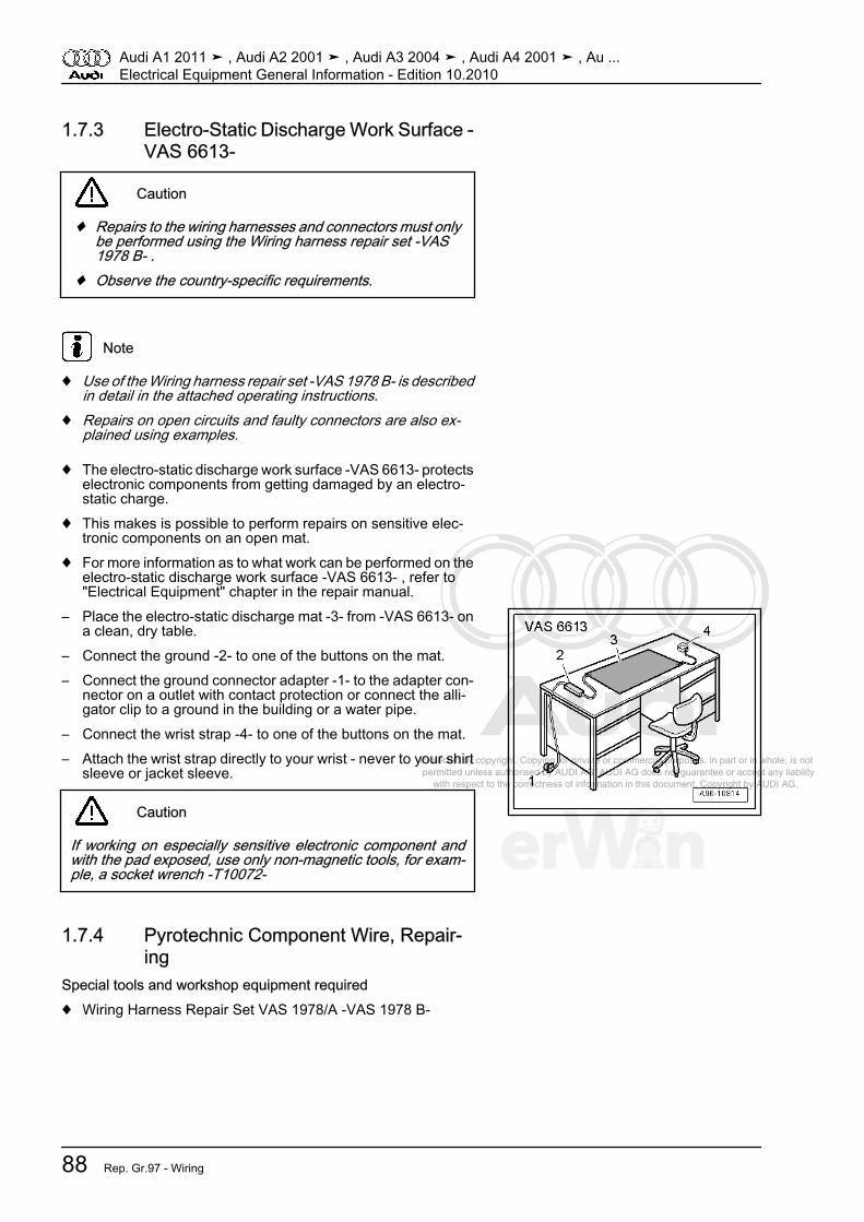
Protected by copyright. Copying for private or commercial purposes, in part or in whole, is not permitted unless authorised by AUDI AG. AUDI AG does not guarantee or accept any liability with respect to the correctness of information in this document. Copyright by AUDI AG.
1.7.3 Electro-Static Discharge Work Surface -VAS 6613-
Caution
♦ Repairs to the wiring harnesses and connectors must onlybe performed using the Wiring harness repair set -VAS1978 B- .
♦ Observe the country-specific requirements.
Note
♦ Use of the Wiring harness repair set -VAS 1978 B- is describedin detail in the attached operating instructions.
♦ Repairs on open circuits and faulty connectors are also ex‐plained using examples.
♦ The electro-static discharge work surface -VAS 6613- protectselectronic components from getting damaged by an electro-static charge.
♦ This makes is possible to perform repairs on sensitive elec‐tronic components on an open mat.
♦ For more information as to what work can be performed on theelectro-static discharge work surface -VAS 6613- , refer to"Electrical Equipment" chapter in the repair manual.
– Place the electro-static discharge mat -3- from -VAS 6613- ona clean, dry table.
– Connect the ground -2- to one of the buttons on the mat.– Connect the ground connector adapter -1- to the adapter con‐
nector on a outlet with contact protection or connect the alli‐gator clip to a ground in the building or a water pipe.
– Connect the wrist strap -4- to one of the buttons on the mat.– Attach the wrist strap directly to your wrist - never to your shirt
sleeve or jacket sleeve.
Caution
If working on especially sensitive electronic component andwith the pad exposed, use only non-magnetic tools, for exam‐ple, a socket wrench -T10072-
1.7.4 Pyrotechnic Component Wire, Repair‐ing
Special tools and workshop equipment required♦ Wiring Harness Repair Set VAS 1978/A -VAS 1978 B-
Audi A1 2011 ➤ , Audi A2 2001 ➤ , Audi A3 2004 ➤ , Audi A4 2001 ➤ , Au ...Electrical Equipment General Information - Edition 10.2010
88 Rep. Gr.97 - Wiring
Protected by copyright. Copying for private or commercial purposes, in part or in whole, is not permitted unless authorised by AUDI AG. AUDI AG does not guarantee or accept any liability with respect to the correctness of information in this document. Copyright by AUDI AG.
Caution
♦ Repairs to the wiring harnesses and connectors must onlybe performed using the Wiring harness repair set -VAS1978 B- .
♦ Observe the country-specific requirements.
Note
♦ Use of the Wiring harness repair set -VAS 1978 B- is describedin detail in the attached operating instructions.
♦ Repairs on open circuits and faulty connectors are also ex‐plained using examples.
Note
♦ Observe general notes for repairs on the vehicle electricalsystem. Refer to⇒ “1.7.2 General Notes on Repairs on Vehicle Electrical Sys‐tem“, page 87 .
♦ Observe the notes on wiring harness and connector repairs.Refer to⇒ “1.7.1 General Notes For Repairing Wiring Harnesses andConnectors“, page 86 including identifying repair locations.
WARNING
Passenger protection malfunction due to faulty repairs to thewires for pyrotechnic components - for example, airbag, belttensioner.♦ Repairs to wires for pyrotechnic components may only be
performed on the vehicle side using the Wiring harnessrepair set -VAS 1978 B- and original replacement parts(connector housing, contacts, wires) in order to guaranteethe repair quality required by Audi AG.
♦ Wires at individual airbag units may not be repaired.♦ If the wires or connectors on the airbag units are damaged,
the respective airbag unit must be replaced for safety rea‐sons.
Audi A1 2011 ➤ , Audi A2 2001 ➤ , Audi A3 2004 ➤ , Audi A4 2001 ➤ , Au ...Electrical Equipment General Information - Edition 10.2010
1. General Information 89

Protected by copyright. Copying for private or commercial purposes, in part or in whole, is not permitted unless authorised by AUDI AG. AUDI AG does not guarantee or accept any liability with respect to the correctness of information in this document. Copyright by AUDI AG.
♦ A maximum of two repairs may be performed when repairingwires for pyrotechnic components. Repairs increase the elec‐trical resistance in the wire and may trigger malfunctions in thesystem On Board Diagnostic (OBD).
♦ Repairs in the area of the pyrotechnic components should beperformed a maximum of 30 cm from the next connector hous‐ing. Together with the identification using yellow adhesivetape, this procedure makes it possible to obtain a quick over‐view of previously performed repairs.
♦ Both wires to the airbag igniter have a twist with 20 +/- 5 mmrouting length. This routing length must be maintained whenrepairing the twisted wires.
♦ When repairing, both wires to the airbag igniters must be thesame length. When twisting the wires -1 and 2- together, the-A- = 20 mm routing length must be maintained.
♦ While doing so, no section of wire may be greater than -B- =100 mm without twisting the wires, for example, in the area ofcrimp connectors -arrow-.
♦ Repairs are to be documented in the Audi Service Plan under“Space for workshop entries“ with a short commentary ofscope of repairs, workshop stamp and signature.
♦ Any warranty claims to Audi AG are void for repairs on airbagwiring harness which were not performed using original re‐placement parts and -VAS 1978 B- .
1.7.5 CAN Bus Wire, RepairingSpecial tools and workshop equipment required♦ Wiring Harness Repair Set VAS 1978/A -VAS 1978 B-
Caution
♦ Repairs to the wiring harnesses and connectors must onlybe performed using the Wiring harness repair set -VAS1978 B- .
♦ Observe the country-specific requirements.
Note
♦ Use of the Wiring harness repair set -VAS 1978 B- is describedin detail in the attached operating instructions.
♦ Repairs on open circuits and faulty connectors are also ex‐plained using examples.
Note
♦ Observe general notes for repairs on the vehicle electricalsystem. Refer to⇒ “1.7.2 General Notes on Repairs on Vehicle Electrical Sys‐tem“, page 87 .
♦ Observe the notes on wiring harness and connector repairs.Refer to⇒ “1.7.1 General Notes For Repairing Wiring Harnesses andConnectors“, page 86 including identifying repair locations.
Audi A1 2011 ➤ , Audi A2 2001 ➤ , Audi A3 2004 ➤ , Audi A4 2001 ➤ , Au ...Electrical Equipment General Information - Edition 10.2010
90 Rep. Gr.97 - Wiring
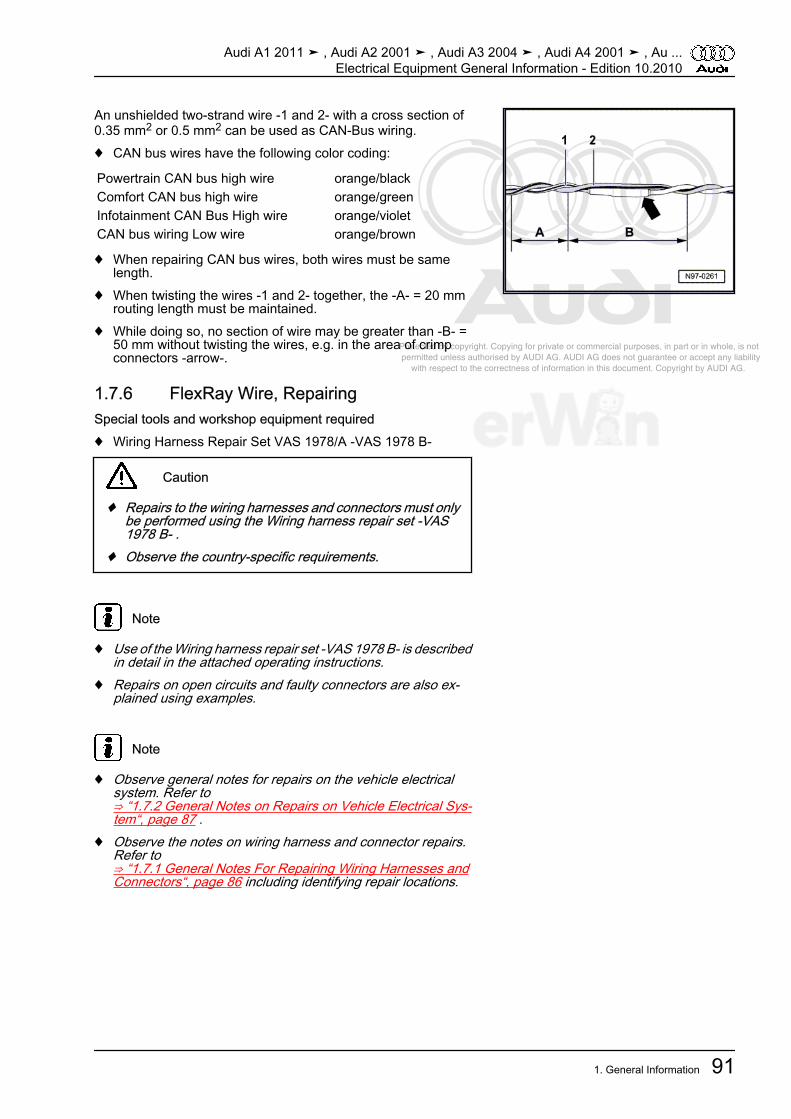
Protected by copyright. Copying for private or commercial purposes, in part or in whole, is not permitted unless authorised by AUDI AG. AUDI AG does not guarantee or accept any liability with respect to the correctness of information in this document. Copyright by AUDI AG.
An unshielded two-strand wire -1 and 2- with a cross section of0.35 mm2 or 0.5 mm2 can be used as CAN-Bus wiring.♦ CAN bus wires have the following color coding:
Powertrain CAN bus high wire orange/blackComfort CAN bus high wire orange/greenInfotainment CAN Bus High wire orange/violetCAN bus wiring Low wire orange/brown
♦ When repairing CAN bus wires, both wires must be samelength.
♦ When twisting the wires -1 and 2- together, the -A- = 20 mmrouting length must be maintained.
♦ While doing so, no section of wire may be greater than -B- =50 mm without twisting the wires, e.g. in the area of crimpconnectors -arrow-.
1.7.6 FlexRay Wire, RepairingSpecial tools and workshop equipment required♦ Wiring Harness Repair Set VAS 1978/A -VAS 1978 B-
Caution
♦ Repairs to the wiring harnesses and connectors must onlybe performed using the Wiring harness repair set -VAS1978 B- .
♦ Observe the country-specific requirements.
Note
♦ Use of the Wiring harness repair set -VAS 1978 B- is describedin detail in the attached operating instructions.
♦ Repairs on open circuits and faulty connectors are also ex‐plained using examples.
Note
♦ Observe general notes for repairs on the vehicle electricalsystem. Refer to⇒ “1.7.2 General Notes on Repairs on Vehicle Electrical Sys‐tem“, page 87 .
♦ Observe the notes on wiring harness and connector repairs.Refer to⇒ “1.7.1 General Notes For Repairing Wiring Harnesses andConnectors“, page 86 including identifying repair locations.
Audi A1 2011 ➤ , Audi A2 2001 ➤ , Audi A3 2004 ➤ , Audi A4 2001 ➤ , Au ...Electrical Equipment General Information - Edition 10.2010
1. General Information 91
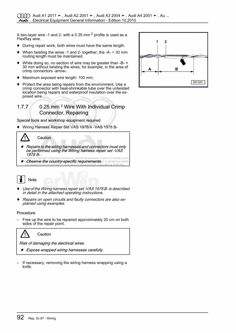
Protected by copyright. Copying for private or commercial purposes, in part or in whole, is not permitted unless authorised by AUDI AG. AUDI AG does not guarantee or accept any liability with respect to the correctness of information in this document. Copyright by AUDI AG.
A two-layer wire -1 and 2- with a 0.35 mm 2 profile is used as aFlexRay wire.♦ During repair work, both wires must have the same length.♦ When twisting the wires -1 and 2- together, the -A- = 30 mm
routing length must be maintained.♦ While doing so, no section of wire may be greater than -B- =
30 mm without twisting the wires, for example, in the area ofcrimp connectors -arrow-.
♦ Maximum exposed wire length: 100 mm.♦ Protect the area being repairs from the environment. Use a
crimp connector with heat-shrinkable tube over the untwistedlocation being repairs and waterproof insulation over the ex‐posed wire.
1.7.7 0.25 mm 2 Wire With Individual CrimpConnector, Repairing
Special tools and workshop equipment required♦ Wiring Harness Repair Set VAS 1978/A -VAS 1978 B-
Caution
♦ Repairs to the wiring harnesses and connectors must onlybe performed using the Wiring harness repair set -VAS1978 B- .
♦ Observe the country-specific requirements.
Note
♦ Use of the Wiring harness repair set -VAS 1978 B- is describedin detail in the attached operating instructions.
♦ Repairs on open circuits and faulty connectors are also ex‐plained using examples.
Procedure– Free up the wire to be repaired approximately 20 cm on both
sides of the repair point.
Caution
Risk of damaging the electrical wires.♦ Expose wrapped wiring harnesses carefully.
– If necessary, removing the wiring harness wrapping using aknife.
Audi A1 2011 ➤ , Audi A2 2001 ➤ , Audi A3 2004 ➤ , Audi A4 2001 ➤ , Au ...Electrical Equipment General Information - Edition 10.2010
92 Rep. Gr.97 - Wiring
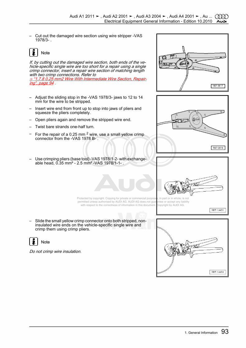
Protected by copyright. Copying for private or commercial purposes, in part or in whole, is not permitted unless authorised by AUDI AG. AUDI AG does not guarantee or accept any liability with respect to the correctness of information in this document. Copyright by AUDI AG.
– Cut out the damaged wire section using wire stripper -VAS1978/3- .
Note
If, by cutting out the damaged wire section, both ends of the ve‐hicle-specific single wire are too short for a repair using a singlecrimp connector, insert a repair wire section of matching lengthwith two crimp connections. Refer to⇒ “1.7.8 0.25 mm2 Wire With Intermediate Wire Section, Repair‐ing“, page 94 .
– Adjust the sliding stop in the -VAS 1978/3- jaws to 12 to 14mm for the wire to be stripped.
– Insert wire end from front up to stop into jaws of pliers andsqueeze the pliers completely.
– Open pliers again and remove the stripped wire end.– Twist bare strands one-half turn.– For the repair of a 0.25 mm 2 wire, use a small yellow crimp
connector from the -VAS 1978 B- .
– Use crimping pliers (base tool) -VAS 1978/1-2- with exchange‐able head, 0.35 mm² - 2.5 mm² -VAS 1978/1-1- .
– Slide the small yellow crimp connector onto both stripped, non-insulated wire ends on the vehicle-specific single wire andcrimp them using crimp pliers.
Note
Do not crimp wire insulation.
Audi A1 2011 ➤ , Audi A2 2001 ➤ , Audi A3 2004 ➤ , Audi A4 2001 ➤ , Au ...Electrical Equipment General Information - Edition 10.2010
1. General Information 93
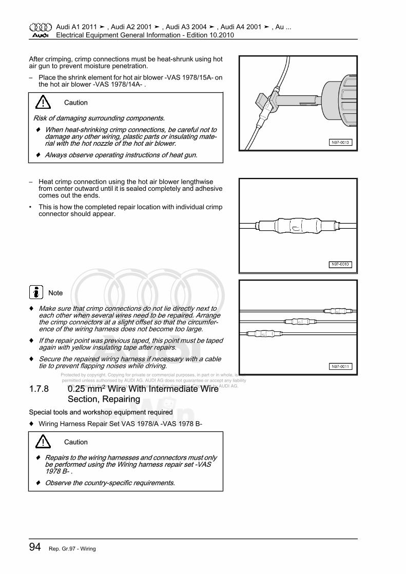
Protected by copyright. Copying for private or commercial purposes, in part or in whole, is not permitted unless authorised by AUDI AG. AUDI AG does not guarantee or accept any liability with respect to the correctness of information in this document. Copyright by AUDI AG.
After crimping, crimp connections must be heat-shrunk using hotair gun to prevent moisture penetration.– Place the shrink element for hot air blower -VAS 1978/15A- on
the hot air blower -VAS 1978/14A- .
Caution
Risk of damaging surrounding components.♦ When heat-shrinking crimp connections, be careful not to
damage any other wiring, plastic parts or insulating mate‐rial with the hot nozzle of the hot air blower.
♦ Always observe operating instructions of heat gun.
– Heat crimp connection using the hot air blower lengthwisefrom center outward until it is sealed completely and adhesivecomes out the ends.
• This is how the completed repair location with individual crimpconnector should appear.
Note
♦ Make sure that crimp connections do not lie directly next toeach other when several wires need to be repaired. Arrangethe crimp connectors at a slight offset so that the circumfer‐ence of the wiring harness does not become too large.
♦ If the repair point was previous taped, this point must be tapedagain with yellow insulating tape after repairs.
♦ Secure the repaired wiring harness if necessary with a cabletie to prevent flapping noises while driving.
1.7.8 0.25 mm2 Wire With Intermediate WireSection, Repairing
Special tools and workshop equipment required♦ Wiring Harness Repair Set VAS 1978/A -VAS 1978 B-
Caution
♦ Repairs to the wiring harnesses and connectors must onlybe performed using the Wiring harness repair set -VAS1978 B- .
♦ Observe the country-specific requirements.
Audi A1 2011 ➤ , Audi A2 2001 ➤ , Audi A3 2004 ➤ , Audi A4 2001 ➤ , Au ...Electrical Equipment General Information - Edition 10.2010
94 Rep. Gr.97 - Wiring

Protected by copyright. Copying for private or commercial purposes, in part or in whole, is not permitted unless authorised by AUDI AG. AUDI AG does not guarantee or accept any liability with respect to the correctness of information in this document. Copyright by AUDI AG.
Note
♦ Use of the Wiring harness repair set -VAS 1978 B- is describedin detail in the attached operating instructions.
♦ Repairs on open circuits and faulty connectors are also ex‐plained using examples.
Note
Only 0.5 mm2 repair wires are available for repairing a 0.25mm2 wire.
Procedure– Free up the wire to be repaired at two places approximately
20 cm on both sides of the repair point.
Caution
Risk of damaging the electrical wires.♦ Expose wrapped wiring harnesses carefully.
– If necessary, removing the wiring harness wrapping using aknife.
– Route yellow repair wire next to damaged wiring harness andcut repair wire to the required length using wire stripper -VAS1978/3- .
– Cut damaged wire section from the vehicle-specific singlewire.
– Adjust the sliding stop in the -VAS 1978/3- jaws to 12 to 14mm for the wire to be stripped.
– Insert the vehicle-specific single wire end from the front intothe pliers jaws as far as the stop and squeeze the pliers to‐gether completely.
– Open pliers again and remove the stripped wire end.– Twist bare strands one-half turn.– Repeat the procedure on the other end of the vehicle-specific
individual wire.
Audi A1 2011 ➤ , Audi A2 2001 ➤ , Audi A3 2004 ➤ , Audi A4 2001 ➤ , Au ...Electrical Equipment General Information - Edition 10.2010
1. General Information 95
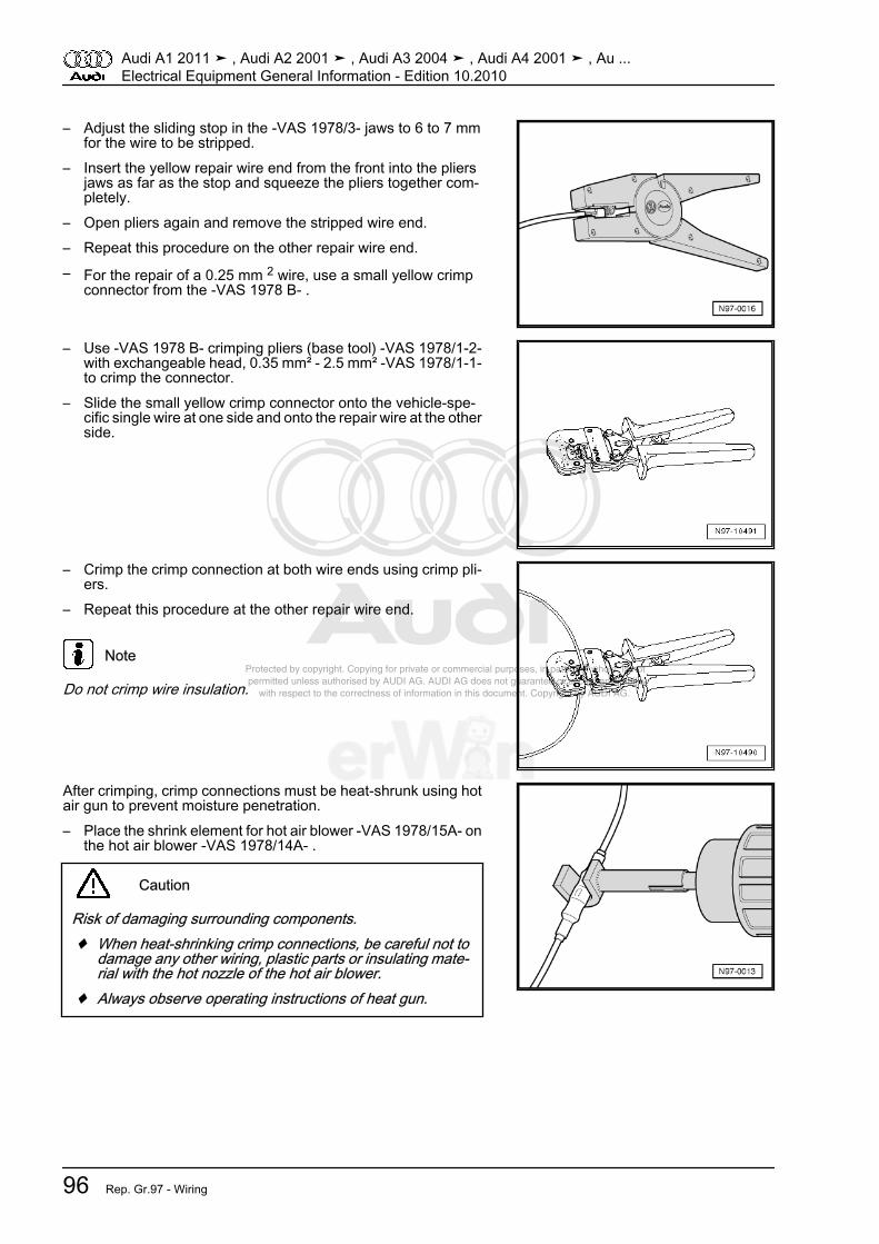
Protected by copyright. Copying for private or commercial purposes, in part or in whole, is not permitted unless authorised by AUDI AG. AUDI AG does not guarantee or accept any liability with respect to the correctness of information in this document. Copyright by AUDI AG.
– Adjust the sliding stop in the -VAS 1978/3- jaws to 6 to 7 mmfor the wire to be stripped.
– Insert the yellow repair wire end from the front into the pliersjaws as far as the stop and squeeze the pliers together com‐pletely.
– Open pliers again and remove the stripped wire end.– Repeat this procedure on the other repair wire end.– For the repair of a 0.25 mm 2 wire, use a small yellow crimp
connector from the -VAS 1978 B- .
– Use -VAS 1978 B- crimping pliers (base tool) -VAS 1978/1-2-with exchangeable head, 0.35 mm² - 2.5 mm² -VAS 1978/1-1-to crimp the connector.
– Slide the small yellow crimp connector onto the vehicle-spe‐cific single wire at one side and onto the repair wire at the otherside.
– Crimp the crimp connection at both wire ends using crimp pli‐ers.
– Repeat this procedure at the other repair wire end.
Note
Do not crimp wire insulation.
After crimping, crimp connections must be heat-shrunk using hotair gun to prevent moisture penetration.– Place the shrink element for hot air blower -VAS 1978/15A- on
the hot air blower -VAS 1978/14A- .
Caution
Risk of damaging surrounding components.♦ When heat-shrinking crimp connections, be careful not to
damage any other wiring, plastic parts or insulating mate‐rial with the hot nozzle of the hot air blower.
♦ Always observe operating instructions of heat gun.
Audi A1 2011 ➤ , Audi A2 2001 ➤ , Audi A3 2004 ➤ , Audi A4 2001 ➤ , Au ...Electrical Equipment General Information - Edition 10.2010
96 Rep. Gr.97 - Wiring
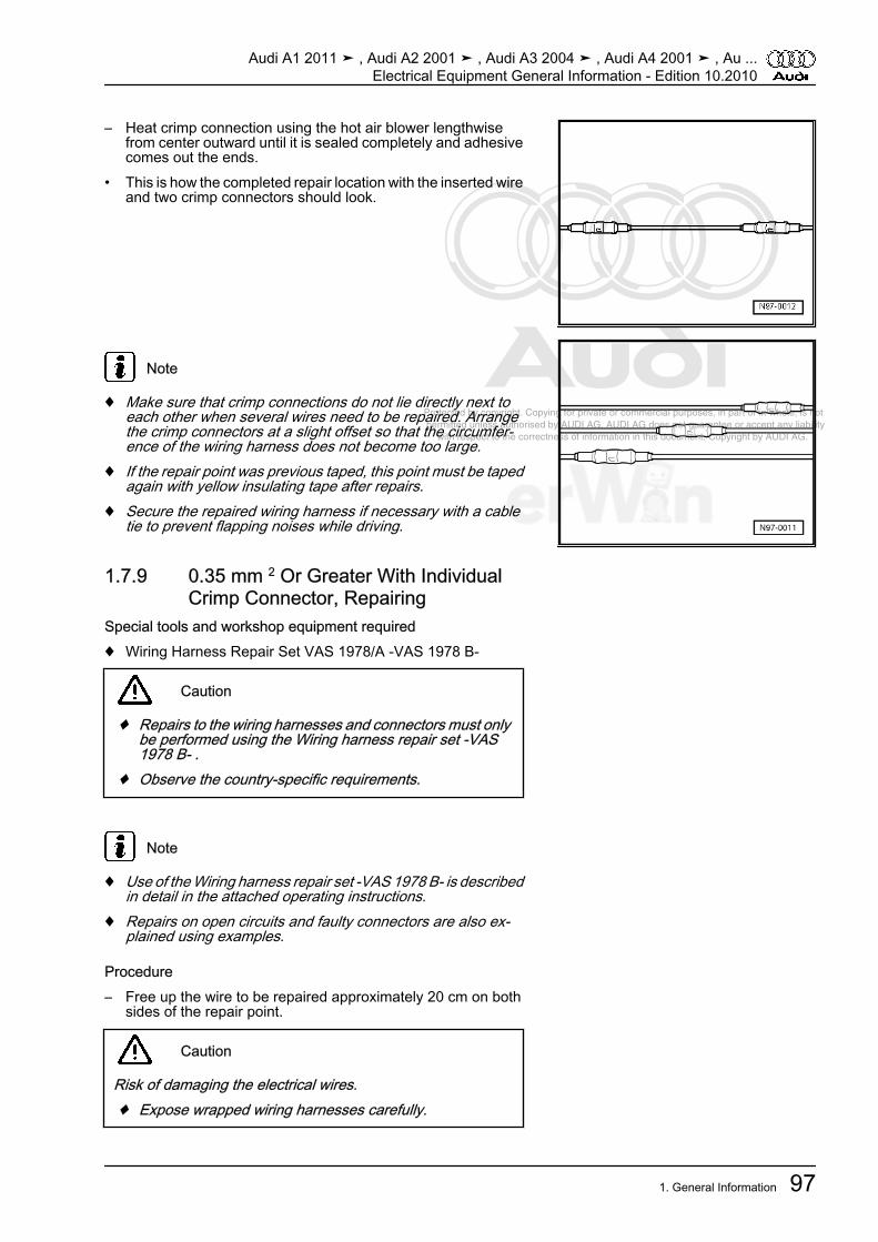
Protected by copyright. Copying for private or commercial purposes, in part or in whole, is not permitted unless authorised by AUDI AG. AUDI AG does not guarantee or accept any liability with respect to the correctness of information in this document. Copyright by AUDI AG.
– Heat crimp connection using the hot air blower lengthwisefrom center outward until it is sealed completely and adhesivecomes out the ends.
• This is how the completed repair location with the inserted wireand two crimp connectors should look.
Note
♦ Make sure that crimp connections do not lie directly next toeach other when several wires need to be repaired. Arrangethe crimp connectors at a slight offset so that the circumfer‐ence of the wiring harness does not become too large.
♦ If the repair point was previous taped, this point must be tapedagain with yellow insulating tape after repairs.
♦ Secure the repaired wiring harness if necessary with a cabletie to prevent flapping noises while driving.
1.7.9 0.35 mm 2 Or Greater With IndividualCrimp Connector, Repairing
Special tools and workshop equipment required♦ Wiring Harness Repair Set VAS 1978/A -VAS 1978 B-
Caution
♦ Repairs to the wiring harnesses and connectors must onlybe performed using the Wiring harness repair set -VAS1978 B- .
♦ Observe the country-specific requirements.
Note
♦ Use of the Wiring harness repair set -VAS 1978 B- is describedin detail in the attached operating instructions.
♦ Repairs on open circuits and faulty connectors are also ex‐plained using examples.
Procedure– Free up the wire to be repaired approximately 20 cm on both
sides of the repair point.
Caution
Risk of damaging the electrical wires.♦ Expose wrapped wiring harnesses carefully.
Audi A1 2011 ➤ , Audi A2 2001 ➤ , Audi A3 2004 ➤ , Audi A4 2001 ➤ , Au ...Electrical Equipment General Information - Edition 10.2010
1. General Information 97
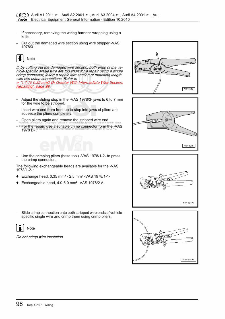
Protected by copyright. Copying for private or commercial purposes, in part or in whole, is not permitted unless authorised by AUDI AG. AUDI AG does not guarantee or accept any liability with respect to the correctness of information in this document. Copyright by AUDI AG.
– If necessary, removing the wiring harness wrapping using aknife.
– Cut out the damaged wire section using wire stripper -VAS1978/3- .
Note
If, by cutting out the damaged wire section, both ends of the ve‐hicle-specific single wire are too short for a repair using a singlecrimp connector, insert a repair wire section of matching lengthwith two crimp connections. Refer to⇒ “1.7.10 0.35 mm2 Or Greater With Intermediate Wire Section,Repairing“, page 99 .
– Adjust the sliding stop in the -VAS 1978/3- jaws to 6 to 7 mmfor the wire to be stripped.
– Insert wire end from front up to stop into jaws of pliers andsqueeze the pliers completely.
– Open pliers again and remove the stripped wire end.– For the repair, use a suitable crimp connector form the -VAS
1978 B- .
– Use the crimping pliers (base tool) -VAS 1978/1-2- to pressthe crimp connector.
The following exchangeable heads are available for the -VAS1978/1-2- :♦ Exchange head, 0,35 mm² - 2,5 mm² -VAS 1978/1-1-♦ Exchangeable head, 4.0-6.0 mm² -VAS 1978/2 A-
– Slide crimp connection onto both stripped wire ends of vehicle-specific single wire and crimp them using crimp pliers.
Note
Do not crimp wire insulation.
Audi A1 2011 ➤ , Audi A2 2001 ➤ , Audi A3 2004 ➤ , Audi A4 2001 ➤ , Au ...Electrical Equipment General Information - Edition 10.2010
98 Rep. Gr.97 - Wiring
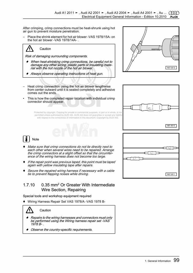
Protected by copyright. Copying for private or commercial purposes, in part or in whole, is not permitted unless authorised by AUDI AG. AUDI AG does not guarantee or accept any liability with respect to the correctness of information in this document. Copyright by AUDI AG.
After crimping, crimp connections must be heat-shrunk using hotair gun to prevent moisture penetration.– Place the shrink element for hot air blower -VAS 1978/15A- on
the hot air blower -VAS 1978/14A- .
Caution
Risk of damaging surrounding components.♦ When heat-shrinking crimp connections, be careful not to
damage any other wiring, plastic parts or insulating mate‐rial with the hot nozzle of the hot air blower.
♦ Always observe operating instructions of heat gun.
– Heat crimp connection using the hot air blower lengthwisefrom center outward until it is sealed completely and adhesivecomes out the ends.
• This is how the completed repair location with individual crimpconnector should appear.
Note
♦ Make sure that crimp connections do not lie directly next toeach other when several wires need to be repaired. Arrangethe crimp connectors at a slight offset so that the circumfer‐ence of the wiring harness does not become too large.
♦ If the repair point was previous taped, this point must be tapedagain with yellow insulating tape after repairs.
♦ Secure the repaired wiring harness if necessary with a cabletie to prevent flapping noises while driving.
1.7.10 0.35 mm2 Or Greater With IntermediateWire Section, Repairing
Special tools and workshop equipment required♦ Wiring Harness Repair Set VAS 1978/A -VAS 1978 B-
Caution
♦ Repairs to the wiring harnesses and connectors must onlybe performed using the Wiring harness repair set -VAS1978 B- .
♦ Observe the country-specific requirements.
Audi A1 2011 ➤ , Audi A2 2001 ➤ , Audi A3 2004 ➤ , Audi A4 2001 ➤ , Au ...Electrical Equipment General Information - Edition 10.2010
1. General Information 99

Protected by copyright. Copying for private or commercial purposes, in part or in whole, is not permitted unless authorised by AUDI AG. AUDI AG does not guarantee or accept any liability with respect to the correctness of information in this document. Copyright by AUDI AG.
Note
♦ Use of the Wiring harness repair set -VAS 1978 B- is describedin detail in the attached operating instructions.
♦ Repairs on open circuits and faulty connectors are also ex‐plained using examples.
Note
Only 0.5 mm2 repair wires are available for repairing a 0.35mm2 wire.
Procedure– Free up the wire to be repaired at two places approximately
20 cm on both sides of the repair point.
Caution
Risk of damaging the electrical wires.♦ Expose wrapped wiring harnesses carefully.
– If necessary, removing the wiring harness wrapping using aknife.
– Route yellow repair wire next to damaged wiring harness andcut repair wire to the required length using wire stripper -VAS1978/3- .
– Cut damaged wire section from the vehicle-specific singlewire.
– Adjust the sliding stop in the -VAS 1978/3- jaws to 6 to 7 mmfor the wire to be stripped.
– Insert the vehicle-specific single wire end from the front intothe pliers jaws as far as the stop and squeeze the pliers to‐gether completely.
– Open pliers again and remove the stripped wire end.– Repeat the procedure on the other end of the vehicle-specific
individual wire.– For the repair, use two suitable crimp connectors form the -
VAS 1978 B- .
Audi A1 2011 ➤ , Audi A2 2001 ➤ , Audi A3 2004 ➤ , Audi A4 2001 ➤ , Au ...Electrical Equipment General Information - Edition 10.2010
100 Rep. Gr.97 - Wiring

Protected by copyright. Copying for private or commercial purposes, in part or in whole, is not permitted unless authorised by AUDI AG. AUDI AG does not guarantee or accept any liability with respect to the correctness of information in this document. Copyright by AUDI AG.
– Use the crimping pliers (base tool) -VAS 1978/1-2- to pressthe crimp connector.
The following exchangeable heads are available for the -VAS1978/1-2- :♦ Exchange head, 0,35 mm² - 2,5 mm² -VAS 1978/1-1-♦ Exchangeable head, 4.0-6.0 mm² -VAS 1978/2 A-– Slide the crimp connector onto the vehicle-specific single wire
at one side and onto repair wire at the other side.
– Crimp the crimp connection at both wire ends using crimp pli‐ers.
– Repeat this procedure on the other wire ends.
Note
Do not crimp wire insulation.
After crimping, crimp connections must be heat-shrunk using hotair gun to prevent moisture penetration.– Place the shrink element for hot air blower -VAS 1978/15A- on
the hot air blower -VAS 1978/14A- .
Caution
Risk of damaging surrounding components.♦ When heat-shrinking crimp connections, be careful not to
damage any other wiring, plastic parts or insulating mate‐rial with the hot nozzle of the hot air blower.
♦ Always observe operating instructions of heat gun.
– Heat crimp connection using the hot air blower lengthwisefrom center outward until it is sealed completely and adhesivecomes out the ends.
• This is how the completed repair location with the inserted wireand two crimp connectors should look.
Audi A1 2011 ➤ , Audi A2 2001 ➤ , Audi A3 2004 ➤ , Audi A4 2001 ➤ , Au ...Electrical Equipment General Information - Edition 10.2010
1. General Information 101

Protected by copyright. Copying for private or commercial purposes, in part or in whole, is not permitted unless authorised by AUDI AG. AUDI AG does not guarantee or accept any liability with respect to the correctness of information in this document. Copyright by AUDI AG.
Note
♦ Make sure that crimp connections do not lie directly next toeach other when several wires need to be repaired. Arrangethe crimp connectors at a slight offset so that the circumfer‐ence of the wiring harness does not become too large.
♦ If the repair point was previous taped, this point must be tapedagain with yellow insulating tape after repairs.
♦ Secure the repaired wiring harness if necessary with a cabletie to prevent flapping noises while driving.
Audi A1 2011 ➤ , Audi A2 2001 ➤ , Audi A3 2004 ➤ , Audi A4 2001 ➤ , Au ...Electrical Equipment General Information - Edition 10.2010
102 Rep. Gr.97 - Wiring
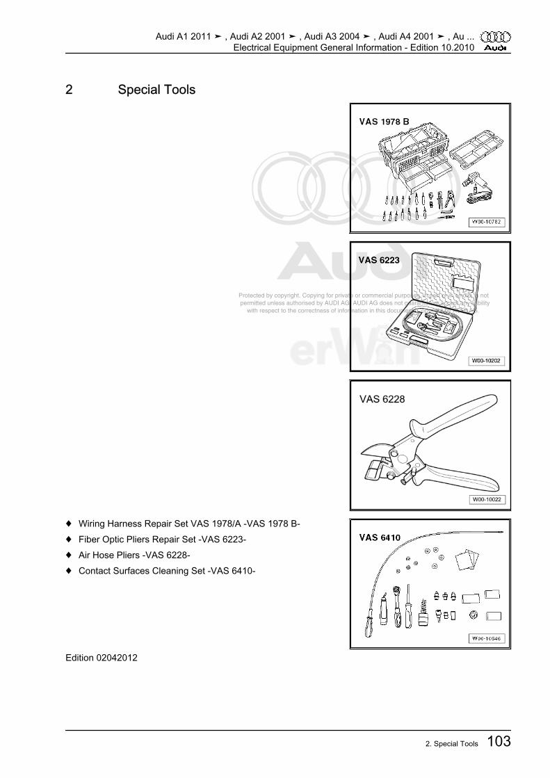
Protected by copyright. Copying for private or commercial purposes, in part or in whole, is not permitted unless authorised by AUDI AG. AUDI AG does not guarantee or accept any liability with respect to the correctness of information in this document. Copyright by AUDI AG.
2 Special Tools
♦ Wiring Harness Repair Set VAS 1978/A -VAS 1978 B-♦ Fiber Optic Pliers Repair Set -VAS 6223-♦ Air Hose Pliers -VAS 6228-♦ Contact Surfaces Cleaning Set -VAS 6410-
Edition 02042012
Audi A1 2011 ➤ , Audi A2 2001 ➤ , Audi A3 2004 ➤ , Audi A4 2001 ➤ , Au ...Electrical Equipment General Information - Edition 10.2010
2. Special Tools 103

Protected by copyright. Copying for private or commercial purposes, in part or in whole, is not permitted unless authorised by AUDI AG. AUDI AG does not guarantee or accept any liability with respect to the correctness of information in this document. Copyright by AUDI AG.
Cautions & Warnings
=Page 1 of 3 © 2002 Audi of America, Inc. All rights reserved. Information contained in this document is based on the latest information available at the time of printing and is subject to the copyright and other intellectual property rights of Audi of America, Inc., its affiliated companies and its licensors. All rights are reserved to make changes at any time without notice. No part of this document may be reproduced, stored in a retrieval system, or transmitted in any form or by any means, electronic, mechanical, photocopying, recording, or otherwise, nor may these materials be modified or reposted to other sites, without the prior expressed written permission of the publisher. Version 1.0
Please read these WARNINGS and CAUTIONS before proceeding with maintenance and repair work. You must answer that you have read and you understand these WARNINGS and CAUTIONS before you will be allowed to view this information.
•= If you lack the skills, tools and equipment, or a suitable workshop for any procedure described in this manual, we suggest you leave such repairs to an authorized Audi retailer or other qualified shop. We especially urge you to consult an authorized Audi retailer before beginning repairs on any vehicle that may still be covered wholly or in part by any of the extensive warranties issued by Audi.
•= Disconnect the battery negative terminal (ground strap)whenever you work on the fuel system or the electrical system. Do not smoke or work near heaters or other fire hazards. Keep an approved fire extinguisher handy.
•= Audi is constantly improving its vehicles and sometimes these changes, both in parts and specifications, are made applicable to earlier models. Therefore, part numbers listed in this manual are for reference only. Always check with your authorized Audi retailer parts department for the latest information.
•= Any time the battery has been disconnected on an automatic transmission vehicle, it will be necessary to reestablish Transmission Control Module (TCM) basic settings using the VAG 1551 Scan Tool (ST).
•= Never work under a lifted vehicle unless it is solidly supported on stands designed for the purpose. Do not support a vehicle on cinder blocks, hollow tiles or other props that may crumble under continuous load. Never work under a vehicle that is supported solely by a jack. Never work under the vehicle while the engine is running.
•= For vehicles equipped with an anti-theft radio, be sure of the correct radio activation code before disconnecting the battery or removing the radio. If the wrong code is entered when the power is restored, the radio may lock up and become inoperable, even if the correct code is used in a later attempt.
•= If you are going to work under a vehicle on the ground, make sure that the ground is level. Block the wheels to keep the vehicle from rolling. Disconnect the battery negative terminal (ground strap) to prevent others from starting the vehicle while you are under it.
•= Do not attempt to work on your vehicle if you do not feel well. You increase the danger of injury to yourself and others if you are tired, upset or have taken medicine or any other substances that may impair you or keep you from being fully alert.
•= Never run the engine unless the work area is well ventilated. Carbon monoxide (CO) kills.
•= Always observe good workshop practices. Wear goggles when you operate machine tools or work with acid. Wear goggles, gloves and other protective clothing whenever the job requires working with harmful substances.
•= Tie long hair behind your head. Do not wear a necktie, a scarf, loose clothing, or a necklace when you work near machine tools or running engines. If your hair, clothing, or jewelry were to get caught in the machinery, severe injury could result.

Protected by copyright. Copying for private or commercial purposes, in part or in whole, is not permitted unless authorised by AUDI AG. AUDI AG does not guarantee or accept any liability with respect to the correctness of information in this document. Copyright by AUDI AG.
Cautions & Warnings
=Page 2 of 3 © 2002 Audi of America, Inc. All rights reserved. Information contained in this document is based on the latest information available at the time of printing and is subject to the copyright and other intellectual property rights of Audi of America, Inc., its affiliated companies and its licensors. All rights are reserved to make changes at any time without notice. No part of this document may be reproduced, stored in a retrieval system, or transmitted in any form or by any means, electronic, mechanical, photocopying, recording, or otherwise, nor may these materials be modified or reposted to other sites, without the prior expressed written permission of the publisher. Version 1.0
•= Do not re-use any fasteners that are worn or deformed in normal use. Some fasteners are designed to be used only once and are unreliable and may fail if used a second time. This includes, but is not limited to, nuts, bolts, washers, circlips and cotter pins. Always follow the recommendations in this manual - replace these fasteners with new parts where indicated, and any other time it is deemed necessary by inspection.
•= Illuminate the work area adequately but safely. Use a portable safety light for working inside or under the vehicle. Make sure the bulb is enclosed by a wire cage. The hot filament of an accidentally broken bulb can ignite spilled fuel or oil.
•= Friction materials such as brake pads and clutch discs may contain asbestos fibers. Do not create dust by grinding, sanding, or by cleaning with compressed air. Avoid breathing asbestos fibers and asbestos dust. Breathing asbestos can cause serious diseases such as asbestosis or cancer, and may result in death.
•= Finger rings should be removed so that they cannot cause electrical shorts, get caught in running machinery, or be crushed by heavy parts.
•= Before starting a job, make certain that you have all the necessary tools and parts on hand. Read all the instructions thoroughly, do not attempt shortcuts. Use tools that are appropriate to the work and use only replacement parts meeting Audi specifications. Makeshift tools, parts and procedures will not make good repairs.
•= Catch draining fuel, oil or brake fluid in suitable containers. Do not use empty food or beverage containers that might mislead someone into drinking from them. Store flammable fluids away from fire hazards. Wipe up spills at once, but do not store the oily rags, which can ignite and burn spontaneously.
•= Use pneumatic and electric tools only to loosen threaded parts and fasteners. Never use these tools to tighten fasteners, especially on light alloy parts. Always use a torque wrench to tighten fasteners to the tightening torque listed.
•= Keep sparks, lighted matches, and open flame away from the top of the battery. If escaping hydrogen gas is ignited, it will ignite gas trapped in the cells and cause the battery to explode.
•= Be mindful of the environment and ecology. Before you drain the crankcase, find out the proper way to dispose of the oil. Do not pour oil onto the ground, down a drain, or into a stream, pond, or lake. Consult local ordinances that govern the disposal of wastes.
•= The air-conditioning (A/C) system is filled with a chemical refrigerant that is hazardous. The A/C system should be serviced only by trained automotive service technicians using approved refrigerant recovery/recycling equipment, trained in related safety precautions, and familiar with regulations governing the discharging and disposal of automotive chemical refrigerants.
•= Before doing any electrical welding on vehicles equipped with anti-lock brakes (ABS), disconnect the battery negative terminal (ground strap) and the ABS control module connector.
•= Do not expose any part of the A/C system to high temperatures such as open flame. Excessive heat will increase system pressure and may cause the system to burst.

Protected by copyright. Copying for private or commercial purposes, in part or in whole, is not permitted unless authorised by AUDI AG. AUDI AG does not guarantee or accept any liability with respect to the correctness of information in this document. Copyright by AUDI AG.
Cautions & Warnings
=Page 3 of 3 © 2002 Audi of America, Inc. All rights reserved. Information contained in this document is based on the latest information available at the time of printing and is subject to the copyright and other intellectual property rights of Audi of America, Inc., its affiliated companies and its licensors. All rights are reserved to make changes at any time without notice. No part of this document may be reproduced, stored in a retrieval system, or transmitted in any form or by any means, electronic, mechanical, photocopying, recording, or otherwise, nor may these materials be modified or reposted to other sites, without the prior expressed written permission of the publisher. Version 1.0
•= When boost-charging the battery, first remove the fuses for the Engine Control Module (ECM), the Transmission Control Module (TCM), the ABS control module, and the trip computer. In cases where one or more of these components is not separately fused, disconnect the control module connector(s).
•= Some of the vehicles covered by this manual are equipped with a supplemental restraint system (SRS), that automatically deploys an airbag in the event of a frontal impact. The airbag is operated by an explosive device. Handled improperly or without adequate safeguards, it can be accidentally activated and cause serious personal injury. To guard against personal injury or airbag system failure, only trained Audi Service technicians should test, disassemble or service the airbag system.
•= Do not quick-charge the battery (for boost starting) for longer than one minute, and do not exceed 16.5 volts at the battery with the boosting cables attached. Wait at least one minute before boosting the battery a second time.
•= Never use a test light to conduct electrical tests of the airbag system. The system must only be tested by trained Audi Service technicians using the VAG 1551 Scan Tool (ST) or an approved equivalent. The airbag unit must never be electrically tested while it is not installed in the vehicle.
•= Some aerosol tire inflators are highly flammable. Be extremely cautious when repairing a tire that may have been inflated using an aerosol tire inflator. Keep sparks, open flame or other sources of ignition away from the tire repair area. Inflate and deflate the tire at least four times before breaking the bead from the rim. Completely remove the tire from the rim before attempting any repair.
•= When driving or riding in an airbag-equipped vehicle, never hold test equipment in your hands or lap while the vehicle is in motion. Objects between you and the airbag can increase the risk of injury in an accident.
I have read and I understand these Cautions and Warnings.