servomotori asincroni vettoriali serie ma ma series ... · ... macchine elettriche rotanti ......
TRANSCRIPT
Servomotori asincroni vettoriali serie MA
MA series asynchronous vectorial servomotors
Manuale d'uso e manutenzione Operation and maintenance manual
Versione italiana pag. 2÷31 English version pag. 32÷59

2 SERVOMOTORI ASINCRONI VETTORIALI SERIE MA | Manual MA I T
I T Manual MA | SOMMARIO 3
SOMMARIO
AVVERTENZE GENERALI 4
PERSONALE QUALIFICATO 4
SICUREZZA 4
NORMATIVE DI RIFERIMENTO 5
RICEZIONE – CONSERVAZIONE 6
VERIFICHE ELETTRICHE 6
ACCOPPIAMENTO/PIAZZAMENTO 7
MESSA IN SERVIZIO 9
FUNZIONAMENTO 10
MANUTENZIONE PERIODICA 11
RICAMBI 11
SOSTITUZIONE CUSCINETTI MA 100÷225 11
SOSTITUZIONE CUSCINETTI MA 280 12
TABELLA MANUTENZIONE CUSCINETTI 13
LAYOUT INGRASSAGGIO SCUDO LATO ACCOPPIAMENTO 14
LAYOUT INGRASSAGGIO SCUDO LATO ENCODER 15
CONTROLLI IN CASO DI MALFUNZIONAMENTO 15
ACCESSORI / COMPONENTI 16
PROTEZIONE TERMICA 16
KLIXON (N.C.) 16
SONDA PT100 TIPO R8/3-2F20: 16
SONDA KTY84/130: 17
SONDA PTC TIPO SNM130ES520: 17
TRASDUTTORE 18
ENCODER ELTRA EH 80 K 19
ENCODER HEIDENHAIN ERN 430 20
ENCODER STEGMANN-SICK VFS 60 A (PROGRAMMABILE) 21
ENCODER HENGSTLER S 21 22
RESOLVER 23
RELÈ ANEMOSTATICO 24
SCHEMA PER IL COLLEGAMENTO DEI MOTORI 'MA' 25
COLLEGAMENTI 26
CUSCINETTI 26
DISPOSITIVO MESSA A TERRA DELL’ALBERO 27
FORI SCARICO CONDENSA 27
FRENO 28
FRENO “NIA” 29
FRENO “K” 30
TENSIONE ALIMENTAZIONE FRENO 30

4 AVVERTENZE GENERALI | Manual MA I T
AVVERTENZE GENERALI
Il presente manuale si riferisce solamente ai prodotti standard riportati nel catalogo. La MAGNETIC non si riterrà responsabile di mal funzionamenti od incidenti dovuti alla mancata applicazione delle indicazioni contenute nel presente manuale. A seguito sono riportati i punti principali per il corretto utilizzo dei motori asincroni vettoriali, con rotore a gabbia, serie MA.
PERSONALE QUALIFICATO
Questo manuale è rivolto ad un PERSONALE QUALIFICATO il quale deve conoscere ed osservare le disposizioni antinfortunistiche nazionali e le normative vigenti in ambito delle installazioni in bassa tensione. Sono necessarie le seguenti qualifiche:
Trasporto solo a persone con nozioni di movimentazione.
Montaggio meccanico solo meccanici qualificati.
Collegamento elettrico solo elettricisti specializzati.
Setup del motore solo tecnici qualificati con nozioni approfondite in meccanica, elettrotecnica e tecnologia di azionamenti.
SICUREZZA
I motori possiedono parti sotto tensione e parti in movimento per cui è necessario seguire alcune regole per non incorrere in situazioni di pericolo. La movimentazione, la messa in servizio, l’utilizzo ed l’eventuale riparazione devono essere eseguite da PERSONALE QUALIFICATO e solamente dopo avere seguito le seguenti disposizioni:
Il personale qualificato deve conoscere le procedure per l’istallazione, la manutenzione e l’utilizzo del motore ed avere letto tutto il presente manuale d’uso e manutenzione.
Il personale qualificato deve conoscere tutti i dati tecnici, le specifiche, i collegamenti elettrici relativi al motore da montare.
Tutte le lavorazioni devono essere vietate ad operatori non qualificati.
Al fine di ridurre azioni che potrebbero penalizzare l’operatore e/o persone o cose vicine al motore, è necessario osservare le seguenti avvertenze:
Particolare cura durante il posizionamento della macchina per non incorrere in accidentali cadute. L’albero motore è libero di ruotare e quindi non lo si deve utilizzare per la movimentazione. Sollevare e/o spostare i motori utilizzando solamente i golfari montati sul motore o con ancoraggi
idonei. Non porre parti del corpo in prossimità delle parti in rotazione (es.: albero motore). Utilizzare adeguati dispositivi di protezione individuale durante le lavorazioni in prossimità
dell’estremità d’asse (presenza di spigoli taglienti nella sede linguetta).
I T Manual MA | Normative di riferimento 5
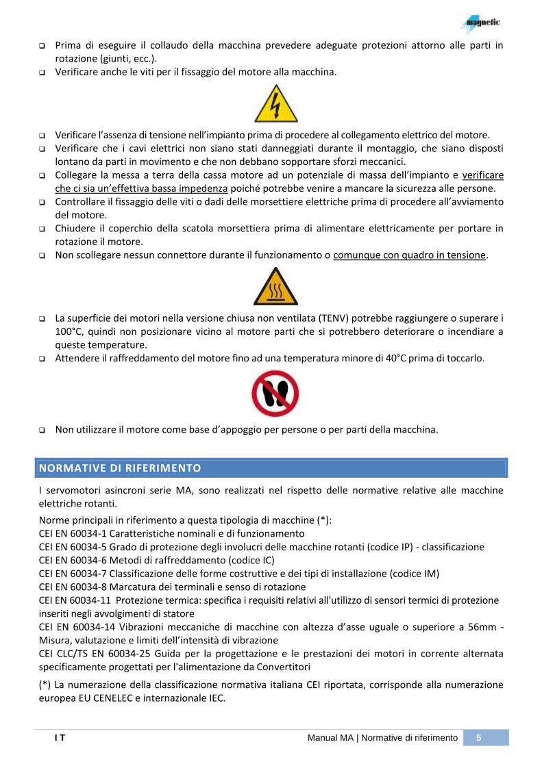
Prima di eseguire il collaudo della macchina prevedere adeguate protezioni attorno alle parti in rotazione (giunti, ecc.).
Verificare anche le viti per il fissaggio del motore alla macchina.
Verificare l’assenza di tensione nell’impianto prima di procedere al collegamento elettrico del motore. Verificare che i cavi elettrici non siano stati danneggiati durante il montaggio, che siano disposti
lontano da parti in movimento e che non debbano sopportare sforzi meccanici. Collegare la messa a terra della cassa motore ad un potenziale di massa dell’impianto e verificare
che ci sia un’effettiva bassa impedenza poiché potrebbe venire a mancare la sicurezza alle persone. Controllare il fissaggio delle viti o dadi delle morsettiere elettriche prima di procedere all’avviamento
del motore. Chiudere il coperchio della scatola morsettiera prima di alimentare elettricamente per portare in
rotazione il motore. Non scollegare nessun connettore durante il funzionamento o comunque con quadro in tensione.
La superficie dei motori nella versione chiusa non ventilata (TENV) potrebbe raggiungere o superare i 100°C, quindi non posizionare vicino al motore parti che si potrebbero deteriorare o incendiare a queste temperature.
Attendere il raffreddamento del motore fino ad una temperatura minore di 40°C prima di toccarlo.
Non utilizzare il motore come base d’appoggio per persone o per parti della macchina.
NORMATIVE DI RIFERIMENTO
I servomotori asincroni serie MA, sono realizzati nel rispetto delle normative relative alle macchine elettriche rotanti.
Norme principali in riferimento a questa tipologia di macchine (*): CEI EN 60034-1 Caratteristiche nominali e di funzionamento CEI EN 60034-5 Grado di protezione degli involucri delle macchine rotanti (codice IP) - classificazione CEI EN 60034-6 Metodi di raffreddamento (codice IC) CEI EN 60034-7 Classificazione delle forme costruttive e dei tipi di installazione (codice IM) CEI EN 60034-8 Marcatura dei terminali e senso di rotazione CEI EN 60034-11 Protezione termica: specifica i requisiti relativi all'utilizzo di sensori termici di protezione inseriti negli avvolgimenti di statore CEI EN 60034-14 Vibrazioni meccaniche di macchine con altezza d’asse uguale o superiore a 56mm - Misura, valutazione e limiti dell’intensità di vibrazione CEI CLC/TS EN 60034-25 Guida per la progettazione e le prestazioni dei motori in corrente alternata specificamente progettati per l'alimentazione da Convertitori
(*) La numerazione della classificazione normativa italiana CEI riportata, corrisponde alla numerazione europea EU CENELEC e internazionale IEC.
6 RICEZIONE – CONSERVAZIONE | Manual MA I T
I prodotti contenuti nel presente manuale sono realizzati nel rispetto della direttiva comunitaria “bassa tensione” (2006/95/CE)
I motori devono essere installati in conformità alle istruzioni fornite dal costruttore: la messa in servizio può essere effettuata solo dopo aver verificato che la macchina, dove verrà applicato il motore, sia conforme alle direttive di riferimento.
RICEZIONE – CONSERVAZIONE
Tutti i motori vengono accuratamente collaudati e controllati prima della spedizione. Ogni motore è fornito di un bollettino di collaudo dove sono inoltre riportate tutte le caratteristiche del motore e relativi accessori. All'arrivo è opportuno verificare che i motori non abbiano subito danni durante il trasporto; ogni eventuale inconveniente va subito segnalato. Se i motori non vengono subito installati vanno conservati in un ambiente asciutto e pulito privo di vibrazioni che potrebbero danneggiare i cuscinetti e protetto contro le brusche variazioni di temperatura generalmente causa di condensa. Verificare l'estremità d'asse e, se necessario, ripristinare lo strato di vernice protettiva con opportuni prodotti anticorrosivi. Se i motori prima dell'installazione sono stati per lungo tempo in ambiente a bassa temperatura, vanno lasciati per alcuni giorni a temperatura ambiente per eliminare l'eventuale condensa. In questo caso seguire le indicazioni riportate nel paragrafo seguente.
VERIFICHE ELETTRICHE
Prima della messa in servizio e dopo lunghi periodi di inattività o immagazzinamento è consigliabile eseguire i seguenti controlli :
- Verificare l'omogeneità delle 3 combinazioni di resistenza fase-fase e conformità al valore riportato sul bollettino di collaudo (le tre resistenze non devono divergere tra loro di circa +3%).
Si consiglia di eseguire la misura con un milliohmetro (NO multimetro, poiché la resistenza è troppo bassa e un comune tester non ha una sensibilità adeguata). Verificare inoltre, che il milliohmetro utilizzi una corrente di misura in dc (no pulsante o alternata).
- Il circuito di protezione termica deve avere resistenza prossima a zero (contatto NC). In questo caso e possibile utilizzare un normale multimetro. Impostare la scala in Ohm e misurare ai capi del protettore una resistenza ≤ 0.1Ω (Klixon con contatto normalmente chiuso). Se invece, il termoprottettore è una PT100, KTY84 o PTC, impostare sempre la scala Ohm e confrontare il valore di resistenza misurato con le tabelle riportate a paragrafo: “ACCESSORI /
COMPONENTI
Protezione termica”.
- Verificare che l'isolamento dell'avvolgimento verso massa e verso il termoprotettore sia superiore a 2
M mediante MEGGER con tensione di prova 500 o 1000 Vcc. Per questa misura è tassativo l’utilizzo del Megger munito con una adeguata tensione di prova. Eseguire la Misura tra una delle 3 fasi e la vite di massa, poi tra un filo del termoprottettore e la vite di massa ed infine tra una fase e un filo del termoprottettore. Dopo ogni misura, è necessario scaricare la tensione residua dovuta “all’effetto capacitivo” mediante con un cavetto tra i due capi dove è stata appena eseguita la misura.
Se non si riscontra il valore indicato significa che l'avvolgimento è umido e lo si dovrà essiccare ricorrendo ad una ditta specializzata.

I T Manual MA | Accoppiamento/piazzamento 7
ACCOPPIAMENTO/PIAZZAMENTO
Questa operazione è molto delicata e va eseguita con la massima cura per assicurare un buon funzionamento del motore. Nel caso di piazzamento del motore con piedi (IM1001-IMB3 o equivalente) è indispensabile che la superficie di fissaggio sia perfettamente in piano onde evitare deformazioni e/o rotture dello scudo: se necessario spessorare opportunamente sotto i piedi. L'organo di trasmissione va montato utilizzando il foro filettato in testa all'asse motore con apposito attrezzo. Nel montaggio sono assolutamente da evitare colpi che potrebbero danneggiare i cuscinetti. N.B. I rotori dei motori sono bilanciati con mezza linguetta quindi asse pieno e in grado A. Vanno quindi montati organi di trasmissione (ingranaggi, semigiunti, pulegge) bilanciati con mezza chiavetta (foro non strozzato). L'accoppiamento diretto con giunti deve essere eseguito in modo da ottenere un buon allineamento. In caso contrario possono manifestarsi forti vibrazioni, irregolarità di moto e spinte (forze) assiali sui cuscinetti compromettendo la loro vita . Visto l’importanza dell’allineamento raccomandiamo l’utilizzo di comparatori o strumenti al Laser per la verifica di tale allineamento. Se durante il funzionamento vengono riscontrati rumori o vibrazioni sul motore o sui cuscinetti, consigliamo di migliorare/ridurre il disallineamento mediante spessori appropriati. Nel caso di accoppiamento diretto in bagno d'olio assicurarsi che sia montato l'anello paraolio (con molla) che viene fornito solo su richiesta. A proposito consigliamo di verificare il valore del carico radiale usando la formula sotto riportata e confrontando questo con le tabelle riportate nella pagina successiva.
dove: Fr = carico radiale N P = potenza nominale del motore in kW n = velocità nominale del motore in RPM D = diametro della puleggia in mm
K = fattore di tensione fornito dal costruttore della puleggia e valutabile mediamente in :
k = 1.0 per cinghie dentellate k = 2.3 per cinghie trapezoidali k = 3.8 per cinghie piane
Qualora il valore della forza radiale, così calcolato, risulti maggiore di quello riportato sulle tabelle, si deve agire sui parametri che caratterizzano questo valore (aumentare il diametro della puleggia, modificare posizione del baricentro della forza, tipo e numero di cinghie..) o interpellare il ns. ufficio commerciale . Inoltre, è consigliabile misurare ogni 2000 ore di funzionamento la temperatura e le vibrazioni dei cuscinetti per evidenziare eventuali derive dei valori e risolvere . Riportiamo ora a seguito le tabelle con i carichi radiali massimi ammissibili per una durata teorica del cuscinetto lato accoppiamento di 20.000 ore.
Il tipo di cuscinetto è indicato nel paragrafo: “Cuscinetti”

8 ACCOPPIAMENTO/PIAZZAMENTO | Manual MA I T
MOTORE / MOTOR MA 100
X RPM
200 500 1000 1500 2000 2500 3000 4000 5000
[ mm ] Fr [ daN ]
0 557 407 315 269 241 220 205 182 166
40 479 350 275 239 215 199 186 167 152
60 448 327 257 223 201 186 174 157 145
80 379 307 241 209 189 175 163 148 136
MOTORE / MOTOR MA 133
X RPM
200 500 1000 1500 2000 2500 3000 4000 5000
[ mm ] Fr [ daN ]
0 1075 806 641 560 507 470 441 398 369
50 944 709 569 500 456 425 400 364 337
80 723 661 531 466 425 396 373 339 316
110 577 577 497 437 398 371 349 318 296
MOTORE / MOTOR MA 160
X RPM
200 500 1000 1500 2000 2500 3000 4000 5000
[ mm ] Fr [ daN ]
0 1667 1239 984 858 778 720 676 610 563
50 1108 1108 914 799 724 671 629 568 524
80 843 843 843 762 694 644 604 546 503
110 681 681 681 681 661 614 578 525 484
MOTORE / MOTOR MA 180
X RPM
200 500 1000 1500 2000 2500 3000 4000 5000
[ mm ] Fr [ daN ]
0 3168 2365 1888 1652 1501 1392 1309 1186 -
50 1584 1584 1584 1550 1410 1308 1229 1114 -
90 1099 1099 1099 1099 1099 1099 1099 1062 -
140 797 797 797 797 797 797 797 797 -
MOTORE / MOTOR MA 225
X RPM
200 500 1000 1500 2000 2500 3000 4000 5000
[ mm ] Fr [ daN ]
0 3054 2242 1760 1521 1368 1259 1174 - -
50 2881 2138 1678 1450 1304 1200 1119 - -
90 1653 1653 1618 1398 1258 1157 1079 - -
140 1079 1079 1079 1079 1079 1079 1033 - -
MOTORE / MOTOR MA 280
X RPM
200 500 1000 1500 2000 2500 3000 4000 5000
[ mm ] Fr [ daN ]
0 4853 3580 2823 2450 2210 2038 - - -
60 4587 3405 2686 2330 2102 1939 - - -
120 3272 3216 2560 2222 2005 1849 - - -
210 2076 2076 2076 2056 1865 1728 - - -

I T Manual MA | Messa in servizio 9
MESSA IN SERVIZIO
Prima dell'avviamento è necessario verificare quanto segue :
- controllare che la tensione di alimentazione dell'elettroventilatore coincida con quella riportata sulla targa (i valori sono riportati anche nella successiva tabella) e che il senso di rotazione della ventola sia concorde con quello della freccia presente nella carcassa del suddetto.
- Nel caso di ventilazione assistita a mezzo condotte, assicurarsi che le caratteristiche del ventilatore siano maggiori-uguali a quanto indicato in tabella:
Motore Versione Potenza di
targa kW@50Hz
Tensione [Vrms]
Corrente [Arms]
Rumoros. [dBA]
1
Tensione [Vrms]
Corrente [Arms]
Rumoros. [dBA]
1 Portata
[m³/h] Prevalenza [mmH2O]
Frequenza 50 Hz Frequenza 60 Hz
MA 100 IP54-PVAP 0.045 345÷440 200÷255
0.19 0.33
66 345÷460 200÷265
0.12 0.21
70 220 12
MA 133 IP54-PVAP 0.11 345÷480 200÷275
0.34 0.59
74 345÷480 200÷255
0.31 0.54
78 720 17
MA 133 IP23-PVA 0.37 315÷500 180÷290
1.1 1.82
75 380÷600 215÷350
1.1 1.82
79 930 93
MA 160 IP54-PVAP 0.166 380÷400 0.44 78 380÷440 0.5 80 1100 21
MA 160 IP23-PVA 1.1 300÷460 175÷265
2.6 4.5
78 360÷510 210÷290
2.6 4.5
82 1300 125
MA 180 IP54/IP23-PVA IP54-PVAP2
2.2 315÷400 180÷230
4.8 8.3
80 380÷480 220÷275
4.8 8.3
84 2200 120
MA 2252 IP54/IP23-PVA 3.0
380÷400 220÷230
6.0 10.4
86 460÷480 265÷275
6.0 10.4
86 3300 315
MA 2802 IP54/IP23-PVA 4.0
380÷400 220÷230
6.5 11.3
86 460÷480 265÷275
6.5 11.3
86 3900 285
1) riferito a 400V e alla media delle misure effettuate a 1 m. 2) Soltanto sulla taglia MA225 e MA280 sono previsti differenti ventilatori per 50Hz e 60Hz.
- Dopo lunghi periodi di inattività del motore controllare che non ci siano oggetti estranei all'interno del ventilatore i quali possono bloccare la rotazione della ventola.
- I motori vanno installati in modo da non ostacolare la circolazione dell'aria di raffreddamento in
entrata ed uscita, si consiglia una distanza minima ( 250 mm) tra i componenti della macchina ed il ventilatore.
- Verificare inoltre che l'aria in uscita (aria calda) non venga rimessa in circolo dal ventilatore penalizzando il raffreddamento del motore. ATTENZIONE : Lasciare l'elettroventilatore acceso almeno 30' dopo lo spegnimento del motore onde evitare il surriscaldamento del trasduttore e dei cuscinetti. - L'accoppiamento deve essere eseguito mediante piedini e flangia del motore, evitare assolutamente di fissare o appoggiare pesi sopra e/o lateralmente al pacco statorico.
- Verificare che le piastrine di chiusura foro fissaggio piedini scudo L.O. siano chiuse.
- Se il motore è in forma B5 ed installato orizzontalmente, è consigliabile l'utilizzo di un piolo o castelletto per l'appoggio dei piedini dello scudo L.O. evitando che il motore possa flettere (vedasi nota a catalogo).

10 FUNZIONAMENTO | Manual MA I T
- Durante la messa in servizio della macchina, verificare con oscilloscopio che non siano presenti elevati valori (e gradienti, dv/dt) di tensione ai terminali della scatola morsettiera a causa della veloce commutazione degli IGBT dell’inverter unita a situazioni di lunghi o particolari cablaggi: sono riscontrabili picchi di tensione molto elevati dell’ordine dei kV e potrebbe essere necessario adottare delle contromisure (per es. l’inserimento di induttanze o filtri) per attenuare il fenomeno.
La misura deve essere effettuata da personale specializzato con strumentazione adeguata. Nella figura a fianco è riportata una tipica visualizzazione del fenomeno.
FUNZIONAMENTO
Tutti i motori sono a 4 poli, ciò significa che la velocità (a vuoto) è legata alla frequenza dalla relazione semplificata :
30
nfo
Nel funzionamento a carico la frequenza di alimentazione deve essere aumentata, per mantenere costante la velocità, del valore di scorrimento 'fs' che dipende dal carico (coppia, T) del motore:
Tn
Tfsnfs
Questa relazione è valida nel funzionamento a coppia costante, mentre per l'utilizzo in regolazione a potenza costante diventa:
nn
n
Tn
Tfsnfs
Sommando il valore ‘fo’ e ‘fs’ si ottiene la frequenza di alimentazione del motore (vedasi la targa o il catalogo del motore per il valore alla velocità nominale ‘nn’). Es. MA 133 M-F1 con Fn=51.3Hz e n=1500RPM, si ricava fo=50Hz e quindi Fsn=1.3Hz. Si ricordi inoltre che lo scorrimento aumenta con la temperatura della macchina (fino ad un 37%): i valori riportati si riferiscono alla massima temperatura. Per quanto riguarda la tensione, il valore è legato alla frequenza (quindi alla velocità) e vale:
f
V
fn
Vn
nella regolazione a coppia costante. Questa formula è approssimativa poiché dovrebbe essere riferita a quella parte della tensione che genera il flusso da cui però differisce a causa delle cadute di tensione di qualche percento (l’errore diventa elevato a basse velocità). A velocità nominale il valore a pieno carico deve essere pari a ‘Vn’ per ottenere le caratteristiche di targa del motore. Nella regolazione a potenza costante all’aumento della frequenza si determinano cadute di tensione sempre maggiori che richiedono ai capi del motore una tensione disponibile più elevata. Ne consegue che il valore nmax1 è determinato dalla tensione massima disponibile dall’inverter: risulta tipico considerare una tensione sinusoidale al motore di 350÷360VRMS con tensione di linea di 380÷400VRMS. La differenza di tensione tra ingresso e uscita del convertitore è dovuta alla caduta ai capi degli IGBT, dal tipo di modulazione e ad un margine di tensione riservato per i sovraccarichi. Oltre che dalla tensione, le prestazioni del motore dipendono dall’inverter: ad esempio la risposta dinamica dipende dall’algoritmo di calcolo utilizzato (scalare V/f o vettoriale ad orientamento di campo), mentre il rumore e le perdite dalla frequenza di switching dell’inverter.
I T Manual MA | Manutenzione periodica 11
MANUTENZIONE PERIODICA
Per raggiungere buoni traguardi di vita delle macchine, occorre effettuare almeno alcuni accorgimenti/controlli:
- Se il motore è provvisto di ingrassatore attenersi agli intervalli indicati nella targa del motore avendo cura di far fuoriuscire il grasso esausto tramite i previsti passaggi.
- Dopo i primi 3 mesi di funzionamento: verificare che la rumorosità e le vibrazioni non siano incrementate segno di problematiche legate principalmente allo stato dei cuscinetti; verificare la funzionalità del ventilatore e lo stato del filtro (quando previsto, da sostituire se necessario).
- Ogni 12 mesi: disaccoppiare la macchina dall’impianto per verificare che il rotore sia libero di ruotare senza impuntamenti e senza rumori anomali; scollegare elettricamente la macchina per
verificare l’isolamento (paragrafo VERIFICHE ELETTRICHE); verificare la funzionalità del ventilatore, verifica vibrazioni per lo stato dei cuscinetti, ispezione interna IP23 / passaggi aria IP 54 perché non ci siano ostacoli per l’aria del ventilatore.
- Verificare periodicamente lo stato del filtro dell’elettroventilatore che, se sporco o intasato, deve essere soffiato o sostituito poiché la ridotta efficienza del raffreddamento può danneggiare il motore. L’intervallo di manutenzione di questo elemento non può essere definito a priori dato che dipende dalle condizioni ambientali di funzionamento.
Quanto sopra costituisce una base minima da adattare all’effettivo utilizzo della macchina e all’importanza della continuità del servizio per l’impianto su cui è installata.
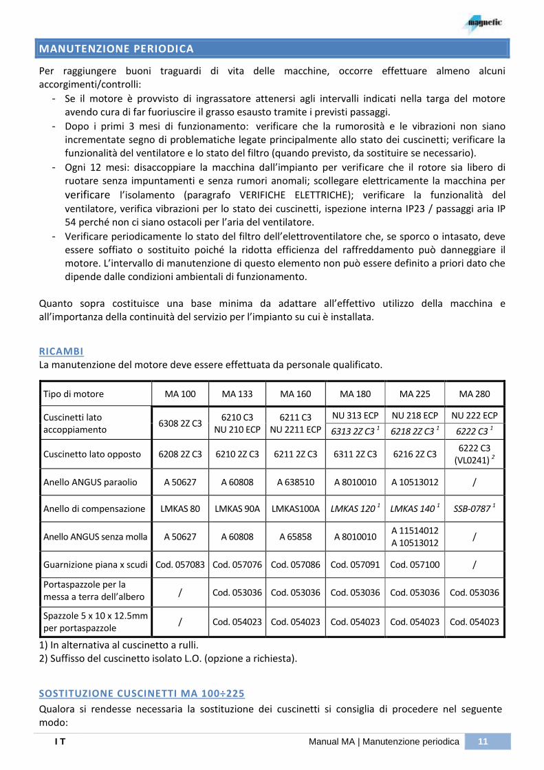
RICAMBI La manutenzione del motore deve essere effettuata da personale qualificato.
Tipo di motore MA 100 MA 133 MA 160 MA 180 MA 225 MA 280
Cuscinetti lato accoppiamento
6308 2Z C3 6210 C3
NU 210 ECP 6211 C3
NU 2211 ECP
NU 313 ECP NU 218 ECP NU 222 ECP
6313 2Z C3 1 6218 2Z C3 1 6222 C3 1
Cuscinetto lato opposto 6208 2Z C3 6210 2Z C3 6211 2Z C3 6311 2Z C3 6216 2Z C3 6222 C3
(VL0241) 2
Anello ANGUS paraolio A 50627 A 60808 A 638510 A 8010010 A 10513012 /
Anello di compensazione LMKAS 80 LMKAS 90A LMKAS100A LMKAS 120 1 LMKAS 140 1 SSB-0787 1
Anello ANGUS senza molla A 50627 A 60808 A 65858 A 8010010 A 11514012 A 10513012
/
Guarnizione piana x scudi Cod. 057083 Cod. 057076 Cod. 057086 Cod. 057091 Cod. 057100 /
Portaspazzole per la messa a terra dell’albero / Cod. 053036 Cod. 053036 Cod. 053036 Cod. 053036 Cod. 053036
Spazzole 5 x 10 x 12.5mm per portaspazzole
/ Cod. 054023 Cod. 054023 Cod. 054023 Cod. 054023 Cod. 054023
1) In alternativa al cuscinetto a rulli. 2) Suffisso del cuscinetto isolato L.O. (opzione a richiesta).
SOSTITUZIONE CUSCINETTI MA 100÷225
Qualora si rendesse necessaria la sostituzione dei cuscinetti si consiglia di procedere nel seguente modo:
12 MANUTENZIONE PERIODICA | Manual MA I T
a) togliere l'elettroventilatore, l'eventuale calotta e il trasduttore, per quest’ultimo seguire l’istruzione indicate nel paragrafo ”Trasduttore”;
b) per facilitare il rimontaggio, contrassegnare durante lo smontaggio la posizione di origine delle parti (es.: con matita colorata, puntina ecc.);
c) togliere le viti di fissaggio flangia bloccaggio cuscinetto poste davanti nello scudo L.A. e successivamente le viti di fissaggio scudi dalla cassa, togliere con cautela gli scudi;
d) togliere i cuscinetti con apposito estrattore ed effettuare un'accurata pulizia delle parti lavorate dell'albero ed eliminare il grasso esausto;
e) per i motori con un cuscinetto a sfere su L.A., scaldare il cuscinetto in un bagno d'olio a 80÷100 °C, montarlo sull'albero tenendolo appoggiato sullo spallamento dell'asse fino al raffreddamento verificando alla fine che esso non si muova sull'albero;
f) per i motori MA 133-160 (lato L.A.) che presentano due cuscinetti, inserire prima il cuscinetto a sfere come descritto nel punto [e] e poi quello a rulli;
g) per il cuscinetto a rulli procedere come indicato nel punto [e] montando l’anello interno sull'albero fino in battuta al cuscinetto a sfere o allo spallamento; una volta raffreddato, montare la parte esterna.
h) Ingrassare il cuscinetto con un 30% della quantità indicata in tabella (quantità iniziale).
i) Riassemblare il motore procedendo in modo opposto allo smontaggio;
j) Portando in rotazione il rotore completare l’ingrassaggio fino alla quantità prevista utilizzando l’apposito ingrassatore (è posto all’esterno in alto su MA225 IP54 e MA160 IP54; all’esterno sul fronte vicino all’albero su MA133 IP54; interno sotto lo sportello superiore su MA180 IP54/23 MA133-160 IP23).
SOSTITUZIONE CUSCINETTI MA 280
Qualora si rendesse necessaria la sostituzione dei cuscinetti si consiglia di procedere nel seguente modo:
a) togliere l'elettroventilatore, l'eventuale calotta e il trasduttore, per quest’ultimo seguire l’istruzione indicate nel paragrafo “Errore. L'origine riferimento non è stata trovata.”;
b) per facilitare il rimontaggio, contrassegnare durante lo smontaggio la posizione di origine delle parti (es.: con matita colorata, puntina ecc.);
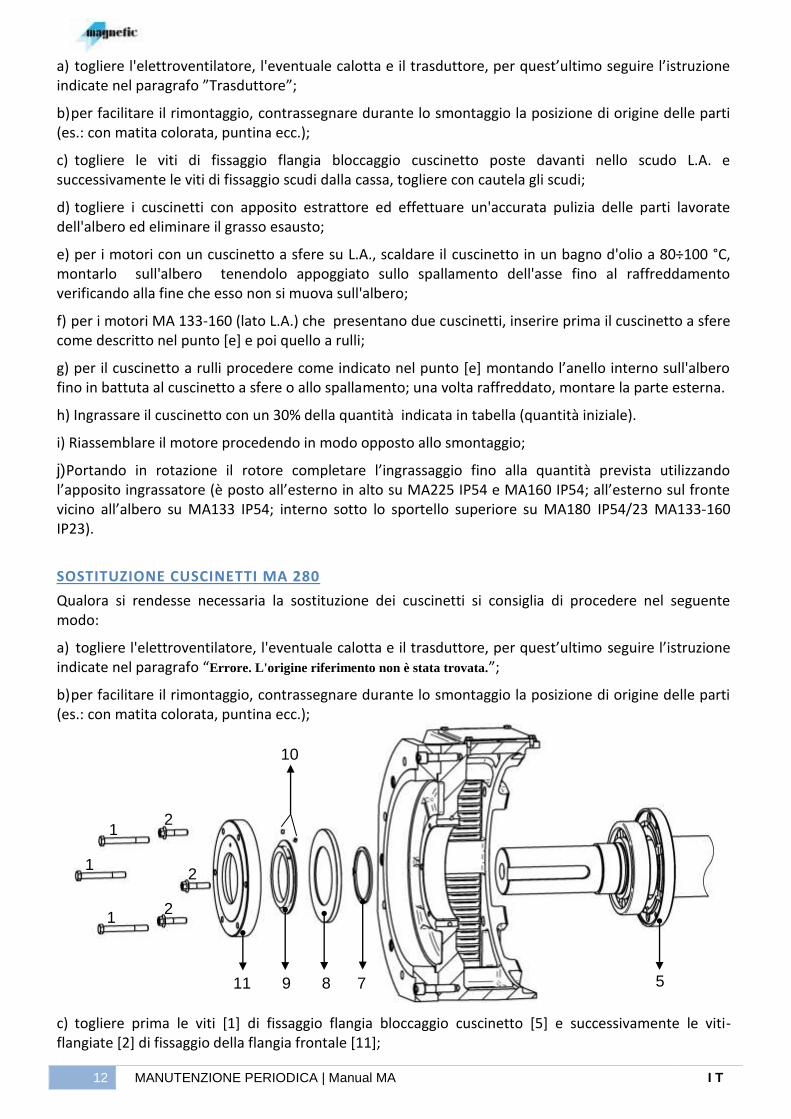
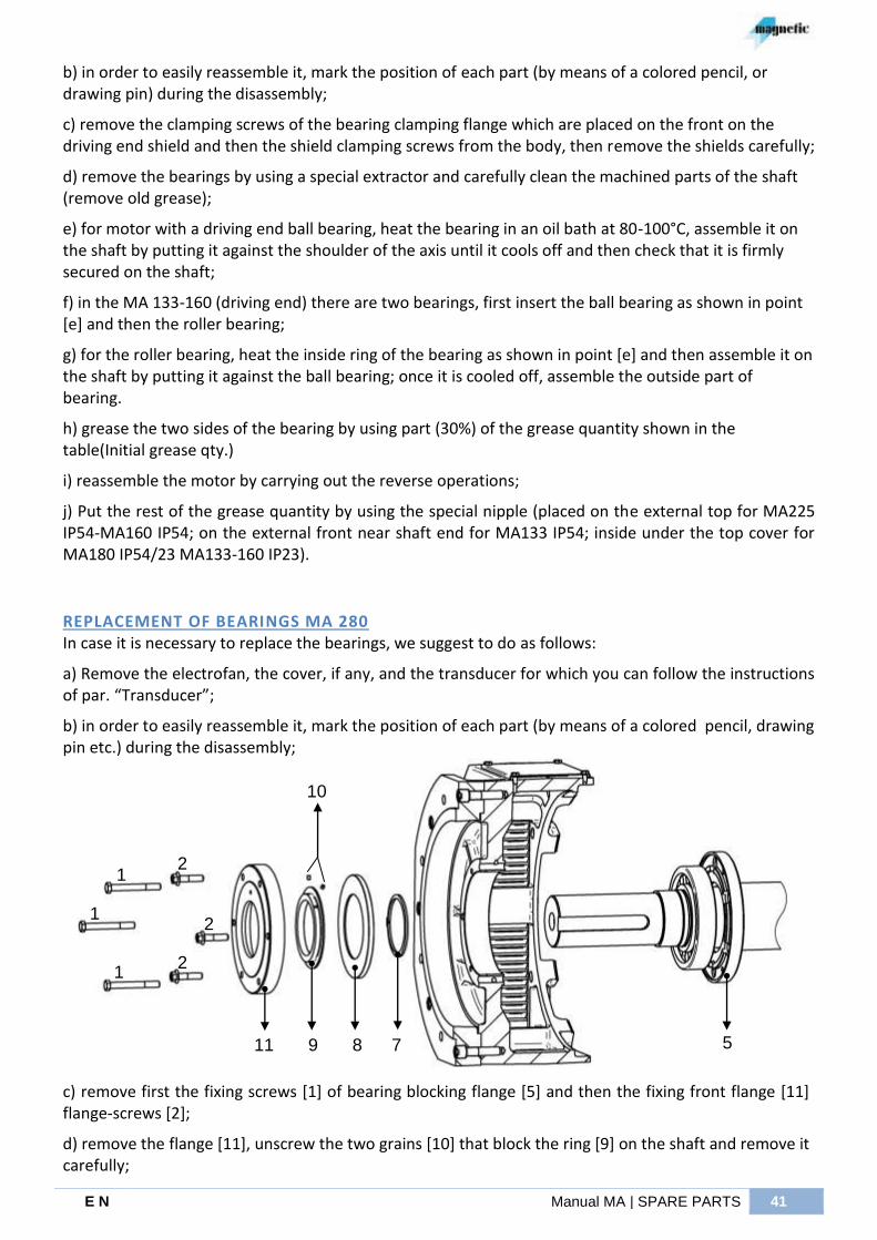
c) togliere prima le viti [1] di fissaggio flangia bloccaggio cuscinetto [5] e successivamente le viti-flangiate [2] di fissaggio della flangia frontale [11];
2
2
2 1
1
1
11 9 8 7 5
10
I T Manual MA | Manutenzione periodica 13
d) togliere la flangia [11], svitare i due grani [10] che bloccano anello [9] sull’albero ed estrarlo con cautela;
e) rimuovere il particolare [8] e, se presente, l’anello seeger [7]; f) togliere le viti di fissaggio scudi dalla cassa, rimuovere con cautela gli scudi;
g) togliere i cuscinetti con apposito estrattore ed effettuare un'accurata pulizia delle parti lavorate dell'albero ed eliminare il grasso esausto; h) per i cuscinetti a sfere scaldare il cuscinetto in un bagno d'olio a 80÷100 °C, montarlo sull'albero tenendolo appoggiato sullo spallamento dell'asse fino al raffreddamento verificando alla fine che esso non si muova sull'albero;
i) per il cuscinetto a rulli procedere come indicato nel punto [h] montando l’anello interno sull'albero tenendolo appoggiato sullo spal-lamento dell'asse fino al raffreddamento verificando alla fine che esso non si muova sull'albero.
j) Ingrassare il cuscinetto con un 30% della quantità indicata in tabella (quant. iniziale).
k) Riassemblare il motore procedendo in modo opposto allo smontaggio;
l) Portando in rotazione il rotore completare l’ingrassaggio fino alla quantità prevista utilizzando l’apposito ingrassatore (è posto in alto nella flangia [11] su L.A., e ai lati dello scudo L.O.).
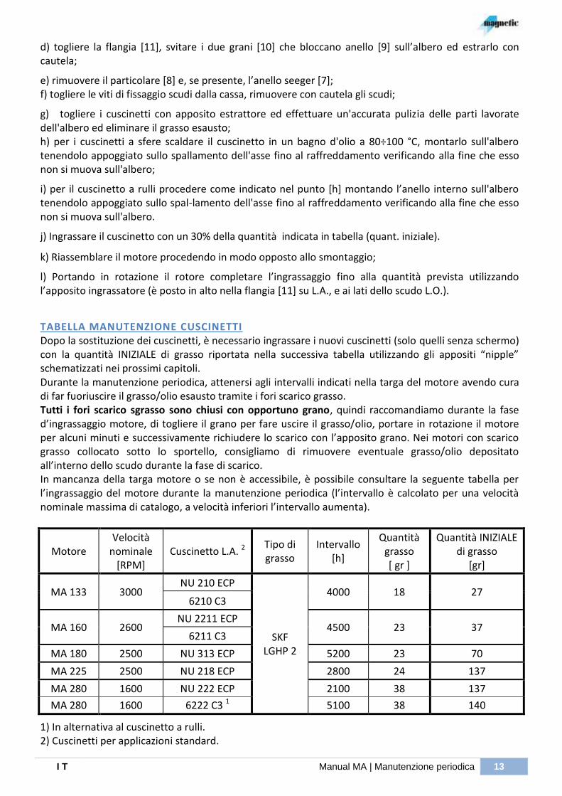
TABELLA MANUTENZIONE CUSCINETTI Dopo la sostituzione dei cuscinetti, è necessario ingrassare i nuovi cuscinetti (solo quelli senza schermo) con la quantità INIZIALE di grasso riportata nella successiva tabella utilizzando gli appositi “nipple” schematizzati nei prossimi capitoli. Durante la manutenzione periodica, attenersi agli intervalli indicati nella targa del motore avendo cura di far fuoriuscire il grasso/olio esausto tramite i fori scarico grasso. Tutti i fori scarico sgrasso sono chiusi con opportuno grano, quindi raccomandiamo durante la fase d’ingrassaggio motore, di togliere il grano per fare uscire il grasso/olio, portare in rotazione il motore per alcuni minuti e successivamente richiudere lo scarico con l’apposito grano. Nei motori con scarico grasso collocato sotto lo sportello, consigliamo di rimuovere eventuale grasso/olio depositato all’interno dello scudo durante la fase di scarico. In mancanza della targa motore o se non è accessibile, è possibile consultare la seguente tabella per l’ingrassaggio del motore durante la manutenzione periodica (l’intervallo è calcolato per una velocità nominale massima di catalogo, a velocità inferiori l’intervallo aumenta).
Motore Velocità
nominale [RPM]
Cuscinetto L.A. 2 Tipo di grasso
Intervallo [h]
Quantità grasso [ gr ]
Quantità INIZIALE di grasso
[gr]
MA 133 3000 NU 210 ECP
SKF LGHP 2
4000 18 27 6210 C3
MA 160 2600 NU 2211 ECP
4500 23 37 6211 C3
MA 180 2500 NU 313 ECP 5200 23 70
MA 225 2500 NU 218 ECP 2800 24 137
MA 280 1600 NU 222 ECP 2100 38 137
MA 280 1600 6222 C3 1 5100 38 140
1) In alternativa al cuscinetto a rulli. 2) Cuscinetti per applicazioni standard.

14 MANUTENZIONE PERIODICA | Manual MA I T
Motore Velocità
nominale [RPM]
Cuscinetto L.O. 2 Tipo di grasso
Intervallo [h]
Quantità grasso [ gr ]
Quantità INIZIALE di grasso
[gr]
MA 280 1600 6222 C3
(VL0241) optional SKF
LGHP 2 5100 38 120
N.B.: i valori riportati sono riferiti ad una temperatura di lavoro del cuscinetto di 85°C (a temperature inferiori questo intervallo aumenta).
LAYOUT INGRASSAGGIO SCUDO LATO ACCOPPIAMENTO
I T Manual MA | Controlli in caso di malfunzionamento 15
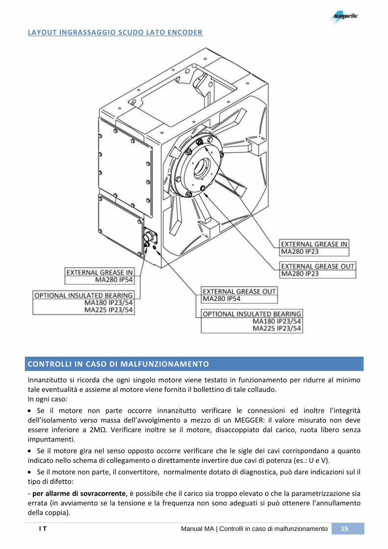
LAYOUT INGRASSAGGIO SCUDO LATO ENCODER
CONTROLLI IN CASO DI MALFUNZIONAMENTO
Innanzitutto si ricorda che ogni singolo motore viene testato in funzionamento per ridurre al minimo tale eventualità e assieme al motore viene fornito il bollettino di tale collaudo. In ogni caso:
Se il motore non parte occorre innanzitutto verificare le connessioni ed inoltre l’integrità dell’isolamento verso massa dell’avvolgimento a mezzo di un MEGGER: il valore misurato non deve essere inferiore a 2MΩ. Verificare inoltre se il motore, disaccoppiato dal carico, ruota libero senza impuntamenti.
Se il motore gira nel senso opposto occorre verificare che le sigle dei cavi corrispondano a quanto indicato nello schema di collegamento o direttamente invertire due cavi di potenza (es.: U e V).
Se il motore non parte, il convertitore, normalmente dotato di diagnostica, può dare indicazioni sul il tipo di difetto:
- per allarme di sovracorrente, è possibile che il carico sia troppo elevato o che la parametrizzazione sia errata (in avviamento se la tensione e la frequenza non sono adeguati si può ottenere l’annullamento della coppia).

16 ACCESSORI / COMPONENTI | Manual MA I T
- Se il motore è molto caldo (circa 90°C) è dovuto a:
- elevato assorbimento di corrente causato dal carico eccessivo o da errata parametrizzazione del convertitore (normalmente basta verificare che il motore disaccoppiato dal carico assorba una corrente molto vicina al valore della corrente a vuoto riportata sul bollettino di collaudo da fermo fino alla velocità nominale).
- malfunzionamento dell’elettroventilatore se il senso di rotazione del ventilatore non corrisponde alla direzione indicata dalla freccia applicata sullo stesso (etichetta adesiva) o se funziona a velocità inferiore a quella di targa (errata alimentazione, difetto sul motore del ventilatore).
- ostruzione entrata/uscita aria, se il filtro è molto sporco o è ridotto lo spazio intorno al motore.
- ricircolo dell’aria, se il ventilatore aspira l’aria calda emessa dal motore o da altre fonti di calore.
- problemi sull’avvolgimento, verificare mediante ohmmetro adeguato che i 3 valori di resistenza tra i morseti U,V e W (e/o le correnti di fase) siano uguali tra loro.
ACCESSORI / COMPONENTI
PROTEZIONE TERMICA
E’ possibile prevedere i seguenti sensori di temperatura inseriti nell’avvolgimento (normalmente n°1 sensore su testata lato opposto accoppiamento):
KLIXON (N.C.) È contatto normalmente chiuso che si apre quando viene raggiunta la temperatura di scatto.
Temperatura di scatto : 150 5°C
Tensione nominale : 48Vcc / 230Vca
Max portata del contatto : 6A / 6A (cos=0.6)
SONDA PT100 TIPO R8/3-2F20:
Elemento sensibile al platino che al salire della temperatura varia proporzionalmente il suo valore (a 0°C la resistenza è di 100Ω). La connessione è prevista a 3 fili per rilevare la caduta di tensione su una linea.
Temperatura di lavoro: -50°C + 260°C
Resistenza a 100°C: 970÷1030 Ω
Grado di precisione: classe B, Δt = ± ( 0.3 + 0.005 t ) °C
Taratura: DIN EN 60751
A seguire riportiamo la tabella specifica del valore di resistenza ai capi del sensore in funzione della temperatura misurata:
°C Ω °C Ω °C Ω °C Ω
- 50 80.31 30 111.67 110 142.29 190 172.17
- 40 84.27 40 115.54 120 146.06 200 175.85
- 30 88.22 50 119.40 130 149.83 210 179.52
- 20 92.16 60 123.24 140 153.58 220 183.18
- 10 96.09 70 127.07 150 157.32 230 186.83
0 100.00 80 130.89 160 161.05 240 190.47
10 103.90 90 134.70 170 164.77 250 194.09
20 107.79 100 138.50 180 168.47 260 197.70
RED RED WHITE

I T Manual MA | Protezione termica 17
SONDA KTY84/130: È una resistenza che al salire della temperatura varia proporzionalmente il suo valore (a 0°C la resistenza è di 498Ω). Alla temperatura di 100°C si consiglia una corrente continuativa di 2mA.
Temperatura di lavoro: -40°C + 300°C
Resistenza a 100°C: 970÷1030 Ω
Corrente di misurazione @ 25/300°C: 10/2 mA
A seguire riportiamo la tabella specifica del valore di resistenza ai capi del sensore in funzione della temperatura misurata:
Temperat. °C R min Ω R tipica Ω R max Ω
0 474 498 522
10 514 538 563
20 555 581 607
30 599 626 652
40 645 672 700
50 694 722 750
60 744 773 801
70 797 826 855
80 852 882 912
90 910 940 970
100 970 1000 1030
110 1029 1062 1096
120 1089 1127 1164
130 1152 1194 1235
140 1216 1262 1309
150 1282 1334 1385
160 1350 1407 1463
SONDA PTC TIPO SNM130ES520:
È un termistore “positivo” dove la resistenza nominale (da 20÷550 Ω) aumenta bruscamente ≥1330Ω in prossimità della soglia di temperatura 130°C. Si consiglia una tensione di misura ≥ 2,5Vdc.
Temperatura di reazione nominale: 130 °C (TREF)
Campo di tensione d’esercizio: 2,5 VDC - 30 VDC
Tensione sensore max. consigliata: 2,5 VDC - 7,5 VDC

18 TRASDUTTORE | Manual MA I T
TRASDUTTORE
I trasduttori generalmente montati nei motori MA (EH80K, ERN430, VFS60A, S21 e Resolver) sono ad asse cavo per garantire una buona trasmissione meccanica mantenendo ridotti gli ingombri. Occorre tenere presente che la velocità massima di un encoder dipende dalla propria massima frequenza di funzionamento e dal numero di impulsi/giro come indicato nella seguente formula:
( )
Nel grafico a fianco è raffigurato l’andamento della velocità max degli encoder generalmente montati nei motori MA in funzione del numero impulsi/giro.
A seguito riportiamo la sequenza per lo smontaggio di alcuni trasduttori.
I T Manual MA | Trasduttore 19
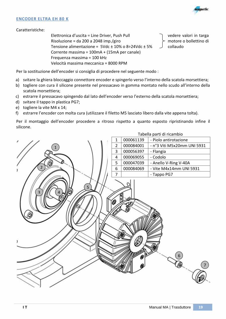
ENCODER ELTRA EH 80 K Caratteristiche:
Elettronica d’uscita = Line Driver, Push Pull Risoluzione = da 200 a 2048 imp./giro Tensione alimentazione = 5Vdc ± 10% o 8÷24Vdc ± 5% Corrente massima = 100mA + (15mA per canale) Frequenza massima = 100 kHz Velocità massima meccanica = 8000 RPM
vedere valori in targa motore o bollettino di collaudo
Per la sostituzione dell’encoder si consiglia di procedere nel seguente modo :
a) svitare la ghiera bloccaggio connettore encoder e spingerlo verso l’interno della scatola morsettiera; b) togliere con cura il silicone presente nel pressacavo in gomma montato nello scudo all’interno della
scatola morsettiera; c) estrarre il pressacavo spingendo dal lato dell’encoder verso l’esterno della scatola morsettiera; d) svitare il tappo in plastica PG7; e) togliere la vite M4 x 14; f) estrarre l’encoder con molta cura (utilizzare il filetto M5 lasciato libero dalla vite appena tolta).
Per il montaggio dell’encoder procedere a ritroso rispetto a quanto esposto ripristinando infine il silicone.
Tabella parti di ricambio
1 000061139 - Piolo antirotazione
2 000084001 - n°3 Viti M5x20mm UNI 5931
3 000056397 - Flangia
4 000069055 - Codolo
5 000047039 - Anello V-Ring V-40A
6 000084069 - Vite M4x14mm UNI 5931
7 - Tappo PG7
1
2
3 5
6
7
4
20 TRASDUTTORE | Manual MA I T
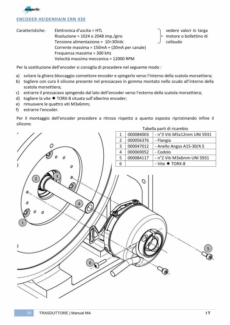
ENCODER HEIDENHAIN ERN 430 Caratteristiche:
Elettronica d’uscita = HTL
Risoluzione = 1024 o 2048 imp./giro Tensione alimentazione = 10÷30Vdc Corrente massima = 150mA + (20mA per canale) Frequenza massima = 300 kHz Velocità massima meccanica = 12000 RPM
vedere valori in targa motore o bollettino di collaudo
Per la sostituzione dell’encoder si consiglia di procedere nel seguente modo :
a) svitare la ghiera bloccaggio connettore encoder e spingerlo verso l’interno della scatola morsettiera; b) togliere con cura il silicone presente nel pressacavo in gomma montato nello scudo all’interno della
scatola morsettiera; c) estrarre il pressacavo spingendo dal lato dell’encoder verso l’esterno della scatola morsettiera; d) togliere la vite TORX-8 situata sull’alberino encoder; e) rimuovere le quattro viti M3x6mm; f) estrarre l’encoder.
Per il montaggio dell’encoder procedere a ritroso rispetto a quanto esposto ripristinando infine il silicone.
Tabella parti di ricambio
1 000084003 - n°3 Viti M5x12mm UNI 5931
2 000056376 - Flangia
3 000047012 - Anello Angus A15-30/4.5
4 000069052 - Codolo
5 000084117 - n°2 Viti M3x6mm UNI 5931
6 - Vite TORX-8
1
2 3
5
4
6

I T Manual MA | Trasduttore 21
ENCODER STEGMANN-SICK VFS 60 A (PROGRAMMABILE) Caratteristiche:
Elettronica d’uscita = TTL, HTL
Risoluzione = da 1 a 65536 imp./giro Tensione alimentazione = 5÷32Vdc Corrente massima = 60mA + (40mA per canale) Frequenza massima = 820 kHz Velocità massima meccanica = 9000 RPM
vedere valori in targa motore o bollettino di collaudo
Per la sostituzione dell’encoder si consiglia di procedere nel seguente modo :
a) svitare la vite “A” del coperchio encoder e staccare con cura il cavo come illustrato nella foto; b) allentare la vite TORX-10 situata sull’alberino encoder; c) rimuovere la vite M5x12mm; d) estrarre l’encoder.
Normalmente non è necessario sostituire il cavo dell’encoder. Se necessario, procedere nel seguente modo:
e) svitare la ghiera bloccaggio connettore e spingerlo verso l’interno della scatola morsettiera; f) togliere con cura il silicone presente nel passacavo in gomma montato nello scudo all’interno della
scatola morsettiera; g) estrarre il passacavo spingendo dal lato dell’encoder verso l’esterno della scatola morsettiera;
Per il montaggio dell’encoder procedere a ritroso rispetto a quanto esposto ripristinando infine il silicone.
Tabella parti di ricambio
1 000084003 - n°3 Viti M5x12mm UNI 5931
2 000056376 - Flangia
3 000047012 - Anello Angus A15-30/4.5
4 000069052 - Codolo
5 000084117 - n°2 Viti M3x6mm UNI 5931
6 - Vite TORX-10
7 - Guaina isolante
1
2 3
5
4
6 7
A

22 TRASDUTTORE | Manual MA I T
ENCODER HENGSTLER S 21
Caratteristiche:
Risoluzione impulsi incrementali = 2048 imp/giro Tensione alimentazione = 5Vdc ± 10% Corrente massima = 120mA Offset Vdc dei segnali d’uscita = 2.5Vdc ± 20% Tensione uscite incrementali e assolute = 1 Vpp Tensione impulso di zero R(+) R(-) ≥ 0.4V Frequenza massima = 500 kHz Velocità massima = 12000 RPM
Per la sostituzione dell’encoder si consiglia di procedere nel seguente modo :
a) svitare le 4 viti M5 x 50 di fissaggio calotta; b) togliere la calotta prestando attenzione nello sfilare contemporaneamente il passacavo in gomma; c) svitare la vite a croce (particolare 6); d) togliere il coperchietto e staccare il connettore delicatamente; e) svitare la vite M5 x 20; f) svitare le 2 viti M3 x 6 di fissaggio encoder; g) estrarre l’encoder con molta cura (utilizzare il filetto M6 lasciato libero dalla vite appena tolta).
Per il montaggio dell’encoder procedere a ritroso rispetto a quanto esposto.
Tabella parti di ricambio
1 000084003 - n°3 Viti M5x12mm UNI 5931
2 000056376 - Flangia
3 000069071 - Codolo
4 000084117 - n°2 Viti M3x6mm UNI 5931
5 - Vite M5x20mm
6 - Vite a croce
1
2
6
3
4
5

I T Manual MA | Trasduttore 23
RESOLVER Per la sostituzione del resolver si consiglia di procedere nel seguente modo : a) togliere con cura il silicone del connettore all’interno della scatola morsettiera; b) se provvisti di apposito estrattore, estrarre i pins spingendoli dall’esterno verso l’interno della
scatola morsettiera, in alternativa utilizzare una pinzetta prestando attenzione a non rovinarli; c) svitare le 4 viti M5 x 50 di fissaggio calotta; d) togliere la calotta prestando attenzione nello sfilare contemporaneamente il passacavo in gomma; e) svitare le 3 viti M5 x 8 e togliere lo statore resolver; f) svitare i due dadi esagonali M12 x 1; g) togliere il rotore resolver.
Per il montaggio del resolver procedere a ritroso rispetto a quanto esposto ripristinando infine il silicone.
Tabella parti di ricambio
1 000084003 - n°3 Viti M5x12mm UNI 5931
2 000056336 - Flangia
3 000069049 - Codolo
4 000088002 - n°3 Rosette in rame 5,3x9,5mm UNI 6592
5 000084136 - n°3 Viti M5x8mm UNI 5931
6 000096017 - n°2 dadi in ottone M12x1mm
1
2
6
3
4
5
24 RELÈ ANEMOSTATICO | Manual MA I T
RELÈ ANEMOSTATICO
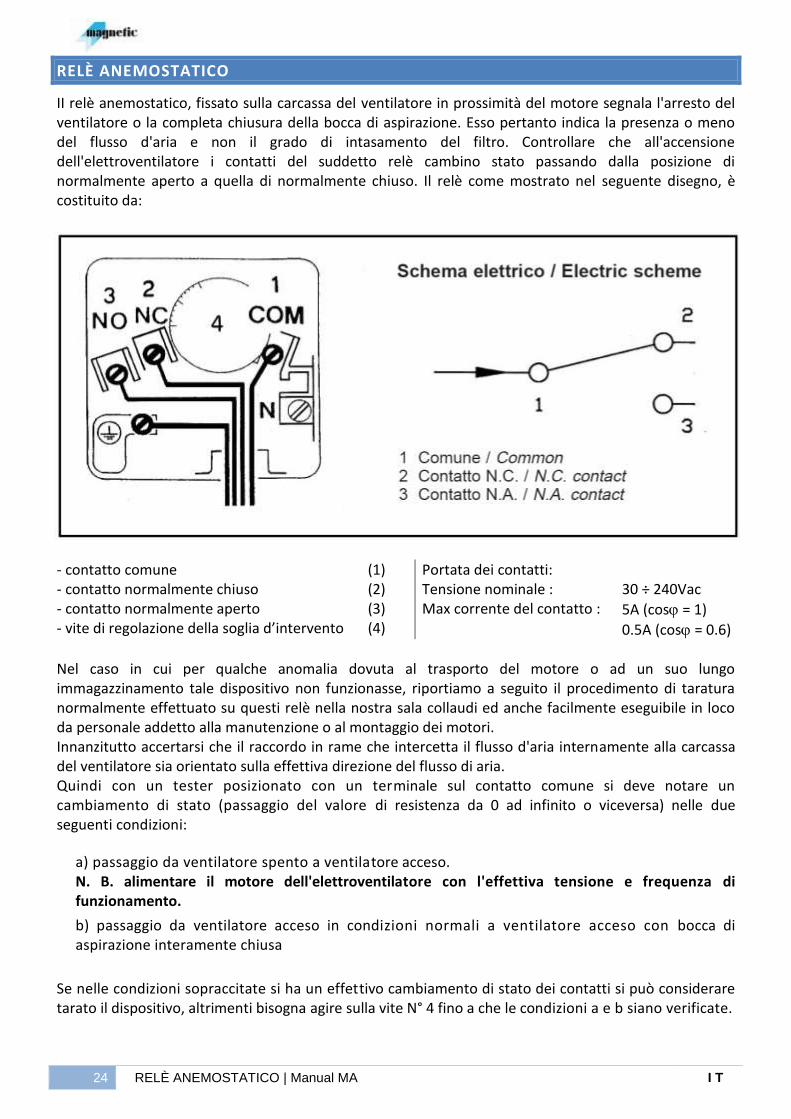
II relè anemostatico, fissato sulla carcassa del ventilatore in prossimità del motore segnala l'arresto del ventilatore o la completa chiusura della bocca di aspirazione. Esso pertanto indica la presenza o meno del flusso d'aria e non il grado di intasamento del filtro. Controllare che all'accensione dell'elettroventilatore i contatti del suddetto relè cambino stato passando dalla posizione di normalmente aperto a quella di normalmente chiuso. Il relè come mostrato nel seguente disegno, è costituito da:
- contatto comune - contatto normalmente chiuso - contatto normalmente aperto - vite di regolazione della soglia d’intervento
(1) (2) (3) (4)
Portata dei contatti: Tensione nominale : Max corrente del contatto :
30 ÷ 240Vac
5A (cos = 1)
0.5A (cos = 0.6) Nel caso in cui per qualche anomalia dovuta al trasporto del motore o ad un suo lungo immagazzinamento tale dispositivo non funzionasse, riportiamo a seguito il procedimento di taratura normalmente effettuato su questi relè nella nostra sala collaudi ed anche facilmente eseguibile in loco da personale addetto alla manutenzione o al montaggio dei motori. Innanzitutto accertarsi che il raccordo in rame che intercetta il flusso d'aria internamente alla carcassa del ventilatore sia orientato sulla effettiva direzione del flusso di aria. Quindi con un tester posizionato con un terminale sul contatto comune si deve notare un cambiamento di stato (passaggio del valore di resistenza da 0 ad infinito o viceversa) nelle due seguenti condizioni:
a) passaggio da ventilatore spento a ventilatore acceso. N. B. alimentare il motore dell'elettroventilatore con l'effettiva tensione e frequenza di funzionamento.
b) passaggio da ventilatore acceso in condizioni normali a ventilatore acceso con bocca di aspirazione interamente chiusa
Se nelle condizioni sopraccitate si ha un effettivo cambiamento di stato dei contatti si può considerare tarato il dispositivo, altrimenti bisogna agire sulla vite N° 4 fino a che le condizioni a e b siano verificate.
IT Manual MA | SCHEMA PER IL COLLEGAMENTO DEI MOTORI 'MA' 25
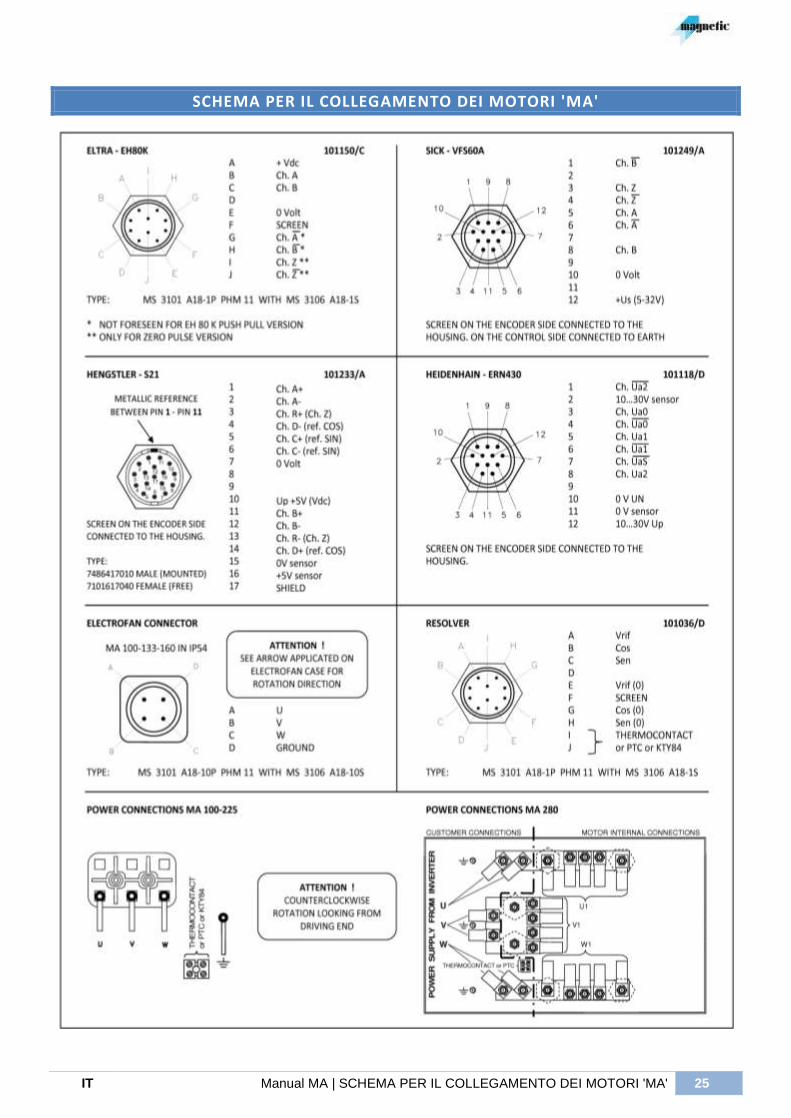
SCHEMA PER IL COLLEGAMENTO DEI MOTORI 'MA'
26 COLLEGAMENTI | Manual MA I T
COLLEGAMENTI
Il collegamento elettrico deve rispettare le norme di sicurezza vigenti e verificare che i dati di targa siano conformi alle caratteristiche del circuito cui il motore deve essere collegato.
Evitare di collegare il motore direttamente alla rete trifase, tale operazione può provocare la distruzione del motore !
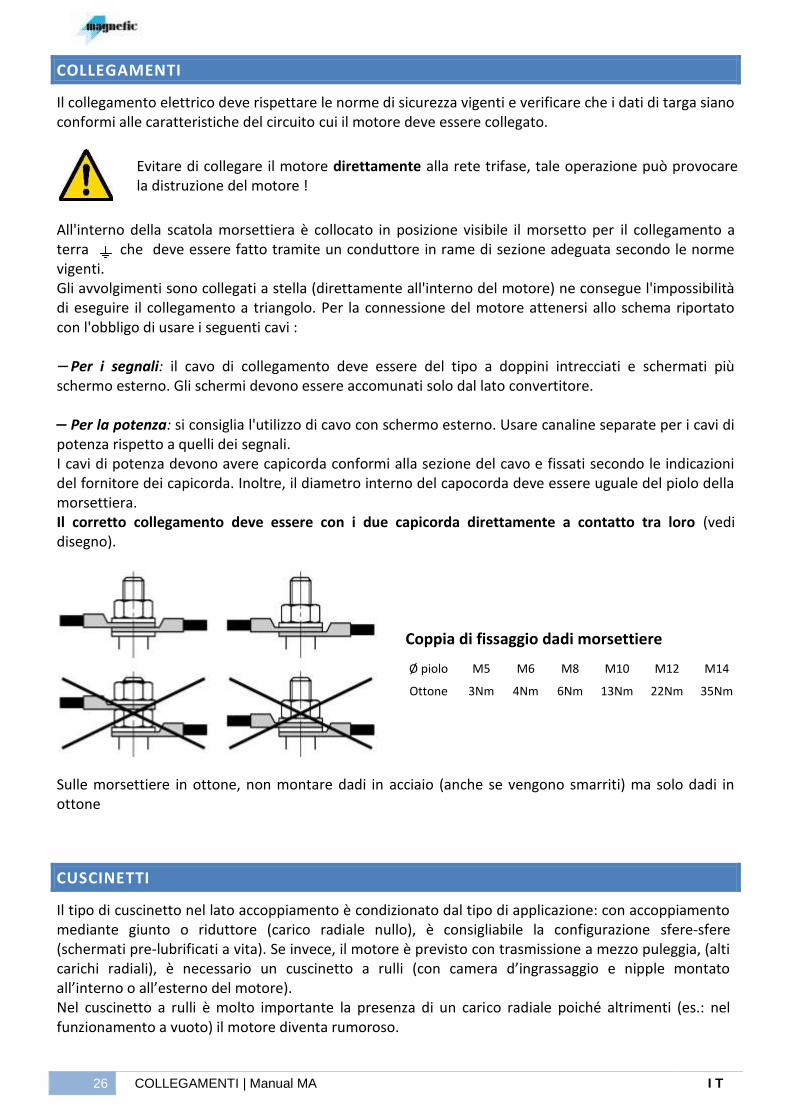
All'interno della scatola morsettiera è collocato in posizione visibile il morsetto per il collegamento a terra che deve essere fatto tramite un conduttore in rame di sezione adeguata secondo le norme vigenti. Gli avvolgimenti sono collegati a stella (direttamente all'interno del motore) ne consegue l'impossibilità di eseguire il collegamento a triangolo. Per la connessione del motore attenersi allo schema riportato con l'obbligo di usare i seguenti cavi : Per i segnali: il cavo di collegamento deve essere del tipo a doppini intrecciati e schermati più schermo esterno. Gli schermi devono essere accomunati solo dal lato convertitore. Per la potenza: si consiglia l'utilizzo di cavo con schermo esterno. Usare canaline separate per i cavi di potenza rispetto a quelli dei segnali. I cavi di potenza devono avere capicorda conformi alla sezione del cavo e fissati secondo le indicazioni del fornitore dei capicorda. Inoltre, il diametro interno del capocorda deve essere uguale del piolo della morsettiera. Il corretto collegamento deve essere con i due capicorda direttamente a contatto tra loro (vedi disegno).
Coppia di fissaggio dadi morsettiere
Sulle morsettiere in ottone, non montare dadi in acciaio (anche se vengono smarriti) ma solo dadi in ottone
CUSCINETTI
Il tipo di cuscinetto nel lato accoppiamento è condizionato dal tipo di applicazione: con accoppiamento mediante giunto o riduttore (carico radiale nullo), è consigliabile la configurazione sfere-sfere (schermati pre-lubrificati a vita). Se invece, il motore è previsto con trasmissione a mezzo puleggia, (alti carichi radiali), è necessario un cuscinetto a rulli (con camera d’ingrassaggio e nipple montato all’interno o all’esterno del motore). Nel cuscinetto a rulli è molto importante la presenza di un carico radiale poiché altrimenti (es.: nel funzionamento a vuoto) il motore diventa rumoroso.
Ø piolo M5 M6 M8 M10 M12 M14
Ottone 3Nm 4Nm 6Nm 13Nm 22Nm 35Nm
IT Manual MA | Dispositivo messa a terra dell’albero 27
Se nel breve periodo dalla messa in servizio o dall’ultima sostituzione dei cuscinetti si manifestasse un’elevata rumorosità potrebbe indicare un ridotto ingrassaggio, attenersi a quanto indicato nelle tabelle successive. Questo effetto può essere anche indice di correnti d’albero: queste correnti si possono manifestare nei motori a causa dell’alimentazione da convertitori in PWM dove a causa delle elevate frequenze di commutazione, assumono rilevanza le capacità parassite presenti nel motore tra statore e rotore. Si generano delle correnti impulsive che circolano nel circuito composto dal rotore, cuscinetti e statore e verso la massa. Per ridurre tale fenomeno, è necessario interrompere il circuito della corrente utilizzando un cuscinetto speciale isolato con un rivestimento ceramico. Una parte delle correnti d’albero si richiude attraverso il cuscinetto verso la massa quindi per creare un percorso alternativo al cuscinetto è possibile prevedere un dispositivo di messa a terra dell’albero. Trattasi di un sistema a spazzole che collega elettricamente il rotore al resto della macchina.
DISPOSITIVO MESSA A TERRA DELL’ALBERO
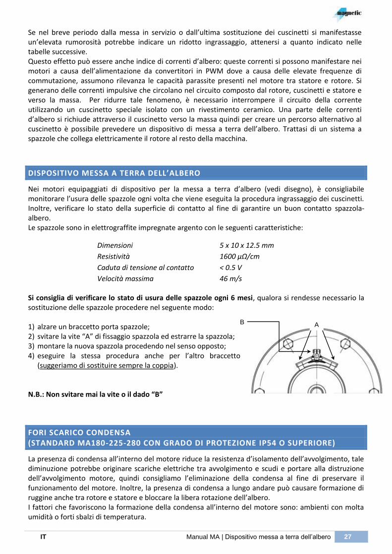
Nei motori equipaggiati di dispositivo per la messa a terra d’albero (vedi disegno), è consigliabile monitorare l’usura delle spazzole ogni volta che viene eseguita la procedura ingrassaggio dei cuscinetti. Inoltre, verificare lo stato della superficie di contatto al fine di garantire un buon contatto spazzola-albero. Le spazzole sono in elettrograffite impregnate argento con le seguenti caratteristiche:
Dimensioni 5 x 10 x 12.5 mm
Resistività 1600 µΩ/cm
Caduta di tensione al contatto < 0.5 V
Velocità massima 46 m/s
Si consiglia di verificare lo stato di usura delle spazzole ogni 6 mesi, qualora si rendesse necessario la sostituzione delle spazzole procedere nel seguente modo:
1) alzare un braccetto porta spazzole; 2) svitare la vite “A” di fissaggio spazzola ed estrarre la spazzola; 3) montare la nuova spazzola procedendo nel senso opposto; 4) eseguire la stessa procedura anche per l’altro braccetto
(suggeriamo di sostituire sempre la coppia).
N.B.: Non svitare mai la vite o il dado “B”
FORI SCARICO CONDENSA (STANDARD MA180-225-280 CON GRADO DI PROTEZIONE IP54 O SUPERIORE)
La presenza di condensa all’interno del motore riduce la resistenza d’isolamento dell’avvolgimento, tale diminuzione potrebbe originare scariche elettriche tra avvolgimento e scudi e portare alla distruzione dell’avvolgimento motore, quindi consigliamo l’eliminazione della condensa al fine di preservare il funzionamento del motore. Inoltre, la presenza di condensa a lungo andare può causare formazione di ruggine anche tra rotore e statore e bloccare la libera rotazione dell’albero. I fattori che favoriscono la formazione della condensa all’interno del motore sono: ambienti con molta umidità o forti sbalzi di temperatura.
A B

28 FRENO | Manual MA I T
I fori della condensa (chiusi da tappi filettati PG7) si trovano nella parte bassa del motore (rif. alla forma B3). Questi tappi devono essere aperti ogni 6 mesi e poi richiusi (la mancanza del rimontaggio dei tappi non garantisce il grado di protezione del motore). Prima di avvitare i tappi, consigliamo di pulirli accuratamente così come i fori della condensa.
N.B.: in caso di forte umidità e di sbalzi notevoli della temperatura, l’operazione deve essere eseguita più spesso.
È possibile lasciare il motore senza i tappi della condensa solamente se non viene compromesso il grado di protezione del motore.
Fori scarico condensa
Qualora il motore non fosse montato nella posizione B3, e non sono presenti fori aggiuntivi per la condensa richiesti in fase ordine del motore, la Magnetic declina ogni responsabilità sulla durata di funzionamento del motore poiché i fori di condensa, non trovandosi nella parte più bassa del motore, non svolgono il loro compito di scarico acqua.
FRENO
Il freno è di tipo elettromeccanico a molle, a bassa inerzia con azione frenante per mancanza d’alimentazione, ha una struttura robusta che permette una buona dissipazione del calore.
Motore MA100 MA133 MA160 MA180 MA225 MA280
Tipo di freno K5 NIA2 K7 K7/D1 NIA10 K9 K9/D
1 NIA25 K9/D
1 NIA40 NFF100 NIA63 NFF100 NFF250
Coppia frenante Statica (Nm)
40 20 90 180 100 300 600 250 600 400 1000 630 1000 2500
Velocità max Motore (RPM)
3600 5300 3600 3600 4100 1800 1800 3500 1800 3200 2800 3000 2800 1900
Tensione alimentaz. (Vdc)
24 24 24 24 24 24 24 24 24 24 110 24 110 110
Potenza (W) 45 80 55 55 110 65 65 149 65 170 270 249 270 400
Massimo lavoro con 1interv./ora (kJ)
27 24 38 100 90 90 215 180 215 320 330 360 330 500
Traferro massimo (mm)
0.7 1.0 0.7 0.7 1.2 0.7 0.7 1.2 0.7 1.3 1.8 1.5 1.8 1.8
1) ATTENZIONE: nel montaggio in verticale (V1, V3 ecc.) sono previsti in versione speciale.
Il freno durante l’intervento genera calore in funzione dell’inerzia da frenare e dalla velocità di rotazione, quindi è importante verificare che il lavoro sviluppato dal freno durante la frenata non superi il limite riportato in tabella.
Il lavoro (L) si determina con la seguente equazione :
( )
Jm = inerzia motore Jf = inerzia freno Jc = inerzia carico n = velocità L = Lavoro
(Kgcm2) (Kgcm2) (Kgcm2) (RPM) (kJ)
IT Manual MA | Freno 29
Se il numero d’interventi/ora è maggiore di 1, il massimo lavoro dissipabile diminuisce in funzione del numero di manovre, quindi per particolari richieste contattare ufficio commerciale MAGNETIC.
FRENO “NIA”
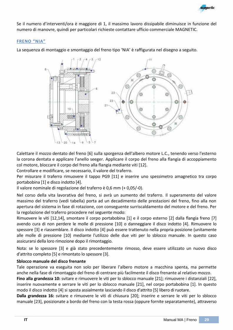
La sequenza di montaggio e smontaggio del freno tipo ‘NIA’ è raffigurata nel disegno a seguito.
Calettare il mozzo dentato del freno [6] sulla sporgenza dell'albero motore L.C., tenendo verso l'esterno la corona dentata e applicare l'anello seeger. Applicare il corpo del freno alla flangia di accoppiamento col motore, bloccare il corpo del freno alla flangia mediante viti [12]. Controllare e modificare, se necessario, il valore del traferro. Per misurare il traferro rimuovere il tappo PG9 [11] e inserire uno spessimetro amagnetico tra corpo portabobina [1] e disco indotto [4]. Il valore nominale di regolazione del traferro è 0,6 mm (+ 0,05/-0).
Nel corso della vita lavorativa del freno, si avrà un aumento del traferro. Il superamento del valore massimo del traferro (vedi tabella) porta ad un decadimento delle prestazioni del freno, fino alla non apertura del sistema in fase di rotazione, con conseguente surriscaldamento del motore e del freno. Per la regolazione del traferro procedere nel seguente modo: Rimuovere le viti [12,14], smontare il corpo portabobina [1] e il corpo esterno [2] dalla flangia freno [7] avendo cura di non perdere le molle di pressione [10] o danneggiare il disco indotto [4]. Rimuovere lo spessore [3] e riassemblare. II disco indotto [4] può essere trattenuto nella propria posizione (unitamente alle molle di pressione [10] mediante l'utilizzo delle due viti per lo sblocco manuale. In questo caso assicurarsi della loro rimozione dopo il rimontaggio.
Nota: se lo spessore [3] e già stato precedentemente rimosso, deve essere utilizzato un nuovo disco d'attrito completo [5] e rimontato lo spessore [3].
Sblocco manuale del disco frenante Tale operazione va eseguita non solo per liberare l'albero motore a macchina spenta, ma permette anche nella fase di rimontaggio del freno di centrare più facilmente il disco frenante al relativo mozzo. Fino alla grandezza 10: svitare e rimuovere le viti per lo sblocco manuale [21]; rimuovere i distanziali [22], inserire nuovamente e serrare le viti per lo sblocco manuale [21], nel corpo portabobina [1]. In questo modo il disco indotto [4] si sposta assialmente lasciando il disco d'attrito [5] libero di ruotare. Dalla grandezza 16: svitare e rimuovere le viti di chiusura [20]; inserire e serrare le viti per lo sblocco manuale [23], posizionate a bordo del freno con la testa rossa (oppure fornite separatamente), attraverso

30 FRENO | Manual MA I T
il corpo portabobina [1], nel disco indotto [4] che in questo modo si sposta assialmente lasciando il disco d'attrito [5] libero di ruotare.
FRENO “K”
La sequenza di montaggio e smontaggio del freno tipo ‘K’ è raffigurata nel disegno a seguito.
Posizionare dapprima il mozzo [5] sull'albero motore, quindi inserire nell'apposita sede predisposta sul mozzo l'o-ring [6]. Inserire quindi il disco [4] sul mozzo. Posizionare quindi l'ancora [2] e l'elettromagnete [1], in cui devono essere inserite le molle di coppia. Serrare le viti di fissaggio [9] con una chiave dinamometrica a brugola con i valori riportati (M4=2.8 Nm; M5=5.6 Nm; M6=9.6 Nm; M8=23.2 Nm; M10=46.4Nm) nella flangia di supporto del freno. Controllare e modificare, se necessario, il valore del traferro. La regolazione del traferro avviene agendo sui registri [8], dopo aver allentato le viti di fissaggio [9]. Se tale operazione viene eseguita alla fine di un periodo lavorativo assicurarsi che il corpo del freno non sia surri-scaldato. Il valore nominale di regolazione del traferro è 0,2 mm (+ 0,05/-0). Il massimo valore accettabile per il traferro è di 0,7 mm. Se tale valore viene superato a causa del consumo del materiale d'attrito, le prestazioni del freno possono essere modificate.
Inoltre il superamento del valore massimo di traferro porta ad un decadimento delle prestazioni del freno, fino alla non apertura del sistema in fase di rotazione, con conseguente surriscaldamento del motore e del freno.
TENSIONE ALIMENTAZIONE FRENO
Il freno NFF100 deve essere alimentato con una tensione alternata monofase a 110V, mentre tutti i freni serie NIA e K devono avere una alimentazione in corrente continua ed il collegamento elettrico alla rete deve essere realizzato secondo lo schema sotto indicato.

EN Manual MA | MA series asynchronous vectorial servomotors 31
MA series asynchronous vectorial servomotors
Operation and maintenance manual
32 INDEX | Manual MA E N
INDEX
GENERAL WARNINGS 33
AUTHORIZED STAFF 33
SAFETY 33
REFERENCE NORMS 34
RECEPTION - STORAGE 35
ELECTRICAL TESTS 35
COUPLING / POSITIONING 36
SETTING AT WORK 38
OPERATION 39
MAINTENANCE 40
SPARE PARTS 40
REPLACEMENT OF BEARINGS MA 100÷225 40
REPLACEMENT OF BEARINGS MA 280 41
BEARINGS MAINTENANCE TABLE 42
LAYOUT OF GREASE OF DE SIDE SHIELD 43
LAYOUT OF GREASE OF NDE SIDE SHIELD 44
TESTS IN CASE OF BAD OPERATING 44
ACCESSORIES / COMPONENTS 45
THERMAL PROTECTION 45
KLIXON (N.C.) 45
PT100 SENSOR TYPE R8/3-2F20: 45
KTY84/130 SENSOR: 46
PTC SENSOR TYPE SNM130ES520: 46
TRANSDUCER 47
ENCODER ELTRA EH 80 K 48
ENCODER HEIDENHAIN ERN 430 49
ENCODER STEGMANN-SICK VFS 60 A (PROGRAMMABLE) 50
ENCODER HENGSTLER S 21 51
RESOLVER 52
ANEMOSTATIC RELAY 53
CONNECTIONS DIAGRAM FOR ‘MA’ MOTORS 54
CONNECTIONS 55
BEARINGS 55
SHAFT GROUNDING SYSTEM 56
CONDENSATE DRAIN HOLES 56
BRAKE 57
“NIA” BRAKE 58
“K” BRAKE 59
BRAKE POWER SUPPLY 59

E N Manual MA | GENERAL WARNINGS 33
GENERAL WARNINGS
This manual only refers to standard products listed in our catalogue. MAGNETIC will not be responsible for problems or accidents due to no application of the instructions indicated in the present manual. The main points concerning the correct use of MA series asynchronous vectorial servomotors with squirrel-cage rotor, are listed hereby.
AUTHORIZED STAFF
This manual is for AUTHORIZED STAFF that must know and respect all the national safety norms and the existing policies concerning the low voltage installations. The following skills are required:
Transport only staff with notions about materials handling
Mechanical assembly only qualified mechanics.
Electrical connection only specialized electricians
Motor set up only qualified technicians with in-depth notions of mechanics, electrical engineering and drive technology
SAFETY
The motors have parts under voltage and moving parts. It is therefore necessary to follow some norms in order to avoid dangerous situations. The handling, the starting up, the use and the eventual repair must be carried out by AUTHORIZED STAFF and always in accordance with the following instructions:
The authorized staff must know the norms about installation, use and maintenance of the motor and must have read all this use and maintenance manual carefully.
The authorized staff must know all the technical details, specifications and electrical connections concerning the motor to be installed.
All operations are not allowed to unqualified operators.
In order to reduce any action, which could damage the motor or the operators or the things nearby, the following remarks must be observed:
Take particular care during the placing of the machine in order to avoid accidental falls The motor shaft is free to run so it must not be used for the handling. Lift and/or move the motors only using the eyehooks assembled on the motor or others appropriate. Do not approach to the rotating parts (for example: motor shaft). Use protective clothing during the mounting of mechanical components on the shaft end (presence
of sharp edges next to the keyway).

34 REFERENCE NORMS | Manual MA E N
Before testing the machine ensure to have the adequate protections around the rotating parts (joints, etc.).
Check also the screws for fixing the motor to the machine.
Check the absence of any tension on the system before proceeding with the electrical connection of the motor.
Check that the electrical cables are not damaged because of the mounting, that they are far from any rotating part and that they have not to support any mechanical effort.
Connect the grounding of the motor case to a mass potential of the machine and check the presence of an effective low impedance, otherwise the safety of the people could be compromised.
Control the fixing of the screws or of the nuts of the electrical terminal blocks, before starting the operation of the motor.
Before proceeding with the motor supply close the cover of the terminal box Do not disconnect any connector during the operation or when the electrical panel is switched on.
In the closed not ventilated version (TENV) the temperature of the motors surface could reach or exceed 100° C. Therefore keep far from motor any object that could burn or be damaged at such a high temperature.
Before touching the motor, wait that a temperature lower than 40°C is reached.
Do not use the motor as a support base for people or parts of the equipment
REFERENCE NORMS
The asynchronous vectorial motors MA series are manufactured in accordance with norms concerning electrical rotating machines.
Main norms applied for this kind of machines (*): CEI EN 60034-1 Rating and performance CEI EN 60034-5 Degrees of protection provided by the integral design of rotating electrical machines (IP code) - Classification CEI EN 60034-6 Methods of cooling (IC code) CEI EN 60034-7 Classification of the types of construction and mounting arrangements (IM code) CEI EN 60034-8 Terminal marking and direction of rotation CEI EN 60034-11 Thermal protection: requirements for the use of protection thermal sensors in the stator windings CEI EN 60034-14 Mechanical vibrations of certain machines with shaft height 56 mm and higher - Measurement, evaluation and limits of vibration severity CEI CLC/TS EN 60034-25 Guidance for the design and performance of a.c. motors specifically designed for converter supply
(*) CEI Italian norms numbers correspond to European numeration EU CENELEC and international IEC.
E N Manual MA | RECEPTION - STORAGE 35
The products indicated in the present manual are manufactured in compliance with EU directives about “low voltage” (2006/95/EC)
The motors must be installed in accordance with the instructions supplied by the manufacturer: before proceeding with the starting up it is necessary to check that the machine, where the motor will be installed, is compliant with the reference norms.
RECEPTION - STORAGE
All motors are subject to an accurate test and check before shipment. Each motor is supplied with a test certificate where all the specifications of the motor and the relative accessories are listed. On arrival, it is advisable to check that the motors have not been damaged during transport; any defect must be immediately notified to Magnetic. If the motors are not installed immediately, they must be stocked in a clean and dry room, without vibrations which may damage the bearings and they must be protected against sudden temperature changes which might cause condensate. The shaft end shall be checked and, if necessary, the protective varnish should be touched up with suitable anticorrosive products. If the motors have been stored for a long time at low temperature, keep them at room temperature for a few days to eliminate any condensate. In this case please follow the instructions of the following paragraph.
ELECTRICAL TESTS
Before the starting up and after long periods of inactivity or storage we recommend you the following checks:
- Check the homogeneity of the 3 combinations of phase-to-phase resistance and the conformity with the value indicated in the test certificate (the maximum difference allowed among the three resistances should not exceed approximately 3%).
We suggest you to perform the measurement through a milliohmeter (NO multimeter, because the resistance is too low and an ordinary tester does not assure an adequate sensitivity). Check also that the milliohmeter uses a measuring current in dc (no pulsating or AC).
- The resistance value of the thermal protection circuit must be close to zero (NC contact). In this case a normal multimeter can be used. Set the scale in Ohm and measure at the ends of the protector a resistance ≤ 0.1Ω (Klixon with normally closed contact). In case the thermal protection is PT100, KTY84 or PTC, set the scale in Ohm and compare the noticed resistance value with the tables of paragraph: “THERMAL PROTECTION”.
- Check that the winding insulation towards ground and towards the thermal protector is higher than 2
M by using a MEGGER tool with test voltage 500 or 1000 Vdc. This measurement cannot be performed by using a multimeter, but it is imperative to use a Megger tool with an adequate test voltage. Measure between one of the 3 phases and the ground screw, then between a thread of the thermal protector and the ground screw and finally between a phase and a thread of the thermal protector. After each measurement it is necessary to discharge the residual voltage due to the “capacitive effect” through a cable between the two heads where the measurement has just been performed.
If you do not notice the indicated value, this means that the winding is wet and must be dried by a specialized company.

36 COUPLING / POSITIONING | Manual MA E N
COUPLING / POSITIONING
This operation is rather delicate and requires extreme accuracy, to ensure a good motor operation. To place the motor with feet (IM1001-B3 or equivalent) it is indispensable that the base surface is perfectly in flat to avoid deformations and/or breaches of the shields: if necessary insert opportunely metallic-sheet under the feet to fill the air gap. The transmission unit must be assembled by using the threaded hole on the top of the motor shaft with a special tool. Any hit that might harm the bearings must be avoided.
N.B. The motor rotors are balanced through half-key, then full shaft and A degree. Transmission units (gears, half joints, pulleys) must therefore be balanced by half-key (unthrottled hole). The direct coupling through joints must be done in such a way as to ensure a good alignment, otherwise strong vibrations, irregular motion and axial thrusts on the bearings may take place and compromise their life. In consideration of the importance of the alignment, we recommend the use of comparators or Laser instruments foreseen for the check of this alignment. If during the operation there are noise or vibrations on the motor or on the bearings, we recommend to improve / reduce the misalignment by appropriate position metal shims. In case of direct coupling in oil bath, make sure that the oil ring (with spring), which is supplied upon request, is foreseen. The ring must not be mounted in case of dry coupling. We advise you to check the value of the radial load by using the below formula and comparing this to the tables shown in the following page.
where: Fr = radial load N P = motor rating in kW n = motor rated speed in RPM D = pulley’s diameter in mm
K = tension factor indicated by the pulley manufacturer and corresponding averagely to:
k = 1.0 for toothed belts k = 2.3 for V belts k = 3.8 for flat belts
If the radial power value, calculated with this formula, results higher than the one indicated in the tables, it is necessary to modify its parameters (to increase the pulley’s diameter, to modify the position of the power barycenter, type and number of belts…) or contact our sales department. Moreover It is advisable to measure the temperature and the bearings vibrations every 2000 working hours in order to evidence eventual deviation of the values and solve. In the below listed tables you will find the maximum permissible radial loads for a theoretic 20.000 hours long bearing life on the driving end.
The type of bearing is indicated at paragraph “Bearings”.

E N Manual MA | COUPLING / POSITIONING 37
MOTORE / MOTOR MA 100
X RPM
200 500 1000 1500 2000 2500 3000 4000 5000
[ mm ] Fr [ daN ]
0 557 407 315 269 241 220 205 182 166
40 479 350 275 239 215 199 186 167 152
60 448 327 257 223 201 186 174 157 145
80 379 307 241 209 189 175 163 148 136
MOTORE / MOTOR MA 133
X RPM
200 500 1000 1500 2000 2500 3000 4000 5000
[ mm ] Fr [ daN ]
0 1075 806 641 560 507 470 441 398 369
50 944 709 569 500 456 425 400 364 337
80 723 661 531 466 425 396 373 339 316
110 577 577 497 437 398 371 349 318 296
MOTORE / MOTOR MA 160
X RPM
200 500 1000 1500 2000 2500 3000 4000 5000
[ mm ] Fr [ daN ]
0 1667 1239 984 858 778 720 676 610 563
50 1108 1108 914 799 724 671 629 568 524
80 843 843 843 762 694 644 604 546 503
110 681 681 681 681 661 614 578 525 484
MOTORE / MOTOR MA 180
X RPM
200 500 1000 1500 2000 2500 3000 4000 5000
[ mm ] Fr [ daN ]
0 3168 2365 1888 1652 1501 1392 1309 1186 -
50 1584 1584 1584 1550 1410 1308 1229 1114 -
90 1099 1099 1099 1099 1099 1099 1099 1062 -
140 797 797 797 797 797 797 797 797 -
MOTORE / MOTOR MA 225
X RPM
200 500 1000 1500 2000 2500 3000 4000 5000
[ mm ] Fr [ daN ]
0 3054 2242 1760 1521 1368 1259 1174 - -
50 2881 2138 1678 1450 1304 1200 1119 - -
90 1653 1653 1618 1398 1258 1157 1079 - -
140 1079 1079 1079 1079 1079 1079 1033 - -
MOTORE / MOTOR MA 280
X RPM
200 500 1000 1500 2000 2500 3000 4000 5000
[ mm ] Fr [ daN ]
0 4853 3580 2823 2450 2210 2038 - - -
60 4587 3405 2686 2330 2102 1939 - - -
120 3272 3216 2560 2222 2005 1849 - - -
210 2076 2076 2076 2056 1865 1728 - - -

38 SETTING AT WORK | Manual MA E N
SETTING AT WORK
Before the first start, it is necessary to check what follows:
-check that the fan supply voltage is the same as that shown on the plate (standard values are shown on the following table) and that the direction of rotation corresponds to the arrow on the casing.
-In case of ventilation through duct connection, make sure that the fan specifications are the same or bigger than those listed in the table:
Motor Cooling version
Nominal power
kW@50Hz
Voltage [Vrms]
Current [Arms]
Noise. [dBA]
1
Voltage [Vrms]
Current [Arms]
Noise [dBA]
1 Air flow
[m³/h] Pressure
[mmH2O]
Frequency 50 Hz Frequency 60 Hz
MA 100 IP54-PVAP 0.045 345÷440 200÷255
0.19 0.33
66 345÷460 200÷265
0.12 0.21
70 220 12
MA 133 IP54-PVAP 0.11 345÷480 200÷275
0.34 0.59
74 345÷480 200÷255
0.31 0.54
78 720 17
MA 133 IP23-PVA 0.37 315÷500 180÷290
1.1 1.82
75 380÷600 215÷350
1.1 1.82
79 930 93
MA 160 IP54-PVAP 0.166 380÷400 0.44 78 380÷440 0.5 80 1100 21
MA 160 IP23-PVA 1.1 300÷460 175÷265
2.6 4.5
78 360÷510 210÷290
2.6 4.5
82 1300 125
MA 180 IP54/IP23-PVA IP54-PVAP2
2.2 315÷400 180÷230
4.8 8.3
80 380÷480 220÷275
4.8 8.3
84 2200 120
MA 2252 IP54/IP23-PVA 3.0
380÷400 220÷230
6.0 10.4
86 460÷480 265÷275
6.0 10.4
86 3300 315
MA 2802 IP54/IP23-PVA 4.0
380÷400 220÷230
6.5 11.3
86 460÷480 265÷275
6.5 11.3
86 3900 285
1) referred to 400V and to the average of the measurements effected at 1 m. 2) Only for size MA225 and MA280 different fans are foreseen for 50Hz and 60Hz.
-After long periods of inactivity, check that there are not foreign objects inside the fan which could stop the rotation of the fan.
-The motors must be installed in such a way as not to hinder the circulation of the cooling air on the
inlet and outlet , we recommend a minimum distance ( 250 mm) between the fan and other machine parts.
-Besides, check that the exhaust air (hot air) is not sucked again by the fan, because this may affect the motor cooling. WARNING: Leave the fan running for more than 30' after the motor is stopped, to avoid the overheating of the transducer and of the bearings.
- The coupling must be performed by means of the motor feet and flange, by avoiding to fix or put weights on and/or beside the stator.
- Check that the hole closing plates for the fixing of L.O. shield feet are closed.
- If the motor is B5 type and it is installed horizontally, it is advisable to use a peg or head frame to support the NDE shield feet so that the motor does not bend.

E N Manual MA | Operation 39
-During the set-up of the machine, check through an oscilloscope that there are no high values (and gradients, dv/dt) of voltage at the heads of the motor terminal box due to the fast commutation of the IGBT of the inverter and to situations of long or particular wirings: there could be very high voltage peaks (kV) and it could be necessary to take countermeasures (such as the use of inductances or filters), in order to reduce this phenomenon.
The measurement must be performed by qualified personnel by using proper equipment. The above figure shows a typical display of the phenomenon.
OPERATION
All motors have 4 poles, that means the speed (at no-load condition) is linked to the frequency by the simplified relation:
30
nfo
On load, the supply frequency must be increased by the slip 'fs' to keep constant the speed, this value depends on the load (torque, T) of the motor as follows:
Tn
Tfsnfs
This ratio is valid in the operation at constant torque while, for constant power regulation, it becomes:
nn
n
Tn
Tfsnfs
The supply frequency of the motor is given by the sum of the value ‘fo’ and ‘fs’ (see the plate or the motor catalogue for the value at the nominal speed ‘nn’). Example: MA 133 M-F1 Fn=51.3Hz n=1500RPM, you can deduce fo=50Hz and then Fsn=1.3Hz. We remind you that the slip increases according to the temperature of the motor (up to 37%): the showed values refer to the maximum temperature. As to the voltage, the value depends on the frequency (therefore on the speed) and it is worth:
f
V
fn
Vn
for constant torque regulation. This formula is approximate since it should be reported to that part of the voltage that determines the flux from which however it differs of few percent points because of the voltage drops (error becomes elevated at low speed). At nominal speed and load, the voltage must be equal to 'Vn' to obtain the performance showed on the motor plate. In constant power regulation, the frequency increase causes always higher voltage drops that require a higher available voltage at the motor terminals. The nmax1 value is therefore given by the highest voltage available from the inverter: it is typical to consider a sinusoidal voltage at the motor of 360VRMS at a net voltage of 380÷400VRMS. The voltage difference between input and output of the converter depends on the drop at the IGBT heads, on the type of modulation and on a voltage margin foreseen for overloads. Besides the voltage, the motor performance depends on the inverter: for example the dynamic behaviour depends on the calculus algorithm used (scalar V/f or FOC), while the noise and the losses depend on the inverter switching frequency.
40 MAINTENANCE | Manual MA E N
MAINTENANCE
In order to assure a long life to the machines it is necessary to follow some rules:
- If the motor is equipped with greaser, follow the intervals specified on the motor plate, taking care of old grease is forced out through the expected steps.
- After the first 3 months of operation : verify that noise and vibrations are not increased (otherwise there could be problems mainly related to the bearings state); check the functionality of the fan and the filter conditions (when expected, replace if necessary).
- Every 12 months: decouple the machine from to plant to verify that the rotor is free to rotate without jamming and without abnormal noise; electrically disconnect the machine to check the insulation (par. ELECTRICAL TESTS) ; verify the functionality of the fan, check the vibrations for the state of the bearings, internal inspection IP23 / air passages IP54 in order there are no obstructions for the air of the fan.
- Periodically check the condition of the electrofan’s filter: in case it is dirty or clogged it must be blown or replaced since the reduced efficiency of the cooling system can damage the motor. The maintenance frequency for this item cannot be defined in advance since it depends on the environmental conditions of operation.
What above is a minimum basis to be adapted to the actual use of the machine and to the importance of continuity of service for the system on which it is installed.
SPARE PARTS
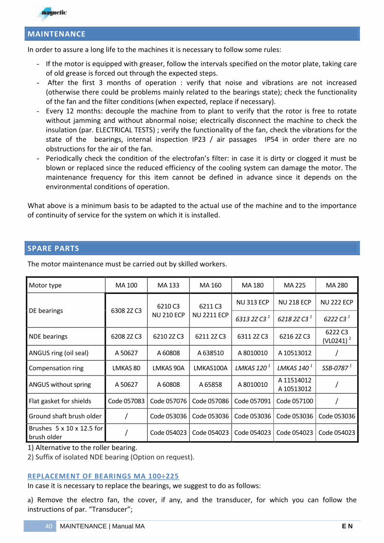
The motor maintenance must be carried out by skilled workers.
Motor type MA 100 MA 133 MA 160 MA 180 MA 225 MA 280
DE bearings 6308 2Z C3 6210 C3
NU 210 ECP 6211 C3
NU 2211 ECP
NU 313 ECP NU 218 ECP NU 222 ECP
6313 2Z C3 1 6218 2Z C3 1 6222 C3 1
NDE bearings 6208 2Z C3 6210 2Z C3 6211 2Z C3 6311 2Z C3 6216 2Z C3 6222 C3
(VL0241) 2
ANGUS ring (oil seal) A 50627 A 60808 A 638510 A 8010010 A 10513012 /
Compensation ring LMKAS 80 LMKAS 90A LMKAS100A LMKAS 120 1 LMKAS 140 1 SSB-0787 1
ANGUS without spring A 50627 A 60808 A 65858 A 8010010 A 11514012 A 10513012
/
Flat gasket for shields Code 057083 Code 057076 Code 057086 Code 057091 Code 057100 /
Ground shaft brush older / Code 053036 Code 053036 Code 053036 Code 053036 Code 053036
Brushes 5 x 10 x 12.5 for brush older
/ Code 054023 Code 054023 Code 054023 Code 054023 Code 054023
1) Alternative to the roller bearing. 2) Suffix of isolated NDE bearing (Option on request).
REPLACEMENT OF BEARINGS MA 100÷225 In case it is necessary to replace the bearings, we suggest to do as follows:
a) Remove the electro fan, the cover, if any, and the transducer, for which you can follow the instructions of par. “Transducer”;
E N Manual MA | SPARE PARTS 41
b) in order to easily reassemble it, mark the position of each part (by means of a colored pencil, or drawing pin) during the disassembly;
c) remove the clamping screws of the bearing clamping flange which are placed on the front on the driving end shield and then the shield clamping screws from the body, then remove the shields carefully;
d) remove the bearings by using a special extractor and carefully clean the machined parts of the shaft (remove old grease);
e) for motor with a driving end ball bearing, heat the bearing in an oil bath at 80-100°C, assemble it on the shaft by putting it against the shoulder of the axis until it cools off and then check that it is firmly secured on the shaft;
f) in the MA 133-160 (driving end) there are two bearings, first insert the ball bearing as shown in point [e] and then the roller bearing;
g) for the roller bearing, heat the inside ring of the bearing as shown in point [e] and then assemble it on the shaft by putting it against the ball bearing; once it is cooled off, assemble the outside part of bearing.
h) grease the two sides of the bearing by using part (30%) of the grease quantity shown in the table(Initial grease qty.)
i) reassemble the motor by carrying out the reverse operations;
j) Put the rest of the grease quantity by using the special nipple (placed on the external top for MA225 IP54-MA160 IP54; on the external front near shaft end for MA133 IP54; inside under the top cover for MA180 IP54/23 MA133-160 IP23).
REPLACEMENT OF BEARINGS MA 280 In case it is necessary to replace the bearings, we suggest to do as follows:
a) Remove the electrofan, the cover, if any, and the transducer for which you can follow the instructions of par. “Transducer”;
b) in order to easily reassemble it, mark the position of each part (by means of a colored pencil, drawing pin etc.) during the disassembly;
c) remove first the fixing screws [1] of bearing blocking flange [5] and then the fixing front flange [11] flange-screws [2];
d) remove the flange [11], unscrew the two grains [10] that block the ring [9] on the shaft and remove it carefully;
2
2
2 1
1
1
11 9 8 7 5
10

42 SPARE PARTS | Manual MA E N
e) remove the component [8] and, if present, the Seeger ring [7];
f) remove the shield fixing screws from the stator, remove carefully the shields;
g) remove the bearings by using a special extractor and carefully clean the machined parts of the shaft (remove old grease);
h) for motor with a driving end ball bearing, heat the bearing in an oil bath at 80-100°C, assemble it on the shaft by putting it against the shoulder of the axis until it cools off and then check that it is firmly secured on the shaft;
i) for the roller bearing operate as indicated at pos [h] by fitting the internal ring on the shaft by putting it against the axis shoulder until it cools off and then check that it is firmly secured on the shaft.
j) grease the two sides of the bearing by using art (30%) of the grease quantity shown in the table (Initial grease qty.)
k) reassemble the motor by carrying out the reverse operations;
l) with the motor running at low speed complete the greasing up to the foreseen quantity by using the special greaser (located above in the flange [11] on driving end and at the sides of the non-driving end shield).
BEARINGS MAINTENANCE TABLE After the replacement of the bearings, it is necessary to grease the new bearings (only those not shielded) with the INITIAL quantity of grease shown in the following table using the special "nipples" mentioned in the following chapters. During the periodic maintenance, follow the intervals specified in the motor plate, taking care to escape the grease / waste oil through the grease drain holes. All drain holes are closed through appropriate set screw, so we recommend, while greasing the motor, to remove the set screw in order to release the grease / oil. After that, make the motor turns for a few minutes and then close the drain through the appropriate set screw. In the motors with exhaust grease drain located under the door, we recommend to remove any grease / oil deposited inside the shield during the drainage phase.
In case the motor plate or is missing or not easily accessible, you can refer to the below table for the greasing of the motor during periodic maintenance (the time interval is calculated according to the maximum nominal speed, for lower speed the interval time is longer).
Motor Nominal
speed [RPM]
DE bearing 2 Type of grease
Time lag [h]
Grease quantity
[ gr ]
Initial grease quantity
[gr]
MA 133 3000 NU 210 ECP
SKF LGHP 2
4000 18 27 6210 C3
MA 160 2600 NU 2211 ECP
4500 23 37 6211 C3
MA 180 2500 NU 313 ECP 5200 23 70
MA 225 2500 NU 218 ECP 2800 24 137
MA 280 1600 NU 222 ECP 2100 38 137
MA 280 1600 6222 C3 1 5100 38 140
1) Alternative to the roller bearing. 2) Bearings for standard applications.
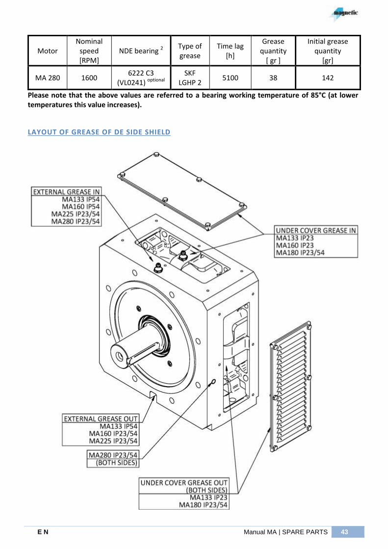
E N Manual MA | SPARE PARTS 43
Motor Nominal
speed [RPM]
NDE bearing 2 Type of grease
Time lag [h]
Grease quantity
[ gr ]
Initial grease quantity
[gr]
MA 280 1600 6222 C3
(VL0241) optional SKF
LGHP 2 5100 38 142
Please note that the above values are referred to a bearing working temperature of 85°C (at lower temperatures this value increases).
LAYOUT OF GREASE OF DE SIDE SHIELD
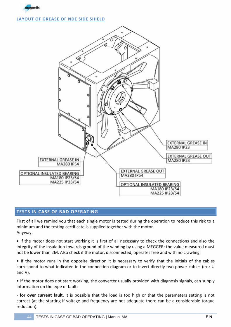
44 TESTS IN CASE OF BAD OPERATING | Manual MA E N
LAYOUT OF GREASE OF NDE SIDE SHIELD
TESTS IN CASE OF BAD OPERATING
First of all we remind you that each single motor is tested during the operation to reduce this risk to a minimum and the testing certificate is supplied together with the motor. Anyway:
• If the motor does not start working it is first of all necessary to check the connections and also the integrity of the insulation towards ground of the winding by using a MEGGER: the value measured must not be lower than 2M. Also check if the motor, disconnected, operates free and with no crawling.
• If the motor runs in the opposite direction it is necessary to verify that the initials of the cables correspond to what indicated in the connection diagram or to invert directly two power cables (ex.: U and V).
• If the motor does not start working, the converter usually provided with diagnosis signals, can supply information on the type of fault:
- for over current fault, it is possible that the load is too high or that the parameters setting is not correct (at the starting if voltage and frequency are not adequate there can be a considerable torque reduction).
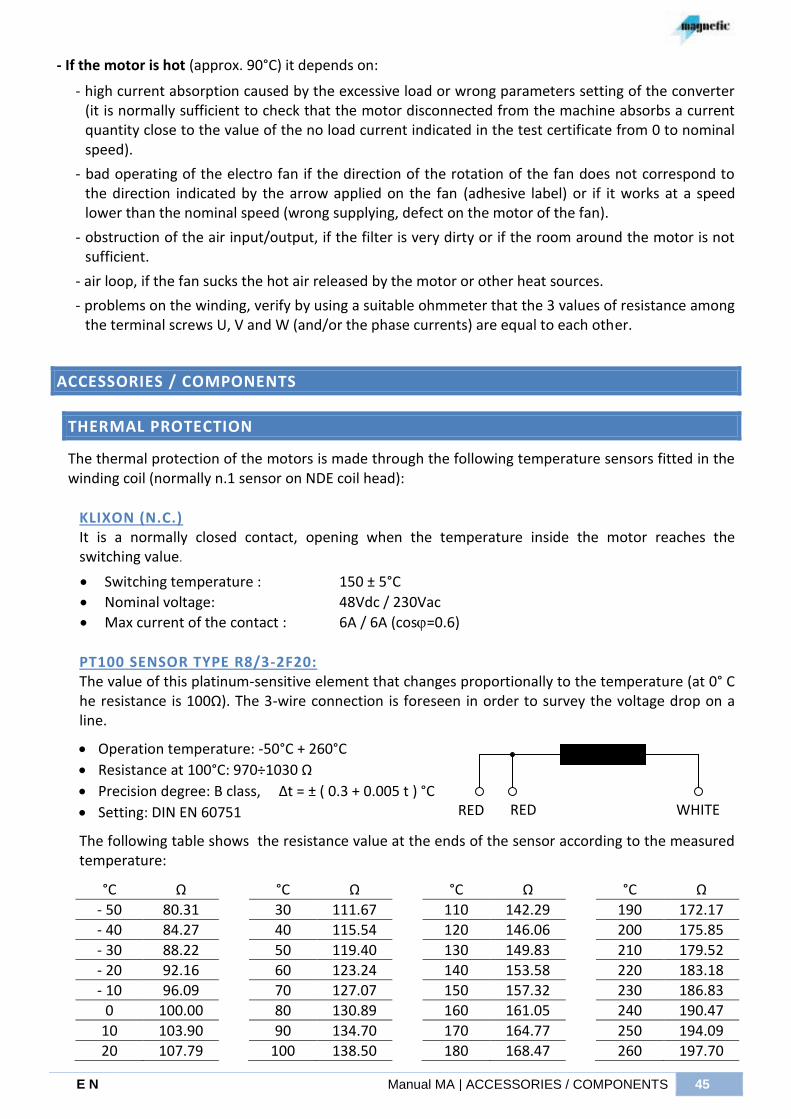
E N Manual MA | ACCESSORIES / COMPONENTS 45
- If the motor is hot (approx. 90°C) it depends on:
- high current absorption caused by the excessive load or wrong parameters setting of the converter (it is normally sufficient to check that the motor disconnected from the machine absorbs a current quantity close to the value of the no load current indicated in the test certificate from 0 to nominal speed).
- bad operating of the electro fan if the direction of the rotation of the fan does not correspond to the direction indicated by the arrow applied on the fan (adhesive label) or if it works at a speed lower than the nominal speed (wrong supplying, defect on the motor of the fan).
- obstruction of the air input/output, if the filter is very dirty or if the room around the motor is not sufficient.
- air loop, if the fan sucks the hot air released by the motor or other heat sources.
- problems on the winding, verify by using a suitable ohmmeter that the 3 values of resistance among the terminal screws U, V and W (and/or the phase currents) are equal to each other.
ACCESSORIES / COMPONENTS
THERMAL PROTECTION
The thermal protection of the motors is made through the following temperature sensors fitted in the winding coil (normally n.1 sensor on NDE coil head):
KLIXON (N.C.) It is a normally closed contact, opening when the temperature inside the motor reaches the switching value.
Switching temperature : 150 ± 5°C
Nominal voltage: 48Vdc / 230Vac
Max current of the contact : 6A / 6A (cos=0.6)
PT100 SENSOR TYPE R8/3-2F20: The value of this platinum-sensitive element that changes proportionally to the temperature (at 0° C he resistance is 100Ω). The 3-wire connection is foreseen in order to survey the voltage drop on a line.
Operation temperature: -50°C + 260°C
Resistance at 100°C: 970÷1030 Ω
Precision degree: B class, Δt = ± ( 0.3 + 0.005 t ) °C
Setting: DIN EN 60751
The following table shows the resistance value at the ends of the sensor according to the measured temperature:
°C Ω °C Ω °C Ω °C Ω
- 50 80.31 30 111.67 110 142.29 190 172.17
- 40 84.27 40 115.54 120 146.06 200 175.85
- 30 88.22 50 119.40 130 149.83 210 179.52
- 20 92.16 60 123.24 140 153.58 220 183.18
- 10 96.09 70 127.07 150 157.32 230 186.83
0 100.00 80 130.89 160 161.05 240 190.47
10 103.90 90 134.70 170 164.77 250 194.09
20 107.79 100 138.50 180 168.47 260 197.70
RED RED WHITE

46 THERMAL PROTECTION | Manual MA E N
KTY84/130 SENSOR: The value of this resistance changes proportionally in accordance with the speed (at 0°C the resistance is 498Ω). At the temperature of 100°C a continuous current of 2mA is recommended.
Operation temperature: -40°C + 300°C
Resistance at 100°C: 970÷1030 Ω
Measurement current @ 25/300°C: 10/2 mA
The following table shows the resistance value at the ends of the sensor according to the measured temperature:
Temperature °C R min Ω R usual Ω R max Ω
0 474 498 522
10 514 538 563
20 555 581 607
30 599 626 652
40 645 672 700
50 694 722 750
60 744 773 801
70 797 826 855
80 852 882 912
90 910 940 970
100 970 1000 1030
110 1029 1062 1096
120 1089 1127 1164
130 1152 1194 1235
140 1216 1262 1309
150 1282 1334 1385
160 1350 1407 1463
PTC SENSOR TYPE SNM130ES520: It is a “positive” thermistor where the nominal resistance (from 20÷550 Ω) increases drastically ≥1330Ω when approaching the temperature of 130°C. A measurement voltage ≥2,5Vdc is recommended.
Nominal reaction temperature: 130 °C (TREF)
Range of operating voltage : 2,5 VDC - 30 VDC
Max. sensor voltage recommended: 2,5 VDC - 7,5 VDC
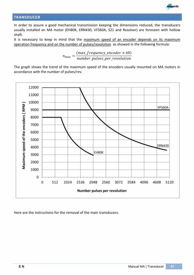
E N Manual MA | Transducer 47
TRANSDUCER
In order to assure a good mechanical transmission keeping the dimensions reduced, the transducers usually installed on MA motor (EH80K, ERN430, VFS60A, S21 and Resolver) are foreseen with hollow shaft. It is necessary to keep in mind that the maximum speed of an encoder depends on its maximum operation frequency and on the number of pulses/revolution as showed in the following formula:
( )
The graph shows the trend of the maximum speed of the encoders usually mounted on MA motors in accordance with the number of pulses/rev.
Here are the instructions for the removal of the main transducers.

48 TRANSDUCER | Manual MA E N
ENCODER ELTRA EH 80 K Characteristics:
Electronic output = Line Driver, Push Pull Resolution = from 200 to 2048 pulses/rev. Supply voltage = 5Vdc ± 10% or 8÷24Vdc ± 5% Max. current = 100mA + (15mA per channel) Max frequency = 100 kHz Mechanical max. speed = 8000 RPM
please see the motor plate data or the test certificate
To replace the encoder we suggest you to do what follows:
a) unscrew the encoder connector locking ferrule and push it towards the inside of the terminal box; b) remove carefully the silicone existing in the rubber gland fitted in the shield inside the terminal box; c) remove the gland pushing from the encoder side towards the outside of the terminal box; d) unscrew the plastic cap PG7 e) remove the screw M4 x 14; f) remove carefully the encoder (using the M5 threaded hole available after the remove of the screw).
To assembly the encoder do backwards what above restoring the silicone.
1
2
3 5
6
7
4
Spare parts table
000061139 - Anti-rotation pin
2 000084001 -3 Screws M5x20mm UNI5931
3 000056397 - Flange
4 000069055 - Shaft end
5 000047039 - V-Ring V-40A
6 000084069 - Screw M4x14mm UNI 5931
7 - Cap PG7
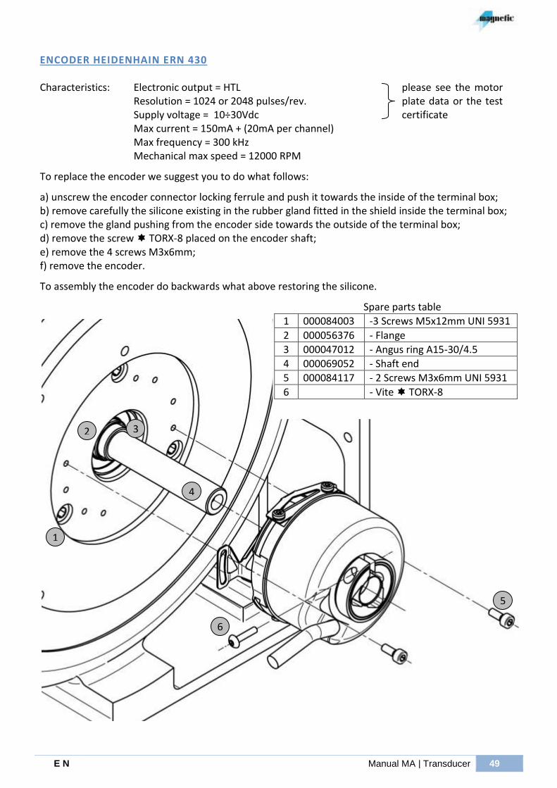
E N Manual MA | Transducer 49
ENCODER HEIDENHAIN ERN 430 Characteristics:
Electronic output = HTL
Resolution = 1024 or 2048 pulses/rev. Supply voltage = 10÷30Vdc Max current = 150mA + (20mA per channel) Max frequency = 300 kHz Mechanical max speed = 12000 RPM
please see the motor plate data or the test certificate
To replace the encoder we suggest you to do what follows:
a) unscrew the encoder connector locking ferrule and push it towards the inside of the terminal box; b) remove carefully the silicone existing in the rubber gland fitted in the shield inside the terminal box; c) remove the gland pushing from the encoder side towards the outside of the terminal box; d) remove the screw TORX-8 placed on the encoder shaft; e) remove the 4 screws M3x6mm; f) remove the encoder.
To assembly the encoder do backwards what above restoring the silicone.
1
2 3
5
4
6
Spare parts table
1 000084003 -3 Screws M5x12mm UNI 5931
2 000056376 - Flange
3 000047012 - Angus ring A15-30/4.5
4 000069052 - Shaft end
5 000084117 - 2 Screws M3x6mm UNI 5931
6 - Vite TORX-8

50 TRANSDUCER | Manual MA E N
ENCODER STEGMANN-SICK VFS 60 A (PROGRAMMABLE) Characteristics:
Electronic output = TTL, HTL
Resolution = from 1 to 65536 pulses/rev. Supply voltage = 5÷32Vdc Max current = 60mA + (40mA per channel) Max frequency = 820 kHz Mechanical max. speed = 9000 RPM
please see the motor plate data or the test certificate
To replace the encoder we suggest you to do what follows:
h) unscrew the screw “A” of the encoder cover and remove carefully the cable as showed in the picture i) loosen the screw TORX-10 placed on the encoder shaft; j) remove the screw M5x12mm; k) remove the encoder
It is normally not necessary to replace the encoder cable. If necessary please proceed as follows:
l) unscrew the encoder connector locking ferrule and push it towards the inside of the terminal box; m) remove carefully the silicone existing in the rubber gland fitted in the shield inside the terminal box; n) remove the gland pushing from the encoder side towards the outside of the terminal box
To assembly the encoder do backwards what above restoring the silicone.
1
2 3
5
4
6 7
A
Spare parts table
1 000084003 - 3 ScrewsM5x12mm UNI 5931
2 000056376 - Flange
3 000047012 - Angus ring A15-30/4.5
4 000069052 - Shaft end
5 000084117 - 2 Screws M3x6mm UNI 5931
6 - Screw TORX-10
7 - Insulating protection
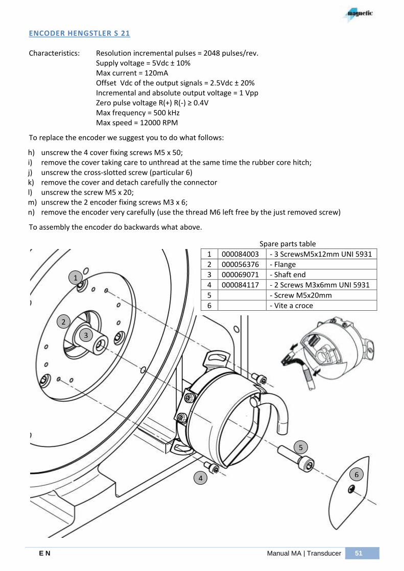
E N Manual MA | Transducer 51
ENCODER HENGSTLER S 21
Characteristics:
Resolution incremental pulses = 2048 pulses/rev. Supply voltage = 5Vdc ± 10% Max current = 120mA Offset Vdc of the output signals = 2.5Vdc ± 20% Incremental and absolute output voltage = 1 Vpp Zero pulse voltage R(+) R(-) ≥ 0.4V Max frequency = 500 kHz Max speed = 12000 RPM
To replace the encoder we suggest you to do what follows:
h) unscrew the 4 cover fixing screws M5 x 50; i) remove the cover taking care to unthread at the same time the rubber core hitch; j) unscrew the cross-slotted screw (particular 6) k) remove the cover and detach carefully the connector l) unscrew the screw M5 x 20; m) unscrew the 2 encoder fixing screws M3 x 6; n) remove the encoder very carefully (use the thread M6 left free by the just removed screw)
To assembly the encoder do backwards what above.
Spare parts table
1 000084003 - 3 ScrewsM5x12mm UNI 5931
2 000056376 - Flange
3 000069071 - Shaft end
4 000084117 - 2 Screws M3x6mm UNI 5931
5 - Screw M5x20mm
6 - Vite a croce
1
2
6
3
4
5
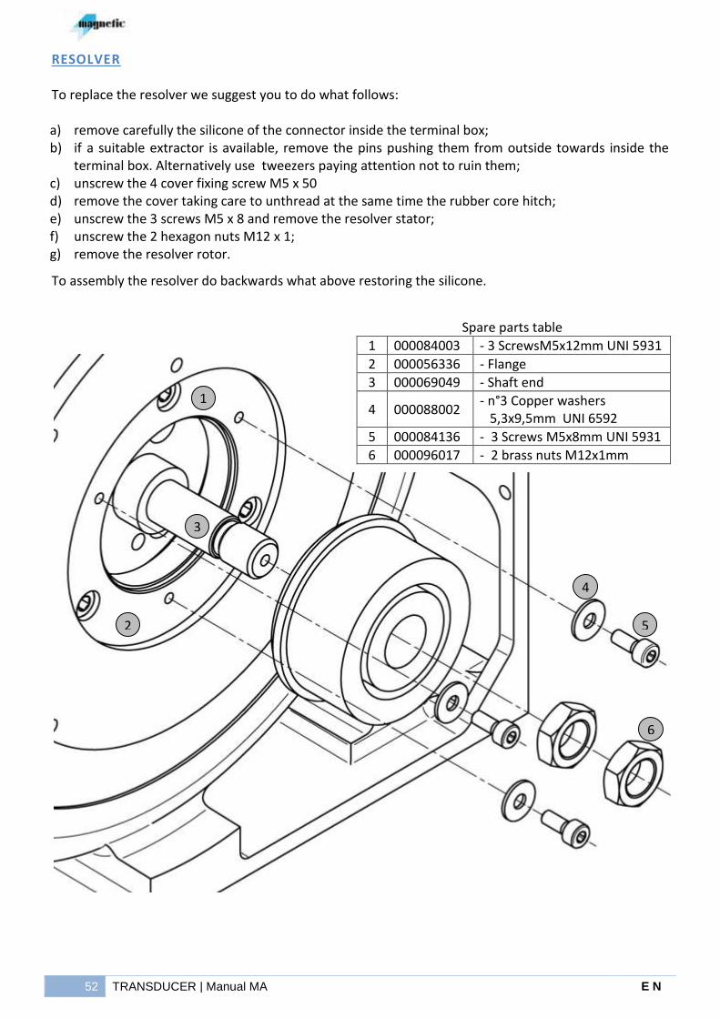
52 TRANSDUCER | Manual MA E N
RESOLVER To replace the resolver we suggest you to do what follows: a) remove carefully the silicone of the connector inside the terminal box; b) if a suitable extractor is available, remove the pins pushing them from outside towards inside the
terminal box. Alternatively use tweezers paying attention not to ruin them; c) unscrew the 4 cover fixing screw M5 x 50 d) remove the cover taking care to unthread at the same time the rubber core hitch; e) unscrew the 3 screws M5 x 8 and remove the resolver stator; f) unscrew the 2 hexagon nuts M12 x 1; g) remove the resolver rotor.
To assembly the resolver do backwards what above restoring the silicone.
Spare parts table
1 000084003 - 3 ScrewsM5x12mm UNI 5931
2 000056336 - Flange
3 000069049 - Shaft end
4 000088002 - n°3 Copper washers 5,3x9,5mm UNI 6592
5 000084136 - 3 Screws M5x8mm UNI 5931
6 000096017 - 2 brass nuts M12x1mm
1
2
6
3
4
5

E N Manual MA | Anemostatic relay 53
ANEMOSTATIC RELAY
The anemostatic relay, fixed to the fan casing near the motor, signals the electric fan stop or the complete closing of the suction inlet. So it shows the presence or absence of the air flow and not the degree of choking up of the filter. At the start of the electric fan, check that the contacts of this relay change their position from normally open to normally closed. The relay, as shown in the following figure, is composed by:
- common contact - normally closed contact (N.C. contact) - normally open contact (N.O. contact) - screw for the regulation of the intervention
threshold
(1) (2) (3) (4)
Contact: Nominal voltage : Max current of the contact:
30 ÷ 240Vac
5A (cos = 1)
0.5A (cos = 0.6)
In the case for some anomalies due to the transport of the motor or to a long storage period, the relay does not function, here we expose the setting procedure normally made on these relays in Magnetic testing room and also easy practicable from maintenance or mounting-staff in the place where the motor operates. First check that the copper adapter which intercepts the air flow inside of the electric fan casing, is in the correct direction of the air flow. Then through a tester, placed with one terminal on the common contact, make sure that the switching (change of the resistance value from 0 to infinite or vice versa) is correct in the two following conditions:
a) transition from off to on-position of the electric fan motor Attention: power supply voltage and frequency of the electric fan motor must be those of normal operation.
b) transition of the electric fan motor from normally turned on condition to suction inlet completely closed.
If at the above mentioned conditions there is an effective change of the contact, the relay setting is correct; otherwise it is necessary to turn the screw N°4 until a) and b) conditions happen.
N.O.

54 CONNECTIONS DIAGRAM FOR ‘MA’ MOTORS | Manual MA E N
CONNECTIONS DIAGRAM FOR ‘MA’ MOTORS
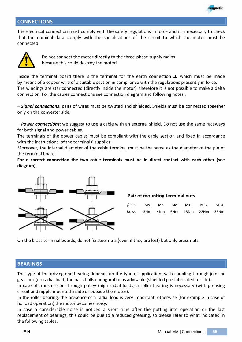
E N Manual MA | Connections 55
CONNECTIONS
The electrical connection must comply with the safety regulations in force and it is necessary to check that the nominal data comply with the specifications of the circuit to which the motor must be connected.
Do not connect the motor directly to the three-phase supply mains because this could destroy the motor!
Inside the terminal board there is the terminal for the earth connection which must be made by means of a copper wire of a suitable section in compliance with the regulations presently in force. The windings are star connected (directly inside the motor), therefore it is not possible to make a delta connection. For the cables connections see connection diagram and following notes : − Signal connections: pairs of wires must be twisted and shielded. Shields must be connected together only on the converter side. − Power connections: we suggest to use a cable with an external shield. Do not use the same raceways for both signal and power cables. The terminals of the power cables must be compliant with the cable section and fixed in accordance with the instructions of the terminals’ supplier. Moreover, the internal diameter of the cable terminal must be the same as the diameter of the pin of the terminal board. For a correct connection the two cable terminals must be in direct contact with each other (see diagram).
Pair of mounting terminal nuts
On the brass terminal boards, do not fix steel nuts (even if they are lost) but only brass nuts.
BEARINGS
The type of the driving end bearing depends on the type of application: with coupling through joint or gear box (no radial load) the balls-balls configuration is advisable (shielded pre-lubricated for life). In case of transmission through pulley (high radial loads) a roller bearing is necessary (with greasing circuit and nipple mounted inside or outside the motor). In the roller bearing, the presence of a radial load is very important, otherwise (for example in case of no load operation) the motor becomes noisy. In case a considerable noise is noticed a short time after the putting into operation or the last replacement of bearings, this could be due to a reduced greasing, so please refer to what indicated in the following tables.
Ø pin M5 M6 M8 M10 M12 M14
Brass 3Nm 4Nm 6Nm 13Nm 22Nm 35Nm
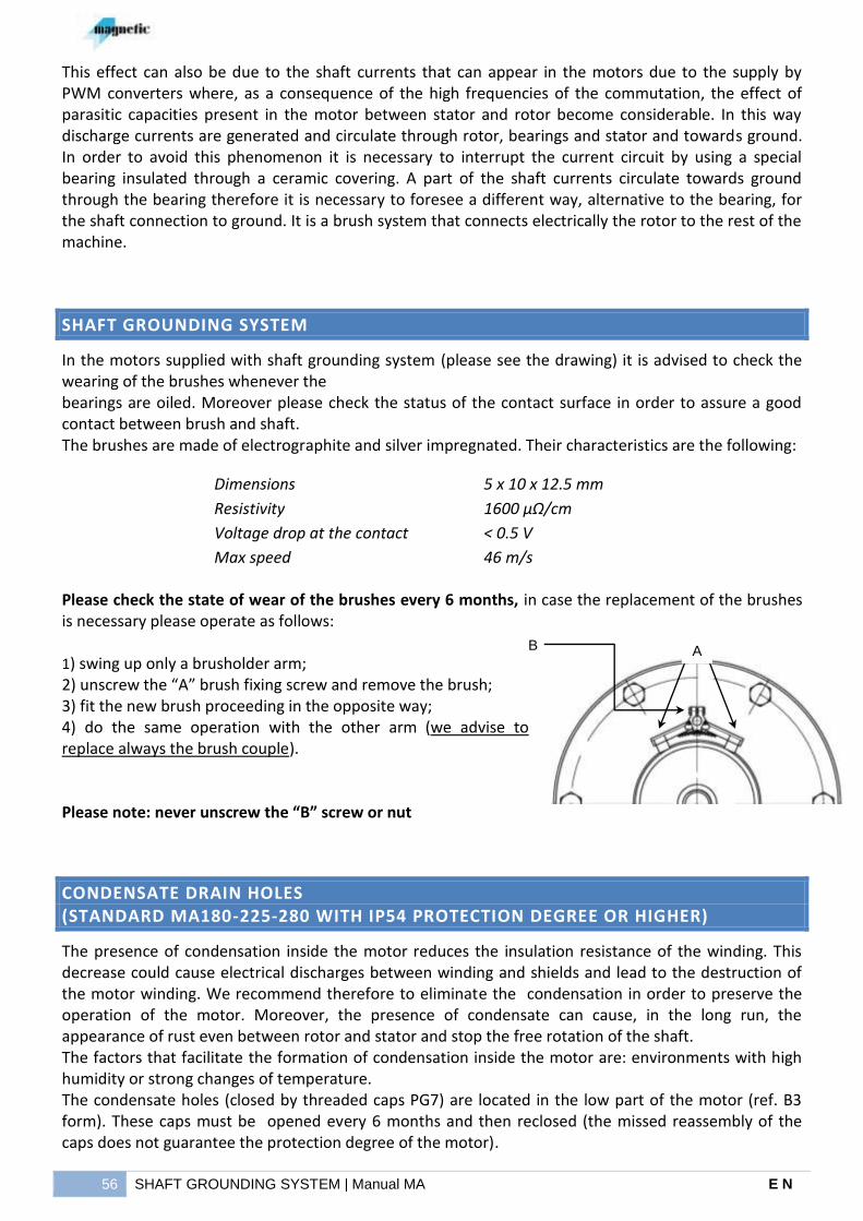
56 SHAFT GROUNDING SYSTEM | Manual MA E N
This effect can also be due to the shaft currents that can appear in the motors due to the supply by PWM converters where, as a consequence of the high frequencies of the commutation, the effect of parasitic capacities present in the motor between stator and rotor become considerable. In this way discharge currents are generated and circulate through rotor, bearings and stator and towards ground. In order to avoid this phenomenon it is necessary to interrupt the current circuit by using a special bearing insulated through a ceramic covering. A part of the shaft currents circulate towards ground through the bearing therefore it is necessary to foresee a different way, alternative to the bearing, for the shaft connection to ground. It is a brush system that connects electrically the rotor to the rest of the machine.
SHAFT GROUNDING SYSTEM
In the motors supplied with shaft grounding system (please see the drawing) it is advised to check the wearing of the brushes whenever the bearings are oiled. Moreover please check the status of the contact surface in order to assure a good contact between brush and shaft. The brushes are made of electrographite and silver impregnated. Their characteristics are the following:
Dimensions 5 x 10 x 12.5 mm
Resistivity 1600 µΩ/cm
Voltage drop at the contact < 0.5 V
Max speed 46 m/s
Please check the state of wear of the brushes every 6 months, in case the replacement of the brushes is necessary please operate as follows: 1) swing up only a brusholder arm; 2) unscrew the “A” brush fixing screw and remove the brush; 3) fit the new brush proceeding in the opposite way; 4) do the same operation with the other arm (we advise to replace always the brush couple). Please note: never unscrew the “B” screw or nut
CONDENSATE DRAIN HOLES (STANDARD MA180-225-280 WITH IP54 PROTECTION DEGREE OR HIGHER)
The presence of condensation inside the motor reduces the insulation resistance of the winding. This decrease could cause electrical discharges between winding and shields and lead to the destruction of the motor winding. We recommend therefore to eliminate the condensation in order to preserve the operation of the motor. Moreover, the presence of condensate can cause, in the long run, the appearance of rust even between rotor and stator and stop the free rotation of the shaft. The factors that facilitate the formation of condensation inside the motor are: environments with high humidity or strong changes of temperature. The condensate holes (closed by threaded caps PG7) are located in the low part of the motor (ref. B3 form). These caps must be opened every 6 months and then reclosed (the missed reassembly of the caps does not guarantee the protection degree of the motor).
A B
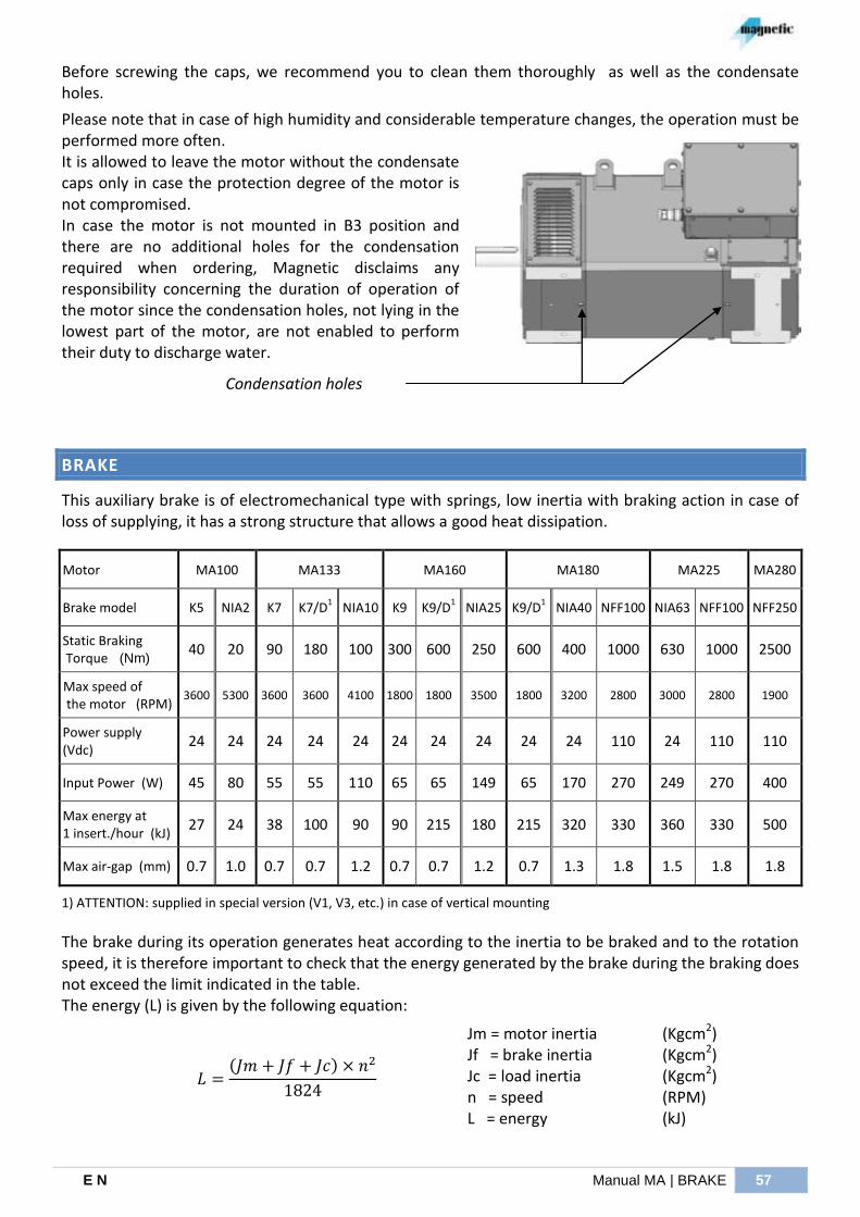
E N Manual MA | BRAKE 57
Before screwing the caps, we recommend you to clean them thoroughly as well as the condensate holes.
Please note that in case of high humidity and considerable temperature changes, the operation must be performed more often. It is allowed to leave the motor without the condensate caps only in case the protection degree of the motor is not compromised. In case the motor is not mounted in B3 position and there are no additional holes for the condensation required when ordering, Magnetic disclaims any responsibility concerning the duration of operation of the motor since the condensation holes, not lying in the lowest part of the motor, are not enabled to perform their duty to discharge water.
Condensation holes
BRAKE
This auxiliary brake is of electromechanical type with springs, low inertia with braking action in case of loss of supplying, it has a strong structure that allows a good heat dissipation.
Motor MA100 MA133 MA160 MA180 MA225 MA280
Brake model K5 NIA2 K7 K7/D1 NIA10 K9 K9/D
1 NIA25 K9/D
1 NIA40 NFF100 NIA63 NFF100 NFF250
Static Braking Torque (Nm)
40 20 90 180 100 300 600 250 600 400 1000 630 1000 2500
Max speed of the motor (RPM)
3600 5300 3600 3600 4100 1800 1800 3500 1800 3200 2800 3000 2800 1900
Power supply (Vdc)
24 24 24 24 24 24 24 24 24 24 110 24 110 110
Input Power (W) 45 80 55 55 110 65 65 149 65 170 270 249 270 400
Max energy at 1 insert./hour (kJ)
27 24 38 100 90 90 215 180 215 320 330 360 330 500
Max air-gap (mm) 0.7 1.0 0.7 0.7 1.2 0.7 0.7 1.2 0.7 1.3 1.8 1.5 1.8 1.8
1) ATTENTION: supplied in special version (V1, V3, etc.) in case of vertical mounting
The brake during its operation generates heat according to the inertia to be braked and to the rotation speed, it is therefore important to check that the energy generated by the brake during the braking does not exceed the limit indicated in the table. The energy (L) is given by the following equation:
( )
Jm = motor inertia Jf = brake inertia Jc = load inertia n = speed L = energy
(Kgcm2) (Kgcm2) (Kgcm2) (RPM) (kJ)
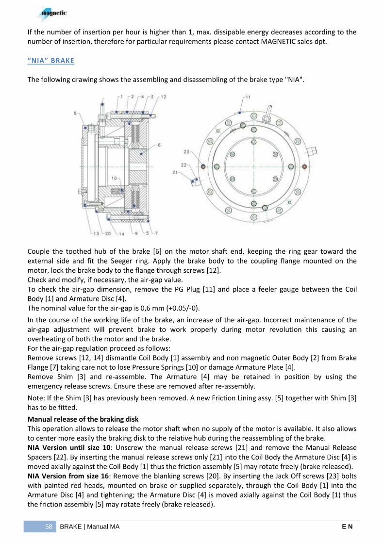
58 BRAKE | Manual MA E N
If the number of insertion per hour is higher than 1, max. dissipable energy decreases according to the number of insertion, therefore for particular requirements please contact MAGNETIC sales dpt.
“NIA” BRAKE
The following drawing shows the assembling and disassembling of the brake type "NIA".
Couple the toothed hub of the brake [6] on the motor shaft end, keeping the ring gear toward the external side and fit the Seeger ring. Apply the brake body to the coupling flange mounted on the motor, lock the brake body to the flange through screws [12]. Check and modify, if necessary, the air-gap value. To check the air-gap dimension, remove the PG Plug [11] and place a feeler gauge between the Coil Body [1] and Armature Disc [4]. The nominal value for the air-gap is 0,6 mm (+0.05/-0).
In the course of the working life of the brake, an increase of the air-gap. Incorrect maintenance of the air-gap adjustment will prevent brake to work properly during motor revolution this causing an overheating of both the motor and the brake. For the air-gap regulation proceed as follows: Remove screws [12, 14] dismantle Coil Body [1] assembly and non magnetic Outer Body [2] from Brake Flange [7] taking care not to lose Pressure Springs [10] or damage Armature Plate [4]. Remove Shim [3] and re-assemble. The Armature [4] may be retained in position by using the emergency release screws. Ensure these are removed after re-assembly.
Note: If the Shim [3] has previously been removed. A new Friction Lining assy. [5] together with Shim [3] has to be fitted.
Manual release of the braking disk This operation allows to release the motor shaft when no supply of the motor is available. It also allows to center more easily the braking disk to the relative hub during the reassembling of the brake. NIA Version until size 10: Unscrew the manual release screws [21] and remove the Manual Release Spacers [22]. By inserting the manual release screws only [21] into the Coil Body the Armature Disc [4] is moved axially against the Coil Body [1] thus the friction assembly [5] may rotate freely (brake released). NIA Version from size 16: Remove the blanking screws [20]. By inserting the Jack Off screws [23] bolts with painted red heads, mounted on brake or supplied separately, through the Coil Body [1] into the Armature Disc [4] and tightening; the Armature Disc [4] is moved axially against the Coil Body [1) thus the friction assembly [5] may rotate freely (brake released).
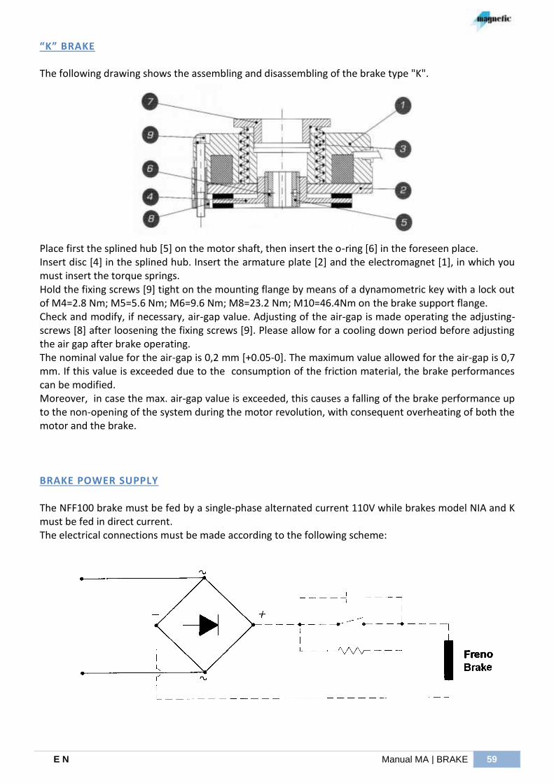
E N Manual MA | BRAKE 59
“K” BRAKE
The following drawing shows the assembling and disassembling of the brake type "K".
Place first the splined hub [5] on the motor shaft, then insert the o-ring [6] in the foreseen place. Insert disc [4] in the splined hub. Insert the armature plate [2] and the electromagnet [1], in which you must insert the torque springs. Hold the fixing screws [9] tight on the mounting flange by means of a dynamometric key with a lock out of M4=2.8 Nm; M5=5.6 Nm; M6=9.6 Nm; M8=23.2 Nm; M10=46.4Nm on the brake support flange. Check and modify, if necessary, air-gap value. Adjusting of the air-gap is made operating the adjusting-screws [8] after loosening the fixing screws [9]. Please allow for a cooling down period before adjusting the air gap after brake operating. The nominal value for the air-gap is 0,2 mm [+0.05-0]. The maximum value allowed for the air-gap is 0,7 mm. If this value is exceeded due to the consumption of the friction material, the brake performances can be modified. Moreover, in case the max. air-gap value is exceeded, this causes a falling of the brake performance up to the non-opening of the system during the motor revolution, with consequent overheating of both the motor and the brake.
BRAKE POWER SUPPLY The NFF100 brake must be fed by a single-phase alternated current 110V while brakes model NIA and K must be fed in direct current. The electrical connections must be made according to the following scheme:

I00251/G – 06/2014
MAGNETIC s.r.l. si riserva facoltà di modificare senza preavviso i dati contenuti nel presente manuale.
MAGNETIC s.r.l. reserves the right to change any data contained in this manual, without previous notice.
MAGNETIC s.r.l.
via del Lavoro, 7
I-36054 Montebello Vicentino (VI)
tel. +39 0444 649399
fax +39 0444 440495
www.magnetic.it