session five high integrity pressure protection systems...
TRANSCRIPT
Session Five: High integrity pressure protection systems (HIPPS): design, analysis, justification and implementation
Safety Control Systems Conference 2015 1
Session Five
High integrity pressure protection systems (HIPPS): design, analysis, justification and implementation
Luis M. Garcia G. CFSE, Charles Fialkowski CFSE, Vivek Sud and Christopher
Ng, PE Siemens Industry Inc.
Key Words Process Safety, LOPA, HIPS, SIL, API Standard 521, Availability, Reliability, Flare System, Safety Life Cycle concept.
Abstract HIPPS (High Integrity Pressure Protection Systems) are installed to provide overpressure protection for process equipment in the upstream and downstream process industries. To avert overpressure scenarios or minimize their associated consequences, HIPPS could be used to isolate, reduce, or divert sources of overpressure, thereby avoiding equipment damage and loss of containment.
In many cases the overpressure in a system is traditionally dealt with by a relief mechanism e.g. a flare or blow-down facility. The addition of a HIPPS system can help reduce the probability of excessive load on an existing pressure relief system and eliminate the high costs associated with purchasing new relief devices, resizing existing flare headers, re-rating flare knock out drums, redesigning the flare stack, etc. Also it provides the opportunity to minimize costs due to loss of operations.
A commonly used approach is to design HIPPS for flare load reduction as a Safety Integrity Level (SIL) 3 Safety Instrumented Function (SIF) or a SIL 2 SIF (depending on the company standard or practice). This work discusses how, instead of taking the customary “one size performance fits all” approach, the design could be based on the IEC 61511 Safety Lifecycle to determine the required risk reduction and select the appropriate SIL accordingly. This paper will discuss current practices; review benefits and drawbacks of SIL selection in these scenarios, and describe the impact on total cost of ownership.
Session Five: High integrity pressure protection systems (HIPPS): design, analysis, justification and implementation
Safety Control Systems Conference 2015 2
Table of Contents
Key Words 01
Abstract 01
Introduction 03
What is A HIP – Does it protect or mitigate? 04
What is a FCC? – Justification 05
High Pressure Scenario in the Fractionator 07
Safety Life Cycle Approach 12
SIL Calculations 13
SIL Verification 17
Conclusion 18
References 20
Session Five: High integrity pressure protection systems (HIPPS): design, analysis, justification and implementation
Safety Control Systems Conference 2015 3
Introduction High Integrity Protection System (HIPS) is sometimes used interchangeably with either High Integrity Pressure Protection System (HIPS) or High Integrity Temperature Protection System. The naming convention depends on the application and functioning characteristics but typically uses certain key words, such as High Integrity and Protection, to characterize their design concept.
According to API Standard 521: “A High-Integrity Protection Systems (HIPS) typically involves an arrangement of instruments, final control elements (e.g. valves, switches, etc.), and logic solvers configured in a manner designed to avoid overpressure incidents by removing the source of overpressure or by reducing the probability of an overpressure contingency to such a low level that it is no longer considered to be a credible case”.
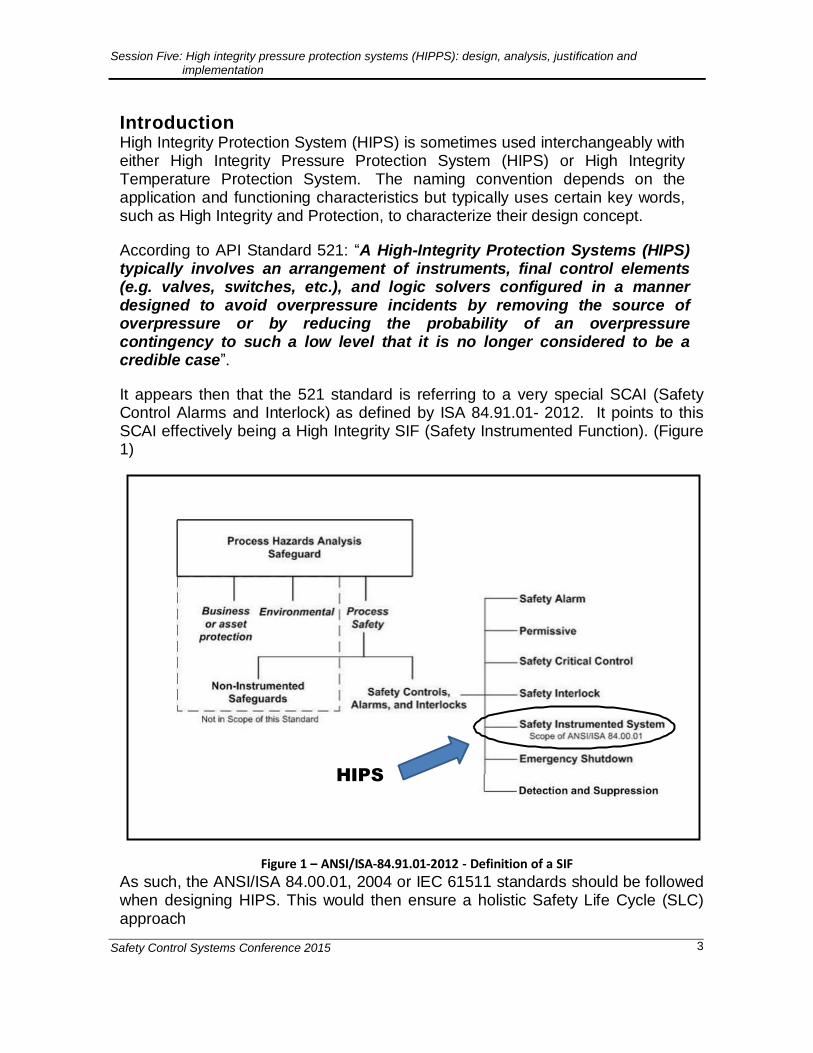
It appears then that the 521 standard is referring to a very special SCAI (Safety Control Alarms and Interlock) as defined by ISA 84.91.01- 2012. It points to this SCAI effectively being a High Integrity SIF (Safety Instrumented Function). (Figure 1)
HIPS
Figure 1 – ANSI/ISA-84.91.01-2012 - Definition of a SIF
As such, the ANSI/ISA 84.00.01, 2004 or IEC 61511 standards should be followed when designing HIPS. This would then ensure a holistic Safety Life Cycle (SLC) approach

Session Five: High integrity pressure protection systems (HIPPS): design, analysis, justification and implementation
Safety Control Systems Conference 2015 4
which would govern the methodology used to achieve and maintain the performance of the system from the cradle to the grave.
In API 521 Standard, clause 4.2.4 the second paragraph states: “The design shall comply with the local regulations and the owner’s risk tolerance criteria, whichever is more restrictive. … If these risk tolerance criteria are not available, then, as a minimum, the overall system performance including instrumented safeguards should provide safety-integrity-level 3 (SIL-3) performances”
The above statement could be misinterpreted by some to be a prescriptive approach to select SIL-3 without proper analysis and justification. Unnecessary burden may be imposed upon the SIF, thus making it impractical to achieve the intended risk reduction
After all that has been learned over the years, can anybody responsibly accept that “Risk tolerance criteria ARE NOT available”?
The reader may inadvertently conclude that:
- This is a guidance to make all HIPS SIL 3.
- This is a way to simplify up-front engineering efforts (just shifting focus or kicking the can down the road to the system designers)
This may be an expedient approach to specification, albeit a potentially costly one, but good practice dictates that the whole life cycle should be considered, and the implications of factors such as operations and maintenance should be taken into account. Note that : As a way to maintain high performance, test intervals are addressed by API Standard 521 (Annex E.5), as follows:
“… There are two other important aspects of testing that should be considered in setting testing intervals… The capability of the site at which the HIPS is to be installed to carry out such tests... There is little value in specifying a system that requires testing HIPS every three months where the site only has the resources for annual testing… Testing as a process contains the potential for introducing faults and spurious shutdowns due to human error. .. Thus, where possible, the aim should be to design a system that can achieve the desired availability with the minimum of off-line testing. The advent of supervised circuits, built-in diagnostics and the use of built-in redundancy (that facilitates on-line testing of components and circuits) all contribute to minimizing the frequency of off-line testing.”
However anyone who has done reliability studies on a SIF knows how hard it is to maintain a SIL 3 performance, even with Hardware Fault Tolerance of 2 using redundant arrangements of valves.
What is A HIPS – Does it protect or mitigate? The answer will depend on the scenario and the application being analyzed.
It might be an overpressure protection for individual equipment or systems (for example because of a blocked Outlet) or a mitigation system to limit the extent or
Session Five: High integrity pressure protection systems (HIPPS): design, analysis, justification and implementation
Safety Control Systems Conference 2015 5
magnitude of a release to a flare header (for example due to total power loss in a refinery where the flare system does not have the capacity to absorb the release from all units at the same time).
As a protection or mitigation system, there are many possible applications where the use of HIPS may be recommended; for example, in the case of a large liquid relief load due to overfilling of a feed surge drum or in the case of inadequate liquid disposal system (e.g. undersized flare KO drum). Another example is in case of loss of liquid level in an upstream high-pressure separator, resulting in gas blow-by to the low-pressure separator through the liquid level control valve. Another application is to avoid discharging hazardous material through atmospheric relief valves or vents on equipment and storage tanks, wherein fire/ explosion/ toxicity risk has been identified.
In this paper, we will discuss a reactor which is designed to generate a significant amount of vapor products, which in turn are sent to a distillation column or fractionator for product separation. The fractionator is designed for high operating temperature but low design pressure. For example, this could be the Main Fractionator column for a Fluidized Catalytic Cracking (FCC) unit, but the example could be applied to other processes and equipment with similar characteristics.
What is a FCC? - Justification A Fluid Catalytic Cracking Unit (FCCU) has been an integral part of oil refineries since 1942, when it was introduced in the United States by Exxon Corporation in response to a growing wartime need for hydrocarbon based fuels. An FCCU accepts chains of hydrocarbons and breaks them into smaller ones in a chemical process called cracking. This allows refineries to utilize their crude oil resources more efficiently, making more products such as gasoline for which there is a high demand.
Crude oil contains a wide variety of hydrocarbon chains of various lengths. Depending on the length of the hydrocarbon chain, it can be used in a variety of ways. For example, cooking gas usually has four carbon atoms, while gasoline for cars is a longer chain, containing eight carbon atoms. Lubricating oils are even longer, with 36 carbon atoms in the hydrocarbon chain. When oil is refined, these different hydrocarbon molecules are separated out for further use.
However, a barrel of crude oil will not always yield the desired ratio of hydrocarbons. For example, the market may be strong for gasoline, but weak for lubricating oil. Instead of discarding the lubricating oil, it is chemically cracked in an FCCU so that it can be turned into gasoline and other hydrocarbons with shorter chains. Hydrocarbons can be cracked in other ways, but chemical cracking in an FCCU is the most common and efficient
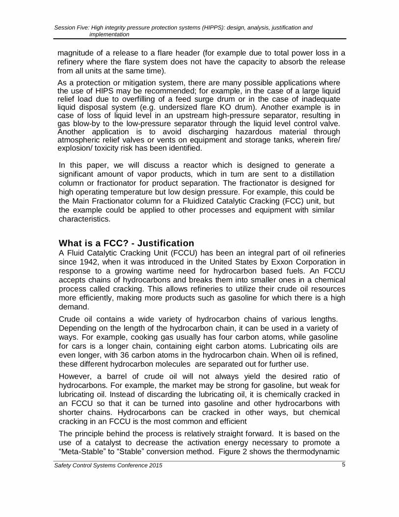
The principle behind the process is relatively straight forward. It is based on the use of a catalyst to decrease the activation energy necessary to promote a “Meta-Stable” to “Stable” conversion method. Figure 2 shows the thermodynamic
Session Five: High integrity pressure protection systems (HIPPS): design, analysis, justification and implementation
Safety Control Systems Conference 2015 6
fundamentals. The process is such that the Catalyst can be recovered in a cyclone tower and repeatedly recycled.
Figure 3 shows a simplified version of one of the many methodologies for this
process1:
1 The cracking reaction itself is endothermic, but there is a connected regeneration process for spent catalysts that is exothermic. The combined operation is exothermic
Session Five: High integrity pressure protection systems (HIPPS): design, analysis, justification and implementation
Safety Control Systems Conference 2015 7
ENER
GY
Pre-Heat Exchanger
Activation Energy
Energy Released
From Reactions
Raw Crude Oil
Meta-Stable
in Storage Tank
Product Vapor to
Fractionator
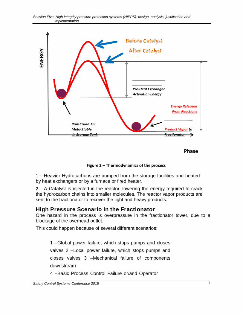
Figure 2 – Thermodynamics of the process
Phase
1 – Heavier Hydrocarbons are pumped from the storage facilities and heated by heat exchangers or by a furnace or fired heater.
2 – A Catalyst is injected in the reactor, lowering the energy required to crack the hydrocarbon chains into smaller molecules. The reactor vapor products are sent to the fractionator to recover the light and heavy products.
High Pressure Scenario in the Fractionator One hazard in the process is overpressure in the fractionator tower, due to a blockage of the overhead outlet.
This could happen because of several different scenarios:
1 –Global power failure, which stops pumps and closes
valves 2 –Local power failure, which stops pumps and
closes valves 3 –Mechanical failure of components
downstream
4 –Basic Process Control Failure or/and Operator
Session Five: High integrity pressure protection systems (HIPPS): design, analysis, justification and implementation
Safety Control Systems Conference 2015 8
error 5 –Loss of overhead cooling
6 –A combination of part or all of the above.
Session Five: High integrity pressure protection systems (HIPPS): design, analysis, justification and implementation
Safety Control Systems Conference 2015 9
Feed from Process or Storage Tank
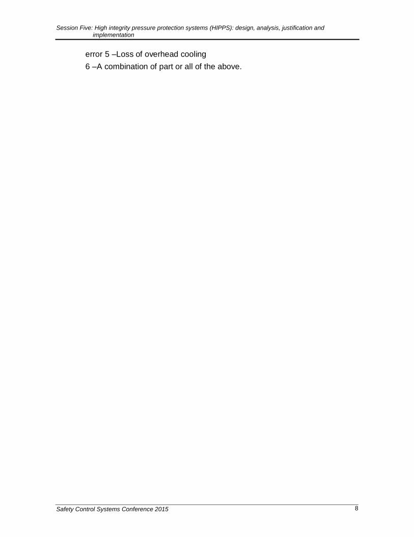
Normal Operation: 1. Charge Pump feeds the pre-heat train
2. Heat exchangers used to raise feed temperature
3. Combined Resulting Exothermic reaction generates vapor
in reactor
4. Fractionator overhead products sent to Gas Plant
Pre-Heat Exchangers
Charge Pumps
Control Valve
To Further
Processing
Fractionator
Reactor
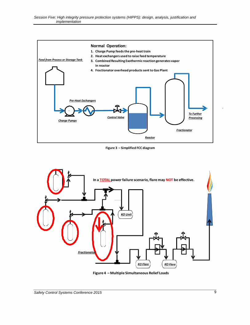
Figure 3 – Simplified FCC diagram
In a TOTAL power failure scenario, flare may NOT be effective.
KO Unit
Fractionator
KO Flare KO Flare
Figure 4 – Multiple Simultaneous Relief Loads
Session Five: High integrity pressure protection systems (HIPPS): design, analysis, justification and implementation
Safety Control Systems Conference 2015 10
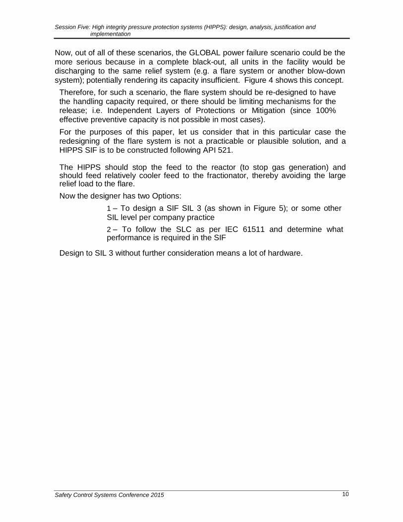
Now, out of all of these scenarios, the GLOBAL power failure scenario could be the more serious because in a complete black-out, all units in the facility would be discharging to the same relief system (e.g. a flare system or another blow-down system); potentially rendering its capacity insufficient. Figure 4 shows this concept.
Therefore, for such a scenario, the flare system should be re-designed to have the handling capacity required, or there should be limiting mechanisms for the release; i.e. Independent Layers of Protections or Mitigation (since 100% effective preventive capacity is not possible in most cases).
For the purposes of this paper, let us consider that in this particular case the redesigning of the flare system is not a practicable or plausible solution, and a HIPPS SIF is to be constructed following API 521.
The HIPPS should stop the feed to the reactor (to stop gas generation) and should feed relatively cooler feed to the fractionator, thereby avoiding the large relief load to the flare.
Now the designer has two Options:
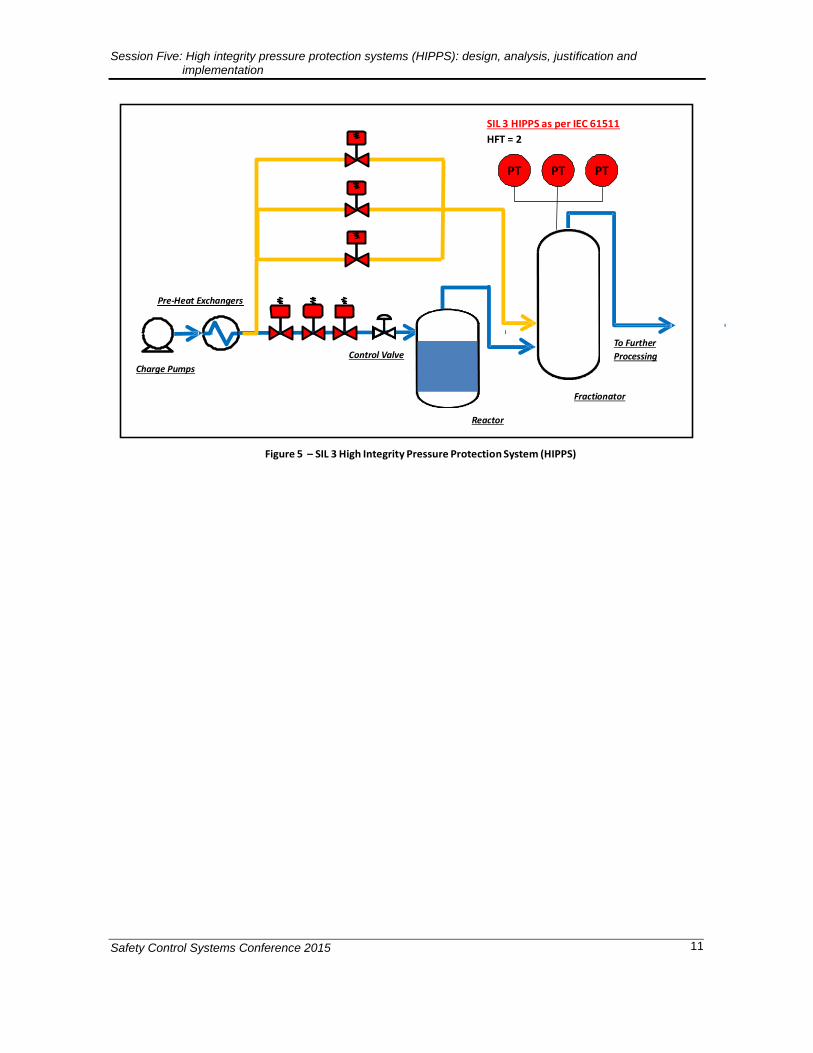
1 – To design a SIF SIL 3 (as shown in Figure 5); or some other SIL level per company practice
2 – To follow the SLC as per IEC 61511 and determine what performance is required in the SIF
Design to SIL 3 without further consideration means a lot of hardware.
Session Five: High integrity pressure protection systems (HIPPS): design, analysis, justification and implementation
Safety Control Systems Conference 2015 11
SIL 3 HIPPS as per IEC 61511
HFT = 2
PT PT PT
Pre-Heat Exchangers
Charge Pumps
Control Valve
To Further
Processing
Fractionator
Reactor
Figure 5 – SIL 3 High Integrity Pressure Protection System (HIPPS)
Session Five: High integrity pressure protection systems (HIPPS): design, analysis, justification and implementation
Safety Control Systems Conference 2015 12
This is because of the Hardware Fault Tolerance required by the IEC 61511
standards which is two (2) as; as it is indicated in Figure 5.2 Note: Proven In Use (PIU) or certified instrumentation (as per either route 1H or 2H IEC
61508) could and would reduce HFT by 1. Yet PIU is hard to achieve and two Systematic Capable SIL 2 instruments do not always reach SIL 3. Thus for this exercise we consider HFT = 2.
Therefore this approach of “one size fits all” is not only impracticable but difficult to maintain as well as a very imprecise way of assigning a SIF. How does one know that a Risk Reduction of 3 orders of magnitude is enough or too much?
A Safety Life Cycle approach is required, and for that, a Risk Criteria must be available.
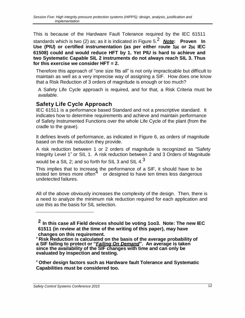
Safety Life Cycle Approach IEC 61511 is a performance based Standard and not a prescriptive standard. It indicates how to determine requirements and achieve and maintain performance of Safety Instrumented Functions over the whole Life Cycle of the plant (from the cradle to the grave). It defines levels of performance, as indicated in Figure 6, as orders of magnitude based on the risk reduction they provide.
A risk reduction between 1 or 2 orders of magnitude is recognized as “Safety Integrity Level 1” or SIL 1. A risk reduction between 2 and 3 Orders of Magnitude
would be a SIL 2; and so forth for SIL 3 and SIL 4.3
This implies that to increase the performance of a SIF, it should have to be tested ten times more often4 or designed to have ten times less dangerous undetected failures.
All of the above obviously increases the complexity of the design. Then, there is a need to analyze the minimum risk reduction required for each application and use this as the basis for SIL selection.
2 In this case all Field devices should be voting 1oo3. Note: The new IEC 61511 (in review at the time of the writing of this paper), may have changes on this requirement.
3 Risk Reduction is calculated on the basis of the average probability of a SIF failing to protect or “Failing On Demand”. An average is taken since the availability of the SIF changes with time and can only be evaluated by inspection and testing.
4 Other design factors such as Hardware fault Tolerance and Systematic Capabilities must be considered too.
Session Five: High integrity pressure protection systems (HIPPS): design, analysis, justification and implementation
Safety Control Systems Conference 2015 13
PFDave: 0.1 – 0.01
SIL 1
PFDave: 0.01 – 0.001
SIL 2
PFDave: 0.001 – 0.0001
SIL 3
PFDave: 0.0001 – 0.00001
SIL 4
IEC61508 “Demand Mode” PFDHIPS (ti)
SIL1 – RRF - PFDAVG
SIL2 – RRF - PFDAVG
Time between Inspections
Time
Figure 6 – Performance levels for SIF “on Demand “ Mode – Orders of Magnitude Concept
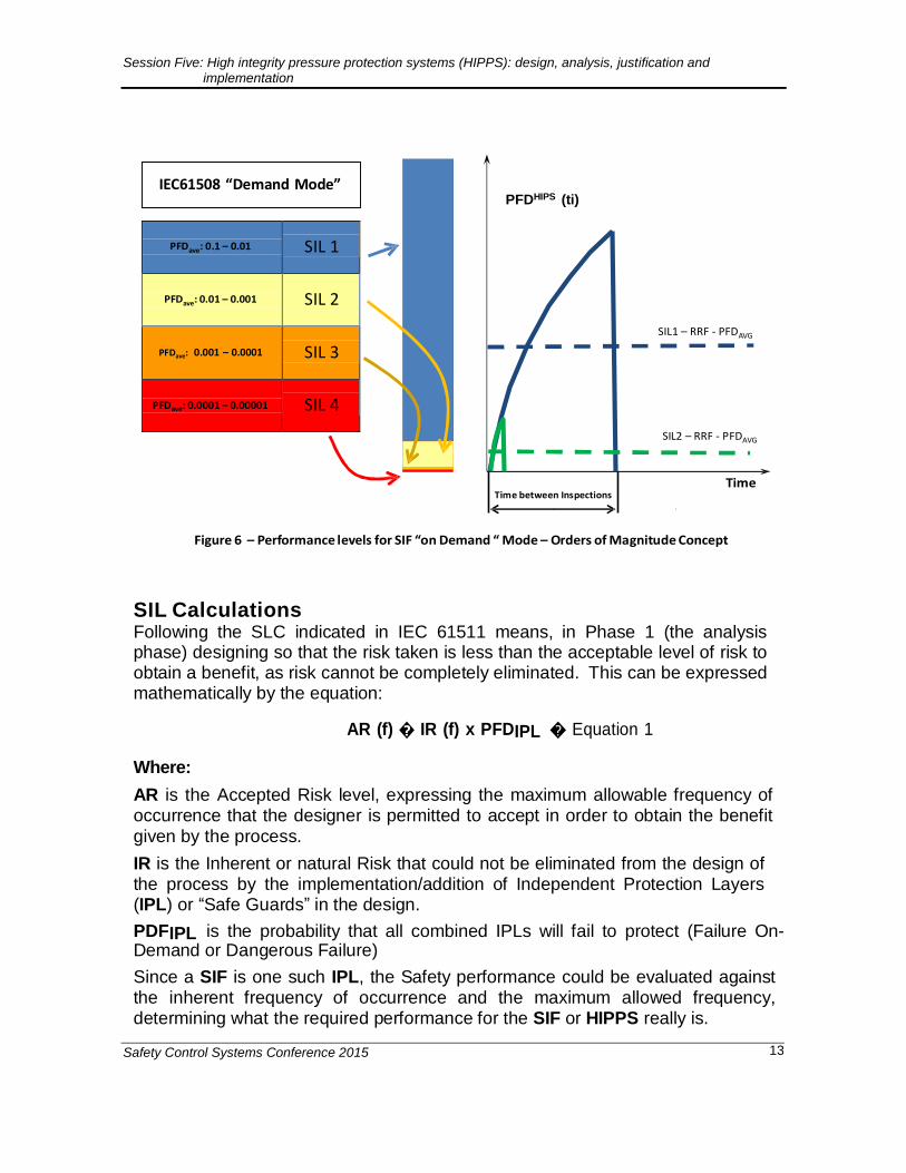
SIL Calculations Following the SLC indicated in IEC 61511 means, in Phase 1 (the analysis phase) designing so that the risk taken is less than the acceptable level of risk to obtain a benefit, as risk cannot be completely eliminated. This can be expressed mathematically by the equation:
AR (f) � IR (f) x PFDIPL � Equation 1
Where:
AR is the Accepted Risk level, expressing the maximum allowable frequency of occurrence that the designer is permitted to accept in order to obtain the benefit given by the process.
IR is the Inherent or natural Risk that could not be eliminated from the design of the process by the implementation/addition of Independent Protection Layers (IPL) or “Safe Guards” in the design.
PDFIPL is the probability that all combined IPLs will fail to protect (Failure On-Demand or Dangerous Failure)
Since a SIF is one such IPL, the Safety performance could be evaluated against the inherent frequency of occurrence and the maximum allowed frequency, determining what the required performance for the SIF or HIPPS really is.
Session Five: High integrity pressure protection systems (HIPPS): design, analysis, justification and implementation
Safety Control Systems Conference 2015 14
The above implies that the first tool we need is a clear risk tolerance criteria. In this case the designer has a Risk Matrix which is a semi-quantitative methodology to
determine acceptable levels of risk5
Session Five: High integrity pressure protection systems (HIPPS): design, analysis, justification and implementation
Safety Control Systems Conference 2015 15
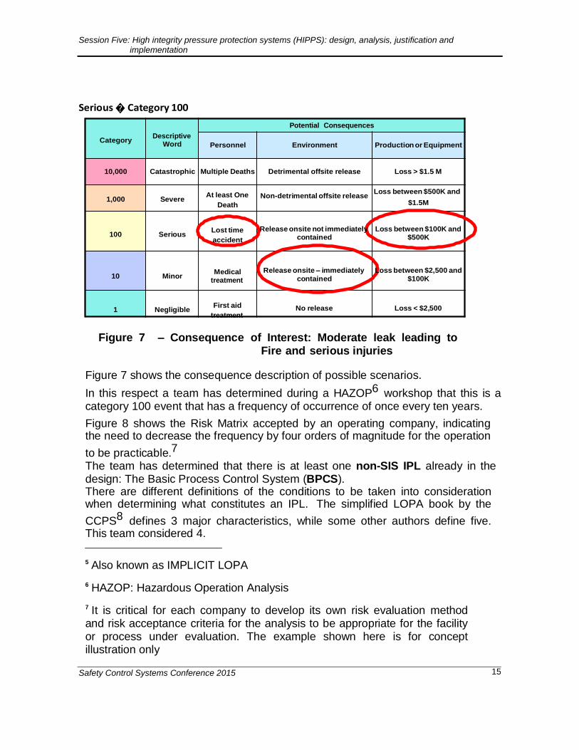
Serious � Category 100
Category Descriptive
Word
Potential Consequences
Personnel Environment Production or Equipment
10,000 Catastrophic Multiple Deaths Detrimental offsite release Loss > $1.5 M
1,000 Severe At least One
Death
Non-detrimental offsite release Loss between $500K and
$1.5M
100 Serious Lost time
accident
Release onsite not immediately contained
Loss between $100K and $500K
10 Minor Medical
treatment
Release onsite – immediately
contained
Loss between $2,500 and
$100K
1 Negligible First aid
treatment
No release Loss < $2,500
Figure 7 – Consequence of Interest: Moderate leak leading to Fire and serious injuries
Figure 7 shows the consequence description of possible scenarios.
In this respect a team has determined during a HAZOP6 workshop that this is a category 100 event that has a frequency of occurrence of once every ten years.
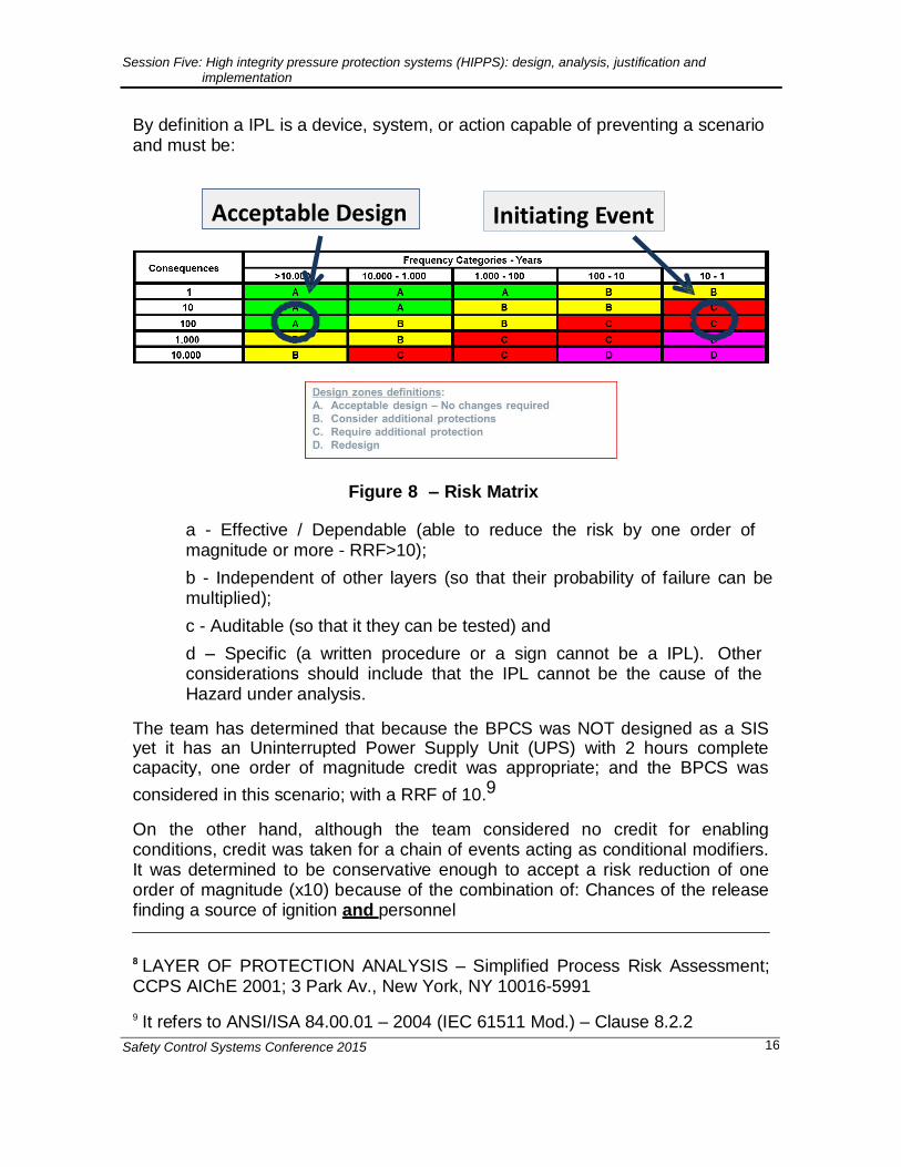
Figure 8 shows the Risk Matrix accepted by an operating company, indicating the need to decrease the frequency by four orders of magnitude for the operation
to be practicable.7 The team has determined that there is at least one non-SIS IPL already in the design: The Basic Process Control System (BPCS). There are different definitions of the conditions to be taken into consideration when determining what constitutes an IPL. The simplified LOPA book by the
CCPS8 defines 3 major characteristics, while some other authors define five. This team considered 4.
5 Also known as IMPLICIT LOPA
6 HAZOP: Hazardous Operation Analysis
7 It is critical for each company to develop its own risk evaluation method and risk acceptance criteria for the analysis to be appropriate for the facility or process under evaluation. The example shown here is for concept illustration only
Session Five: High integrity pressure protection systems (HIPPS): design, analysis, justification and implementation
Safety Control Systems Conference 2015 16
By definition a IPL is a device, system, or action capable of preventing a scenario and must be:
Acceptable Design Initiating Event
Figure 8 – Risk Matrix
a - Effective / Dependable (able to reduce the risk by one order of magnitude or more - RRF>10);
b - Independent of other layers (so that their probability of failure can be multiplied);
c - Auditable (so that it they can be tested) and
d – Specific (a written procedure or a sign cannot be a IPL). Other considerations should include that the IPL cannot be the cause of the Hazard under analysis.
The team has determined that because the BPCS was NOT designed as a SIS yet it has an Uninterrupted Power Supply Unit (UPS) with 2 hours complete capacity, one order of magnitude credit was appropriate; and the BPCS was
considered in this scenario; with a RRF of 10.9
On the other hand, although the team considered no credit for enabling conditions, credit was taken for a chain of events acting as conditional modifiers. It was determined to be conservative enough to accept a risk reduction of one order of magnitude (x10) because of the combination of: Chances of the release finding a source of ignition and personnel
8 LAYER OF PROTECTION ANALYSIS – Simplified Process Risk Assessment; CCPS AIChE 2001; 3 Park Av., New York, NY 10016-5991
9 It refers to ANSI/ISA 84.00.01 – 2004 (IEC 61511 Mod.) – Clause 8.2.2
Session Five: High integrity pressure protection systems (HIPPS): design, analysis, justification and implementation
Safety Control Systems Conference 2015 17
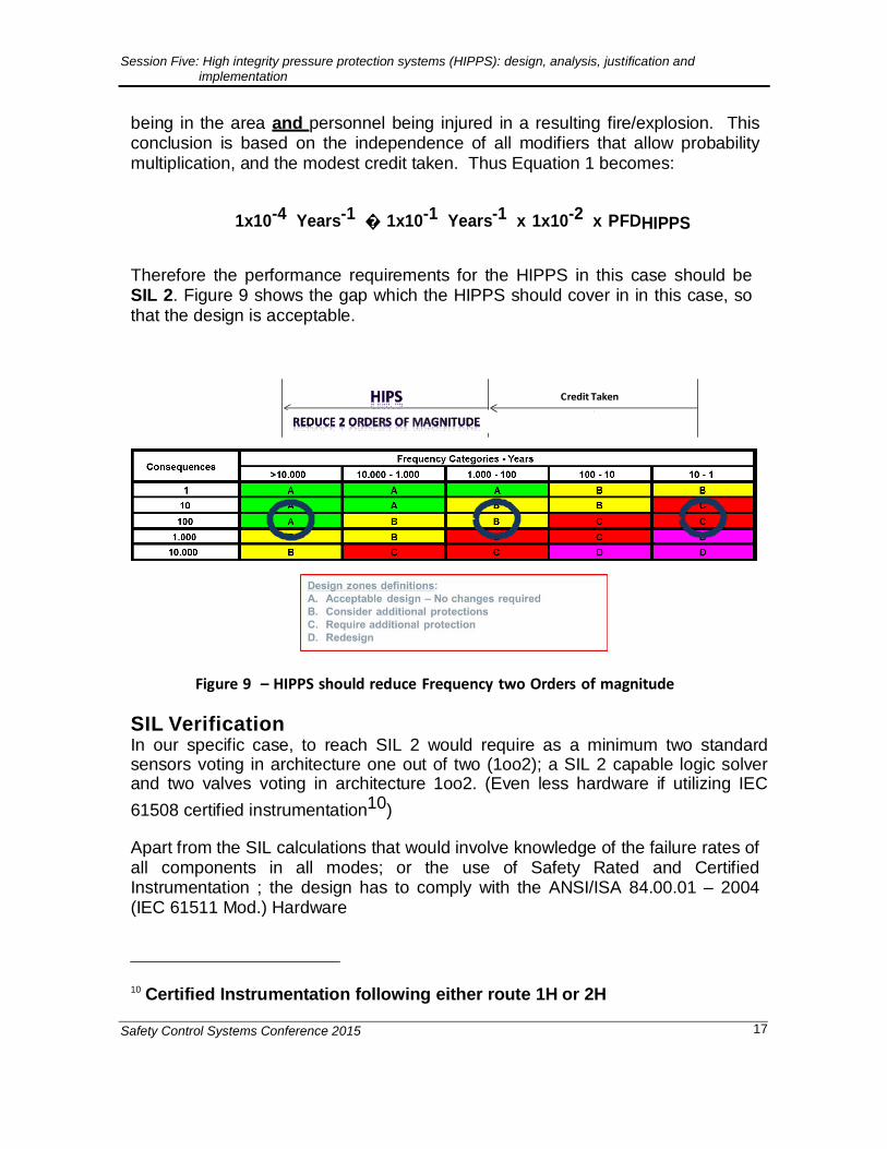
being in the area and personnel being injured in a resulting fire/explosion. This conclusion is based on the independence of all modifiers that allow probability multiplication, and the modest credit taken. Thus Equation 1 becomes:
1x10⁻⁴ Years-1 � 1x10⁻¹ Years-1 x 1x10-2 x PFDHIPPS
Therefore the performance requirements for the HIPPS in this case should be SIL 2. Figure 9 shows the gap which the HIPPS should cover in in this case, so that the design is acceptable.
Credit Taken
Figure 9 – HIPPS should reduce Frequency two Orders of magnitude
SIL Verification In our specific case, to reach SIL 2 would require as a minimum two standard sensors voting in architecture one out of two (1oo2); a SIL 2 capable logic solver and two valves voting in architecture 1oo2. (Even less hardware if utilizing IEC
61508 certified instrumentation10)
Apart from the SIL calculations that would involve knowledge of the failure rates of all components in all modes; or the use of Safety Rated and Certified Instrumentation ; the design has to comply with the ANSI/ISA 84.00.01 – 2004 (IEC 61511 Mod.) Hardware
10 Certified Instrumentation following either route 1H or 2H
Session Five: High integrity pressure protection systems (HIPPS): design, analysis, justification and implementation
Safety Control Systems Conference 2015 18
SIL Minimum Hardware Fault Tolerance 1 0 2 1 3 2 4 See IEC 61508
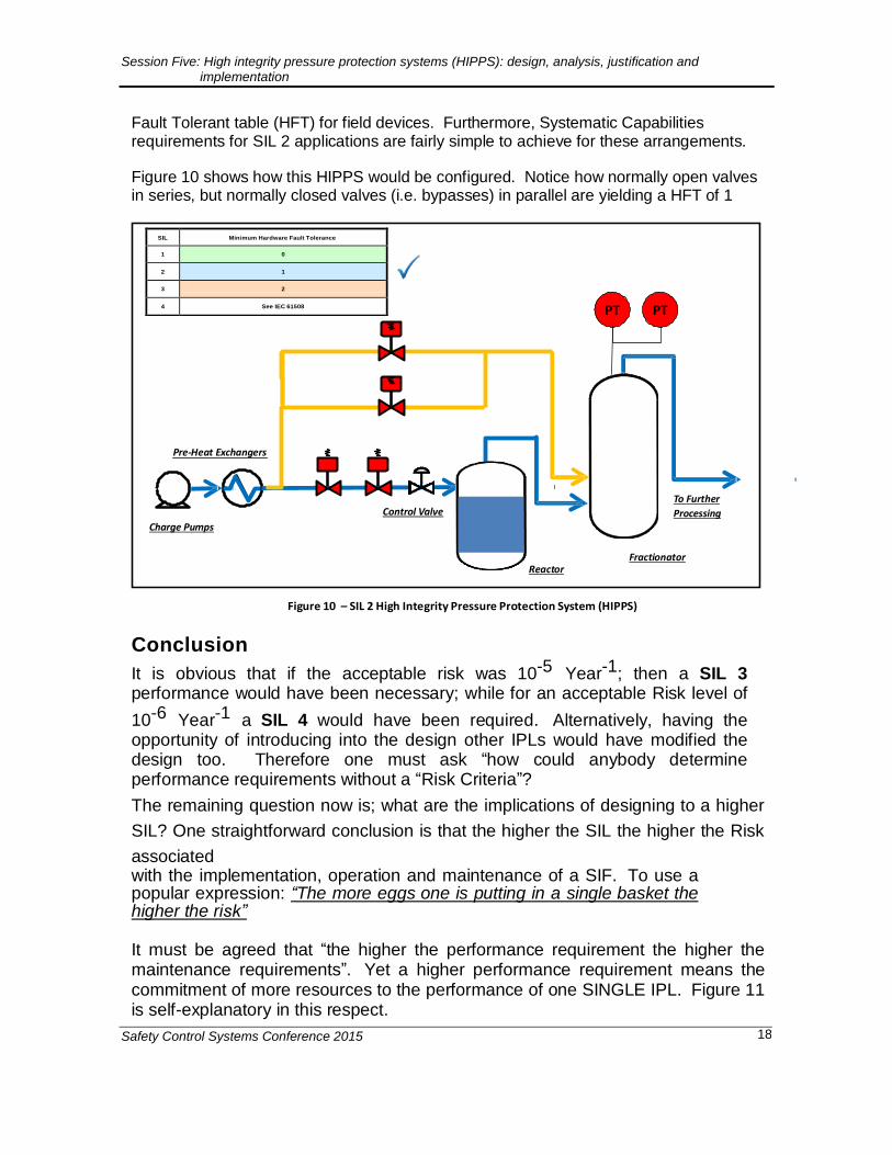
Fault Tolerant table (HFT) for field devices. Furthermore, Systematic Capabilities requirements for SIL 2 applications are fairly simple to achieve for these arrangements.
Figure 10 shows how this HIPPS would be configured. Notice how normally open valves in series, but normally closed valves (i.e. bypasses) in parallel are yielding a HFT of 1
PT PT
Pre-Heat Exchangers
Charge Pumps
Control Valve
To Further
Processing
Reactor
Fractionator
Figure 10 – SIL 2 High Integrity Pressure Protection System (HIPPS)
Conclusion
It is obvious that if the acceptable risk was 10-5 Year-1; then a SIL 3 performance would have been necessary; while for an acceptable Risk level of
10-6 Year-1 a SIL 4 would have been required. Alternatively, having the opportunity of introducing into the design other IPLs would have modified the design too. Therefore one must ask “how could anybody determine performance requirements without a “Risk Criteria”?
The remaining question now is; what are the implications of designing to a higher
SIL? One straightforward conclusion is that the higher the SIL the higher the Risk
associated with the implementation, operation and maintenance of a SIF. To use a popular expression: “The more eggs one is putting in a single basket the higher the risk”
It must be agreed that “the higher the performance requirement the higher the maintenance requirements”. Yet a higher performance requirement means the commitment of more resources to the performance of one SINGLE IPL. Figure 11 is self-explanatory in this respect.

Session Five: High integrity pressure protection systems (HIPPS): design, analysis, justification and implementation
Safety Control Systems Conference 2015 19
Increase SIL 2 to SIL 3
Equipment costs (need more)
Installation costs (mechanical, piping, wiring, etc.)
Physical space considerations (do you have available space to add taps,
piping, etc.?)
Maintenance (preventive maintenance, spare parts, proof
testing, etc.)
Operations (bypassing, spurious trip, complexity)
Figure 11 – Total Cost of Ownership considerations when increasing SIL
It is not only the increase in hardware requirements to comply with the Hardware Fault Tolerance Tables in IEC 61511; it is the maintenance of performance along the whole SLC of the SIF with includes addressing the increased complexity of the function.

Session Five: High integrity pressure protection systems (HIPPS): design, analysis, justification and implementation
Safety Control Systems Conference 2015 20
References
1. IEC 61508, Functional Safety of Electrical/Electronic/Programmable Safety- related Systems, Part 1-7, Geneva: International Electrotechnical Commission, 2010.
2. IEC 61511, Functional Safety: Safety Instrumented Systems for the Process
Industry Sector, Parts 1-3, Geneva: International Electrotechnical Commission, 2003.
3. ANSI/ISA S84.00.01-2004, Application of Safety Instrumented Systems for the
Process Industries, The International Society of Automation, Research Triangle Park, NC, 2004.
4. LAYER OF PROTECTION ANALYSIS – Simplified Process Risk Assessment;
CCPS AIChE 2001; 3 Park Av., New York, NY 10016-5991
5. Goble, W. M., Control Systems Safety Evaluation & Reliability, Research Triangle Park, NC - ISA 1998
6. API Standard 521, Pressure-relieving and Depressuring Systems, 6th edition,
January 2014.