high integrity pressure protection systems - fiorentini · pdf filehigh integrity pressure...
TRANSCRIPT

HIPPSHigh Integrity Pressure Protection Systems

High Integrity Pressure Protection Systems HIPPS
HIPPS is an acronym for High Integrity Pressure Protection System, which is a specific application of Safety Instrumented System (SIS) The function of a HIPPS is to protect downstream equipment against overpressure or upset conditions coming from the upstream.This is achieved by quickly closing two in-series dedicated safety shut-off valves to preventing further pressurisation of downstream piping. The entire HIPPS package mainly consists of:> Initiators> Logic Solver> Final Elements
It is designed in order to reach the desired fail-safe condition for the process according to the following standards:
> IEC 61508: ”Functional Safety of Electrical/Electronic/Programmable Electronic Safety Related System”
> IEC 61511: ”Functional Safety: safety instrumented systems for the process industry sector”> ANSI/ISA S84.01, ”Application of Safety Instrumented Systems for the Process Industries”
WHAT IS A HIPPS ?
Economic:HIPPS are used in Oil & Gas industry in order to provide pressure protection to pipelines, piping, vessels and process packages against over pressure, allowing the use of lower design pressure downstream the HIPPS SYSTEM.Lower allowable design pressure especially in pipeline and vessel applications has as its greatest advantages the reduction of the wall thickness and the effects related to it, and specifically:
• Weightandcostreductionforpipingandvesselsdownstream the HIPPS• Increasedcapacity/throughputinflowlineapplications• Transportationandstoragecostreductionduetovolumeandweightsreduction
Impossible without Hipps
Uneconomic without Hipps
DISTANCE
PR
ES
SU
RE
MAIN ADVANTAGES OF USING A HIPPS
Environmental:
The HIPPS SYSTEM highly reduces or eliminates the necessity to install relief devices such as relief valves, avoiding gas emissions into the atmosphere.
Safety:
The protection and reliability factor assured by a HIPPS totally prevents overpressure on every kind of downstream package.
HIPPS becomes the most feasible and practicable approach especially when:
• Environmental restrictions and safety constraints limit the venting• Overpressure risk shall be reduced• Extremelyhighpressureand/orflowrateareinvolved• Sizingofreliefdeviceisdifficulttodefineorinadequateduetochemicalreactions,multiphasefluidsor
pluggingonexistingsystemsinordertoavoidreplacementofflaresystemwhenaddingnewunits.
The SIS standards are performance-based with the safety integrity level (SIL) as the primary performance measurement. The SIL must be assigned by the user based on the risk reduction necessary to achieve the user’s risk tolerance. It is the user’s responsibility to ensure consistent and appropriate SIL assignments by establishing a risk management philosophy and risk tolerance. The risk reduction provided by the HIPPS is equivalent to the probability of failure on demand attributable to all of the HIPPS devices from the sensor through the logic solver and final elements.
WHEN TO USE A HIPPS ?
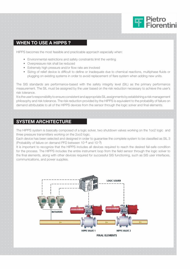
The HIPPS system is basically composed of a logic solver, two shutdown valves working on the 1oo2 logic and three pressure transmitters working on the 2oo3 logic.Each device has been selected and designed in order to guarantee the complete system to be classified as SIL 3 (Probability of failure on demand PFD between 10-4 and 10-3)It is important to recognize that the HIPPS includes all devices required to reach the desired fail-safe condition for the process. The HIPPS includes the entire instrument loop from the field sensor through the logic solver to the final elements, along with other devices required for successful SIS functioning, such as SIS user interfaces, communications, and power supplies.
SYSTEM ARCHITECTURE

High Integrity Pressure Protection Systems HIPPS
The logic solver is responsible for activation of the relevant signal outputs on the basis of the preconfigured applications and inputs from the initiators.PLC available on the market, SIL 3 certified, are used as logic solver. The system consist of a Central Processing Unit (CPU) and fail-safe redundant I/O suitable for safety-related applications.All safety communication between the control unit and the associated I/O cards are redundant.The logic solver can also be designed based on Solid State Logic (SSL), as alternative.Control Cabinet can be supplied suitable for hazardous area installation in EEx-d enclosure IP-66 or for safe area installation in standard 19” rack cabinet IP-54.
The final elements contribute with approximately 50% to the PFD of the complete system; our HIPPS system is based on n°2 in series final elements working on a logic 1oo2.
Pietro Fiorentini, thanks to its long documented experience in design and manufacture different type of valves since 1940, is able to provide a wide range of final elements of DELTAFLUX SERIES for HIPPS applications, SIL 3 CERTIFIED (according to IEC 61508).The overall response time of the system can be in the range of 2 or 3 seconds.Valve can be supplied with different construction material for all its components (body, bonnet, seat, ball, steam). Valve size ranges from 2” to 36” rating up to ANSI 1500.
The pressure sensing initiators are electronic pressure transmitters, two wire 4-20 mA smart devices, “mounted on an Interlock Manifold” and wired to separate card in the logic solver. The 2oo3 voting logic is implemented in the logic solver. The pressure transmitter contains self diagnostic and is programmed to send its output to a specified failure state.
INITIATORS
LOGIC SOLVER
FINAL ELEMENTS
PIETRO FIORENTINI has the capability to design, manufacture, assemble, test and provide all the required certificates.THE HIPPS System is based on a logic solver with two shutdown valves and three pressure transmitters.

HIPPS WITH DELTAFLUX SERIES ADVANTAGES
DeltafluxforHIPPSapplicationisaquarterturnvalvedesignedtobeopenedagainstfulldifferentialpressure;thereis no need to install a by-pass line for pressurization and start-up as typically needed with standard ball valves. This significantly reduces engineering, capital and installation costs. The hazard caused by accidentally leaving the by-pass open is also avoided.IEC standards, in order to reach top safety levels, recommend to avoid the by-pass on final elements.
NO BYPASS:
Moreover, one of the most difficult accomplishment of complying with SIS standards is the testing interval often required for final elements such as block valves.Most SIS block valves are function tested only at unit turnaround, consequently many users are looking for ways to supplement the off-line full stroke test, such as on-line full stroke testing or partial stroke testing.WithDELTAFLUX it iseasier toperformPartialStrokeTesting (PST),acosteffectivealternative toon-lineFullStroke Testing (FST).The valve is designed to maintain tight shut-off capabilities under all possible operating conditions and even long periodsofinactivitydonotinfluenceitsresponsetime.
t
Partial stroke proof testingTI = 1 month
PST=1 monthFST= 3 years
PFD (t)
PFDagv
PFDagv(PST)
Residual Risk
Full stroke1 year
Extended Full stroke test 3 years
For example:Extending the full stroke testing to 3 years at
turnaround, and implementing partial stroke
testing every 3 months, the PFDavg is still lower
than the original PFDavg at FST of 1 year without
PST.
PARTIAL STROKE:

High Integrity Pressure Protection Systems HIPPS
IEC 61508:Is a performance based standard which provides a detailed framework and life-cycle approach for the design and implementation of safety systems with different level of risk definition. This standard is mainly focused on Electrical/Electronic/Programmable Electronic Safety related equipment, but it also provides a framework for safety related equipments, including mechanical components.SIS:The “performance” of the safety instrumented system (SIS) is based on a target safety integrity level (SIL) that is defined during the safety requirements specification development.According to the standards the ability of the SIS to achieve a specific SIL must be validated at each stage of design and prior to any change made to the design after commissioning. The entire operation, testing, and maintenance procedures and practices are also judged for agreement with the target SIL.SIL:Four different SIL are defined, depending the consequences severity, possibility of avoiding hazardous events and likelihood frequencies of the event. The SIL must be assigned by the user based on the risk reduction necessary to achieve the user’s risk tolerance. It is user’s responsibility to ensure consistent and appropriate SIL assignments by establishing a risk management philosophy and risk tolerance.The risk reduction provided by the HIPPS is equivalent to the probability of failure on demand attributable (PFD) to all of the HIPPS devices from the sensor through the logic solver and final elements. Relationship between SIL and PFD for low Demand Mode of Operation is shown in following Table.
STANDARDS
TABLE
According to IEC 61508/11 in order to meet the SIL 3 requirements, the system must comply with both probabilistic requirements and with architectural constraints.Pietro Fiorentini can provide The PDF report or 3rd party SIL certificate.
CERTIFICATION
Safety IntegrityLevel (SIL)
Low Demand Mode of Operation Average Probability of Failure on Demand (PFD)
Risk Reduction Factor (RRF)
4 ≥ 10-5 to < 10-4 10,000 to 100,000
3 ≥ 10-4 to < 10-3 1,000 to 10,000
2 ≥ 10-3 to < 10-2 100 to 1,000
1 ≥ 10-2 to < 10-1 10 to 100
According to IEC 61508 in order to meet the SIL 3 requirements, the system must comply with both probabilistic requirements and with architectural constraints.

OPERATION & MAINTENANCE HIPPS
The HIPPS must be operated, maintained and tested throughout the life of the plant. The high integrity of HIPPS is often achieved through the use of frequent testing. Once the required testing interval is determined for a particular HIPPS design, the testing must be performed at that frequency. It can be six months or one year.Pietro Fiorentini thanks to his SERVICE DIVISION is able to operate on site testing and to provide the necessary documentation in order to preserve the SIL level of the whole system.

Pietro Fiorentini S.p.A.via E.Fermi 8/10I-36057 Arcugnano (VI) Italy
Tel. +39 0444 968.511Fax. +39 0444 960.468
Thedataarenotbinding.Wereservetheright to make eventual changes without prior notice.
www.fiorentini.com
Gas treatment plants On site serviceReducing & metering station
Plants & Packages
CT-s 224-E February 10