high integrity pressure protection system (hipps)ctq.com.mx/resources/hipps-en.pdf · high...
TRANSCRIPT

High Integrity PressureProtection System (HIPPS)
What is a HIPPS?
HIPPS, High Integrity PressureProtection System
What is the solution for increasing environmental awareness?
What is the over-pressurization of a plant?
What's the difference with the traditional relief system?
Too much pressure on the lines can cause explosions, hazards, toxic chemicals that will be released into the atmosphere -threatening lives and endangering the environment.
In many cases, the need for pressure relief, including torch burning, that damages the environment is also eliminated or reduced.
HIPPS are installed
instead of conventional mechanical relief valves to handle high flow rates and high pressures, reducing the risk of production units exceeding their design pressure.
It is a system of relief of high pressure and flow, which lead dangerous processes to a safe predictable state within a certain safe time.
Where can use HIPPS?
They are used in the oil and gas industryas well as in liquefied natural gas (LNG)facilities and transport and storagesystems to ensure the safety ofpipelines, ships and process packages.Some examples of the application ofHIPPS in the Oil & Gas industry arementioned below:
• Long-distance connection of a high-pressure marginal reservoir with existingsurface facilities.
• High pressure well connected to a lowpressure flow line.
• Protection of flexible risers against highpressures (Floating Structures)
Applications:
• Wellhead flowline• Pipeline and compressor stations• Flaring systems• Separation and Processing
Facilities• Gas plants• Gas storage• Floating production storage and
offloading (FPSO) vessels• Offshore platforms• Onshore operations

HIPPS´ Technical
Specifications
REDUNDANCY:₋ 2003 Pressure Transmitters₋ Isolators to DCS (tripping and deflection alarms)₋ 2003 Relays₋ 1002 Locking valves with 2oo2D-SOV
TESTS:₋ Transmitters and relays arround 5 years₋ 1 Solenoid for 1 month and partial stroke test₋ 5 year complete test
PERFORMANCE:₋ SIL 3₋ > 200 travel spurious trips

₋ Severe Operating Conditions₋ Safety Critical Operations₋ Reliability in remote locations
"All these factors are key concerns for theoil and gas equipment used in upstream,intermediate and downstream processes.Control valves are a crucial necessity forabsolute closure and reliable pressure andflow control”.
SIMPLE OR DOUBLE VALVE, MOUNTED ON SKID OR INDEPENDENT, PNEUMATIC, HYDRAULIC OR LINE GAS.
HIPPS
A HIPPS is designed and built in accordance with IEC 61508 and IEC 61511 standards. These international standards refer to Safety functions and instrumented
safety systems.
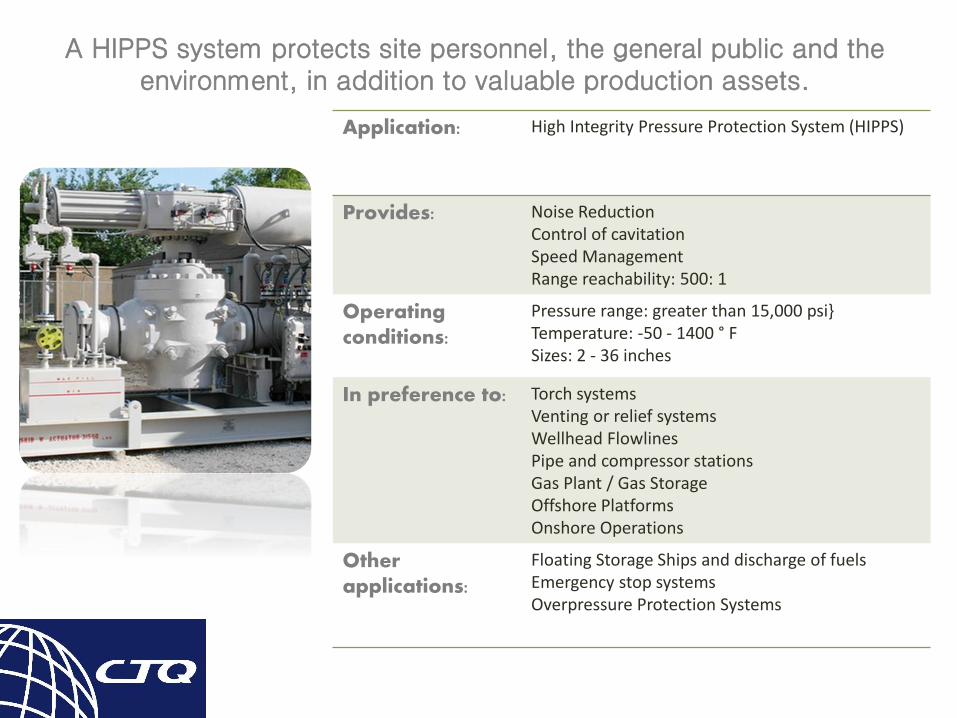
Application: High Integrity Pressure Protection System (HIPPS)
Provides: Noise ReductionControl of cavitationSpeed ManagementRange reachability: 500: 1
Operatingconditions:
Pressure range: greater than 15,000 psi}Temperature: -50 - 1400 ° FSizes: 2 - 36 inches
In preference to: Torch systemsVenting or relief systemsWellhead FlowlinesPipe and compressor stationsGas Plant / Gas StorageOffshore PlatformsOnshore Operations
Other applications:
Floating Storage Ships and discharge of fuelsEmergency stop systemsOverpressure Protection Systems
A HIPPS system protects site personnel, the general public and the environment, in addition to valuable production assets.
HIPPS´ Justification
& Benefits
JUSTIFICATION
Mechanical relief devices are available to improve concerning:
Environmental considerations Safety, identifying and mitigating the overpressure risk Economic Justifications, Project costs reduction (The undesirable safety relief valves, burners,
downstream piping) Reduction or elimination of the flare (little or no hydrocarbon in the flame) Remove safety valves (API 521, ASME Code Case 2211, ANSI / ISA 84.01-2004, IEC 61511) Need to operate a more practical system, Platform weight saving (no flare, no safety relief
valve stem, downstream pipe reduction, compact package), Space saving. Increased flexibility, Increase operating pressure, performance and production Increased diagnostics and reduced downtime (fault location, reset and continuous production) Reduce false trips
BENEFITS
Less gas burning, means money in the pocket Less gas burning, means happy atmosphere Liberate valuable real estate

Standards
BACKGROUND:
Until August 1996, ASME required the installation of pressure relief devices In Code Case 2211, ASME recognized that overpressure protection should be provided by the
most appropriate engineering option The use of HIPPS can be used but should result in an installation that is equally safe or safer
than the conventional design The proposed HIPPS is independent of the possible causes of overpressure; It is as reliable as
the pressure relief device it is replacing; And is able to fully mitigate an overpressure event.
International standards to allow the application of highly reliable instrumented safety systems (SIS) to replace traditional mechanical relief devices are:
API 521 Code Case 2211 of ASME Section VIII, Division 1 and 2 ANSI / ISA 84.01-2004 IEC 61511
Directrices de HIPPS
IEC 61508 defines specific guidelines for developing the SIS for risk reduction
IEC 61511 defines the applications of the process sector that provides guidance for the implementation of the SIS in the process industries
These documents govern the development of a HIPPS (like specialized SIS) in applications for the protection of pressure of overpressure
These international standards govern the HIPPS design and define the level of safety integrity (SIL) required for the HIPPS
For the application of HIPPS:
The application of these new standards and the later development of the SIS technology have allowed the application to replace the mechanical devices:
The reduction of risks required, results from the need to have SIS security systems with high availability and reliability
These systems are often called High Integrity Pressure Protection Systems (HIPPS).

Example of Risk Matrix
Matriz de Asignación de SIL para Determinar el nivel de SIL que se asignara
Higher 2 2 2 3 NS NS
-4
Meaningful 1 1 2 2 3 NS
-3
ModerateNR 1 1 2 2 3
-2
Lesser NR NR NR 1 1 2
-1
L M H (2) (3) (4)
(1) Remote Occasional Probable Frequent
NS = Not suitable; It's required additional safeties
NR = Not required; SIF most likely it doesn´t necessary
S
E
V
E
R
I
T
Y
FRECUENCY
SIS standards cover a variety of techniques for determining SIL requirements; Risk Matrix, RiskGraph and LOPA (protection analysis layers) are techniques that are considered to determine thelevel of risk for protection by the SIS system.
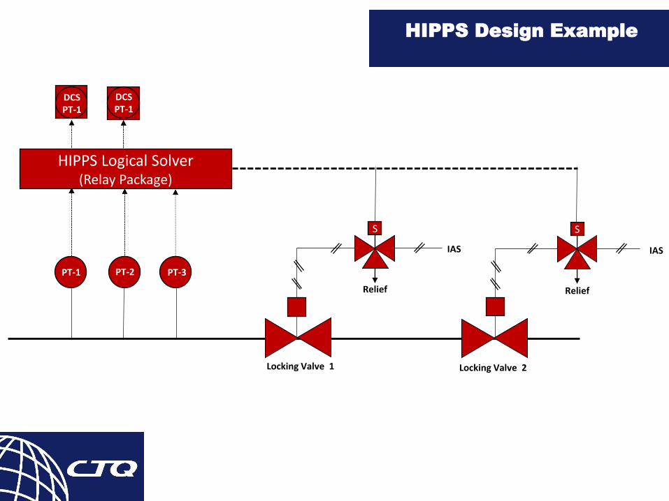
HIPPS Design Example
HIPPS Logical Solver(Relay Package)
S S
DCSPT-1
DCSPT-1
PT-1 PT-2 PT-3
Relief
IAS
Relief
IAS
Locking Valve 1 Locking Valve 2
The IEC 61508 standard refers mainly to the LOGIC SOLUTIONS
Less attention to components
61508 defines the System as a logical solver, the initiators and the final elements.
Reliable valves are required
Controls
Actuators
HPU
The System Approach
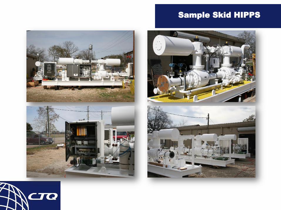
Sample Skid HIPPS

Sample Skid HIPPS
Logic Solver
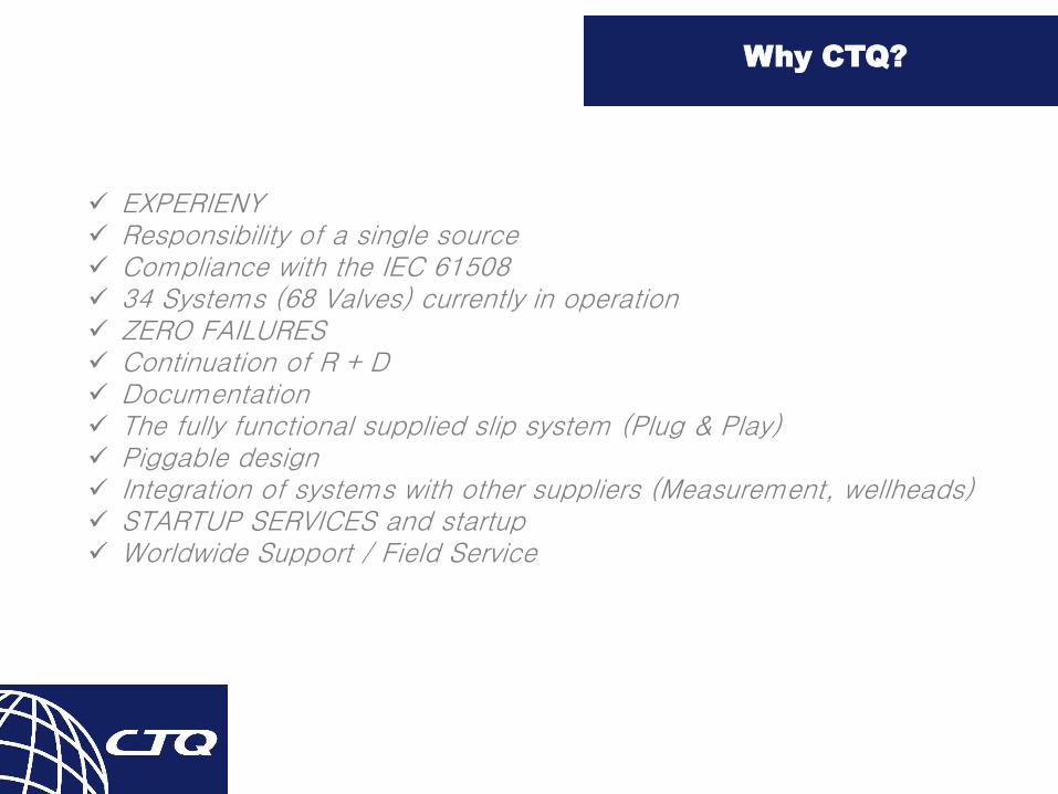
Why CTQ?
EXPERIENY Responsibility of a single source Compliance with the IEC 61508 34 Systems (68 Valves) currently in operation ZERO FAILURES Continuation of R + D Documentation The fully functional supplied slip system (Plug & Play) Piggable design Integration of systems with other suppliers (Measurement, wellheads) STARTUP SERVICES and startup Worldwide Support / Field Service
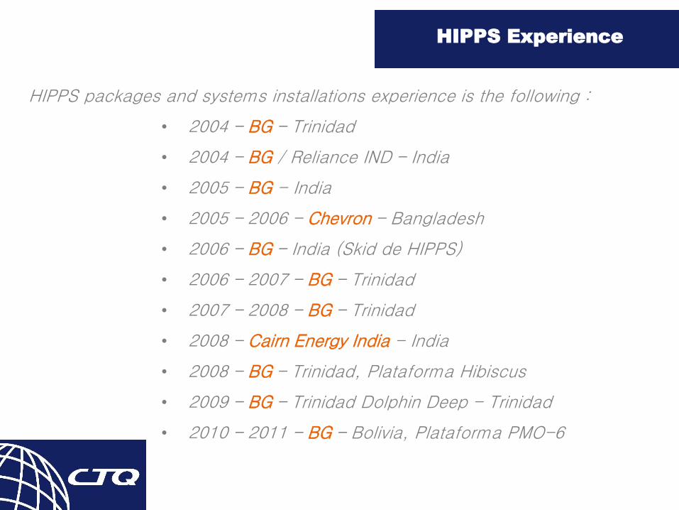
HIPPS Experience
HIPPS packages and systems installations experience is the following :
• 2004 – BG – Trinidad
• 2004 – BG / Reliance IND – India
• 2005 – BG - India
• 2005 – 2006 – Chevron – Bangladesh
• 2006 – BG – India (Skid de HIPPS)
• 2006 – 2007 – BG – Trinidad
• 2007 – 2008 – BG – Trinidad
• 2008 – Cairn Energy India - India
• 2008 – BG – Trinidad, Plataforma Hibiscus
• 2009 – BG – Trinidad Dolphin Deep - Trinidad
• 2010 – 2011 – BG – Bolivia, Plataforma PMO-6

Case Study-Bibiyana
The Bibiyana gas field was developed by Unocal in the countryof Bangladesh using HIPPS as the first protection system.
MYANMARMYANMAR100 km100 km
DhakaDhaka
INDIAINDIAUnocal acreageUnocal acreage(100% W.I.)(100% W.I.)
Moulavi Bazar
discovery
14
12
B A N G L A D E S HB A N G L A D E S H
Bibiyana
discovery
7
13
Jalalabad
gas field
MYANMARMYANMAR100 km100 km100 km100 km
DhakaDhaka
INDIAINDIAUnocal acreageUnocal acreage(100% W.I.)(100% W.I.)
Unocal acreageUnocal acreage(100% W.I.)(100% W.I.)
Moulavi Bazar
discovery
14
12
B A N G L A D E S HB A N G L A D E S H
Bibiyana
discovery
7
13
Jalalabad
gas field
The Bibiyana gas field is located at the NE corner of Bangladesh, at Block 12. Approximately 150 km from the capital of Dhaka.
PROJECT DESCRIPTION:
The project will be designed for a total capacity of over600 MMSCFPD. The Bibiyana field will be developed fromThe drilling of wells in two separate clusters.The southern cluster will contain the main gas processing facilities.The north cluster is located 4 km from the main cluster.Both will produce approx. 300 MMSCFD of total production.
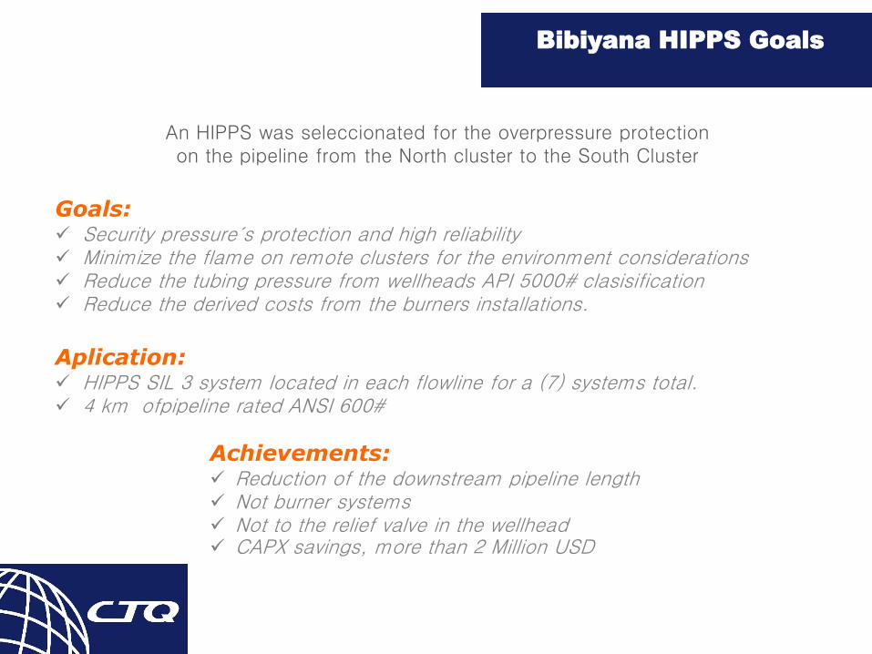
Bibiyana HIPPS Goals
An HIPPS was seleccionated for the overpressure protection on the pipeline from the North cluster to the South Cluster
Goals: Security pressure´s protection and high reliability Minimize the flame on remote clusters for the environment considerations Reduce the tubing pressure from wellheads API 5000# clasisification Reduce the derived costs from the burners installations.
Aplication: HIPPS SIL 3 system located in each flowline for a (7) systems total. 4 km ofpipeline rated ANSI 600#
Achievements: Reduction of the downstream pipeline length Not burner systems Not to the relief valve in the wellhead CAPX savings, more than 2 Million USD
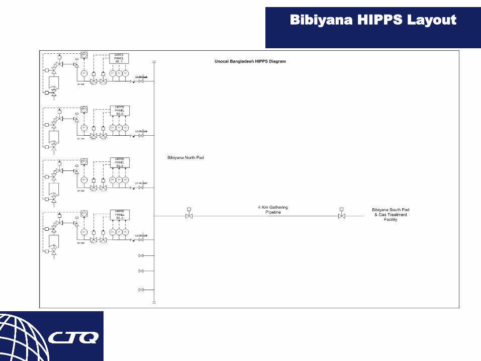
Bibiyana HIPPS Layout
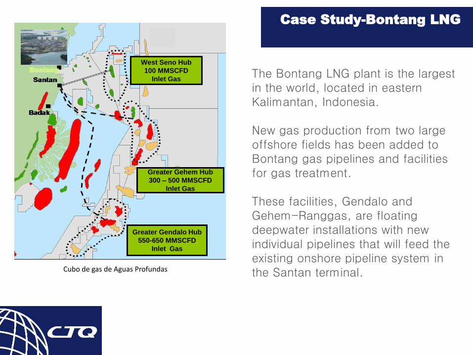
Case Study-Bontang LNG
The Bontang LNG plant is the largest in the world, located in eastern Kalimantan, Indonesia.
New gas production from two large offshore fields has been added to Bontang gas pipelines and facilities for gas treatment.
These facilities, Gendalo and Gehem-Ranggas, are floating deepwater installations with new individual pipelines that will feed the existing onshore pipeline system in the Santan terminal.Cubo de gas de Aguas Profundas
West Seno Hub
100 MMSCFD
Inlet Gas
Greater Gehem Hub
300 – 500 MMSCFD
Inlet Gas
Greater Gendalo Hub
550-650 MMSCFD
Inlet Gas
Bontang

Limitations and Considerations
BONTANG LNG
Pressure limitations existing in the pipeline:
1. HP pipelines from Gendalo and Gehem-Ranggas will supply gas at a pressure of approximately 1000 psig.
2. The existing piping protection system could not withstand higher pressures due to new production.
3. 910 to 940 psig of the pipeline pressure
4. The intake pressure of the Bontangplant is set at 700 psig
5. A pipeline protection system must be used
Technical Considerations for PressureReduction:
1. A full flow relief with a burner would require a very large burner (600 + MMSCFD) for each offshore gas pipeline.
2. Customer determined the most effective protection of existing pipeline will be through a HIPPS system
3. Great reduction of burning to the atmosphere
4. Conservation of natural resources
5. Economic justification through the reduction of lost revenues and the Capex of the construction of burner systems.
Under the new regulations, a special SIS called HIPPS canbe applied instead of traditional mechanical relief devices.
A risk assessment is conducted to determine the SILrequirement for the HIPPS system.
A properly applied HIPPS system mitigates the risk ofoverpressure of the system safely without the need for theburning of natural hydrocarbon resources and theenvironmental problems that the burning represents.
CONCLUSIONS