sewage lagoons - usaid
TRANSCRIPT
Sewags lagoons for develo ing countries. 628 628.35h Dept. of Housing and Urban Development,
.354 D)419 Washington, D.C.
D419 - j Sewage lagoons for developing countries.
Jan. 1966.IDEAS AND METHODS O g
302/2/1 Sewage Lag L ' Bibliography: p. 33-35.
At head of title: Ideas and methods exchange no. 62; 302/2/1/ Sewage lagoons. Prepared for A.I.D.
1.Sewage lagoons. i.Title.
SEWAGE LAGOONS for developing countries
Prepared for the Agency for international Development
DEPARTMENT OF HOUSING AND URBAN DEVELOPMENT WASHINGTON, D. C. 20410
oL0 is AMNY)

Ideas and Methods Exchange No. 62
302/2/1 Sewage Lagoons
SEWAGE LAGOONS FOR DEVELOPING COUNTRIES
Prepared for
The Agency for International Development
DEPARTMENT OF HOUSING AND URBAN DEVELOPMENT
WASHINGTON, D. C. 20410.
January 1966
FOREWORD
The publications in the Ideas and Methods Exchange Series present ideas and useful experiences that will help urban development and housing advisors of the Agency for International Development in providing technical assistance to developingcountries.
This publication on sewage lagoons, which was prepared at the request of A. I. D., is addressed to one of the major problems faced by many developingcountries -- that of providing safe and economical means of sewage treatment and disposal.
Sewage lagoons, also called stabilization ponds or oxidation ponds, have been successfully used in th3 United States and in a number of the developing countries. They are a recognized means of sewage treatment and have two advantages for developing countries: (1) Their construction requires principally land and labor - both local commodities, and (2) they are generally cheaper to install than more conventional treatment plants. Unfortunately, the literature dealing with these facilities is generally of a fragmentary and sometimes higbly technical nature.
The authors of this publication, are Thomas Callaway, Housing Advisor, and Berrard Wagner, International Technical Affairs Officer, both of the Departmentof Housing and Urban Development. In it, they have assembled and summarized pertinent data on sewage lagoons, including their advantages and disadvantages,location, design, construction and maintenance. It therefore should be invaluable to technicians in reaching decisions on types of facilities that may be used and the conditions under which sewage lagoons are practical.
Two things, should be emphasized: First, this publication is not a substitute for the services of competent public health personnel and trained sanitary engineers;second, sewage lagoons should not be regarded as a panacea to end, once and for all,the problem of sewage disposal. While significant knowledge exists, additional research remains to be done. Revised versions of this publication will be'prepared as additional facts become available. Nevertheless, the information now available is promising enough to warrant dissemination at this time.
JamesA or Assistant Administrator
i1i
PREFACE
Many cities in developing countries lack acceptable community sewage disposalsystems. The failure to provide safe, effective means of disposing of human andother wastes present problems, the seriousness of which cannot be overestimated.This is particularly true in cities with rapidly expanding populations and high densities.In some cases individual households have no facilities at all, or at best, only pitlatrines. In other instances, wastes from dwellings, schools, hospitals, commercialand industrial buildings are sometimes discharged into cesspools or into septic tankswith inadequate means of disposing of the effluent. This frequently results in contamination of adjacent areas and of the ground water which finds its way into streamsand water supply wells. Even cities with sanitary sewers often do riot have satisfactory treating facilities and raw sewage is sometimes discharged into rivers andstreams which may also be sources of drinking water for both livestock and humans.
The cost of constructing adequate treatment plants often discourages theirinstallation in cities with limited budgets. However, treatment is possible by meansof sewage lagoons which are usually less expensive than more conventional methods.
This publication summarizes the essential information on sewage lagoons in aform readily understood by laymen as well as by specialists. The Agency for International Development, therefore, believes that it will be useful to urban developmentand housing advisors and a guide to their host country counterparts in reachingdecisions and planning for sewage treatment facilities.
Osborne T. BoydDeputy Director for Housing and
Urban Development Agency for International Development
V
ACKNOWLEDGMENTS
The authors wish to acknowledge the contribution made by Walter Evans, now with the Federal Housing Administration, in conducting the preliminary research for this publication. They also wish to express their appreciation to J. Robert Dodge, Office of International Housing, for reviewing it and to Messrs. Peter Rowan, RalphPorges, G. Walton, and K.M. Mackenthun of the Public Health Service, Department of Health, Education and Welfare, for their valuable comments on the draft paper and for suggestions for improvement. Valuable comments were also received from Harry J. Eby, Agricultural Engineer, Agricultural Research Service, U.S. Department of Agriculture, and from Arthur E. Williamson of the Department of Public Health of the State of Wyoming. Richard C. Knight, Harold Robinson, Arthur C. Curtis, John Moller and William H. Coster of the Agency for International Developmerit have likewise favored the report with their review, and Neil A. Connor of the Federal Housing Administration has contributed valuable observations. Last but not least, A. Harold Taylor, Chief Health Officer of Nairobi, Kenya, has been most helpful and generous, not only with practical advice, but also in making available photographs of completed and successfully operating lagoons in the Nairobi area.
vii
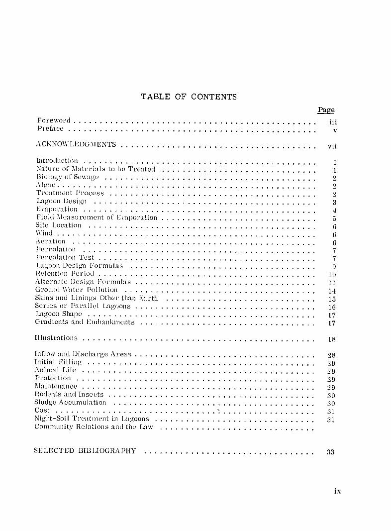
TABLE OF CONTENTS
F.ge Foreword................................................ M
ACKNOWLEDGMENTS .............................................. vii
IntroductiO ................................................. 1 Nature of Materials to be Treated .............................. 1 Biology of Sewage ......................................... 2
a e 22.................................................. Treatment Process ............................................... 2 Lagoon Design... .................................................. 3 Evaporation .......... .............................................. 4 Field Measurement of E'vaporation .................................... 5 Site Location ........... ............................................ 6 Wind ........... .................................................. 6 Aeration .......... ............................................... 6 Percolation .......... ............................................. 7 Percolation Test ................................................... 7 Lagoon Desigm Formulas ........ .................................... 9 Retention Period ................................................... 10 Alternate l)esign Formulas .......................................... 11 Ground Water Pollution.. .............................................. 14 Skins and Linings Other than Earth ....... ............................. 15 Series or Parallel Lagoons .......................................... 16 Lagoon Shape ......... ............................................ 17 Gradients and Emiibankments .......................................... 17
Illustrations ......... ............................................. 18
Inflow and Discharge Areas .......................................... 28 Initial Filling..................................................... 29 Animal Life ......... ............................................. 29 Protection .......... .............................................. 29 Maintenance .................................................... 29 RIodents and Insects ................................................ 30 Sludge Accumulation ........ ....................................... 30 Cost ....................................... ................ ... 31 Night-Soil Treatment in Lagoons ...................................... 31 Community Relations and the Law. .................................
SELECTED BIBLIOGRAPHY ....................................... 33
ix
INTRODUCTION
Sanitation, particularly the disposal of sewage, has always been a problem to mankind. Wherever man has lived, parasitic disease-causing pathogens have also lived. Sewage has been and still is one of the major sources of disease, especially in areas where proper or effective sanitary measures are lacking. In many part&of the world, especially the developing areas, simple pit privies or latrines are often the only provision for handling human wastes and frequently there are no sanitary facilities at all. Even where sewage systems exist, streams, ponds and nearby wells -- all sources for domestic water supply -- are likely to become contaminated. The lack of better sanitary facilities stems from a lack of knowledge of hygiene and corrective techniques, as well as a dearth of funds necessary for the provision of normal treatment plants. However, a reasonably simple and economic solution for the treatment of sewage exists which requires mainly sufficient land and human effort -sewage lagoons.
Sewage lagoons, or stabilization ponds, have been constructed in large numbers in the United States and elsewhere; e. g. , Canada, Latin America, Holland, Germany, South Africa, Kenya, Rhodesia, Tanzania, Zambia, and Australia. Only a few failures have resulted, usually from human error in the desig-n stage, involving capacity, leakage, or flow control. The usual objections to such a system which include bad odors, objectionable solids, and poor appearance may usually be overcome by proper location, adequate planning, proper loading and maintenance. Where reasonably priced land is available and when they are properly located, designed and built, lagoons provide efficient, low-cost sanitary domestic sewage treatment.
NATURE OF MATERIALS TO BE TREATED
Sewage lagoons are best suited for treatment and disposal of domestic wastes and some forms of industrial waste. Complex industrial waste originating in dye works, milk processing plants, slaughter houses, etc. sometimes requires special treatment and cannot be readily handled by sewage lagoons alone. Cases are on record of lagoons handling dairy and slaughter house waste, but their design is subject to special consideration.
Physically, normal domestic sewage is approximately 99. 9',0' water, plus small amounts of suspended and dissolved solids in the form of both organic and inorganic matter. Fresh sewage is usually alkaline, tending to acidity with time, as it stabilizes. The strength of sewage depends on the relative per capita quantity of water used by the community and on the amount and nature of industrial wastes, etc. , entering the system. In appearance, sewage is generally cloudy and has a slight musty or oily odor.
Chemical characteristics of sewage involve complex organic materials from feces, urine and other wastes, including inorganic material. Nitrogen compounds include proteins, urea, amines and amino acids; non-nitrogenous substances include cellulose, fats and soaps.
BIOLOGY OF SEWAGE
The biology of sewage involves aerobic bacteria utilizing free oxygen and anaerobes which are active in the absence of free oxygen. Though most sewage bacteria live on dead organic matter, a few are parasitic.
Stabilization of sewage is brought about by bacteria and algae. Bacteria digest and oxidize sewage; and algae through photosynthesis, produce oxygen required for aerobic bacterial amcion. The oxygen cycle of decomposition is complete and continuous, as oxidation forms carbon dioxide, which is used by algae, resulting (under certain conditions) in the creation of additional oxygen. Anaerobic action creates ammonia (a nitrogen compound) which is in turn stabilized by oxidation through aerobic action. The goal of sewage treatment is therefore a natural cycle, achieving stability without the creation of offensive conditions. The amount of oxygen necessary for aerobic decomposition is called Biochemical Oxygen Demand, or B.O.D. The rate of oxygen required is highest during the first 5 or 6 clays and declines steadily thereafter. It may accelerate again about the 20th clay after which it gradually diminishes over an indefinite period of time.
Objectionable odors may result from the emanation of hydrogen sulfide caused by biochemical action under anaerobic conditions and at p1l values (hydrogen ion concentration) below approximately 7. 5. However, in ponds having a high dissolved oxygen concentration, the formation of sulphide ions and of free hydrogen sulphide should be prevented and no odors should occur. Satisfaction of the B.O.D. depends on sewage strength and a variety of conditions, including temperature. The higher temperatures in tropical areas are -- in this instance -- an asset in that B. 0. D. satisfaction (70% to 90')) can be achieved in a much shorter time than in cooler climates.
ALGAE
Algae are generally one-celled microscopic organisms found in a variety of forms ranging from spheres to rods. Living in the lagoon water, algae use the byproduct of bacterial action and the energy of the sun in the process of photosynthesis to produce oxygen, which plays a vital role in the sewage treatment process. Most algae are harmless to humans, but large quantities of certain forms of algae may be harmful to humans and livestock or cause undesirable taste where purified effluent (after further treatment) is to be used for cooking or drinking. (The latter is not recommended, unless reliable tests indicate that the water is safe for drinldng purposes.)
Green in color intemperate climates and green-gray in hotter areas, algae usually fioat below the surface of the pond. During periods of intense sunlight they may rise to the surface and increase their oxygen producing activity. Icing conditions retard allgal activity, with a corresponding slowing down of the treatment process, thus necessitating longer liquid retention periods. Algae do not produce oxygen at night, i.e. , in the absence of light and sunshine. Also, snow cover over ice will cause a blackout of algal activity and consequently a loss in the production of oxygen.
TREATMENT PROCESS Lagoons provide a simple but extremely efficient method of treatment in that raw
sewage from the collection system is discharged into a shallow "dish" where it is
2
treated by the same process of oxidation to be found in lakes and streams with the advantages of increased speed owing to controlled conditions and the reduction of pollution of natural waterways. The system involves the retention of sewage in the lagoon until the BOD is adequately satisfied (70','1 to 90%), after which the effluent is dischargedinto local streams, or, in a 'balanced" system, retained as a medium to support the continuing process at an optimum level. The solids are converted to sludge which settles on the bottom of the pond. Accumulation of sludge is at a very slow rate, estimated by various sources at a fraction of an inch to a maximum of 3-1/2 inches per annum, allowing many years of cfficient service from a properly designed lagoon without a drastic reduction in capacity.
However, sewage lagoon effluent s is the case with the effluent from conventional sewage treatment plants) is not necessarily free of pathogenic organisms and may require additional treatment and/or chlorination. Ifnot chlorinated, its use should be restricted to irrigation of non-edible crops. The degree of contamination should be checked periodically and its use determined accordingly.
It is difficulb to arrive at a definition of what constitutes stabilized sewage. The degree of s abilization will, of course, depend upon the use to which the effluent is to be put and on the standards that are applied to achieve such stabilization. The French, in 1950, defined stabilized sewage as follows:
1. The treated water should not contain more than 30 milligrams of suspended matter of all kinds per liter;
2. Before and after 5 clays of incubation at 300 centigrade it should not give off any foul or ammoniacal odor and have a negative putreciability test;
3. It should not contain any substance toxic to fish or harmful to animals living in water into which it is discharged;
4. In 5 clays it should not absorb more than 40 milligrams of dissolved oxyger' per liter at 18° centigrade (BOD test).
Wlerever possible, efforts should be made to engage the services of properlyqualified personnel, i.e. , public health officials or sanitary engineers, to test the resulting effluent as well as to advise on lagoon plalming and design generally.
LAGOON DESIGN
Proper planning is vital in order to elininate possible future problems and to keep construction operations and maintenance costs to a minimum.
In addition to domestic sewage many types of minor industrial wastes can be handled by normal lagoon systems. A check on the type of industries using the collection system will determine whether or not special treatment facilities must be provided. One the nature of the sewage is determined, the quantity is the next factor to be arrived at. The quantity estimate is based on the following elements:
hRsi liquid wu. tr-uiz .rc.,,i. tion: with central water supplySi, In communities systems. liquid wastes can usually '.e assumed to be equal to total daily water consumption. In many developing countries this may be assumed to be 20 to 40 gallons
3
per person per day. However, individual and careful estimates are necessary. Exceptions requiring adjustment of the figure would include subtraction of any large volume of water used for such purposes as irrigation, and the addition of the total volume of water originating from other sources (such as private water supply systems installed by some industries) but discharged into the common collector system.
Where a community secures its water supply from individual or communal wells, cistelns, springs, and only part from a central mnicipal supply, careful studies should be made to allow a reasonably accurate estimate of consumption in terms of gallons per capita per day. This will then be multiplied by the numLber of persons served by the collector system, to which must be added any additional amounts of waste from other sources. Wiere a sewer system exists, its actual discharge will, of course, indicate the volume of consumption. lowever, in most instances only fractional systems may exist, entirely inadequate, and making no allowances for future requirements and expansion.
It may not always be possible to maintain an adequate licjuid depth in the lagoon if water consumption is insufficient or fluctuates significantly. For this reason, in areas where severe water shortages occur, it is necessary for a water supply to be added adjacent to the lagoon or lagoons.
I i/ltr ti: Infiltration of water into sewer systems results, from poorly constructed and maintained sewer systems, cracked pipes, leaking manholes, pipes below the ground water table and illegal connections; in other words, any water not entering the system from desigped or luiown points. Infiltration may be substantial and often requires an increase in designi capacity of the lagoon to allow for the rainy season, although there may be no problem during dry weather.
In the temperate regions, daily average and peak flows should be increased by as much as 30' ' to allow for wet weather infiltration, while an increase of 50"() may be necessary in tropical areas during the rainy season.
In order to insure a minimumn design figure for flow in the dry season, no adjustment which would assume increase through infiltration, should be made for this period.
Otherfactors influencing thevolume of water in the lagoon are percolation and evaporation. Though losses through percolation often gradually decline, this factor should be estimated through tests once an actual site is chosen. Evaporation is an extremely variable figure (according to climatic zones) but losses can be estimated for a given region once the surface area of the lagoon(s) is lkown. laving established daily rates, maximum and minimum seasonal flows at the outfall and losses from the jagoon(s) itself, it is then possible to determine whether or not the water level of a lagoon can be maintained within the desigied maximum and minimum depth range.
EVAPORATION
As noted above, evaporation plays an important role in determing the levl of water maintained in a lagoon, particularly in tropical areas. The amount of evaporation at a given moment is dependent on the temperature, humidity and wind velocity. As a result, it is difficult to predict with any accuracy the evaporation rate for any short period of time. Fortunately, such losses are only critical on a seasonal basis, for which reasonably accurate averages are lmown for most regions of the world.
4
However, in certain areas as much as 20% of the influent may be lost through evaporation.
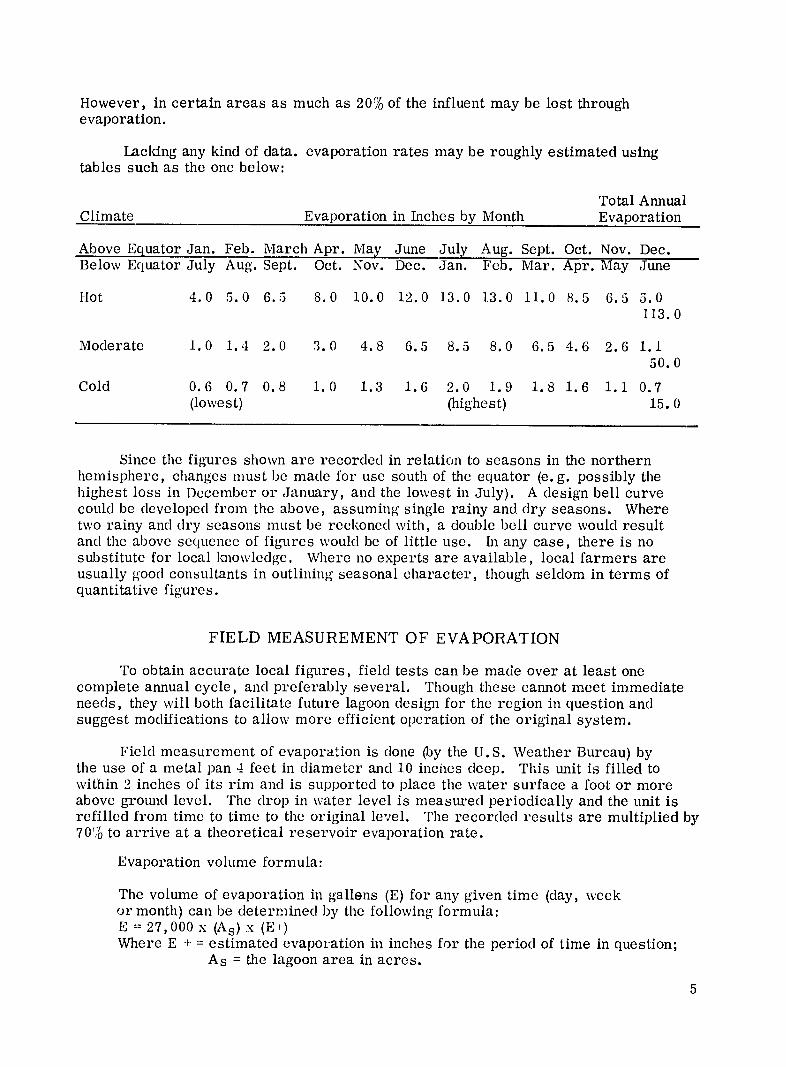
Lacking any kind of data. evaporation rates may be roughly estimated using tables such as the one below:
Climate Evaporation in Inches by Month Total Annual Evaporation
Above Equator Jan. Feb. Below Equator July Aug.
March Apr. Sept.
May Oct. Nov.
June Dec.
July Jan.
Aug. Sept. Feb. Mar.
Oct. Apr.
Nov. May
Dec. June
Hot 4.0 5.0 6.5 8.0 10.0 12.0 13.0 13.0 11.0 8.5 6.5 5.0 113.0
Moderate 1.0 1.4 2.0 3.0 4.8 6.5 8.5 8.0 6.5 4.6 2.6 1.1 50.0
Cold 0.6 0.7 (lowest)
0.8 1.0 1.3 1.6 2.0 1.9 (highest)
1.8 1.6 1.1 0.7 15.0
Since the figures shown are recorded in relation to seasons in the northern hemisphere, changes must be made for use south of the equator (e. g. possibly the highest loss in December or January, and the lowest in July). A design bell curve could be developed from the above, assuming single rainy and dry seasons. Where two rainy and dry seasons must be reckoned with, a double bell curve would result and the above sequence of figures would be of little use. In any case, there is no substitute for local knowledge. Where no experts are available, local farmers are usually good consultants in outlining seasonal character, though seldom in terms of quantitative figures.
FIELD MEASUREMENT OF EVAPORATION
To obtain accurate local figures, field tests can be made over at least one complete annual cycle, and preferably several. Though these cannot meet immediate needs, they will both facilitate future lagoon design for the region in question and suggest modifications to allow more efficient operation of the original system.
Field measurement of evaporation is clone (by the U.S. Weather Bureau) by the use of a metal pan 4 feet in diameter and 10 inches deep. This unit is filled to within 2 inches of its rim and is supported to place the water surface a foot or more above ground level. The drop in water level is measured periodically and the unit is refilled from time to time to the original level. The recorded results are multiplied by 70% to arrive at a theoretical reservoir evaporation rate.
Evaporation volume formula:
The volume of evaporation in gallons (E) for any given time (day, week or month) can be determined by the following formula: E = 27,000 x (As) x (E-) Where E + = estimated evaporation in inches for the period of time in question;
As = the lagoon area in acres.
5
SITE LOCATION
Though availability of land is a controlling factor, sites at lower elevations than the collection system are economically preferable in order to eliminate the need for costly lift stations. Objections on the part of the local inbabitatnt (usually psychological can often be overcome by careful explanation, and, if possible, visits to existing lagoon systems. Zoning, or distance restrictions written for traditional waste disposal plants are also a factor, though from a practical point of view a minimum distance of 1/4 mile from a housing area has proven satisfactory. The direction of prevailingwinds (during the day and at night time) is also an important factor in locating lagoonswith respect to housing.
WIND
The lagoon layout should always be planned so that the direction of the prevailingwind is never along the line of flow thus short-circuiting sewage from inlet to outlet or retarding the normal flow. Obstructions which restrict air movement (including buildings) should be avoided. Wind induces wave action and sub-surface currents which are necessary to stimulate oxidation. However, winds in excess of 30 miles per hour may create wave action which in turn may cause crosion' along the edges of the lagoon. This can be prevented by installation of concrete blocks or slabs at the water-edge (see also "Gradients and Embankments').
In order to assure a clear sweep for winds, seasonal changes in direction and relative speeds should be Imown. As pointed out above, farmers, fishermen, or others who work outdoors year round are usually excellent sources of general climatic data if local fig-ures are not available. As with evaporation, however, long-termobservations should be made to broaden background data for future designs and improvements in primary systems.
Because local wind conditions are affected by a number of factors, including temperaturc, heights of vegetation, etc. , a generalization concerning obstructions in the imnediare vicinity of the lagoon is difficult to make. In the average case, however, one might allow a clear distance of 5 to 6 times the height of any groups of trees or bushes from [he lagoon. In the case of isolated buildings, a clear sweep equal to the height or wid.h of the structure, whichever is greater, is generally sufficient. In any case, a minimum clear sweep of '300 feet free of all but isolated obstructions should provide adequate wave action.
AERATION
The low cost of lagoon treatment, free of aiy mcchanical aids, is a factor which makes the system a vry appealing one -- particularly in developing nations and communities. lHowever, where necessary and economically feasible, various means of artificial aeration can be used to induce circulation and wave action, and thus oxygenabsorption. This means can be used to revive systems which for some reason have becom(c anaerobic, or to add capacity to existing facilities where the problem is
* U.S. experience indicates that erosion is not serious until lagoons reach an area of 30 acres or larger.
6
immediate, or where lack of funds or land delay the construction of additional lagoons.Aeration can also be used to slow or prevent icing-over of lagoons located in colder climates.
Under this method, a blow supplies air to a system of perforated pipes placed on the lagoon bed. The rising air bubbles induce slight circulation and increase absorption of oxygen. Slight foaming may be noted over the pipelines. An American engineering company has installed a system utilizing a 10 h. p. blower which delivers air at the rate of 150 cubic feet per minute. Using 7500 feet of plastic tubing laid parallel and spaced from 10 to 30 feet apart, the system has a potential capacity of 600 homes, orapl)proximately 3000 persons. A similar system is being used with some success in reviving polluted lakes in Sweden. Other systems include agitation of the lagoonsurface by water spray.
Where ponds are desigmedl to cause flow of sewage from higher to lower levels,intervening baffles tend to agitate the water, and thus increase aeration. It should be noted, however, that sludge tends to build up on the high side of the baffles. Other attemipts to increase aeration include changing levels through the use of a series of steps at the inflow point, or the use of a series of small ponds each lower than the last. These methods have been used when the flow is low clue to dry weather, but the value of results cannot be predicted with any degree of accuracy.
The p)racticality of artifically aerated lagoons, however, should not be overestimated. An extended aeration process is no substitute for the natural treatment )rocess using algae to provido oxygen. Therefore, wherever possible, lagoons should
be designed to function without artificial aeration.
PERCOLATION
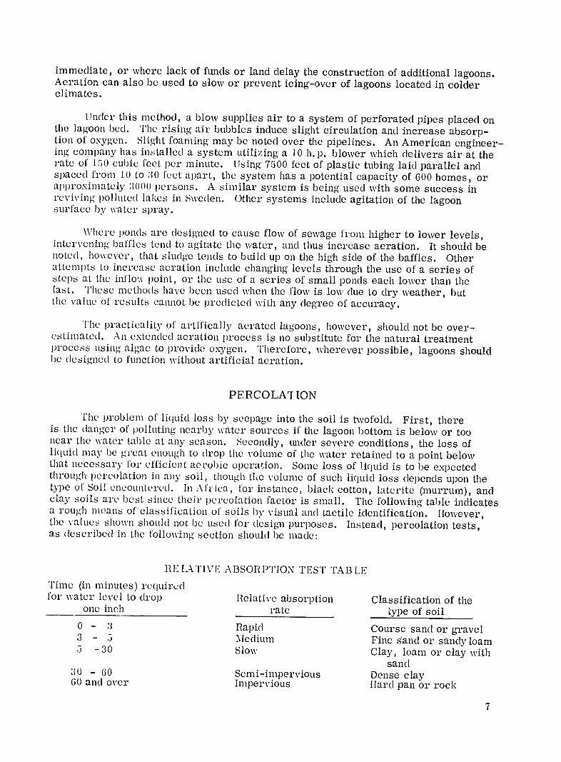
The problem of liquid loss by see)age into the soil is twofold. First, there is the danger of )ollIting nearby water sources if the lagoon bottom is below or too near the water table at any season. Secondly, under severe conditions, the loss of liquid may be great enough to drop the volume of the water retained to a point below that necessary for efficienit aerobic operation. Some loss of liquid is to be expectedthrough percolation in any soil, though the volume of such liquid loss depends upon the type of Soil encountered. In Africa, for instance, black cotton, laterite (murrum), and clay soils are best since their percolation factor is small. The following table indicates a rough means of'classification of soils by visual and tactile identification. However,the values shown should not be used for design purposes. Instead, percolation tests, as described in the following section should be made:
II.[ATIVE ABSORPTION TEST TABLE
Time (in minutes) requirvdfor water level to drop Relative absorption Classification of the
one inch rate type of soil 0 - 3 Rapid Course sand or gravel:3 - 5 Medium Fine sand or sandy loam
-30 Slow Clay, loam or clay with sand
30 - 60 Semi-impervious Dense clay60 and over Impervious lard pan or rock
7
Note: The first two types of soil are not suited for lagoon purposes unless water retention is assisted by the installation of a waterproofing skin at the lagoon bottom.
PERCOLATION TEST
Before finally choosing a site, percolation tests should be made to allow an accurate estimate of initial liquid loss, and the relative danger of pollution of any nearby water supply. Tests should be made at the depth of the projected lagcon bed. To this end, it will be necessary to dig a pit large enough to allow convenient working area at the desired level, except where the natural grade is intended as the lagoon bottom. A square hole one foot to a side, is dug to approximately 1'-6" depth, below the proposed level of the lagoon bottom. The test hole is then filled xith water to a known depth (usually 6 to 12 inches). After the water has disappeared, the hole is again filled to the same depth, and the time for its absorption noted. This time (in minutes) is divided by the depth in inches to give the time required for the water level to drop one inch. This process is then repeated at several points over the test site particularly where changes in soil character are evident. The resulting factors are then averaged to arrive at a single design factor.
It should be noted that sludge deposits slowly seal the lagoon bottom, reducing losses to a negligible point in relatively impervious soils, and drastically reducing percolation in even the worst cases. For example, experience indicates that an initial loss as high as 6 inches per day may gradually decline to as little as 1/4' to 3/4" per day.
LAGOON DESIGN FORMULAS
No exact science of lagoon design has been developed so far. Early designs required a total pond area of one acre for every 100 to 200 persons while later developments and experience led to much higher loadings. In Africa, lagoons are operating satisfactorily today with total pond areas of one acre for every 600 to 1, 000 persons.H owever, such "rules of thumb" can be misleading or even dangerous. So many variables enter the picture that each case should be investigated individually.
In designing a lagoon, it is necessary to establish the capacity which is the area of the lagoon times the depth. To arrive at these figures, it is essential to obtain the following basic information:
1. The maximun volume of liquid entering the lagoon which is the sum of the basic liquid waste-water consumption of the community which the lagoon serves, plusliquid entering the system through infiltration, rainfall, etc.
2. Minimum volume of liquid to be retained in the lagoon, which is the basic liquid waste water consumption minus the loss of liquid from the lagoon from seepage and evaporation.
3. The strength of the sewage in terms of BOD per person per day and the loading of the pond in pounds of BOD per acre per day.
4. The retention period necessary for the sewage to reach a BOD reduction of 70% to 90%.
Where sanitary engineers or competent public health officials are available, it is of course advisable to seek their aid in determining BOD rates, loading per acre, etc. Where such information is not available, the following formulas may be used in planning the necessary lagoons.
1. Surface Area
As (acres required) Population served x pounds of 5-day BOD per person per day (0. 12 to 0.20)1/
Design BOD loading pounds per acre per day (20 or more)
Note: In the State of Missouri (USA), BOD loadings of up to 68 pounds of 5-day day (200C) BOD per acre have been successfully employed. In some areas and under certain conditions up to -- or over -- 10V pounds maybe feasible. In Nairobi, Kenya, BOD loadings of 54 pounds were found to work out satisfactorily, and 200 to 250 pounds were used in two-pond systems.
1/ This formula was suggested by the Public Health Service, United States Department of Health, Education and Welfare.
9
In Pretoria, for instance, 145 pounds BOD per acre per day were adopted in the primary pond of a multiple-pond system, amounting to an equivalent of 1, 200 persons per acre or 50,000 gallons per acre per day. Local climatic conditions greatly influence design and operation and should not be underestimated.
2. Depth
For reasons of economy and efficient operation, the depth of the liquids in lagoons should normally range somewhere between 2 and 6 feet; with minimum depth of 2 to 2-14 feet, vegetation is not likely to grow at the bottom of the pond. Shallower ponds (2 to 5 feet) are best in cool climates in order to allow for maximum penetration of sunlight. Because of the higher angle of the sun in tropical climates, deeper sunlight penetration permits deeper ponds (3 to 6 feet). Experience in various parts of Africa indicates that a depth of 4 feet is usually satisfactory.
3. Capacity
With the minimum and maximum desired depths established, and using the surface area figures calculated above, formulas below:
the volume of the lagoon is readily found with the
Minimum lagoon capacity in cubic feet
= (surface area 43,560
in acres) x (minimum depth in feet) x
Maximum lagoon capacity in cubic feet
= (surface area in acres) x (maximum depth in feet) x 43,560
Because the efficient operation of lagoons depends on maintaining optimum maximum and minimum liquid depths, these must be taken into account in the design of a lagoon. This will require a careful study of local annual temperature and rainfall data. For eyample, provision must be made to accommodate the maximum infiltration which generally occurs in the rainy season and to maintain an adequate minimum liquid level iu the lagoon during the dry season when usually minimum infiltration and maximum evaporation occur during the same period.
RETENTION PERIOD
A minimum retention period must be determined in order to induce the reduction of BOD to a point allowing discharge of effluent into a normal waterway or irrigation system. In the United States, lagoons of the flow-through type, receiving raw sewage, normally employ 60 to 90 days retention. In tropical countries this is likely to be reduced but should not be less than 20 to 25 days.
A practical retention time is based on the rate of flow balanced against an efficient minimum and economically maximum pond size. If the volume of influent is roughly equal to the volume of liquid remaining after percolation and evaporation losses to keep the lagoon level within acceptable minimum and maximum limits, no effluent will result and the system can be termed balanced. As a balanced lagoon system is sometimes desirable, the lagoon size can be planned within reasonably flexible limits to achieve this end. Operating a lagoon as a closed or balanced system during the dry season, and
10
allowing for effluent at a rate within the desired retention time during the season of rains is one of the several means of operating lagoons in a tropical climate.
Hydraulic retention time can be determined by the following formula:
T maximum = 7.48 (C maximum) T minimum = 7.48 (C minimum)G m G
m
Where T. max. = maximum retention time (days) T. min. = minimum retention time (days) C. max. = maximum capacity (cubic feet) C. min. = minimum capacity (cubic feet) Gm = gallons per day influent
7.48 = gallons per cubic foot
The optimum retention time will depend upon organic loading, well as hydraulicas loading. The lower the loading in ponds of 5 day BOD per per acre per day, the greaterthe volume of liquid. This permits a longer retention period and a correspondingly greater reduction of BOD.
ALTERNATE DESIGN FORMULAS
In addition to the above, the following series of formulas has been developed bythe African Housing Board, Lusalm (Zambia) and the Council for Scientific and Industrial Research (CSIR) in Pretoria, South Africa. As well as arriving at a set of designfigures, the following set of formulas can be used to predict the effectiveness of a multiple pond system. (Note that gallons used in these formulas are Imperial gallons, one Imperial gallon = 1.2 U.S. gallons = 4.536 litres.)
For design purposes, a given level of BOD contribution per person should be based on actual measurement. Where this is impossible, a figure must be assumed. This figure is variously noted as 0.12 pounds per day to 0.20 pounds per day, depending on such factors as local water consumption and dietary habits of the people.
Sewage strength in terms of BOD can then be arrived aL by the formula:
Per person per day BOD in pounds x 105
Sewage BOD (in mg. per liter BOD) =Flow in gallons per person per day
For instance, for a population of 5, 000 persons and an assumed daily flow of 40 gallons per person, the
BODo sewge =(.12)BOD of sewage (40) x 100,000 = 300 mg/litre
Design figures for primary ponds are then calculated by going through the following steps:
11
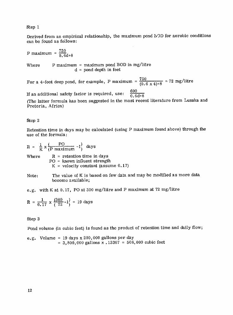
Step 1
Derived from an empirical relationship, the maximum pond bOD for aerobic conditions can be found as follows:
750 P maximum = '0.6d+8
Where P maximum = maximum pond BOD in mg/litre d = pond depth in feet
750
For a 4-foot deep pond, for example, P maximum 0 = 72 mg/litre(0. 6 x 4)+8 600use: 60
If an additional safety factor is required, 0.6d+8
(The latter formula has been suggested in the most recent literature from Lusaka and Pretoria, Africa)
Step 2
Retention time in days may be calculated (using P maximum found above) through the use of the formula:
R = x( PO -I1 days
K (P maximum
Where R = retention time in days PO = known influent strength
K = velocity constant (assume 0. 17)
Note: The value of K is based on few data and may be modified as more data become available;
e.g. with K at 0.17, PO at 300 mg/litre and P maximum at 72 mg/litre
R =x(300 -1) = 19 days0.17 (72
Step 3
Pond volume (in cubic feet) is found as the product of retention time and daily flow;
e.g. Volume = 19 days x 200,000 gallons per day = 3,800,000 gallons x .13367 = 508,000 cubic feet
12
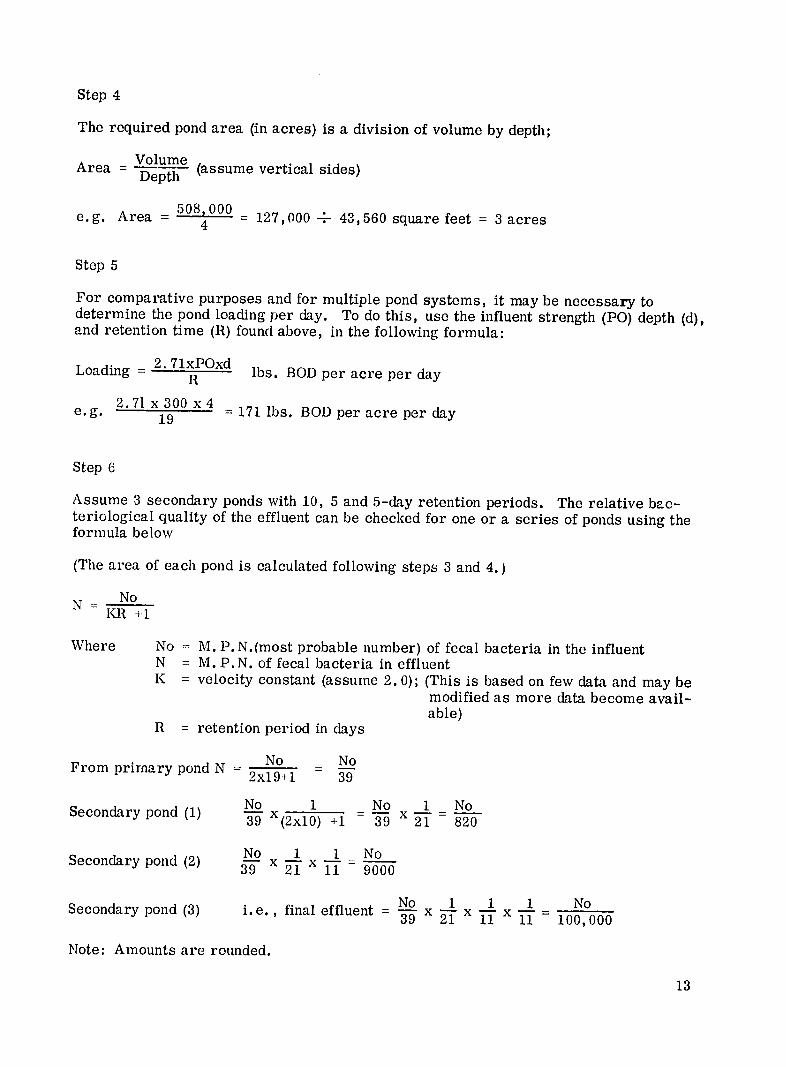
Step 4
The required pond area (in acres) is a division of volume by depth; Volume
Area = -Depth (assume vertical sides)
e~g.Area 508,000 e.g. Area 4 127,000 -- 43,560 square feet = 3 acres
Step 5
For comparative purposes and for multiple pond systems, it may be necessary to determine the pond loading per day. To do this, use the influent strength (PO) depth (d),and retention time (R) found above, in the following formula:
Loadng =2. 7lxPOxd Loading R lbs. BOD per acre per day
e.g. 2.71 x300 x 4 = 171 lbs. BOD per acre per day
Step 6
Assume 3 secondary ponds with 10, 5 and 5-day retention periods. The relative bacteriological quality of the effluent can be checked for one series of ponds using theor a formula below
(The area of each pond is calculated following steps 3 and 4.)
NoN
Where No = M. P. N.(most probable number) of fecal bacteria in the influent N = M.P. N. of fecal bacteria in effluent K = velocity constant (assume 2.0); (This is based on few data and may be
modified as more data become available)
R = retention period in days
From primary pond N = No = No 2x19+1 39
No 1 No 1 NoSecondary pond (1) - X( 2 xl 0 ) +1 - 39 x 21 820
No 1 1 No Secondary pond (2) x 21 1 9000
No1 1 1 _ No Secondary pond (3) i.e., final effluent' =No=3-9 x 1T- x 1T- x 11 No100, 000
Note: Amounts are rounded.
13
- ---
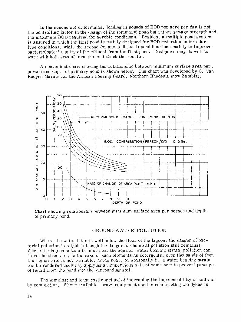
In the second set of formulas, loading in pounds of BOD per acre per day is not the controlling factor in the design of the (primary) pond but rather sewage strergth and the maximum BOD required for aerobic conditions. Besides, a multiple pond system is assured in which the first pond is mainly designed for BOD reduction under odorfree conditions, while the second (or any additional) pond functions mainly to improve bacteriological quality of the effluent from the first pond. Designers may do well to work with both sets of formulas and chock the results.
A convenient chart showing the relationship between minimum surface area per; person and depth of primary pond is shown below. The chart was developed by G. Van Rooyen Marais for the African Housing Board, Northern Rhodesia (now Zambia).
20 -i- ~___- .. --B.I -.
O 0 4 __ ___ -vr- 750 . Iii- RECOMMENDED RANGE FOR POND DEPTHS
Z 40 0-__
_ 30 CONTRIBUTION/PERSON/DAY 0.12!bs.-'B.OD.
fiJ-'-
420
U- 20
20 I 2 4-5-r - I- -----z -- RATE OF CHANGE OF AREA W.RT DEPIH
ofp iar 0
pond. 1T*---*- -- T...
0 1 2 3 4 5 6 7 8 9 10 DEPTH OF POND
Chiart showing relationship between minimum surface area per pcrson and depth of primary pond.
GROUND WATER POLLUTION
\\here the water table is well below the floor of the lagoon, the danger of bacterial pollution is slight (although the danger of chemical pollution still remains). Where the lagoon bottom is inor near the a(quifer (water bearing strata) pollution can travel hundreds or. in the case of such elements as detergents, even thousands of feet. If a higher site is not available, areas near, or seasonally in, a water bearing strata can be rendered useful by applying an iml)er\'iouS skin of some sort to prevent passage of liquild from the )onl into the surrounding soil.
The simplest and least costly method of increasing the impermeability of soils is by compaction. Where available, heavy equipment used in constructing the dykes is
14
useful in compacting the soil. The "sheep's foot" roller may find a useful and literal substitute through the repeated driving across the site of herds of sheep, goats or cattle.
Resistance to percolation loss can also be economically increased by adding to the top layer of soil some locally available earth with water resistant qualities such as clay.The soils should be thoroughly mixed to a depth of a foot or more by spading with possibly a thin, well compacted layer of the heavier soil forming the top skin.
SKINS AND LININGS OTHER THAN EARTH
Unfortunately, the economic factor will rule out the use of processed materials in the lining of lagoons for many developing areas. However, where such materials are readily available, skins can be formed which make even the worst soil types useful for lagoon sites.
1. Bentonite. This is a clay, expands when wet and fills the voids in coarse soils. It may be used as a skin 1 or 2 inches deep, or mixed with other soils in a 5 to 10 percent mix, depending on the characteristics of the local soil. In very loose soils, the value of bentonite may be reduced by diffusion.If it is locally available, it may be an economical solution. However, the price (in the U. S.) of commercial bentonite is approximately $15 to $20 per ton.
2. Soil Cement. Of the processed skins, soil cement is one of the least expensive and in many respects the best means of long term prevention of percolation. Cement is mixed in place with a layer of soil 6 to 12 inches thick. Thorough, methodical spading and tamping, using a fairly dry mix to prevent leaching, gives a satisfactory result. The proportio:n of cement to earth should be determined on the site, depending on the nature of the soil. However, it will probably range between 4 and 8 percent. For extremely poor conditions, such as gravel, it will be necessary to import soil from another area. Among the advantages of soil cement are its resistance tu erosion, and the fact that it is one of the few soil mixtures allowing work (such as sludge removal) without damage to the skin.
3. Asphalts. Spray type asphalts are used extensively in the U.S. at a relatively low cost of 7 to 27 cents per square yard.
(a) Asphalt cutbacks are effective when applied to sands, silts, and other fine gravel soils. Mechanical or hand sprays can be used, the latter requiring slightly more material and at least I week of curing. Penetration is less than one inch.
(b) Thin-film emulsions are best when applied to fine grained soils. Penetration is good and gives temporary protection while sludge is forming its own barriers.
(c) Cut asphalt types are more durable, but must be applied mechanically at a high temperature by skilled personnel. Costs in the U.S. rangefrom 25 cents to a dollar per square yard.
15
(d) Asphalt concretes would only be used in extreme conditions due to high cost (in the U.S. 50 cents to 1 dollar and fifty cents a square yard). A 2 inch layer is laid hot, using a 6% to 8% low penetration asphalt mix.
(e) Asphalt saturated and felt covered mastic core mats are produced for reservoir and pond lining, but again are high (in the U.S. 60 cents to one dollar and fifty cents per square yard). These can be exposed or earth covered.
4. Synthetics. A variety of plastic materials are now produced which can be used to line sewage lagoons.
(a) Polyethylene, though easily pierced and subject to slow deterioration when exposed to sunlight, can serve as a useful lining at a cost of 7 cents to 30 cents a square yard (in the United States). A carefully applied earth cover is necessary for protection.
(b) Polyvinlychloride (PVC) and PVC-acetate have greater resistance to puncture, but cost 50 cents to 1 dollar a square yard. Earth cover should be used.
(c) Composites, including PVC-asphalt lined sheets have been developed expressly for sewage lagoon lining to meet objections to other plastics. The cost in the United States is approximately 80 cents per square yard.
(d) Fiber-glass mats are available and have been successfully used to prevent erosion of lagoon banks.
SERIES OR PARALLEL LAGOONS
Lagoon design is essentially the planning of a shallow, near leakproof pan, placed at the lower end of a waste collection system, and sufficient in volume to retain the effluent therefrom until its character is changed sufficiently to allow its discharge without fear of polluting water supply. Depending upon the nature and volume of the sewage to be treated, a single pond is often adequate for a small installation. Where more than one pond is required, series or parallel systems are used. By definition, series lagoons receive in sequence sewage iii advancing stages of treatment, passed from one pond to another, until discharged from the last pond at an acceptable level of purification. In parallel ponds, the effluent is channeled into all ponds simultaneously, receiving the same degree of treatment in each until ready for discharge. The optimum system is that utilizing multiple ponds which can be operated either in series or parallel.
Even though the BOD reduction for a given length of time is not much greater in series ponds than that in parallel or single nonds, the reduction of fecal bacteria is significantly greater. For this reason, the series system is used where a high over-all quality of effluent is desired. An advantage of parallel ponds, on the other hand, is that any cell can be taken out of operation for repair or sludge removal without affecting the operation of the system.
16
Either series or parallel systems can be designed to handle unusually heavy influent (due to rains, etc. ), or to permanently receive a significant increase in totalBOD loading for indefinite periods without changing the retention time. For other than flat terrain, a series of smaller units, allowing a minimum of cut and fill is the most economical answer for an installation of fair size. As a result, the best answer is a multi-lagoon system which can operate in both series and in parallel fashion, retainingthe advantages of each and alloxing maximum flexibility.
African experience indicates that for small installations, a two pond system maywork best: a primary pond for treatment of the raw sewage and elimination of odors,and a secondary pond for additional treatment to improve the bacteriological quality of the effluent. The first pond should be designed to handle at least 2/3 to 3/4 of the entireload placed upon the installation. Retention time in the secondary pond depends uponthe degree of improvement desired, although experiments (CSIR) have shown that a minimum of 20 days is sufficient for satisfactory results. Further improvement may be achieved by dividing the secondary pond into three cells in series, allocating a 10-dayretention period to the first cell and 5-day periods each to the second and third (seeexamp1, cited under "Alternate Design Formulas'). A two pond system, or multiplepond system, also permits correction of certain failures by recirculation from the secondary (or any additional) pond to the primary pond.
LAGOON SHAPE
Though almost any lagoon shape is possible, the proportions must be such as to allow free play for wind from any direction and be oriented to provide maximum sunlight. Rectangular units with rounded corners and a maximum length to width ratio of 3 to 1 allow both efficiency and greatest simplicity in constructing adjoining units. They are preferred over round or oval shaped units. Extremely irregular shapes are to be avoided as embayed areas may become anaerobic due to insufficient circulation.
GRADIENTS AND EMBANKMENTS
Level beds give the best results. In the area of inlet and outlet minimum slopes(e.g. 1/2 of 1 percent) are advisable unless the area is highly stabilized to preventerosion.
Dikes serve to contain the liquid, provide reserve capacity, and allow access for inspection and maintenance. The height of the embankments is determined by normal water depth and reserve capacity (approximately 2 feet) plus a foot to allow for additional protection and sludge build up. Thus, with 3 feet of freeboard, the total tothe top of the dike would be in the range of 5 to 9 feet above the lagoon floor. In Kenya, a 4 foot liquid depth with a 3 foot freeboard was used successfully.
A slope ratio for the bank of 1:3 to 1:5, vertical to horizontal, gives a range which allows stability and encourages wave action but does not unduly reduce the !agooncapacity. Where icing conditions occur, this slope aids in breaking up such formationwhen the level of liquid is raised or lowered. The top of the dike should be approximately 8 feet wide to facilitate the use of maintenance equipment.
Economy in construction is greatest when soil cut from the lagoon area is used for the dike. Care should be taken not to use cleared vegetation and debris on the waterside of the dike, but only on its outer third to prevent seepage. Percolation losses can
17
1. 2. 3.
4. 5. 6. 7. 8. 9.
10. 11.
12. 13.
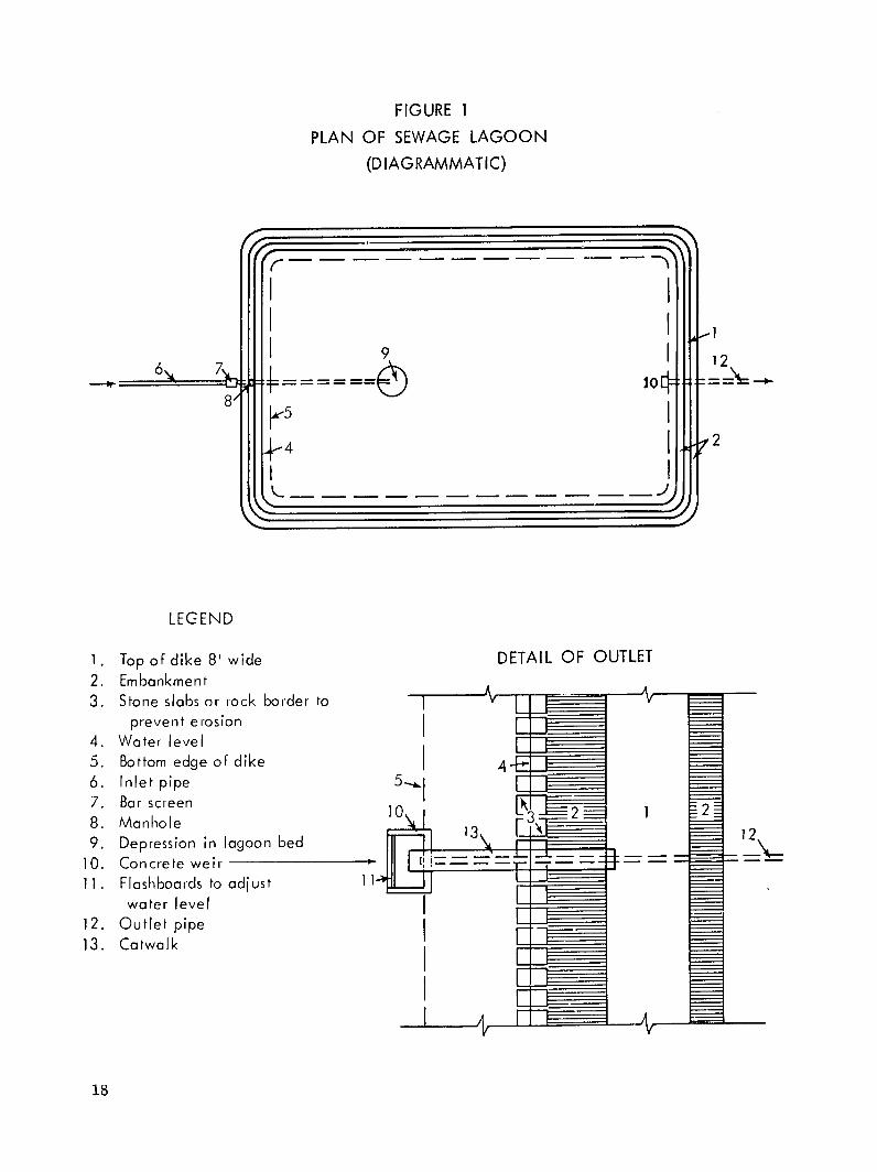
FIGURE 1
PLAN OF SEWAGE LAGOON
(DIAGRAMMATIC)
--------------------- - -- ,,
9 12
S10 8"
4
LEGEND
Top of dike 8' wide DETAIL OF OUTLET Embankment Stone slabs or rock border to
prevent erosion I Water level Bottom edge of dike 4 Inlet pipe Bar screen Manhole Depression in lagoon bed Concrete weir Flashboards to adjust water level
Outlet pipe Catwalk
18
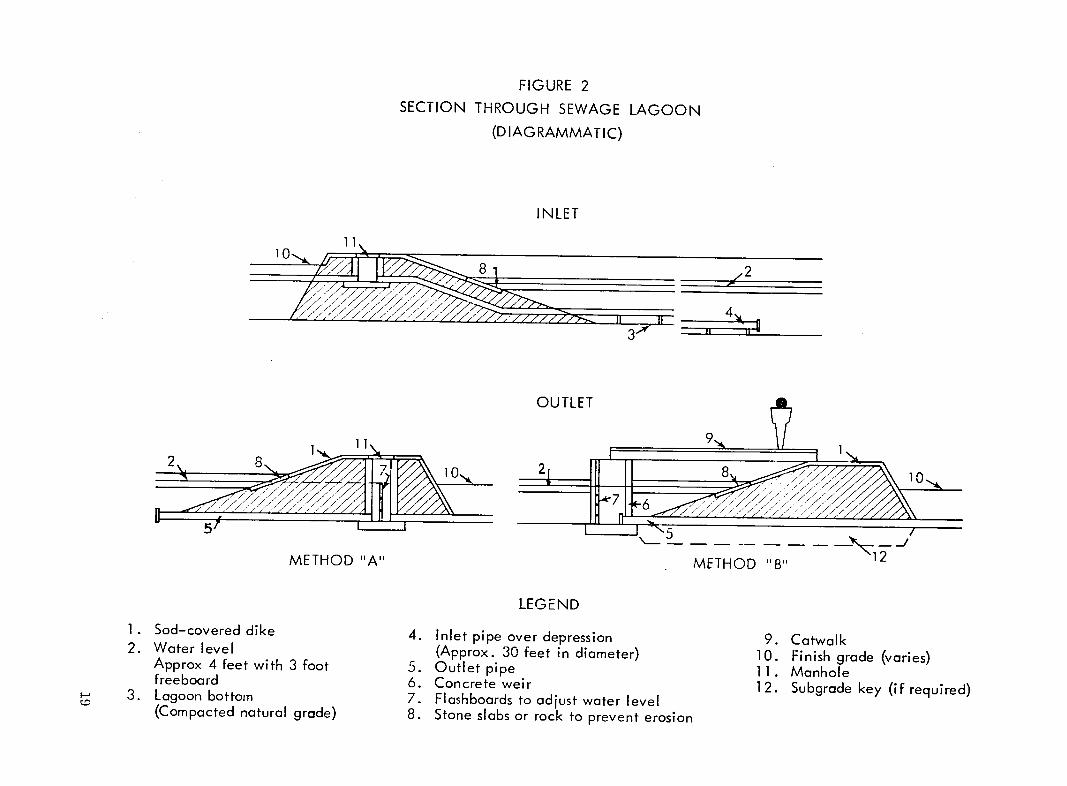
SECTION FIGURE 2
THROUGH SEWAGE
(DIAGRAMMATIC)
LAGOON
11,
/7 7/'
8
INLET
Z2
OUTLET
271
1. 2.
3.
METHOD "A"
Sod-covered dike Water level Approx 4 feet with 3 foot freeboard Lagoon bottom (Compacted natural grade)
METHOD "B"
LEGEND
4. Inlet pipe over depression 9. Catwalk (Approx. 30 feet in diameter) 10. Finish grade (varies)
5. Outlet pipe 11 . Manhole6. Concrete weir 12. Subgrade key (if required)7. Flashboards to adjust water level 8. Stone slabs or rock to prevent erosion
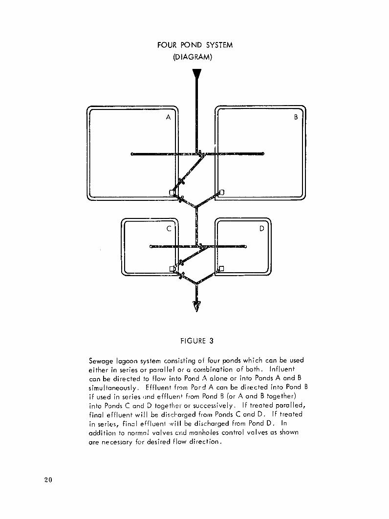
FOUR POND SYSTEM
(DIAGRAM)
A B
c D
FIGURE 3
Sewage lagoon system consisting of four ponds which can be used either in series or parallel or a combination of both. Influent can be directed to flow into Pond A alone or into Ponds A and B simultaneously. Effluent from Pord A can be directed into Pond B if used in series ond effluent from Pond B (or A and B together) into Ponds C and D together or successively. If treated paralled, final effluent will be discharged from Ponds C and D. If treated in series, final efflueni will be discharged from Pond D. In
addition to normal valves cnd manholes control valves as shown are necessary for desired flow direction.
20
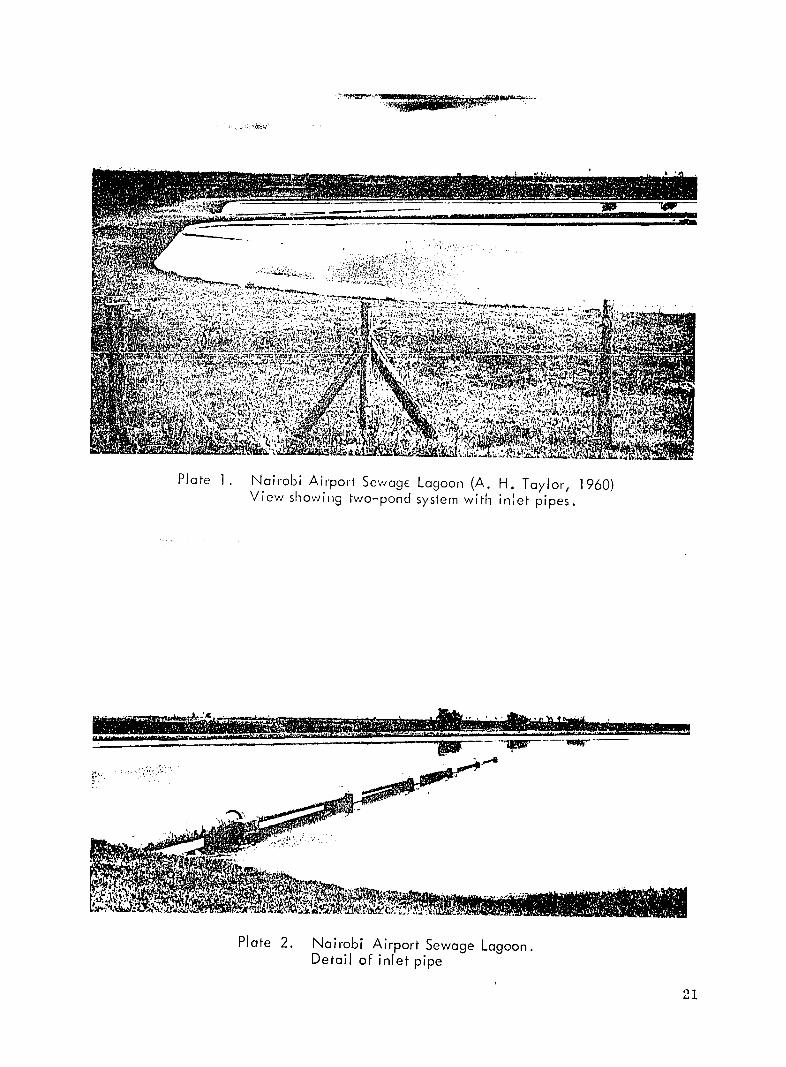
Plate 1 Nairobi Airport Sewage Lagoon (A. H. Taylor, 1960)View showing two-pond system with inlet pipes.
Plate 2. Nairobi Airport Sewage Lagoon.
Detail of inlet pipe
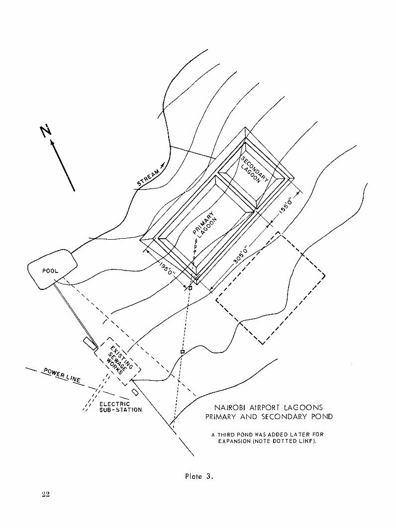
i ELECTRIC ,,SUB-STATrION
. i /FAI'/NAIROBI
PRIMARY
I IPC " AIRPORT LAGOONS.
AND SECONDARY POND
A THIRD POND WAS ADDED LATER FOR EXPANSION (NOTE DOTTED LINF).
,2
Plate 3.
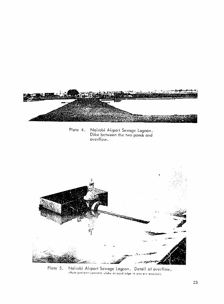
Plate 4. Nairobi Airport Sewage Lagoon.Dike between the two ponds and overflow.
N -
Plate 5. Nairobi Airport Sewage Lagoon. Detail of overflow. fNote precast concrete slabs at pond edge to prevent erosion).
23
244
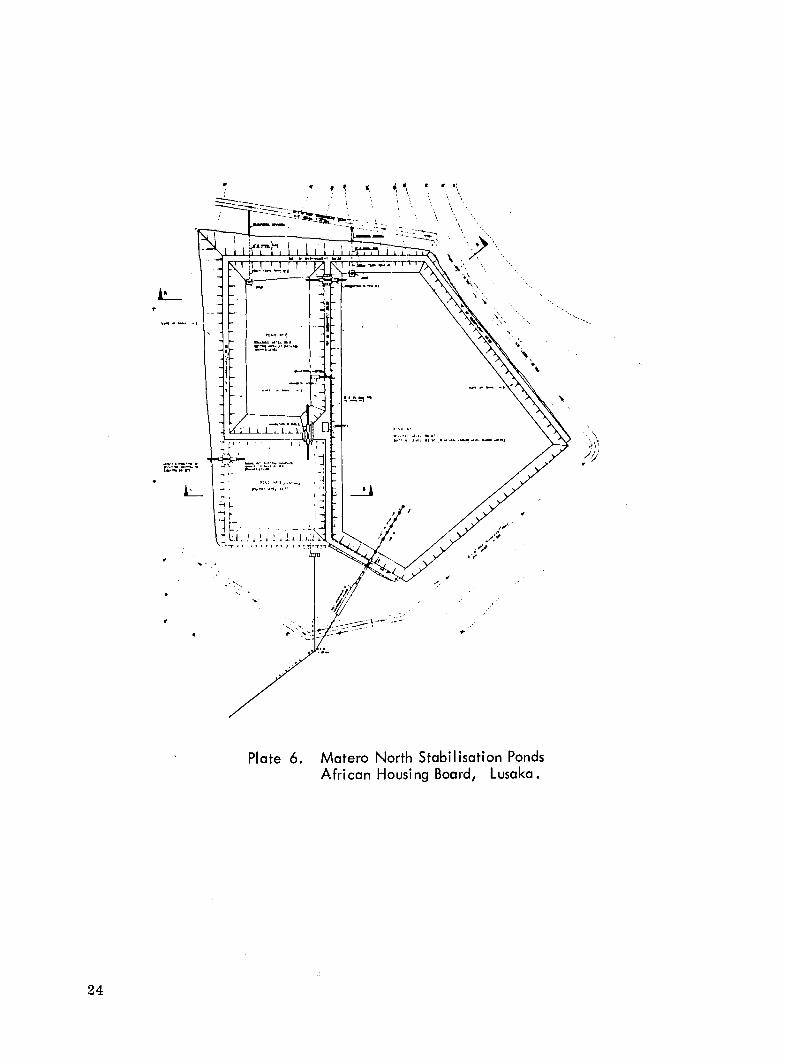
Plate 6. Matero North Stabilisation Ponds African Housing Board, Lusaka.
24
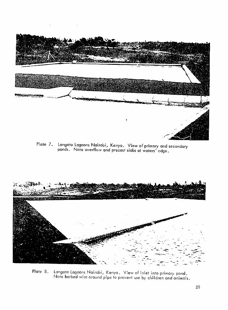
Plate 7. Langata Lagoons Nairobi, Kenya. View of primary and secondaryponds. Note overflow and precast slabs at waters' edge.
Plate 8. Langata Lagoons Nairobi, Kenya. View of inlet into primary pond.
Note barbed wire around pipe to prevent use by children and animals.
25
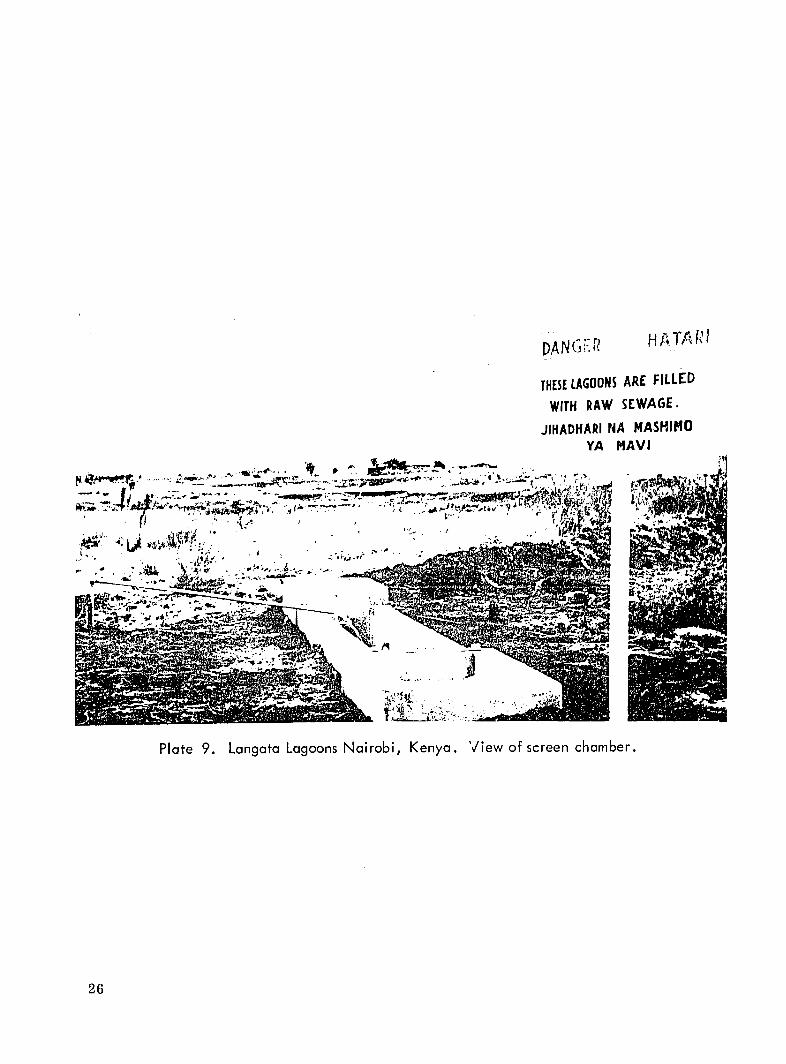
t~- w-V-- -.
DANGJ fTF? THESE LAGOONS ARE FILLED
WITH RAW SEWAGE.
JIHADHIARI NA MASHINO YA MAVI
Iron.:
Plate 9. Langata Lagoons Nairobi, Kenya. View of screen chamber.
26
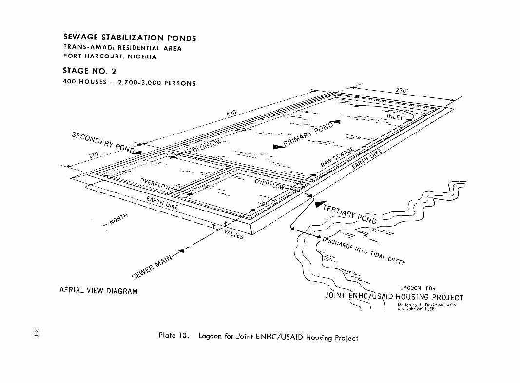
SEWAGE STABILIZATION PONDS TRANS-AMADI RESIDENTIAL AREA PORT HARCOURT, NIGERIA
STAGE NO. 2 400 HOUSES - 2,700-3,000 PERSONS 22G"
IE
K'- _ L AGOO FO
AERAL IEWDIARAMJOINT ENHC/USAID HOUSING PROJECT
,and John MOLLER
Plate 10. Lagoon for Joint ENHC/USAID Housing Project
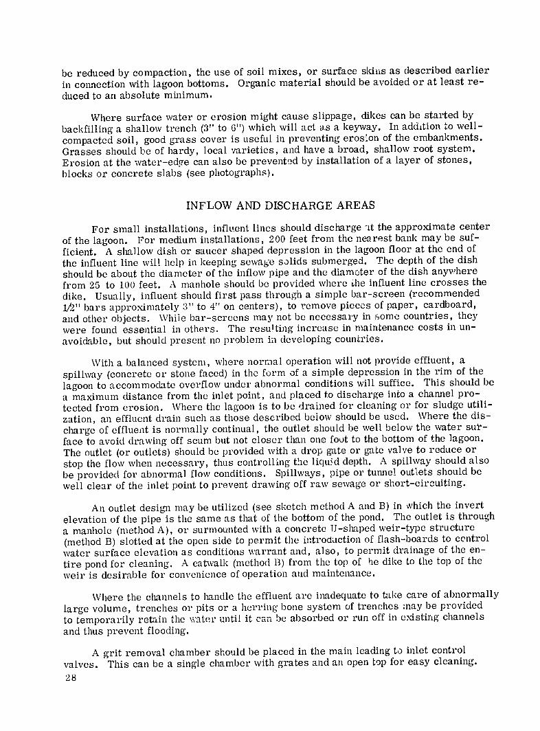
be reduced by compaction, the use of soil mixes, or surface skins as described earlier
in connection with lagoon bottoms. Organic material should be avoided or at least re
duced to an absolute minimum.
Where surface water or erosion might cause slippage, dikes can be started by
backfilling a shallow trench (3" to 6") which will act as a keyway. In addition to wellgood grass cover is useful in preventing erosion of the embankments.compacted soil,
Grasses should be of hardy, local varieties, and have a broad, shallow root system.
Erosion at the water-edge can also be prevented by installation of a layer of stones, blocks or concrete slabs (see photographs).
INFLOW AND DISCHARGE AREAS
For small installations, influent lines should discharge 'Lt the approximate center
of the lagoon. For medium installations, 200 feet from the nearest bank may be suf
ficient. A shallow dish or saucer shaped depression in the lagoon floor at the end of
the influent line will help in keeping sewage solids submerged. The depth of the dish
should be about the diameter of the inflow pipe and the diam.3ter of the dish anywhere
from 25 to 100 feet. A manhole should be provided where he influent line crosses the
dike. Usually, influent should first pass through a simple bar-screen (recommended to 4" on centers), to remove pieces of paper, cardboard,1/2" bars approximately 3"
and other objects. Whiie bar-screens may not be necessary in some countries, they
were found essential in others. The resulting increase in maintenance costs in un
avoidable, but should present no problem in developing countries.
aWith a balanced system, where normal operation will not provide effluent,
spillway (concrete or stone faced) in the form of a simple depression in the rim of the
lagoon to accommodate overflow under abnormal conditions will suffice. This should be a channel proa maximum distance from the inlet point, and placed to discharge into
tected from erosion. Where the lagoon is to be drained for cleaning or for sludge utili
zation, an effluent drain such as those described bejow should be used. Where the dis
charge of effluent is normally continual, the outlet should be well below the water sut
face to avoid drawing off scum but not closer than one foot to the bottom of the lagoon. drop gate or gate valve to reduce orThe outlet (or outlets) should be provided with a
stop the flow when necessary, thus controlling the liquid depth. A spillway should also
be provided for abnormal flow conditions. Spillways, pipe or tunnel outlets should be
well clear of the inlet point to prevent drawing off raw sewage or short-circuiting.
An outlet desigli may be utilized (see sketch method A and B) in which the invert
elevation of the pipe is the same as that of the bottom of the pond. The outlet is through
a manhole (method A), or surmounted with a concrete U-shaped weir-type structure
(method B) slotted at the open side to permit the introduction of flash-boards to control
water surface elevation as conditions warrant and, also, to permit drainage of the en
tire pond for cleaning. A catwalk (method B) from the top of he dike to the top of the
weir is desirable for convenience of operation and maintenance.
Where the channels to handle the effluent are inadequate to take care of abnormally
large volume, trenches or pits or a herring bone system of trenches may be provided
to temporarily retain the water until it can be absorbed or run off in existing channels
and thus prevent flooding.
A grit removal chamber should be placed in the main leading to inlet control a single chamber with grates and an open top for easy cleaning.valves. This can be
28
Two narrow parallel chambers with a diversion gate will allow continued operation while cleaning.
While gravity flow from the collection system is desired for greatest economy,lift stations are sometimes necessary due to non-availability of land in low areas, or in order to keep the lagoon high where surface or near surface-water is a problem.
INITIAL FILLING
Where industrial or commercial wastes are involved, the biochemical treatment process does not start immediately upon filling the lagoon with water and sewage.Natural seeding takes place until the process is established. To allow for dilution and seeding, the lagoon should be partially filled with water before admitting sewage.Similarly, when the lagoon is drained, it may be advisable not to drain it altogether,but retain a fraction of the water for seeding of the next inflow. No seeding is necessary for lagoons handling human wastes only.
After initial filling, a certain length of time (up to 12 weeks) is required for the ponds to settle down. During this time close supervision should be maintained in order to ensure that no fly or mosquito breeding takes place.
ANIMAL LIFE Secondary ponds have successfully supported a number of varieties of fish which
also aid in controlling mosquitoes.
Ducks, geese and water fowl have been known to inhabit the region of lagoons, giving further insect control.
The grazing of domestic animals over the flat areas surrounding the lagoons not only provides food from a (hopefully) lush grass cover, but keeps the height of vegatation to an acceptable level.
PROTECTION
Though the embankments themselves are somewhat of a deterrent to animals and men approaching the lagoon, fences are necessary near built-up areas, especially as a protection to children. Fences 4 to 6 feet in height with an access gate wide enough to allow vehicular access are adequate.
Where valves are in the open they should be locked to prevent tampering. For this reason, as well as protection from the weather, any tools or chemical containers used in connection with the system should be stored in a rain and tamper-proof structure.
MAINTENANCE
A gravity fed lagoon system is simple to service and maintain. Regular periodic checks should be made by someone capable of reading and recording the lagoon depth,extracting samples to check the quality of effluent, and regulating the flow in multiplepond systems. At the same time, inspections should be made of the dikes and the area generally to observe possible leaks, erosion, and (where one exists) to check the grit chamber.
29
At specific intervals, or to meet periodic problems, maintenance should include clearing of surface clogging (scum) caused by wind action, cleaning bar-screens, oiling vlaves, cutting grass on the dikes and surrounding area, and controlling weed growth in the lagoons to prevent breeding of mosquitoes. Bar-screens may have to be cleaned (and waste incinerated) daily. Soundings should be made to determine the general level of sludge accumulation and whether or not excessive accumulation is taking place around the inlet points or in any other area where circulation might be retarded.
For maintenance (such as bottom weed cutting) and detailed inspection, a small float or flat-bottomed boat is extremely useful.
A soil sterilant may be used to control undesirable plant growth and therefore mosquito breeding along the water edge of the dikes, but care should be taken not to destroy desirable grass cover above. Furthermore, the danger exists that leaching of chemicals into the lagoon may cause a film which can retard oxidation. Application of soil sterilants should be made prior to filling of the lagoon. Basic maintenance should not require more than one or two workers.
RODENTS AND INSECTS
Control of mosquitoes and other insects as well as rodents, whose burrows may damage the dikes, should be part of the above mentioned periodic maintenance prc.ram. Poisons, traps and shooting, and the destruction of burrows as they are found keeps the rodents under control. Poisons must be used with care, however, since domestic animals may be killed where the area is grazed, or where fences are not used. If necessary, sprays and dry mixes can be used to combat mosquitoes, though it is rare for them to appear in large numbers in the area of a well-maintained pond. lere again, oils and chemicals which may form a film on the lagoon should be avoided.
SLUDGE ACCUMULATION
As mentioned under Treatment Process, sludge accumulates very slowly. Its actual rate is difficult to predict since it depends on such factors as pond loading in persons per acre, the amount and nature of industrial waste in the system, the extent to which washing machines, or other water-consuming equipment is used, whether or not grit chambers are used, and, in wealthier areas, the use of garbage grinders.
As sludge is a valuable byproduct for agricultural uses, particularly where fertilizer is scarce or expensive, it may well pay, in a multiple system, to shut down one pond at a time to alloW its removal. This may Oe clone after a period of only four or five year's initiallv, and more often thereafter if desired, It might be noted that a fiveyear accumulation may range from only two or three inches to almost two feet, but that for every inch Of depth each acre will yield approximately 3(00 cubic feet of sludge. Subject to adeIuate lagoon desig n, de-sludging of lagoons in tropical areas may not be re(Juired until a fter " to 16; yea's of use.
When removing sludge , care must be taken not to disturb the earth bed or the sludge which has penetrated to seal it. \here commercial skins of any type are used, even greater care must he taken to prevent ])uncture.
3(0
COST
The cost of constructing and operating sewage lagoons is considerably lower thanthose required for building and maintaining conventional sewage disposal systems (50%or less for small plants). Experience in the United States indicates per capita construction costs ranging from S12 to $14, and operating and maintenance costs from $0.20 toS1. 00 annually per population equivalent. African experience shows even lower costs,i.e. per capita construction costs of $5.50 (816. So with sealing of lagoon bottom) and per capita yearly operating costs of 80. 42. Sewage lagoons, compared to conventionaldisposal systems, seem to be especially economical in the case of smaller communitiesof I(),(0 or less population. llowever, in view of the necessity for large tracts of land,they are not considered economical for large cities (Australia being an exception).
NIGHT-SOIL TREATMENT IN LAGOONS
In Africa it was shown that night-soil and conservancy tank contents be disposed of in can"sewage" lagoons. In fact, it was found that a concentration of as high as2, 000 people per acre of lagoon would still maintain aerobic conditions. This indicates
that lagoons can also be uscd for disposal of human waste in the absence of an existing sewer system, j)provided enough water is available to allow the creation of conditionsnecessary for the oxidation process. Location, design, loading conditions, etc. , forsuch lagoons, howe\'er, should not be determined without the assistance of properlyqualified teclmical personnel.
COMMUNITY RELATIONS AND THE LAW
Frecluently, when planning sewage lagoons, the feelings of the community are ignored, or not sought, possibly resulting in unnecessary opposition to the system generally. As soon as it is known tlat a sewage system is planned, and it is determined thatlagoons are a practical solution, the public should be informed of both the nature of rheproject and its advantages. The economy factor will appeal to many who might opposea new sewage system generally in that lagoons result in substantial cost reductions ascompared with the more sophisticated treatment l)lants-generally in the order of 50percent or more. Cost, however, is not as important to many as physiological factors involving l)OSSiblc nuisances.
If the lagoon is )roperly located, designed and built, fears of odors, water pollution , unsightly floating materials, rodents and insects are largely unfounded. Meetingswith iltcrestcd l)ublic bOdlies and the use of local co munications media should be a partof what amounts to an educational progTam to inform, interest, and allay the possibleobjections of the general l)lblic. )ointing out advantages of the system with successfulexatml)lCs in other com munities is a useful technique. Community leaders might well betaken on tours of nearby lagoon systems, while larger tours open to anyone, should beorganized once the local lagoon is in operation. In this, as with other matters, fear isgenerated by the unknown, while understanding will usua!ly result in cooperation, or at least accel)tance.
Like public opinion, the law plays a dccisivc but more immediate role in not onlywhere a sewage treatment plant will be built, but whether it will be built at all. Under"Site Location" it was noted that zoning ordinances determine the general area for elements such as sewage disposal systems. E'ven where zoning laws and health ordinances
31
condone lagoons, however, concern for the maintenance of property values can become a serious consideration, and may, depending upon the case, result in court action.
Indemnification may be necessary as a result of constructing lagoons in residential areas. Compensation is required for full or partial land takings, as well as for any income loss or nuisances tlat may occur clue to faulty lagoons. Payment for complete parcels of land is normally based on the appraised fair market value. In purchasing partial plots, however, greater compensation may be necessary clue to possible reduced income or reduced resale value of the remaining portion.
Four points must be kept in mind concerning possible claims by adjoining property owners and in connection \Vith the purchase of partial parcels of land:
(1) Vlat accident hazards may result? Injury to children or livestock pose problems but can be overcome by the use of adecjuate fencing and maintenance.
(2) \Valt health hazards are involved? Pollution of ground water and domestic water sources by seepage from the lagoon may usually be overcome through careful dcsigl, construction and maintenance.
(3) What nuisances may arise? Unsightly solids, odors and mosquitoes can also be discounted where properly located, desigied and maintained lagoons are concerned. \Where icing conditions exist, periods of offensive odor in the immediate area may result when the ice breaks up.
(4) What is the effect of sewage lagoons on the production and resale value of the adjoining parcels of land ? Farm operations are naturally affected by any reduction in land area, but no more so by lagoons than from any other use to which the land may be put. Since lagoon construction may affect the possible use-range or resale value of plots in the adjoining area, it is often more economical to buy whole parcels at market value thWnn to pay compensation for possible future loss of income fl'om partial plots. Even when not immediately needed, the excess land is a good investment for the community, and may well be needed for expansion of the system as the area develops.
32
SELECTED BIBLIOGRAPIIY
1. Jewell R. Benson, "How to Prevent Sevage Lagoon Seepage", Ridgewood, N.J. Public Works Journal Corp., Public Works, Vol. 93, No. 3, March 1962.
2. "Design Criteria for Seepage Pits", FHA Completed Studies and Reports Number 22, 1964.
3. Donald L. Floan, "Installing a Sewage Lagoon and Lift Station", Chicago Company,Water and Sewage Work, Vol. 18, No. 8, May 1961.
4. Housing and Home Finance Agency, Federal Housing Administration, "MinimumDesign Standards for Community Sewerage Systems", FHA No. 720, Washington, July 1963.
5. 0. L. Meyer, "Aeration System", Ridgewood, N. J., Public Works Journal Corp.Public Works, Vol. 93, No. 8, August 1962.
6. Donald A. Mills, "Depth and Loading Rates of Oxidation Ponds", Chicago,Scranton Publishing Company, Water and Sewage Works, Vol. 108, No. 8, 1961.
7. George F. Papenfuss and Mary B. Allen, "General Features of Algae Growth In Sewage Oxidation Ponds", Sacramento, State Water Pollution Control Board Publication, Number 13, 1955.
3. William S. Ratchford, "Sewage Lagoons", Hallowell, Maine, Maine MunicipalAssociation, "The Maine Townsman", Vol. XXIII, No. 6, June 1961.
9. Don Romero, "Nature's Way with Waste", New York 21, National Civic Review,National Municipal League, Vol. XLIX, 1960.
10. Shaw, Meiring, and Van Eck, "Preliminary Results of Research on Raw SewageStabilization Ponds", Council for Scientific and Industrial Research, CSIR SpecialReport No. 189, Pretoria, South Africa, 1962.
11. Ernest W. Steel, "Water Supply and Sewerage", New York, McGraw-Hill Book Company, Inc. 1953.
12. Paul G. W. Walker, "Rotor Aeration of Oxidation Ditches", Chicago, Scranton Publishing Co., Water and Sewage Works, Vol. 109, No. 6, June 1962.
13. William J. Wenzel, "Low Cost Treatment and Disposal Method", New York Engineering News-Record, August 20, 1953.
14. P.T.A. Zeller and F.E. Giesecke, "Secondary Treatment of Sewage in an Artificial Lake", New York Engineering News-Record, Nov. 1963.
33
15. Ted L. Townsend, "Sewage Lagoons ",Appraisal Institute of Canada, Appraisal Institute Magazine, December 1963.
16. D. H. Ccldwell, "Sewage Oxidation Ponds, Performance, Operation and Design", Sewage Works Journai 18, 1946.
17. Smal Ihorst, Wal ton and Meyers, "Design .and Operation of Oxidation Ponds", Public Works, 84, 1953.
18. Towne, Bartsch and Davis, "Raw Sewage Stabilization Ponds in the Dakotas", Sewage and Industrial Wastes, 29, 1957.
19. Ingram, Towne and Horning, "Selected References on Waste Stabilization Ponds", Proceedings on Symposium on Waste Stabilization Laoons, U.S. PHS, Region VI, Kansas City, Mo., 1960.
20. Bureau Central d'Etudes Pour les Equipments d'Outre-Mer, Service de I'Habitat et Urbanisme, "Etangs et Bassins d'Dpuration d'Eajx Usees en Region Tropicale", Bulletins d'Information No. 25, 1963.
21. W. W. Towne, and W. H. Davis, "Sewage Treatment by Raw Sewage Stabilization Ponds", Journal of the Sanitary Engineering Division, ASCE, Paper 1337, August 1957.
22. Van Heuelen, Smith, and Hopkins, "Waste Stabilization Lagoons", Design Construction and Operating PracHices among M;ssouri Basin States", a Committee Report approved by the Missouri Basin Engineering Health Council, Jan. 21, 1960.
23. Neel, McDermott and Monday, "Experimental Lagooning of Raw Sewage at Fayette, Missouri", Journal Water Pollution Control Federation, June 1961.
24. Ralph Porges, "Waste Stabilization Ponds, Facts and Figures", U. S. Department of Health, Education and Welfare, Robert A. Taft Sanitary Engineering Center, Cincinatti, Ohio.
25. A. H. Taylor, "Sewage Lagoons for Low-Cost Disposal", East Africa Medical Journal, Vol. 37, No. 10, October 1960.
26. E. R. Hermann and E. F. Gloyna, "The Design of Oxidation Ponds", Sanitary Engineering Research Lab., Dept. of Civil Engineering, University of Texas, 1955.
27. A. F. Bartsch, "Biolonical and Chemical Aspects of Organic Waste Lagoons", U. S. Dept. of Health, Education and Welfare, PHS, Robert A. Taft Sanitary Engineering Center, Cincinatti, Ohio.
28. Marais and Shaw, "A Rational Theory for the Design of Sewage Stabilization Ponds in Central and Southern Africa"., Trans. S. Afr. Inst. Civ. Engineers, Vol. 3, No. 11, Nov. 1961.
29. H. Lister, "Treatment of Sewage with Special Reference to the Use of Stabilization Ponds", Housing Advisory Council, Hatfield Road, Salisbury, Rhodesia.
34
30. Marais, Shaw, and Asce, "A Rational Theory for the Design of Sewage StabilizationPonds in Central and South Africa", The Civil Engineer in S. Africa, Vol. 3, No. 11, November 1961.
31. Marais, "A Design Chart for a Series of Oxidation Ponds Treating Raw Sewage", The Civil Engineer in S. Africa, Vol. 5, No. 9, September 1963.
32. Marais, "A Rational Theory for the Design of Sewage Stabilization Ponds in Tropical and Subtropical Areas", CCTA/WHO Symposium on Hygiene and Sanitation in Relation to Housing, CCTA Publ. No. 84, Niamey 1961.
33. Fair and Geyer, "Water Supply and Waste Water Disposal", John Wiley and Sons,New York, 1957.
34. Meenaghan and Alley, "Evaluation of Waste Stabilization Pond Performance",Tex. Wat. Pollut. Contr. Assoc., 1963.
35. Hodgson, "Stabilization Ponds for a Small African Urban Area", J. Wat. Pollut,Contr. Fed., Jan. 1964.
36. Neel, McDermott, and Monday, "Experimental Lagooning of Raw Sewage at Fayette, Mo. ", J. Wat. Pollut. Contr., 1961.
37. Silva, and Papenfuss, "A Systematic Study of the Algae of Sewage Oxidation Ponds',Publ. No. 7, Calif. State Wtr. Pollut. Board, 1953
38. J.L.A. Watson, "Oxidation Ponds and Use of Effluent in Israel", Proc. Instn. of Civ. Engrs., 1962.
39. Parker, Jones, and Taylor, "Purification of Sewage inLagoons", Sew. and Ind.Wastes, 1950.
40. Vincent, Algie, and Marais, "A System of Sanitation for Low-Cost High-DensityHousing", Niamey, CCTA Publ. No. 84, 1961.
41. V. A. Shaw, "A System for the Disposal of Night-Soil and Conservancy Tank Contents in Stabilization Ponds", Public Health, No. 63, 2, 1963.
42. Var Eck, "Theory of Stabilization Ponds and its Implication on Their Design andOperation", CCTA/WHO Specialist Conference, Pretoria, 1960.
43. Williamson, Arthur E., "Summary Report on Stabilization Ponds and AeratedLagoons", prepared for Missouri Basin Engineering Health Council, 1964.
35